EP1878362B1 - Verstellbarer Liegerahmen - Google Patents
Verstellbarer Liegerahmen Download PDFInfo
- Publication number
- EP1878362B1 EP1878362B1 EP07107627A EP07107627A EP1878362B1 EP 1878362 B1 EP1878362 B1 EP 1878362B1 EP 07107627 A EP07107627 A EP 07107627A EP 07107627 A EP07107627 A EP 07107627A EP 1878362 B1 EP1878362 B1 EP 1878362B1
- Authority
- EP
- European Patent Office
- Prior art keywords
- neck support
- back part
- slot
- bed frame
- bolt
- Prior art date
- Legal status (The legal status is an assumption and is not a legal conclusion. Google has not performed a legal analysis and makes no representation as to the accuracy of the status listed.)
- Not-in-force
Links
- 229920003023 plastic Polymers 0.000 claims description 4
- 239000004033 plastic Substances 0.000 claims description 4
- 239000000463 material Substances 0.000 claims 2
- 239000002184 metal Substances 0.000 claims 1
- 238000006073 displacement reaction Methods 0.000 description 4
- 238000010276 construction Methods 0.000 description 3
- 230000006835 compression Effects 0.000 description 2
- 238000007906 compression Methods 0.000 description 2
- FGRBYDKOBBBPOI-UHFFFAOYSA-N 10,10-dioxo-2-[4-(N-phenylanilino)phenyl]thioxanthen-9-one Chemical compound O=C1c2ccccc2S(=O)(=O)c2ccc(cc12)-c1ccc(cc1)N(c1ccccc1)c1ccccc1 FGRBYDKOBBBPOI-UHFFFAOYSA-N 0.000 description 1
- 230000008878 coupling Effects 0.000 description 1
- 238000010168 coupling process Methods 0.000 description 1
- 238000005859 coupling reaction Methods 0.000 description 1
- 230000000694 effects Effects 0.000 description 1
- 238000009434 installation Methods 0.000 description 1
- 230000000284 resting effect Effects 0.000 description 1
Images




Classifications
-
- A—HUMAN NECESSITIES
- A47—FURNITURE; DOMESTIC ARTICLES OR APPLIANCES; COFFEE MILLS; SPICE MILLS; SUCTION CLEANERS IN GENERAL
- A47C—CHAIRS; SOFAS; BEDS
- A47C20/00—Head-, foot- or like rests for beds, sofas or the like
- A47C20/08—Head-, foot- or like rests for beds, sofas or the like with means for adjusting two or more rests simultaneously
-
- A—HUMAN NECESSITIES
- A47—FURNITURE; DOMESTIC ARTICLES OR APPLIANCES; COFFEE MILLS; SPICE MILLS; SUCTION CLEANERS IN GENERAL
- A47C—CHAIRS; SOFAS; BEDS
- A47C20/00—Head-, foot- or like rests for beds, sofas or the like
- A47C20/04—Head-, foot- or like rests for beds, sofas or the like with adjustable inclination
- A47C20/041—Head-, foot- or like rests for beds, sofas or the like with adjustable inclination by electric motors
Definitions
- the present invention relates to an adjustable reclining frame with a base frame, a pivotally connected to the side rails of the base frame back part and a neck support, wherein the back part and the neck support lie in a basic position in a common plane with the base frame and are swinging out of this basic position, wherein the neck support towards the back part leading up and movable in the direction of the head end of the base frame and on its longitudinal sides in guide plates from the basic position out by a certain angle relative to the back are swinging leading and the neck support after reaching the maximum Voreil too with simultaneous pivoting of the back part in the direction the head end of the base frame is displaceable.
- a lying frame of the generic type is from the DE 296 20 699 U1 known.
- the present invention has for its object to make an adjustable reclining frame of the generic type so that the movements especially the neck support, namely its advance relative to the back and its movement in the direction of the head end of the base frame with comparatively simple and inexpensive to produce fittings is possible.
- the neck support is slidably guided in slots of the guide plates, and the guide plates are each pivotally connected to a fitting attached to the back part about a bearing pin and that the guide plates have a concentric with this extending slot at a distance from the bearing pin through which passes through a guide bolt attached to the fitting, wherein the size of the slots determines the maximum angle of the leading edge of the neck support.
- the neck support is carried out in the lying frame according to the invention by a displacement in designated oblong holes of a guide tab, the entire fitting construction for coupling of back and neck support can be relatively simple and comes with a few inexpensive producible items from.
- the guide plates are pivotally connected to a fitting attached to the back part about a bearing pin and that the guide tabs at a distance from the bearing pin have a concentric extending to this slot through which passes a fastened to the fitting guide pin , wherein the size of the elongated hole determines the maximum angle of the leading edge of the neck support.
- FIG. 1 is the head portion of a generally designated by the reference numeral 1 adjustable reclining frame shown comprising a base frame 2, a pivotally connected thereto back part 3 and a neck support 4, which in turn is pivotally connected to the back part 3.
- the neck support 4 is movable in the direction of the head end 2a of the base frame.
- the basic structure of the swivel fittings 5 on the two longitudinal sides of the neck support 4 is equal to each other, except that in each case a left and a right-side design is required.
- the pivot fitting 5 is connected to a fitting 6 fixed to the back part 3.
- the back part 3 is pivotally connected to the base frame 2 about a pivot point 7.
- the neck support 4 is slidably guided in a slot 8 of a guide plate 9, wherein the guide plate 9 is pivotally connected about a bearing pin 10 with the fixed part 3 connected to the fitting part 6. At a distance from the bearing pin 10, the guide plate 9 is provided with a concentric with the bearing pin 10 extending slot 11 which is penetrated by a guide pin 12 which is fixed to the fitting part 6.
- a further pivoting movement of the neck support 4 has from the position described above with the result that the back part 3 is pivoted upwards from its basic position, since now the angle between the neck support 4 and the back part 3 remains unchanged.
- FIGS. 1 to 3 make it clear that the guide pin 12 is located in the home position located back part 3 and neck support 4 at one end of the slot 11 and at the beginning pivoted neck support 4 at the other end of the slot 11 and is supported there.
- a set-up lever 13 This raising lever 13 is pivotally mounted in its central region about a pivot point 14 on a support bracket 15.
- the raising lever 13 is pivotally connected in one of its end regions with a drive lever 16, which is preferably driven by a motor.
- the leadership of the neck support 4 is stabilized within the elongated hole 8, located on the neck support 4 at a distance from the bolt 17 to which the raising lever 13 engages, another, slidable within the slot 8 and connected to the neck support 4 bolts 17 a.
- the already mentioned support tab 15 is pivotally connected to the fitting 6 mounted on the guide pin 12 with the fitting 6.
- FIG. 2 is as well as in Figure 7a
- the pivot fitting is shown in the backrest 3 and headrest 4 located in the basic position, ie, the said parts lie in one plane with the base frame 2. It becomes clear that the guide pin 12 within the arcuate slot 11 in this position in which the head end 2a of Base frame facing end portion of the arcuate slot 11 is located.
- the now occupied angular position between the back part 3 and neck support 4 can not be changed by further pivoting, so that a further rotation of the raising lever 13 in the clockwise direction has the consequence that the back part 3 is pivoted together with the neck support 4 upwards.
- the neck support 4 is displaced in the direction of the head end 2a of the base frame 2, which is possible by guiding the neck support 4 within the elongated hole 8 of the guide tongue 9.
- FIGS. 4 and 7c here show intermediate positions in which the back part 3 is pivoted upward in an intermediate position out of its basic position and in which the neck support 4 is likewise displaced outwards into an intermediate position within the oblong hole 4.
- the fitting part 6 respectively represents the position of the back part 3, since this fitting part 6 is known to be firmly connected to the back part 3.
- the neck support 4 can be pivoted not only relative to the back part 3 leading, but also a shift of the neck support 4 in the direction of the head end 2a of the base frame 2 is possible , This displacement of the neck support avoids compression of an overlying mattress or other support.
- the neck support 4 is fixedly connected to an angle section 18, which in turn is held and guided by the bolts 17 and 17a in the slot 8 of the guide plate 9.
- an advantageously consisting of two halves 19a and 19b slide plastic is provided, which is also from the bolts 17 and 17a pass and which rests on the two outer surfaces of the guide plate 9, so that a good lubricity of the neck support 4 relative to the guide tab 9 results.
- the reference numeral 19b half of the carriage is provided with a projection 19c, which projects into the slot 8, whereby a further improvement of the leadership of the angle profile 18 and thus the neck support 4 is achieved.
- the slot 8 is rectilinear, so that the angular position of the neck support 4 is not changed relative to the back part 3 by the displacement of the neck support 4.
- FIG. 9 an embodiment of the invention is shown in which the slot 8 of the guide plate 9 is bent, so that in addition to a displacement of the neck support 4 in the direction of the head end of the base frame 2, a change in the angular position of the neck support 4 relative to the back part 3 is possible without that the guide plate 9 can or must change its angular position relative to the back part 3.
- the representation after FIG. 9 shows a convex to the underside of the pivot fitting 5 toward the slot 8, with the result that the neck support 4 with increasing pivoting of the entire pivot fitting 5 can assume an increasingly steeper position. It is easily understood by a person skilled in the art that certain and possibly desired effects for the installation position of the neck support 4 can be achieved by other curvature arrangements, possibly also in combination with rectilinear sections of the respective elongated hole 8.
Landscapes
- Health & Medical Sciences (AREA)
- General Health & Medical Sciences (AREA)
- Nursing (AREA)
- Chairs For Special Purposes, Such As Reclining Chairs (AREA)
- Invalid Beds And Related Equipment (AREA)
- Body Structure For Vehicles (AREA)
- Chair Legs, Seat Parts, And Backrests (AREA)
- Soil Working Implements (AREA)
Description
- Die vorliegende Erfindung betrifft einen verstellbaren Liegerahmen mit einem Grundrahmen, einem an den Seitenholmen des Grundrahmens schwenkbar angeschlossenen Rückenteil und einer Nackenstütze, wobei das Rückenteil und die Nackenstütze in einer Grundstellung in einer gemeinsamen Ebene mit dem Grundrahmen liegen und aus dieser Grundstellung heraus hochschwenkbar sind, wobei die Nackenstütze gegenüber dem Rückenteil voreilend hochschwenkbar und in Richtung des Kopfendes des Grundrahmens bewegbar und an ihren Längsseiten in Führungslaschen aus der Grundstellung heraus um einen bestimmten Winkelbetrag gegenüber dem Rückenteil voreilend ausschwenkbar sind und die Nackenstütze nach Erreichen der maximalen Voreilstellung bei gleichzeitigem Verschwenken des Rückenteiles in Richtung des Kopfendes des Grundrahmens verschiebbar ist.
- Ein Liegerahmen der gattungsgemäßen Art ist aus der
DE 296 20 699 U1 bekannt. - Bei der vorbekannten Konstruktion wird die Voreilung der Nackenstütze gegenüber dem Rückenteil und die Bewegung der Nackenstütze in Richtung des Kopfendes des Grundrahmens, durch welche eine Stauchung einer auf dem Liegerahmen aufliegenden Matratze oder dergleichen weitestgehend vermieden wird, erreicht durch Schwenkbeschläge in Form von Gelenkketten.
- Der vorliegenden Erfindung liegt die Aufgabe zugrunde, einen verstellbaren Liegerahmen der gattungsgemäßen Art so zu gestalten, dass die Bewegungsabläufe insbesondere der Nackenstütze, nämlich deren Voreilung gegenüber dem Rückenteil und deren Bewegung in Richtung des Kopfendes des Grundrahmens mit vergleichsweise einfachen und kostengünstig herstellbaren Beschlägen möglich ist.
- Diese Aufgabe wird erfindungsgemäß dadurch gelöst, dass die Nackenstütze in Langlöchern der Führungslaschen verschiebbar geführt ist, und die Führungslaschen jeweils mit einem am Rückenteil befestigten Beschlagteil um einen Lagerbolzen schwenkbar verbunden sind und dass die Führungslaschen in einem Abstand zum Lagerbolzen ein konzentrisch zu diesem verlaufendes Langloch aufweisen, durch den ein an dem Beschlagteil befestigter Führungsbolzen hindurchtritt, wobei durch die Größe der Langlöcher der maximale Winkel der Voreilung der Nackenstütze bestimmt ist.
- Bedingt durch die Tatsache, dass die Nackenstütze beim erfindungsgemäßen Liegerahmen durch eine Verschiebung in dafür vorgesehenen Langlöchern einer Führungslasche erfolgt, kann die gesamte Beschlagkonstruktion zur Kopplung von Rückenteil und Nackenstütze relativ einfach gestaltet sein und kommt mit wenigen, preiswert herstellbaren Einzelteilen aus.
- Nach einer Weiterentwicklung der Erfindung ist vorgesehen, dass die Führungslaschen jeweils mit einem am Rückenteil befestigten Beschlagteil um einen Lagerbolzen schwenkbar verbunden sind und dass die Führungslaschen in einem Abstand zum Lagerbolzen ein konzentrisch zu diesem verlaufendes Langloch aufweisen, durch den ein an dem Beschlagteil befestigter Führungsbolzen hindurchtritt, wobei durch die Größe des Langloches der maximale Winkel der Voreilung der Nackenstütze bestimmt ist.
- Weitere Merkmale der Erfindung sind Gegenstand weiterer Unteransprüche.
- In den beigefügten Zeichnungen sind Ausführmgsbeispiele der Erfindung dargestellt, die im Folgenden näher beschrieben werden.
- Es zeigen:
- Figur 1
- eine schematisch dargestellte Seitenansicht eines Liegerahmens mit teilweise hochgeschwenktem Rückenteil und daran angelenkter Nackenstütze
- Figur 2
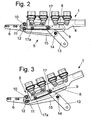
- eine der
Figur 1 entsprechende Seitenansicht der relevanten Beschlagteile zur Bewegung von Rückenteil und Nackenstütze in Grundstellung - Figur 3
- eine der
Figur 2 entsprechende Seitenansicht mit zunächst nur hochgeschwenkter Nackenstütze - Figur 4
- eine den
Figuren 2 und 3 entsprechende Darstellung einer weiteren Hochschwenkposition, bei der auch das Rückenteil aus einer Grundstellung heraus teilweise verschwenkt ist - Figur 5
- eine den
Figuren 2 bis 4 entsprechende Seitenansicht bei völlig hochgeschwenktem Rückenteil - Figur 6
- eine perspektivische Sprengbilddarstellung eines Schwenkbeschlages zur Steuerung der Bewegungen des Rückenteiles und der Nackenstütze
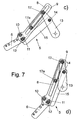
- Figuren 7 a bis 7 d
- den
Figuren 2 bis 5 entsprechende Seitenansichten lediglich des Schwenkbeschlages zur Steuerung der Bewegungen von Rückenteil und Nackenstütze - Figur 8
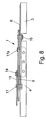
- eine Ansicht in Richtung des Pfeiles VIII in
Figur 7a - Figur 9
- eine der
Figur 7b entsprechende Seitenansicht eines Schwenkbeschlages für einen verstellbaren Liegerahmen nach einem weiteren Ausführungsbeispiel der Erfindung. - In
Figur 1 ist der Kopfbereich eines insgesamt mit dem Bezugszeichen 1 bezeichneten verstellbaren Liegerahmens dargestellt, der einen Grundrahmen 2, ein daran schwenkbar angeschlossenes Rückenteil 3 sowie eine Nackenstütze 4 umfasst, die ihrerseits schwenkbar am Rückenteil 3 angeschlossen ist. Darüber hinaus ist die Nackenstütze 4 in Richtung des Kopfendes 2a des Grundrahmens beweglich. - Die Verbindung zwischen der Nackenstütze 4 und dem Rückenteil 3 erfolgt über Schwenkbeschläge 5, die jeweils im Bereich der Längsseiten der Nackenstütze 4 vorgesehen sind und von denen einer in den Zeichnungen dargestellt ist. Der grundsätzliche Aufbau der Schwenkbeschläge 5 an den beiden Längsseiten der Nackenstütze 4 ist untereinander gleich, abgesehen davon, dass jeweils eine links- und eine rechtsseitige Ausführung erforderlich ist.
- Im Folgenden wird der Aufbau und die Wirkungsweise unter Bezugnahme auf einen derartigen Schwenkbeschlag 5 beschrieben.
- Wie die Zeichnungen zeigen, ist der Schwenkbeschlag 5 mit einem Beschlagteil 6 fest mit dem Rückenteil 3 verbunden. Das Rückenteil 3 ist um einen Drehpunkt 7 schwenkbar am Grundrahmen 2 angeschlossen.
- Die Nackenstütze 4 ist verschiebbar in einem Langloch 8 einer Führungslasche 9 geführt, wobei die Führungslasche 9 um einen Lagerbolzen 10 verschwenkbar mit dem fest an dem Rückenteil 3 angeschlossenen Beschlagteil 6 verbunden ist. In einem Abstand zum Lagerbolzen 10 ist die Führungslasche 9 mit einem konzentrisch zum Lagerbolzen 10 verlaufenden Langloch 11 ausgestattet, welches von einem Führungsbolzen 12 durchtreten ist, der am Beschlagteil 6 befestigt ist.
- Durch dieses Langloch 11 und den in dieses Langloch 11 eingreifenden Führungsbolzen 12 wird die Möglichkeit geschaffen, die Nackenstütze 4 aus einer Grundstellung heraus, in der sich Rückenteil 3 und Nackenstütze 4 in einer gemeinsamen Ebene mit dem Grundrahmen 2 befinden und wie es in
Figur 2 dargestellt ist, zunächst einmal um einen bestimmten Winkelbetrag voreilend gegenüber dem Rückenteil 3 nach oben zu schwenken, wobei das Rückenteil 3 zunächst noch in seiner Grundstellung in einer Ebene mit dem Grundrahmen 2 verbleibt. Diese Position ist inFigur 3 dargestellt. - Eine weitere Aufschwenkbewegung der Nackenstütze 4 hat ab der vorstehend beschriebenen Position zur Folge, dass sich auch das Rückenteil 3 aus seiner Grundstellung heraus nach oben verschwenkt, da nun der Winkel zwischen der Nackenstütze 4 und dem Rückenteil 3 unverändert bleibt.
- Die
Figuren 1 bis 3 machen deutlich, dass sich der Führungsbolzen 12 bei in Grundstellung befindlichem Rückenteil 3 und Nackenstütze 4 an einem Ende des Langloches 11 und bei voreilend aufgeschwenkter Nackenstütze 4 am anderen Ende des Langloches 11 befindet und dort abstützt. - Die Kräfte zum Aufstellen oder Aufschwenken der Nackenstütze 4 und des Rückenteiles 3 werden auf den Schwenkbeschlag 5 übertragen durch einen Aufstellhebel 13. Dieser Aufstellhebel 13 ist in seinem mittleren Bereich um einen Drehpunkt 14 an einer Stützlasche 15 schwenkbar gelagert. Darüber hinaus ist der Aufstellhebel 13 in einem seiner Endbereiche mit einem Antriebshebel 16 schwenkbar verbunden, der vorzugsweise motorisch antreibbar ist.
- An seinem gegenüberliegenden Ende ist der Aufstellhebel 13 mit einem mit der Nackenstütze 4 verbundenen Bolzen 17 gelenkig verbunden, wobei dieser Bolzen 17 innerhalb des Langloches 8 der Führungslasche 9 verschiebbar ist.
- Damit die Führung der Nackenstütze 4 innerhalb des Langloches 8 stabilisiert ist, befindet sich an der Nackenstütze 4 in einem Abstand zum Bolzen 17, an dem der Aufstellhebel 13 angreift, ein weiterer, innerhalb des Langloches 8 verschiebbarer und mit der Nackenstütze 4 verbundener Bolzen 17a.
- Die schon erwähnte Stützlasche 15 ist um den am Beschlagteil 6 befestigten Führungsbolzen 12 verschwenkbar mit dem Beschlagteil 6 verbunden.
- Nachdem nun alle Bestandteile des Schwenkbeschlages 5 beschrieben sind, kann unter Bezugnahme auf die
Figuren 2 bis 5 sowie 7a bis 7d der Funktionsablauf eines derartigen Schwenkbeschlages 5 beschrieben werden. - In der
Figur 2 ist ebenso wie inFigur 7a der Schwenkbeschlag bei in Grundstellung befindlichem Rückenteil 3 und Nackenstütze 4 gezeigt, d.h., die besagten Teile liegen in einer Ebene mit dem Grundrahmen 2. Es wird dabei deutlich, dass der Führungsbolzen 12 innerhalb des bogenförmigen Langloches 11 in dieser Position in dem dem Kopfende 2a des Grundrahmens zugewandten Endbereich des bogenförmigen Langloches 11 liegt. - Wird nun aus dieser Grundstellung heraus der Aufstellhebel 13 durch den vorzugsweise motorbetriebenen Antriebshebel 16 im Uhrzeigersinne um den Lagerbolzen 14 verschwenkt, wird zunächst nur die Nackenstütze 4 gegenüber dem mit dem Rückenteil fest verbundenen Beschlagteil 6 um den Lagerbolzen 10 verschwenkt. Dabei gleitet die Führungslasche 9 im Bereich ihres bogenförmigen Langloches 11 über den Führungsbolzen 12 hinweg, bis dieser an dem dem Rückenteil 3 und somit auch dem damit verbundenen Beschlagteil 6 zugewandten Ende des Langloches 11 anliegt. Diese Position ist in den
Figuren 3 sowie 7b dargestellt. Die Nackenstütze 4 ist folglich gegenüber dem Rückenteil 3 voreilend um einen bestimmten Winkelbetrag nach oben verschwenkt. Die nun eingenommene Winkelstellung zwischen Rückenteil 3 und Nackenstütze 4 kann nun durch weiteres Aufschwenken nicht mehr verändert werden, so dass eine weitere Drehung des Aufstellhebels 13 im Uhrzeigersinne zur Folge hat, dass das Rückenteil 3 gemeinsam mit der Nackenstütze 4 nach oben verschwenkt wird. Dabei wird gleichzeitig die Nackenstütze 4 in Richtung des Kopfendes 2a des Grundrahmens 2 verschoben, was durch die Führung der Nackenstütze 4 innerhalb des Langloches 8 der Führungslasche 9 möglich ist. - Die
Figuren 4 sowie 7c zeigen hierbei Zwischenstellungen, bei denen das Rückenteil 3 in eine Zwischenstellung aus ihrer Grundposition heraus nach oben verschwenkt ist und in der die Nackenstütze 4 ebenfalls in eine Zwischenposition innerhalb des Langloches 4 nach außen verschoben ist. - Die
Figuren 5 und7d zeigen die maximale Verschwenkposition, wobei hier deutlich wird, dass das Rückenteil 3 seine maximale Aufschwenkposition eingenommen hat und die Nackenstütze 4 innerhalb des Langloches 8 maximal nach außen verschoben worden ist. - Zum besseren Verständnis des vorher Gesagten sei noch einmal darauf hingewiesen, dass in den
Figuren 2 bis 5 sowie 7a bis 7d das Beschlagteil 6 jeweils die Position des Rückenteiles 3 darstellt, da dieses Beschlagteil 6 bekanntlich fest mit dem Rückenteil 3 verbunden ist. - Wird nun aus der maximalen Verschwenkposition gemäß den
Figuren 5 bzw. 7d durch Betätigung des Aufstellhebels 13 gegen den Uhrzeigersinn der Schwenkbeschlag 5 in seine Grundposition zurück gefahren, bleibt die Winkelstellung zwischen dem Rückenteil 3 und der Nackenstütze 4 solange erhalten, bis das Rückenteil 3 in einer gemeinsamen Ebene mit dem Grundrahmen 2 liegt. Erst dann wird eine Verschwenkung der Nackenstütze 4 gegenüber dem Rückenteil 3 möglich, bis diese ebenfalls in ihrer Grundstellung in einer parallelen Ebene zum Grundrahmen 2 liegt. - Durch die dargestellte und beschriebene Konstruktion des Schwenkbeschlages wird also mit einfachen konstruktiven Mitteln sichergestellt, dass die Nackenstütze 4 nicht nur gegenüber dem Rückenteil 3 voreilend aufgeschwenkt werden kann, sondern darüber hinaus auch eine Verschiebung der Nackenstütze 4 in Richtung des Kopfendes 2a des Grundrahmens 2 möglich ist. Durch diese Verschiebung der Nackenstütze wird eine Stauchung einer aufliegenden Matratze oder anderen Auflage vermieden.
- Zur konstruktiven Ausgestaltung des Schwenkbeschlages 5 sei noch erwähnt, dass die Nackenstütze 4 fest mit einem Winkelprofil 18 verbunden ist, welches seinerseits über die Bolzen 17 und 17a im Langloch 8 der Führungslasche 9 gehalten und geführt ist. Dabei ist vorteilhafterweise ein aus zwei Hälften 19a und 19b bestehender Schlitten aus Kunststoff vorgesehen, der ebenfalls von den Bolzen 17 und 17a durchtreten wird und der auf den beiden Außenflächen der Führungslasche 9 aufliegt, so dass sich eine gute Gleitfähigkeit der Nackenstütze 4 relativ zur Führungslasche 9 ergibt. Bevorzugt ist die mit dem Bezugszeichen 19b versehene Hälfte des Schlittens mit einem Vorsprung 19c versehen, der in das Langloch 8 hineinragt, wodurch eine weitere Verbesserung der Führung des Winkelprofiles 18 und damit der Nackenstütze 4 erreicht wird.
- Bei dem bisher beschriebenen Ausführungsbeispiel verläuft das Langloch 8 geradlinig, so dass die Winkelstellung der Nackenstütze 4 relativ zum Rückenteil 3 durch die Verschiebung der Nackenstütze 4 nicht verändert wird.
- In
Figur 9 ist ein Ausführungsbeispiel der Erfindung gezeigt, bei dem das Langloch 8 der Führungslasche 9 gebogen ausgeführt ist, so dass neben einer Verschiebung der Nackenstütze 4 in Richtung des Kopfendes des Grundrahmens 2 auch eine Veränderung der Winkelstellung der Nackenstütze 4 gegenüber dem Rückenteil 3 möglich ist, ohne dass die Führungslasche 9 ihre Winkelposition gegenüber dem Rückenteil 3 verändern kann oder muss. Die Darstellung nachFigur 9 zeigt einen zur Unterseite des Schwenkbeschlages 5 hin konvexen Verlauf des Langloches 8, wobei dies zur Folge hat, dass die Nackenstütze 4 mit zunehmendem Hochschwenken des gesamten Schwenkbeschlages 5 eine zunehmend steilere Position einnehmen kann. Es ist für einen Fachmann leicht nachvollziehbar, dass durch andere Krümmungsanordnungen, ggf. auch in Kombination mit geradlinigen Abschnitten des jeweiligen Langloches 8 bestimmte und gegebenenfalls gewünschte Effekte für die Aufstellposition der Nackenstütze 4 erzielt werden können. - Bis auf den zweiteiligen, aus Kunststoff gefertigten Schlitten 19, 19a zur Herabsetzung der Reibungskräfte beim Verschieben der Nackenstütze 4 relativ zur Führungslasche 9 sind in an sich bekannter Weise alle Beschlagteile als aus Metall gefertigte Stanzteile ausgebildet.
Claims (9)
- Verstellbarer Liegerahmen (1) mit einem Grundrahmen (2), einem an den Seitenholmen des Grundrahmens (1) schwenkbar angeschlossenen Rückenteil (3) und einer Nackenstütze (4), wobei das Rückenteil (3) und die Nackenstütze (4) in einer Grundstellung in einer gemeinsamen Ebene mit dem Grundrahmen (2) liegen und aus dieser Grundstellung heraus hochschwenkbar sind, wobei die Nackenstütze (4) gegenüber dem Rückenteil (3) voreilend hochschwenkbar und in Richtung des Kopfendes (2a) des Grundrahmens (2) bewegbar und an ihren Längsseiten in Führungslaschen (9) aus der Grundstellung heraus um einen bestimmten Winkelbetrag gegenüber dem Rückenteil (3) voreilend ausschwenkbar sind und die Nackenstütze (4) nach Erreichen der maximalen Voreilstellung bei gleichzeitigem Verschwenken des Rückenteiles (3) in Richtung des Kopfendes (2a) des Grundrahmens (2) verschiebbar ist, dadurch gekennzeichnet, dass die Nackenstütze (4) in Langlöchern (8) der Führungslaschen (9) verschiebbar geführt ist, und die Führungslaschen (9) jeweils mit einem am Rückenteil (3) befestigten Beschlagteil (6) um einen Lagerbolzen (10) schwenkbar verbunden sind und dass die Führungslaschen (9) in einem Abstand zum Lagerbolzen (10) ein konzentrisch zu diesem verlaufendes Langloch (11) aufweisen, durch den ein an dem Beschlagteil (6) befestigter Führungsbolzen (12) hindurchtritt, wobei durch die Größe der Langlöcher (11) der maximale Winkel der Voreilung der Nackenstütze (4) bestimmt ist.
- Liegerahmen nach Anspruch 1, dadurch gekennzeichnet, dass an der Nackenstütze (4) jedem Verschwenkbeschlag zugeordnete und das Langloch (8) der jeweiligen Führungslasche (9) durchtretende Bolzen (17, 17a) vorgesehen sind, wobei an dem dem kopfseitigen Ende (2a) des Grundrahmens zugewandt liegenden Bolzen (17) ein Aufstellhebel (13) schwenkbar angeschlossen ist, der seinerseits in seinem Mittelbereich um einen Drehpunkt (14) mit einem Stützhebel (15) verbunden ist und der Stützhebel (15) an seinem anderen Ende um den Führungsbolzen (12) schwenkbar mit dem Beschlagteil (6) verbunden ist.
- Liegerahmen nach einem der vorhergehenden Ansprüche, dadurch gekennzeichnet, dass an einem Ende des Aufstellhebels (13) ein vorzugsweise motorisch betriebener Betätigungshebel (16) angeschlossen ist und das andere Ende des Aufstellhebels schwenkbar an einem Bolzen (17) angeschlossen ist, der seinerseits fest mit der Nackenstütze (4) verbunden und durch das Langloch (8) der Führungslasche (9) hindurch geführt ist.
- Liegerahmen nach Anspruch 3, dadurch gekennzeichnet, dass innerhalb des Langloches (8) ein weiterer, mit der Nackenstütze (4) verbundener Bolzen (17a) geführt ist, der in einem Abstand zum mit dem Aufstellhebel (13) verbundenen Bolzen (17) angeordnet ist.
- Liegerahmen nach einem der vorhergehenden Ansprüche, dadurch gekennzeichnet, dass die Bolzen (17, 17a) an einem Winkelprofil (18) befestigt sind, welches seinerseits mit der Nackenstütze (4) fest verbunden ist.
- Liegerahmen nach einem der vorhergehenden Ansprüche, dadurch gekennzeichnet, dass die Bolzen (17, 17a) einen zweiteiligen, aus Kunststoff gefertigten Schlitten (19a, 19b) durchtreten, der zu beiden Seiten der Führungslasche (9) im Umgebungsbereich des Langloches (8) auf der Führungslasche (9) aufliegt, wobei eine Hälfte (19b) des Schlittens einen in das Langloch (8) hineinreichenden Vorsprung (19c) aufweist.
- Liegerahmen nach einem der vorhergehenden Ansprüche, dadurch gekennzeichnet, dass das Langloch (8) geradlinig verlaufend ausgebildet ist.
- Liegerahmen nach einem Ansprüche 1 bis 6, dadurch gekennzeichnet, dass das Langloch (8) bogenförmig verlaufend ausgebildet ist oder eine Kombination von bogenförmigen und geradlinig verlaufenden Abschnitten aufweist.
- Liegerahmen nach einem der vorhergehenden Ansprüche, dadurch gekennzeichnet, dass der Schwenkbeschlag (5) insgesamt mit Ausnahme des aus Kunststoff gefertigten Schlittens (19a, 19b) aus Bauteilen in Form aus Metall gefertigten Stanzteilen besteht.
Priority Applications (1)
| Application Number | Priority Date | Filing Date | Title |
|---|---|---|---|
| PL07107627T PL1878362T3 (pl) | 2006-07-13 | 2007-05-07 | Przestawna rama leżanki |
Applications Claiming Priority (1)
| Application Number | Priority Date | Filing Date | Title |
|---|---|---|---|
| DE202006010820U DE202006010820U1 (de) | 2006-07-13 | 2006-07-13 | Verstellbarer Liegerahmen |
Publications (2)
| Publication Number | Publication Date |
|---|---|
| EP1878362A1 EP1878362A1 (de) | 2008-01-16 |
| EP1878362B1 true EP1878362B1 (de) | 2010-04-07 |
Family
ID=38572803
Family Applications (1)
| Application Number | Title | Priority Date | Filing Date |
|---|---|---|---|
| EP07107627A Not-in-force EP1878362B1 (de) | 2006-07-13 | 2007-05-07 | Verstellbarer Liegerahmen |
Country Status (5)
| Country | Link |
|---|---|
| EP (1) | EP1878362B1 (de) |
| AT (1) | ATE463182T1 (de) |
| DE (2) | DE202006010820U1 (de) |
| ES (1) | ES2344080T3 (de) |
| PL (1) | PL1878362T3 (de) |
Families Citing this family (3)
| Publication number | Priority date | Publication date | Assignee | Title |
|---|---|---|---|---|
| US9730522B2 (en) * | 2014-09-26 | 2017-08-15 | L&P Property Management Company | Headrest tilt mechanism |
| DE202014009869U1 (de) * | 2014-12-12 | 2016-03-17 | Doc Ag | Arretierelement für eine Liegefläche |
| DE102020114675A1 (de) * | 2019-09-10 | 2021-03-11 | Hettich Franke GmbH & Co. KG. | Verbindungsbeschlag, Möbel, Vorrichtung zur Verbindung von Möbelteilen und Verfahren zur Montage eines Möbels |
Family Cites Families (4)
| Publication number | Priority date | Publication date | Assignee | Title |
|---|---|---|---|---|
| DE9307109U1 (de) * | 1993-05-11 | 1993-07-15 | Stanzwerk Wetter Sichelschmidt & Co, 5802 Wetter | Vorrichtung zum Verstellen eines an einem Matratzenrahmen angelenkten Kopfteiles |
| DE29620699U1 (de) | 1996-11-28 | 1997-01-30 | Franke GmbH & Co KG, 72336 Balingen | Matratzenrahmen mit einem daran schwenkbar angeschlossenen Kopfteil |
| DE20315668U1 (de) * | 2003-10-11 | 2004-01-15 | Stanzwerk Wetter Sichelschmidt Gmbh & Co. Kg | Liegemöbel |
| DE202005006753U1 (de) * | 2005-04-26 | 2005-07-07 | Stanzwerk Wetter Sichelschmidt Gmbh & Co. Kg | Auflageteil für ein Liegemöbel |
-
2006
- 2006-07-13 DE DE202006010820U patent/DE202006010820U1/de not_active Expired - Lifetime
-
2007
- 2007-05-07 ES ES07107627T patent/ES2344080T3/es active Active
- 2007-05-07 DE DE502007003380T patent/DE502007003380D1/de not_active Expired - Fee Related
- 2007-05-07 EP EP07107627A patent/EP1878362B1/de not_active Not-in-force
- 2007-05-07 AT AT07107627T patent/ATE463182T1/de active
- 2007-05-07 PL PL07107627T patent/PL1878362T3/pl unknown
Also Published As
| Publication number | Publication date |
|---|---|
| PL1878362T3 (pl) | 2010-09-30 |
| EP1878362A1 (de) | 2008-01-16 |
| ATE463182T1 (de) | 2010-04-15 |
| ES2344080T3 (es) | 2010-08-17 |
| DE202006010820U1 (de) | 2007-11-15 |
| DE502007003380D1 (de) | 2010-05-20 |
Similar Documents
| Publication | Publication Date | Title |
|---|---|---|
| EP1799945B1 (de) | Halte- und einstellvorrichtung für bewegbare möbelteile | |
| EP2705205B1 (de) | Scharnier | |
| AT511587B1 (de) | Bewegliche montageplatte für möbelscharniere | |
| EP2804506B1 (de) | Kopplungsanordnung und möbelstück | |
| DE69915122T2 (de) | Konstruktion eines öffnungsfähigen fahrzeugdaches | |
| DE202008018448U1 (de) | Parallel abstellbarer Beschlag für einen Schiebeflügel eines Fensters oder einer Tür | |
| EP1421876A1 (de) | Blendeneinstellvorrichtung für Schublade | |
| EP3060736B1 (de) | Beschlag für fenster, türen oder dergleichen | |
| DE102011085177B4 (de) | Antriebssystem für ein KFZ-Dachsystem | |
| EP3356629B1 (de) | Beschlag für eine schiebetür und verfahren zur montage einer schiebetür | |
| AT414115B (de) | Bodenverriegelung | |
| EP1878362A1 (de) | Verstellbarer Liegerahmen | |
| EP3880918A1 (de) | Möbelscharnier | |
| EP1298269B1 (de) | Betätigungsgetriebe, insbesondere Schloss für einen Treibstangenbeschlag sowie Treibstangenbeschlag mit einem solchen Betätigungsgetriebe | |
| EP1454783A1 (de) | Lamellen-Fahrzeugdach | |
| DE102010018867B4 (de) | Fahrzeugdach und Verfahren zum Öffnen und Schließen eines Fahrzeugdachs | |
| EP2013045B1 (de) | Hubfenster | |
| EP3183408B1 (de) | Steuerelement für eine beschlaganordnung | |
| EP1403113B1 (de) | Schiebedach für ein Kraftfahrzeug | |
| DE102005059274B4 (de) | Verblendungsvorrichtung für Fahrzeugdachsysteme mit öffnungsfähigem Deckel | |
| DE102011084772B4 (de) | Antriebssystem für einen Deckel eines Kraftfahrzeug-Dachsystems | |
| DE20204147U1 (de) | Sitzmöbel | |
| DE10303474A1 (de) | Offendachkonstruktion für ein Fahrzeug | |
| DE19633645C1 (de) | Selbstjustierendes Fahrzeugdach | |
| DE202022104541U1 (de) | Scharnier |
Legal Events
| Date | Code | Title | Description |
|---|---|---|---|
| PUAI | Public reference made under article 153(3) epc to a published international application that has entered the european phase |
Free format text: ORIGINAL CODE: 0009012 |
|
| AK | Designated contracting states |
Kind code of ref document: A1 Designated state(s): AT BE BG CH CY CZ DE DK EE ES FI FR GB GR HU IE IS IT LI LT LU LV MC MT NL PL PT RO SE SI SK TR |
|
| AX | Request for extension of the european patent |
Extension state: AL BA HR MK YU |
|
| 17P | Request for examination filed |
Effective date: 20080502 |
|
| 17Q | First examination report despatched |
Effective date: 20080616 |
|
| AKX | Designation fees paid |
Designated state(s): AT BE BG CH CY CZ DE DK EE ES FI FR GB GR HU IE IS IT LI LT LU LV MC MT NL PL PT RO SE SI SK TR |
|
| GRAP | Despatch of communication of intention to grant a patent |
Free format text: ORIGINAL CODE: EPIDOSNIGR1 |
|
| GRAS | Grant fee paid |
Free format text: ORIGINAL CODE: EPIDOSNIGR3 |
|
| GRAA | (expected) grant |
Free format text: ORIGINAL CODE: 0009210 |
|
| AK | Designated contracting states |
Kind code of ref document: B1 Designated state(s): AT BE BG CH CY CZ DE DK EE ES FI FR GB GR HU IE IS IT LI LT LU LV MC MT NL PL PT RO SE SI SK TR |
|
| REG | Reference to a national code |
Ref country code: GB Ref legal event code: FG4D Free format text: NOT ENGLISH |
|
| REG | Reference to a national code |
Ref country code: CH Ref legal event code: EP |
|
| REG | Reference to a national code |
Ref country code: IE Ref legal event code: FG4D Free format text: LANGUAGE OF EP DOCUMENT: GERMAN |
|
| REF | Corresponds to: |
Ref document number: 502007003380 Country of ref document: DE Date of ref document: 20100520 Kind code of ref document: P |
|
| REG | Reference to a national code |
Ref country code: CH Ref legal event code: NV Representative=s name: ISLER & PEDRAZZINI AG |
|
| REG | Reference to a national code |
Ref country code: NL Ref legal event code: T3 |
|
| REG | Reference to a national code |
Ref country code: SE Ref legal event code: TRGR |
|
| REG | Reference to a national code |
Ref country code: ES Ref legal event code: FG2A Ref document number: 2344080 Country of ref document: ES Kind code of ref document: T3 |
|
| PG25 | Lapsed in a contracting state [announced via postgrant information from national office to epo] |
Ref country code: SI Free format text: LAPSE BECAUSE OF FAILURE TO SUBMIT A TRANSLATION OF THE DESCRIPTION OR TO PAY THE FEE WITHIN THE PRESCRIBED TIME-LIMIT Effective date: 20100407 |
|
| LTIE | Lt: invalidation of european patent or patent extension |
Effective date: 20100407 |
|
| REG | Reference to a national code |
Ref country code: PL Ref legal event code: T3 |
|
| REG | Reference to a national code |
Ref country code: SK Ref legal event code: T3 Ref document number: E 7478 Country of ref document: SK |
|
| REG | Reference to a national code |
Ref country code: IE Ref legal event code: FD4D |
|
| PG25 | Lapsed in a contracting state [announced via postgrant information from national office to epo] |
Ref country code: LT Free format text: LAPSE BECAUSE OF FAILURE TO SUBMIT A TRANSLATION OF THE DESCRIPTION OR TO PAY THE FEE WITHIN THE PRESCRIBED TIME-LIMIT Effective date: 20100407 |
|
| PG25 | Lapsed in a contracting state [announced via postgrant information from national office to epo] |
Ref country code: LV Free format text: LAPSE BECAUSE OF FAILURE TO SUBMIT A TRANSLATION OF THE DESCRIPTION OR TO PAY THE FEE WITHIN THE PRESCRIBED TIME-LIMIT Effective date: 20100407 Ref country code: FI Free format text: LAPSE BECAUSE OF FAILURE TO SUBMIT A TRANSLATION OF THE DESCRIPTION OR TO PAY THE FEE WITHIN THE PRESCRIBED TIME-LIMIT Effective date: 20100407 Ref country code: IS Free format text: LAPSE BECAUSE OF FAILURE TO SUBMIT A TRANSLATION OF THE DESCRIPTION OR TO PAY THE FEE WITHIN THE PRESCRIBED TIME-LIMIT Effective date: 20100807 |
|
| PG25 | Lapsed in a contracting state [announced via postgrant information from national office to epo] |
Ref country code: CY Free format text: LAPSE BECAUSE OF FAILURE TO SUBMIT A TRANSLATION OF THE DESCRIPTION OR TO PAY THE FEE WITHIN THE PRESCRIBED TIME-LIMIT Effective date: 20100519 Ref country code: MC Free format text: LAPSE BECAUSE OF NON-PAYMENT OF DUE FEES Effective date: 20100531 |
|
| PG25 | Lapsed in a contracting state [announced via postgrant information from national office to epo] |
Ref country code: DK Free format text: LAPSE BECAUSE OF FAILURE TO SUBMIT A TRANSLATION OF THE DESCRIPTION OR TO PAY THE FEE WITHIN THE PRESCRIBED TIME-LIMIT Effective date: 20100407 Ref country code: PT Free format text: LAPSE BECAUSE OF FAILURE TO SUBMIT A TRANSLATION OF THE DESCRIPTION OR TO PAY THE FEE WITHIN THE PRESCRIBED TIME-LIMIT Effective date: 20100809 Ref country code: EE Free format text: LAPSE BECAUSE OF FAILURE TO SUBMIT A TRANSLATION OF THE DESCRIPTION OR TO PAY THE FEE WITHIN THE PRESCRIBED TIME-LIMIT Effective date: 20100407 Ref country code: GR Free format text: LAPSE BECAUSE OF FAILURE TO SUBMIT A TRANSLATION OF THE DESCRIPTION OR TO PAY THE FEE WITHIN THE PRESCRIBED TIME-LIMIT Effective date: 20100708 Ref country code: IE Free format text: LAPSE BECAUSE OF FAILURE TO SUBMIT A TRANSLATION OF THE DESCRIPTION OR TO PAY THE FEE WITHIN THE PRESCRIBED TIME-LIMIT Effective date: 20100407 |
|
| PLBE | No opposition filed within time limit |
Free format text: ORIGINAL CODE: 0009261 |
|
| STAA | Information on the status of an ep patent application or granted ep patent |
Free format text: STATUS: NO OPPOSITION FILED WITHIN TIME LIMIT |
|
| PG25 | Lapsed in a contracting state [announced via postgrant information from national office to epo] |
Ref country code: RO Free format text: LAPSE BECAUSE OF FAILURE TO SUBMIT A TRANSLATION OF THE DESCRIPTION OR TO PAY THE FEE WITHIN THE PRESCRIBED TIME-LIMIT Effective date: 20100407 |
|
| 26N | No opposition filed |
Effective date: 20110110 |
|
| PG25 | Lapsed in a contracting state [announced via postgrant information from national office to epo] |
Ref country code: IT Free format text: LAPSE BECAUSE OF FAILURE TO SUBMIT A TRANSLATION OF THE DESCRIPTION OR TO PAY THE FEE WITHIN THE PRESCRIBED TIME-LIMIT Effective date: 20100407 |
|
| PG25 | Lapsed in a contracting state [announced via postgrant information from national office to epo] |
Ref country code: MT Free format text: LAPSE BECAUSE OF FAILURE TO SUBMIT A TRANSLATION OF THE DESCRIPTION OR TO PAY THE FEE WITHIN THE PRESCRIBED TIME-LIMIT Effective date: 20100407 Ref country code: DE Free format text: LAPSE BECAUSE OF NON-PAYMENT OF DUE FEES Effective date: 20101201 |
|
| PG25 | Lapsed in a contracting state [announced via postgrant information from national office to epo] |
Ref country code: LU Free format text: LAPSE BECAUSE OF NON-PAYMENT OF DUE FEES Effective date: 20100507 Ref country code: BG Free format text: LAPSE BECAUSE OF FAILURE TO SUBMIT A TRANSLATION OF THE DESCRIPTION OR TO PAY THE FEE WITHIN THE PRESCRIBED TIME-LIMIT Effective date: 20100407 Ref country code: HU Free format text: LAPSE BECAUSE OF FAILURE TO SUBMIT A TRANSLATION OF THE DESCRIPTION OR TO PAY THE FEE WITHIN THE PRESCRIBED TIME-LIMIT Effective date: 20101008 |
|
| PG25 | Lapsed in a contracting state [announced via postgrant information from national office to epo] |
Ref country code: BG Free format text: LAPSE BECAUSE OF FAILURE TO SUBMIT A TRANSLATION OF THE DESCRIPTION OR TO PAY THE FEE WITHIN THE PRESCRIBED TIME-LIMIT Effective date: 20100707 |
|
| REG | Reference to a national code |
Ref country code: FR Ref legal event code: PLFP Year of fee payment: 10 |
|
| REG | Reference to a national code |
Ref country code: FR Ref legal event code: PLFP Year of fee payment: 11 |
|
| PGFP | Annual fee paid to national office [announced via postgrant information from national office to epo] |
Ref country code: NL Payment date: 20170522 Year of fee payment: 11 |
|
| PGFP | Annual fee paid to national office [announced via postgrant information from national office to epo] |
Ref country code: CZ Payment date: 20170502 Year of fee payment: 11 Ref country code: GB Payment date: 20170524 Year of fee payment: 11 Ref country code: FR Payment date: 20170522 Year of fee payment: 11 Ref country code: SK Payment date: 20170427 Year of fee payment: 11 Ref country code: CH Payment date: 20170523 Year of fee payment: 11 |
|
| PGFP | Annual fee paid to national office [announced via postgrant information from national office to epo] |
Ref country code: AT Payment date: 20170519 Year of fee payment: 11 Ref country code: PL Payment date: 20170425 Year of fee payment: 11 Ref country code: SE Payment date: 20170523 Year of fee payment: 11 Ref country code: BE Payment date: 20170522 Year of fee payment: 11 Ref country code: IT Payment date: 20170524 Year of fee payment: 11 Ref country code: ES Payment date: 20170601 Year of fee payment: 11 |
|
| PGFP | Annual fee paid to national office [announced via postgrant information from national office to epo] |
Ref country code: TR Payment date: 20170503 Year of fee payment: 11 |
|
| REG | Reference to a national code |
Ref country code: CH Ref legal event code: PL |
|
| REG | Reference to a national code |
Ref country code: SE Ref legal event code: EUG Ref country code: NL Ref legal event code: MM Effective date: 20180601 |
|
| REG | Reference to a national code |
Ref country code: AT Ref legal event code: MM01 Ref document number: 463182 Country of ref document: AT Kind code of ref document: T Effective date: 20180507 |
|
| GBPC | Gb: european patent ceased through non-payment of renewal fee |
Effective date: 20180507 |
|
| REG | Reference to a national code |
Ref country code: BE Ref legal event code: MM Effective date: 20180531 |
|
| PG25 | Lapsed in a contracting state [announced via postgrant information from national office to epo] |
Ref country code: AT Free format text: LAPSE BECAUSE OF NON-PAYMENT OF DUE FEES Effective date: 20180507 Ref country code: SK Free format text: LAPSE BECAUSE OF NON-PAYMENT OF DUE FEES Effective date: 20180507 Ref country code: SE Free format text: LAPSE BECAUSE OF NON-PAYMENT OF DUE FEES Effective date: 20180508 Ref country code: CZ Free format text: LAPSE BECAUSE OF NON-PAYMENT OF DUE FEES Effective date: 20180507 |
|
| REG | Reference to a national code |
Ref country code: SK Ref legal event code: MM4A Ref document number: E 7478 Country of ref document: SK Effective date: 20180507 |
|
| PG25 | Lapsed in a contracting state [announced via postgrant information from national office to epo] |
Ref country code: LI Free format text: LAPSE BECAUSE OF NON-PAYMENT OF DUE FEES Effective date: 20180531 Ref country code: CH Free format text: LAPSE BECAUSE OF NON-PAYMENT OF DUE FEES Effective date: 20180531 |
|
| PG25 | Lapsed in a contracting state [announced via postgrant information from national office to epo] |
Ref country code: NL Free format text: LAPSE BECAUSE OF NON-PAYMENT OF DUE FEES Effective date: 20180601 Ref country code: GB Free format text: LAPSE BECAUSE OF NON-PAYMENT OF DUE FEES Effective date: 20180507 Ref country code: FR Free format text: LAPSE BECAUSE OF NON-PAYMENT OF DUE FEES Effective date: 20180531 Ref country code: IT Free format text: LAPSE BECAUSE OF NON-PAYMENT OF DUE FEES Effective date: 20180507 |
|
| PG25 | Lapsed in a contracting state [announced via postgrant information from national office to epo] |
Ref country code: BE Free format text: LAPSE BECAUSE OF NON-PAYMENT OF DUE FEES Effective date: 20180531 |
|
| REG | Reference to a national code |
Ref country code: ES Ref legal event code: FD2A Effective date: 20190913 |
|
| PG25 | Lapsed in a contracting state [announced via postgrant information from national office to epo] |
Ref country code: ES Free format text: LAPSE BECAUSE OF NON-PAYMENT OF DUE FEES Effective date: 20180508 |
|
| PG25 | Lapsed in a contracting state [announced via postgrant information from national office to epo] |
Ref country code: PL Free format text: LAPSE BECAUSE OF NON-PAYMENT OF DUE FEES Effective date: 20180507 |
|
| PG25 | Lapsed in a contracting state [announced via postgrant information from national office to epo] |
Ref country code: TR Free format text: LAPSE BECAUSE OF NON-PAYMENT OF DUE FEES Effective date: 20180507 |