EP1878072B1 - Nickel zinc battery design - Google Patents
Nickel zinc battery design Download PDFInfo
- Publication number
- EP1878072B1 EP1878072B1 EP06758626A EP06758626A EP1878072B1 EP 1878072 B1 EP1878072 B1 EP 1878072B1 EP 06758626 A EP06758626 A EP 06758626A EP 06758626 A EP06758626 A EP 06758626A EP 1878072 B1 EP1878072 B1 EP 1878072B1
- Authority
- EP
- European Patent Office
- Prior art keywords
- negative
- battery cell
- cell
- positive
- collector
- Prior art date
- Legal status (The legal status is an assumption and is not a legal conclusion. Google has not performed a legal analysis and makes no representation as to the accuracy of the status listed.)
- Active
Links
- QELJHCBNGDEXLD-UHFFFAOYSA-N nickel zinc Chemical compound [Ni].[Zn] QELJHCBNGDEXLD-UHFFFAOYSA-N 0.000 title claims abstract description 30
- 238000013461 design Methods 0.000 title abstract description 27
- 210000004027 cell Anatomy 0.000 claims abstract description 142
- UFHFLCQGNIYNRP-UHFFFAOYSA-N Hydrogen Chemical compound [H][H] UFHFLCQGNIYNRP-UHFFFAOYSA-N 0.000 claims abstract description 29
- 210000001787 dendrite Anatomy 0.000 claims abstract description 25
- 230000015572 biosynthetic process Effects 0.000 claims abstract description 19
- 239000003792 electrolyte Substances 0.000 claims description 79
- PXHVJJICTQNCMI-UHFFFAOYSA-N Nickel Chemical compound [Ni] PXHVJJICTQNCMI-UHFFFAOYSA-N 0.000 claims description 74
- 239000000463 material Substances 0.000 claims description 59
- HCHKCACWOHOZIP-UHFFFAOYSA-N Zinc Chemical compound [Zn] HCHKCACWOHOZIP-UHFFFAOYSA-N 0.000 claims description 50
- 229910052725 zinc Inorganic materials 0.000 claims description 50
- 239000011701 zinc Substances 0.000 claims description 50
- 239000010949 copper Substances 0.000 claims description 46
- RYGMFSIKBFXOCR-UHFFFAOYSA-N Copper Chemical compound [Cu] RYGMFSIKBFXOCR-UHFFFAOYSA-N 0.000 claims description 45
- 229910052802 copper Inorganic materials 0.000 claims description 45
- 229910052759 nickel Inorganic materials 0.000 claims description 37
- 239000001257 hydrogen Substances 0.000 claims description 27
- 229910052739 hydrogen Inorganic materials 0.000 claims description 27
- 230000004888 barrier function Effects 0.000 claims description 23
- 238000009736 wetting Methods 0.000 claims description 19
- ATJFFYVFTNAWJD-UHFFFAOYSA-N Tin Chemical compound [Sn] ATJFFYVFTNAWJD-UHFFFAOYSA-N 0.000 claims description 16
- 229910052718 tin Inorganic materials 0.000 claims description 16
- 238000005452 bending Methods 0.000 claims description 5
- 229910001128 Sn alloy Inorganic materials 0.000 claims description 4
- 239000011245 gel electrolyte Substances 0.000 abstract description 4
- 230000006798 recombination Effects 0.000 description 26
- 238000005215 recombination Methods 0.000 description 26
- 239000006260 foam Substances 0.000 description 23
- XLOMVQKBTHCTTD-UHFFFAOYSA-N Zinc monoxide Chemical compound [Zn]=O XLOMVQKBTHCTTD-UHFFFAOYSA-N 0.000 description 20
- 239000000203 mixture Substances 0.000 description 18
- 229910052751 metal Inorganic materials 0.000 description 17
- 239000002184 metal Substances 0.000 description 17
- 238000000034 method Methods 0.000 description 17
- 239000007789 gas Substances 0.000 description 16
- KWYUFKZDYYNOTN-UHFFFAOYSA-M Potassium hydroxide Chemical compound [OH-].[K+] KWYUFKZDYYNOTN-UHFFFAOYSA-M 0.000 description 12
- BVKZGUZCCUSVTD-UHFFFAOYSA-L Carbonate Chemical compound [O-]C([O-])=O BVKZGUZCCUSVTD-UHFFFAOYSA-L 0.000 description 11
- 229910000831 Steel Inorganic materials 0.000 description 11
- QVGXLLKOCUKJST-UHFFFAOYSA-N atomic oxygen Chemical compound [O] QVGXLLKOCUKJST-UHFFFAOYSA-N 0.000 description 11
- OJIJEKBXJYRIBZ-UHFFFAOYSA-N cadmium nickel Chemical compound [Ni].[Cd] OJIJEKBXJYRIBZ-UHFFFAOYSA-N 0.000 description 11
- 239000001301 oxygen Substances 0.000 description 11
- 229910052760 oxygen Inorganic materials 0.000 description 11
- 239000010959 steel Substances 0.000 description 11
- 239000011787 zinc oxide Substances 0.000 description 10
- -1 polyethylene Polymers 0.000 description 9
- 238000003466 welding Methods 0.000 description 9
- 229910000881 Cu alloy Inorganic materials 0.000 description 8
- 229910017052 cobalt Inorganic materials 0.000 description 8
- 239000010941 cobalt Substances 0.000 description 8
- GUTLYIVDDKVIGB-UHFFFAOYSA-N cobalt atom Chemical compound [Co] GUTLYIVDDKVIGB-UHFFFAOYSA-N 0.000 description 8
- 238000009826 distribution Methods 0.000 description 8
- 230000007246 mechanism Effects 0.000 description 8
- 239000011148 porous material Substances 0.000 description 8
- 230000008569 process Effects 0.000 description 8
- 239000011248 coating agent Substances 0.000 description 7
- 238000000576 coating method Methods 0.000 description 7
- 238000004519 manufacturing process Methods 0.000 description 7
- 229910021508 nickel(II) hydroxide Inorganic materials 0.000 description 7
- 239000004094 surface-active agent Substances 0.000 description 7
- 238000009827 uniform distribution Methods 0.000 description 7
- 239000011262 electrochemically active material Substances 0.000 description 6
- 230000008901 benefit Effects 0.000 description 5
- 230000008859 change Effects 0.000 description 5
- 229920001971 elastomer Polymers 0.000 description 5
- 230000006870 function Effects 0.000 description 5
- 239000012528 membrane Substances 0.000 description 5
- 230000035515 penetration Effects 0.000 description 5
- 239000000243 solution Substances 0.000 description 5
- 238000004804 winding Methods 0.000 description 5
- 229910001369 Brass Inorganic materials 0.000 description 4
- OYPRJOBELJOOCE-UHFFFAOYSA-N Calcium Chemical compound [Ca] OYPRJOBELJOOCE-UHFFFAOYSA-N 0.000 description 4
- WMFOQBRAJBCJND-UHFFFAOYSA-M Lithium hydroxide Chemical compound [Li+].[OH-] WMFOQBRAJBCJND-UHFFFAOYSA-M 0.000 description 4
- 239000004698 Polyethylene Substances 0.000 description 4
- 239000004743 Polypropylene Substances 0.000 description 4
- 239000000654 additive Substances 0.000 description 4
- 239000010951 brass Substances 0.000 description 4
- 229910052791 calcium Inorganic materials 0.000 description 4
- 239000011575 calcium Substances 0.000 description 4
- 239000003054 catalyst Substances 0.000 description 4
- IVMYJDGYRUAWML-UHFFFAOYSA-N cobalt(ii) oxide Chemical compound [Co]=O IVMYJDGYRUAWML-UHFFFAOYSA-N 0.000 description 4
- 239000004020 conductor Substances 0.000 description 4
- 230000007797 corrosion Effects 0.000 description 4
- 238000005260 corrosion Methods 0.000 description 4
- 239000007772 electrode material Substances 0.000 description 4
- 239000011244 liquid electrolyte Substances 0.000 description 4
- 229910052987 metal hydride Inorganic materials 0.000 description 4
- 239000007773 negative electrode material Substances 0.000 description 4
- 229920000573 polyethylene Polymers 0.000 description 4
- 229920001155 polypropylene Polymers 0.000 description 4
- NROKBHXJSPEDAR-UHFFFAOYSA-M potassium fluoride Chemical compound [F-].[K+] NROKBHXJSPEDAR-UHFFFAOYSA-M 0.000 description 4
- NDVLTYZPCACLMA-UHFFFAOYSA-N silver oxide Chemical compound [O-2].[Ag+].[Ag+] NDVLTYZPCACLMA-UHFFFAOYSA-N 0.000 description 4
- 239000000758 substrate Substances 0.000 description 4
- 230000032258 transport Effects 0.000 description 4
- 239000011800 void material Substances 0.000 description 4
- NWONKYPBYAMBJT-UHFFFAOYSA-L zinc sulfate Chemical compound [Zn+2].[O-]S([O-])(=O)=O NWONKYPBYAMBJT-UHFFFAOYSA-L 0.000 description 4
- KRHYYFGTRYWZRS-UHFFFAOYSA-M Fluoride anion Chemical compound [F-] KRHYYFGTRYWZRS-UHFFFAOYSA-M 0.000 description 3
- OKKJLVBELUTLKV-UHFFFAOYSA-N Methanol Chemical compound OC OKKJLVBELUTLKV-UHFFFAOYSA-N 0.000 description 3
- 239000004677 Nylon Substances 0.000 description 3
- HEMHJVSKTPXQMS-UHFFFAOYSA-M Sodium hydroxide Chemical compound [OH-].[Na+] HEMHJVSKTPXQMS-UHFFFAOYSA-M 0.000 description 3
- 239000003513 alkali Substances 0.000 description 3
- 239000011324 bead Substances 0.000 description 3
- 229910000416 bismuth oxide Inorganic materials 0.000 description 3
- BDOSMKKIYDKNTQ-UHFFFAOYSA-N cadmium atom Chemical compound [Cd] BDOSMKKIYDKNTQ-UHFFFAOYSA-N 0.000 description 3
- 239000003795 chemical substances by application Substances 0.000 description 3
- 229910000428 cobalt oxide Inorganic materials 0.000 description 3
- TYIXMATWDRGMPF-UHFFFAOYSA-N dibismuth;oxygen(2-) Chemical compound [O-2].[O-2].[O-2].[Bi+3].[Bi+3] TYIXMATWDRGMPF-UHFFFAOYSA-N 0.000 description 3
- 238000001035 drying Methods 0.000 description 3
- 238000009472 formulation Methods 0.000 description 3
- 230000012010 growth Effects 0.000 description 3
- XLYOFNOQVPJJNP-UHFFFAOYSA-M hydroxide Chemical compound [OH-] XLYOFNOQVPJJNP-UHFFFAOYSA-M 0.000 description 3
- 229910003437 indium oxide Inorganic materials 0.000 description 3
- PJXISJQVUVHSOJ-UHFFFAOYSA-N indium(iii) oxide Chemical compound [O-2].[O-2].[O-2].[In+3].[In+3] PJXISJQVUVHSOJ-UHFFFAOYSA-N 0.000 description 3
- 239000007788 liquid Substances 0.000 description 3
- 239000011159 matrix material Substances 0.000 description 3
- 229920001778 nylon Polymers 0.000 description 3
- 230000003647 oxidation Effects 0.000 description 3
- 238000007254 oxidation reaction Methods 0.000 description 3
- GNRSAWUEBMWBQH-UHFFFAOYSA-N oxonickel Chemical compound [Ni]=O GNRSAWUEBMWBQH-UHFFFAOYSA-N 0.000 description 3
- 238000007789 sealing Methods 0.000 description 3
- VYPSYNLAJGMNEJ-UHFFFAOYSA-N silicon dioxide Inorganic materials O=[Si]=O VYPSYNLAJGMNEJ-UHFFFAOYSA-N 0.000 description 3
- 150000003752 zinc compounds Chemical class 0.000 description 3
- BTBUEUYNUDRHOZ-UHFFFAOYSA-N Borate Chemical compound [O-]B([O-])[O-] BTBUEUYNUDRHOZ-UHFFFAOYSA-N 0.000 description 2
- CURLTUGMZLYLDI-UHFFFAOYSA-N Carbon dioxide Chemical compound O=C=O CURLTUGMZLYLDI-UHFFFAOYSA-N 0.000 description 2
- 229920002943 EPDM rubber Polymers 0.000 description 2
- 239000004354 Hydroxyethyl cellulose Substances 0.000 description 2
- 229920000663 Hydroxyethyl cellulose Polymers 0.000 description 2
- 239000004372 Polyvinyl alcohol Substances 0.000 description 2
- 229920002125 Sokalan® Polymers 0.000 description 2
- 239000002585 base Substances 0.000 description 2
- KGBXLFKZBHKPEV-UHFFFAOYSA-N boric acid Chemical compound OB(O)O KGBXLFKZBHKPEV-UHFFFAOYSA-N 0.000 description 2
- 239000004327 boric acid Substances 0.000 description 2
- 229910052793 cadmium Inorganic materials 0.000 description 2
- 230000001351 cycling effect Effects 0.000 description 2
- 230000003247 decreasing effect Effects 0.000 description 2
- 238000009792 diffusion process Methods 0.000 description 2
- 238000007598 dipping method Methods 0.000 description 2
- 239000000835 fiber Substances 0.000 description 2
- 230000007773 growth pattern Effects 0.000 description 2
- 231100001261 hazardous Toxicity 0.000 description 2
- 230000002209 hydrophobic effect Effects 0.000 description 2
- 235000019447 hydroxyethyl cellulose Nutrition 0.000 description 2
- 150000002500 ions Chemical class 0.000 description 2
- 239000006262 metallic foam Substances 0.000 description 2
- 238000001465 metallisation Methods 0.000 description 2
- 239000012982 microporous membrane Substances 0.000 description 2
- 238000012986 modification Methods 0.000 description 2
- 230000004048 modification Effects 0.000 description 2
- 229910000480 nickel oxide Inorganic materials 0.000 description 2
- 229910000483 nickel oxide hydroxide Inorganic materials 0.000 description 2
- 239000011368 organic material Substances 0.000 description 2
- TWNQGVIAIRXVLR-UHFFFAOYSA-N oxo(oxoalumanyloxy)alumane Chemical compound O=[Al]O[Al]=O TWNQGVIAIRXVLR-UHFFFAOYSA-N 0.000 description 2
- 238000007747 plating Methods 0.000 description 2
- 229920000642 polymer Polymers 0.000 description 2
- 229920000098 polyolefin Polymers 0.000 description 2
- 229920002451 polyvinyl alcohol Polymers 0.000 description 2
- 239000007774 positive electrode material Substances 0.000 description 2
- 239000011698 potassium fluoride Substances 0.000 description 2
- 235000003270 potassium fluoride Nutrition 0.000 description 2
- 239000000843 powder Substances 0.000 description 2
- 230000001681 protective effect Effects 0.000 description 2
- 230000009467 reduction Effects 0.000 description 2
- 239000000377 silicon dioxide Substances 0.000 description 2
- 229910001923 silver oxide Inorganic materials 0.000 description 2
- 239000002002 slurry Substances 0.000 description 2
- NVIFVTYDZMXWGX-UHFFFAOYSA-N sodium metaborate Chemical compound [Na+].[O-]B=O NVIFVTYDZMXWGX-UHFFFAOYSA-N 0.000 description 2
- 238000005476 soldering Methods 0.000 description 2
- LWIHDJKSTIGBAC-UHFFFAOYSA-K tripotassium phosphate Chemical compound [K+].[K+].[K+].[O-]P([O-])([O-])=O LWIHDJKSTIGBAC-UHFFFAOYSA-K 0.000 description 2
- KFWJXQPJTRYYQW-UHFFFAOYSA-N zinc;carbonic acid;oxygen(2-) Chemical compound [O-2].[Zn+2].OC(O)=O KFWJXQPJTRYYQW-UHFFFAOYSA-N 0.000 description 2
- 229920002972 Acrylic fiber Polymers 0.000 description 1
- DJHGAFSJWGLOIV-UHFFFAOYSA-K Arsenate3- Chemical compound [O-][As]([O-])([O-])=O DJHGAFSJWGLOIV-UHFFFAOYSA-K 0.000 description 1
- 210000003771 C cell Anatomy 0.000 description 1
- 235000007627 Caesalpinia Nutrition 0.000 description 1
- 241000522234 Caesalpinia Species 0.000 description 1
- 229920000742 Cotton Polymers 0.000 description 1
- 208000032953 Device battery issue Diseases 0.000 description 1
- 229920002449 FKM Polymers 0.000 description 1
- DGAQECJNVWCQMB-PUAWFVPOSA-M Ilexoside XXIX Chemical compound C[C@@H]1CC[C@@]2(CC[C@@]3(C(=CC[C@H]4[C@]3(CC[C@@H]5[C@@]4(CC[C@@H](C5(C)C)OS(=O)(=O)[O-])C)C)[C@@H]2[C@]1(C)O)C)C(=O)O[C@H]6[C@@H]([C@H]([C@@H]([C@H](O6)CO)O)O)O.[Na+] DGAQECJNVWCQMB-PUAWFVPOSA-M 0.000 description 1
- 239000004952 Polyamide Substances 0.000 description 1
- BQCADISMDOOEFD-UHFFFAOYSA-N Silver Chemical compound [Ag] BQCADISMDOOEFD-UHFFFAOYSA-N 0.000 description 1
- 229910000639 Spring steel Inorganic materials 0.000 description 1
- FMRLDPWIRHBCCC-UHFFFAOYSA-L Zinc carbonate Chemical compound [Zn+2].[O-]C([O-])=O FMRLDPWIRHBCCC-UHFFFAOYSA-L 0.000 description 1
- OSOVKCSKTAIGGF-UHFFFAOYSA-N [Ni].OOO Chemical compound [Ni].OOO OSOVKCSKTAIGGF-UHFFFAOYSA-N 0.000 description 1
- 239000002253 acid Substances 0.000 description 1
- 230000009471 action Effects 0.000 description 1
- 230000003213 activating effect Effects 0.000 description 1
- 239000011149 active material Substances 0.000 description 1
- 230000001154 acute effect Effects 0.000 description 1
- 238000007605 air drying Methods 0.000 description 1
- 229910001854 alkali hydroxide Inorganic materials 0.000 description 1
- 150000008044 alkali metal hydroxides Chemical class 0.000 description 1
- 229910052784 alkaline earth metal Inorganic materials 0.000 description 1
- 150000001342 alkaline earth metals Chemical class 0.000 description 1
- 229910045601 alloy Inorganic materials 0.000 description 1
- 239000000956 alloy Substances 0.000 description 1
- 238000013459 approach Methods 0.000 description 1
- 239000007864 aqueous solution Substances 0.000 description 1
- 229940000489 arsenate Drugs 0.000 description 1
- DMFGNRRURHSENX-UHFFFAOYSA-N beryllium copper Chemical compound [Be].[Cu] DMFGNRRURHSENX-UHFFFAOYSA-N 0.000 description 1
- 239000011230 binding agent Substances 0.000 description 1
- 229910052797 bismuth Inorganic materials 0.000 description 1
- JCXGWMGPZLAOME-UHFFFAOYSA-N bismuth atom Chemical compound [Bi] JCXGWMGPZLAOME-UHFFFAOYSA-N 0.000 description 1
- 229910021538 borax Inorganic materials 0.000 description 1
- 230000001680 brushing effect Effects 0.000 description 1
- 229940065285 cadmium compound Drugs 0.000 description 1
- 150000001662 cadmium compounds Chemical class 0.000 description 1
- 229910000052 cadmium hydride Inorganic materials 0.000 description 1
- BRPQOXSCLDDYGP-UHFFFAOYSA-N calcium oxide Chemical compound [O-2].[Ca+2] BRPQOXSCLDDYGP-UHFFFAOYSA-N 0.000 description 1
- 239000000292 calcium oxide Substances 0.000 description 1
- ODINCKMPIJJUCX-UHFFFAOYSA-N calcium oxide Inorganic materials [Ca]=O ODINCKMPIJJUCX-UHFFFAOYSA-N 0.000 description 1
- 239000001569 carbon dioxide Substances 0.000 description 1
- 229910002092 carbon dioxide Inorganic materials 0.000 description 1
- 239000012876 carrier material Substances 0.000 description 1
- 230000015556 catabolic process Effects 0.000 description 1
- 239000003518 caustics Substances 0.000 description 1
- 210000005056 cell body Anatomy 0.000 description 1
- 238000006243 chemical reaction Methods 0.000 description 1
- 238000004891 communication Methods 0.000 description 1
- 150000001875 compounds Chemical class 0.000 description 1
- 238000007906 compression Methods 0.000 description 1
- 230000006835 compression Effects 0.000 description 1
- 238000010276 construction Methods 0.000 description 1
- 229920001577 copolymer Polymers 0.000 description 1
- 238000002788 crimping Methods 0.000 description 1
- 238000000354 decomposition reaction Methods 0.000 description 1
- 238000006731 degradation reaction Methods 0.000 description 1
- 230000000593 degrading effect Effects 0.000 description 1
- 238000007599 discharging Methods 0.000 description 1
- 239000002270 dispersing agent Substances 0.000 description 1
- 239000000806 elastomer Substances 0.000 description 1
- 239000013536 elastomeric material Substances 0.000 description 1
- 230000005518 electrochemistry Effects 0.000 description 1
- 239000002001 electrolyte material Substances 0.000 description 1
- 238000005516 engineering process Methods 0.000 description 1
- 238000005429 filling process Methods 0.000 description 1
- 244000144992 flock Species 0.000 description 1
- 239000012530 fluid Substances 0.000 description 1
- 150000002222 fluorine compounds Chemical class 0.000 description 1
- 229920001973 fluoroelastomer Polymers 0.000 description 1
- 239000004811 fluoropolymer Substances 0.000 description 1
- 229920002313 fluoropolymer Polymers 0.000 description 1
- 239000000383 hazardous chemical Substances 0.000 description 1
- 229910001385 heavy metal Inorganic materials 0.000 description 1
- 230000036571 hydration Effects 0.000 description 1
- 238000006703 hydration reaction Methods 0.000 description 1
- 230000006872 improvement Effects 0.000 description 1
- 238000002347 injection Methods 0.000 description 1
- 239000007924 injection Substances 0.000 description 1
- 239000012784 inorganic fiber Substances 0.000 description 1
- 229910001506 inorganic fluoride Inorganic materials 0.000 description 1
- 230000037427 ion transport Effects 0.000 description 1
- 238000010030 laminating Methods 0.000 description 1
- 238000002386 leaching Methods 0.000 description 1
- 150000004681 metal hydrides Chemical class 0.000 description 1
- 229910044991 metal oxide Inorganic materials 0.000 description 1
- 150000004706 metal oxides Chemical class 0.000 description 1
- 150000002739 metals Chemical class 0.000 description 1
- 230000005012 migration Effects 0.000 description 1
- 238000013508 migration Methods 0.000 description 1
- BFDHFSHZJLFAMC-UHFFFAOYSA-L nickel(ii) hydroxide Chemical compound [OH-].[OH-].[Ni+2] BFDHFSHZJLFAMC-UHFFFAOYSA-L 0.000 description 1
- AIBQNUOBCRIENU-UHFFFAOYSA-N nickel;dihydrate Chemical compound O.O.[Ni] AIBQNUOBCRIENU-UHFFFAOYSA-N 0.000 description 1
- 229910000510 noble metal Inorganic materials 0.000 description 1
- 238000005457 optimization Methods 0.000 description 1
- 150000002894 organic compounds Chemical class 0.000 description 1
- 150000003013 phosphoric acid derivatives Chemical class 0.000 description 1
- 229920001467 poly(styrenesulfonates) Polymers 0.000 description 1
- 229920002647 polyamide Polymers 0.000 description 1
- 239000011970 polystyrene sulfonate Substances 0.000 description 1
- 239000004810 polytetrafluoroethylene Substances 0.000 description 1
- 229920001343 polytetrafluoroethylene Polymers 0.000 description 1
- 229910000160 potassium phosphate Inorganic materials 0.000 description 1
- 235000011009 potassium phosphates Nutrition 0.000 description 1
- JVUYWILPYBCNNG-UHFFFAOYSA-N potassium;oxido(oxo)borane Chemical compound [K+].[O-]B=O JVUYWILPYBCNNG-UHFFFAOYSA-N 0.000 description 1
- 239000002243 precursor Substances 0.000 description 1
- 238000012545 processing Methods 0.000 description 1
- 230000000750 progressive effect Effects 0.000 description 1
- 230000002441 reversible effect Effects 0.000 description 1
- 230000035939 shock Effects 0.000 description 1
- 229910052709 silver Inorganic materials 0.000 description 1
- 239000004332 silver Substances 0.000 description 1
- 238000002791 soaking Methods 0.000 description 1
- 239000001488 sodium phosphate Substances 0.000 description 1
- 229910000162 sodium phosphate Inorganic materials 0.000 description 1
- 235000010339 sodium tetraborate Nutrition 0.000 description 1
- 229910000679 solder Inorganic materials 0.000 description 1
- 239000007787 solid Substances 0.000 description 1
- 239000002904 solvent Substances 0.000 description 1
- 238000004901 spalling Methods 0.000 description 1
- 238000005507 spraying Methods 0.000 description 1
- 239000000126 substance Substances 0.000 description 1
- 239000002562 thickening agent Substances 0.000 description 1
- 239000011135 tin Substances 0.000 description 1
- 238000012546 transfer Methods 0.000 description 1
- 229910052723 transition metal Inorganic materials 0.000 description 1
- 150000003624 transition metals Chemical class 0.000 description 1
- WUUHFRRPHJEEKV-UHFFFAOYSA-N tripotassium borate Chemical compound [K+].[K+].[K+].[O-]B([O-])[O-] WUUHFRRPHJEEKV-UHFFFAOYSA-N 0.000 description 1
- BSVBQGMMJUBVOD-UHFFFAOYSA-N trisodium borate Chemical compound [Na+].[Na+].[Na+].[O-]B([O-])[O-] BSVBQGMMJUBVOD-UHFFFAOYSA-N 0.000 description 1
- GPRLSGONYQIRFK-MNYXATJNSA-N triton Chemical compound [3H+] GPRLSGONYQIRFK-MNYXATJNSA-N 0.000 description 1
- 238000013022 venting Methods 0.000 description 1
- XLYOFNOQVPJJNP-UHFFFAOYSA-N water Substances O XLYOFNOQVPJJNP-UHFFFAOYSA-N 0.000 description 1
Images


Classifications
-
- H—ELECTRICITY
- H01—ELECTRIC ELEMENTS
- H01M—PROCESSES OR MEANS, e.g. BATTERIES, FOR THE DIRECT CONVERSION OF CHEMICAL ENERGY INTO ELECTRICAL ENERGY
- H01M4/00—Electrodes
- H01M4/02—Electrodes composed of, or comprising, active material
- H01M4/24—Electrodes for alkaline accumulators
- H01M4/244—Zinc electrodes
-
- H—ELECTRICITY
- H01—ELECTRIC ELEMENTS
- H01M—PROCESSES OR MEANS, e.g. BATTERIES, FOR THE DIRECT CONVERSION OF CHEMICAL ENERGY INTO ELECTRICAL ENERGY
- H01M10/00—Secondary cells; Manufacture thereof
- H01M10/24—Alkaline accumulators
- H01M10/30—Nickel accumulators
-
- H—ELECTRICITY
- H01—ELECTRIC ELEMENTS
- H01M—PROCESSES OR MEANS, e.g. BATTERIES, FOR THE DIRECT CONVERSION OF CHEMICAL ENERGY INTO ELECTRICAL ENERGY
- H01M4/00—Electrodes
- H01M4/02—Electrodes composed of, or comprising, active material
- H01M4/64—Carriers or collectors
- H01M4/66—Selection of materials
- H01M4/661—Metal or alloys, e.g. alloy coatings
-
- H—ELECTRICITY
- H01—ELECTRIC ELEMENTS
- H01M—PROCESSES OR MEANS, e.g. BATTERIES, FOR THE DIRECT CONVERSION OF CHEMICAL ENERGY INTO ELECTRICAL ENERGY
- H01M4/00—Electrodes
- H01M4/02—Electrodes composed of, or comprising, active material
- H01M4/64—Carriers or collectors
- H01M4/70—Carriers or collectors characterised by shape or form
-
- H—ELECTRICITY
- H01—ELECTRIC ELEMENTS
- H01M—PROCESSES OR MEANS, e.g. BATTERIES, FOR THE DIRECT CONVERSION OF CHEMICAL ENERGY INTO ELECTRICAL ENERGY
- H01M50/00—Constructional details or processes of manufacture of the non-active parts of electrochemical cells other than fuel cells, e.g. hybrid cells
- H01M50/40—Separators; Membranes; Diaphragms; Spacing elements inside cells
- H01M50/46—Separators, membranes or diaphragms characterised by their combination with electrodes
-
- H—ELECTRICITY
- H01—ELECTRIC ELEMENTS
- H01M—PROCESSES OR MEANS, e.g. BATTERIES, FOR THE DIRECT CONVERSION OF CHEMICAL ENERGY INTO ELECTRICAL ENERGY
- H01M50/00—Constructional details or processes of manufacture of the non-active parts of electrochemical cells other than fuel cells, e.g. hybrid cells
- H01M50/50—Current conducting connections for cells or batteries
- H01M50/531—Electrode connections inside a battery casing
- H01M50/533—Electrode connections inside a battery casing characterised by the shape of the leads or tabs
-
- H—ELECTRICITY
- H01—ELECTRIC ELEMENTS
- H01M—PROCESSES OR MEANS, e.g. BATTERIES, FOR THE DIRECT CONVERSION OF CHEMICAL ENERGY INTO ELECTRICAL ENERGY
- H01M50/00—Constructional details or processes of manufacture of the non-active parts of electrochemical cells other than fuel cells, e.g. hybrid cells
- H01M50/50—Current conducting connections for cells or batteries
- H01M50/531—Electrode connections inside a battery casing
- H01M50/534—Electrode connections inside a battery casing characterised by the material of the leads or tabs
-
- H—ELECTRICITY
- H01—ELECTRIC ELEMENTS
- H01M—PROCESSES OR MEANS, e.g. BATTERIES, FOR THE DIRECT CONVERSION OF CHEMICAL ENERGY INTO ELECTRICAL ENERGY
- H01M50/00—Constructional details or processes of manufacture of the non-active parts of electrochemical cells other than fuel cells, e.g. hybrid cells
- H01M50/50—Current conducting connections for cells or batteries
- H01M50/531—Electrode connections inside a battery casing
- H01M50/536—Electrode connections inside a battery casing characterised by the method of fixing the leads to the electrodes, e.g. by welding
-
- C—CHEMISTRY; METALLURGY
- C02—TREATMENT OF WATER, WASTE WATER, SEWAGE, OR SLUDGE
- C02F—TREATMENT OF WATER, WASTE WATER, SEWAGE, OR SLUDGE
- C02F2301/00—General aspects of water treatment
- C02F2301/06—Pressure conditions
- C02F2301/063—Underpressure, vacuum
-
- Y—GENERAL TAGGING OF NEW TECHNOLOGICAL DEVELOPMENTS; GENERAL TAGGING OF CROSS-SECTIONAL TECHNOLOGIES SPANNING OVER SEVERAL SECTIONS OF THE IPC; TECHNICAL SUBJECTS COVERED BY FORMER USPC CROSS-REFERENCE ART COLLECTIONS [XRACs] AND DIGESTS
- Y02—TECHNOLOGIES OR APPLICATIONS FOR MITIGATION OR ADAPTATION AGAINST CLIMATE CHANGE
- Y02E—REDUCTION OF GREENHOUSE GAS [GHG] EMISSIONS, RELATED TO ENERGY GENERATION, TRANSMISSION OR DISTRIBUTION
- Y02E60/00—Enabling technologies; Technologies with a potential or indirect contribution to GHG emissions mitigation
- Y02E60/10—Energy storage using batteries
Definitions
- the present invention relates to the rechargeable battery arts and more particularly to nickel zinc rechargeable battery design.
- NiCd nickel cadmium
- NiZn nickel zinc
- the rechargeable nickel zinc (NiZn) cells provide a power-to-weight ratio comparable to and even exceeding nickel cadmium cells at a reasonable cost.
- nickel zinc battery technology has not been widely deployed in part because it has been found to have a relatively limited cycle life.
- a given nickel zinc cell can only charge and discharge for a fraction of the cycles typically attained with a comparable nickel cadmium cell. This is due to zinc distribution and dendrite formation.
- electrolyte composition and other chemistry improvements have reduced these issues, but they remain an important consideration in cell design.
- NiCd and Ni-metal hydride batteries present additional issues that are not addressed by conventional battery designs.
- nickel zinc batteries are more likely to evolve hydrogen.
- the main conductive paths associated with the negative electrode in conventional NiCd batteries are nickel plated steel. Nickel plated steel is not compatible with the negative zinc electrode.
- the present invention realizes the advantages described above by providing a nickel zinc battery design that, in one or more aspects, limits dendrite formation, allows for low impedance copper conductive paths and limits build up of hydrogen gas in the cell.
- the present invention also provides low impedance cells required by rapid discharge applications.
- the battery cells of the present invention comprise a cylindrical assembly of a zinc negative electrode, a nickel positive electrode, a separator that separates the positive and negative electrodes, and an electrolyte.
- a non-welded pressure contact is employed to make electrical contact to an electrode layer.
- the battery cells of the present invention include a negative electrode comprising zinc and a positive electrode comprising nickel.
- low carbonate zinc oxide is used in the zinc electrode.
- the positive electrode is a low carbonate positive electrode.
- the low carbonate positive electrode is a dry processed electrode.
- low carbonate components contain not more than about 1% by weight carbonate.
- the separator comprises a barrier layer to prevent zinc dendrite formation and a wetting layer to maintain hydration at the positive electrode.
- the barrier layer is adjacent to the positive electrode and the wetting layer is adjacent to the negative electrode.
- the barrier layer is adjacent to the negative electrode and the wetting layer is adjacent to the positive electrode.
- the barrier layer and the wetting layer are different materials. In another embodiment the barrier layer and the wetting are the same material.
- the battery cells of the present invention also include negative and positive current collector elements, which are typically disks in the case of cylindrical format cells.
- the negative current collectors that electrically connect the negative collector disk to the negative electrode are bent or crimped to form a substantially flat and/or continuous surface for attaching the negative collector disk. This may be facilitated by the removal of some of the material from the area to be bent such that an improved fold may be achieved. The surface created provides for better attachment of the current collector and the collector disk, which improves reliability and lowers cell impedance.
- the negative collector disk is made from at least one of copper, brass and tin. In a preferred embodiment, the negative collector disk is made from copper. In one embodiment, the negative collector disk comprises a copper disk the bottom of which is coated in tin. In this embodiment, the tin-coated copper disk may be heat bonded or soldered to the negative current collectors.
- the collector disks should be shaped to allow attachment to the current collectors and addition of electrolyte to the cylindrical assembly.
- the collector disks may be perforated or unperforated circular disks.
- the negative collector disk is a disk with triangular notches in the perimeter.
- the negative collector disk is donut-shaped with a center hole to permit electrolyte to reach the center of the cylindrical assembly.
- the positive collector disk may be perforated to allow uniform electrolyte distribution.
- the disk is slotted with radial open sections and associated vertical energy directors that make intimate contact with the edge of the spiral wound electrodes.
- vertical extensions protrude above a flat section of the collector disk, and the collector disk is aligned in the cell such that the flat section makes electrical contact with the current collector in the rolled electrodes and the vertical extensions make electrical contact with the end terminal (cap or can).
- a non-welded pressure contact is employed.
- two circular disks (copper or other appropriate material) are connected together with a bent strip of metal (e.g., copper).
- the upper disk is resistance welded to the cap of the cylindrical cell (e.g., a sub-C cell) and the lower disk is pressurized (by spring action of the copper strip) to make electrical contact to the jellyroll.
- the spring may be a steel spring that has been plated with copper, tin, or another protective metal that has high hydrogen overpotential.
- the spring may be substituted for with a pressurized rubber annulus or "o" ring that is resistant to the alkaline media.
- a similar contact mechanism may be applied to the positive electrode.
- the contact surface may employ two interconnected nickel disks pressurized by a similar spring arrangement.
- a contact surface may be formed by folding over the uncoated nickel foam current collector toward the center of the electrode roll to create a high surface area plane that facilitates either welded or pressurized contact of the collector disk.
- the disks are electroplated with cobalt. It should be understood that when the term "collector disk” is used herein, it is intended to cover various shapes of collectors, some of which deviate only slightly from disk shape and others of which deviate more strongly (e.g., collectors used with electrodes in prismatic cells).
- the battery cells of the present invention may include a gel electrolyte reservoir.
- the reservoir is located at the bottom of cell, below the lower extent of an electrode/separator jellyroll.
- the cells of the present invention are of polarity opposite of that of conventional cylindrical power cells, with the cap negative and the can positive.
- the battery cells of the present invention may facilitate recombination of hydrogen and oxygen by various mechanisms.
- the oxygen recombination rate supports at least about 150 mA.
- recombination is facilitated by adding catalysts to various recombination surfaces.
- recombination is facilitated by operating cells at starved conditions.
- the present invention relates to nickel zinc battery designs.
- nickel zinc battery design presents several challenges that are not addressed by conventional rechargeable battery design. These include zinc dendrite formation and redistribution of the zinc electrode ("shape change"), the use of copper conductive paths, and the propensity for hydrogen evolution at the zinc electrode.
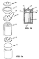
- Figs. 1a and 1b are graphical representations of the main components of a cylindrical power cell according to one embodiment of the present invention, with Fig. 1a showing an exploded view of the cell. Electrode and electrolyte layers are in cylindrical assembly 101 (also called a "jellyroll"). Negative collector disk 103 and positive collector disk 105 are attached to opposite ends of cylindrical assembly 101. The negative and positive collector disks function as internal terminals, with the negative collector disk electrically connected to the negative electrode and the positive collector disk electrically connected to the positive electrode. Cap 109 and can 113 are external terminals. Negative collector disk 103 includes tab 107 to connect the negative collector disk 103 to cap 109. Positive collector disk 105 is electrically connected to cap 113. The embodiment shown in Figs.
- a gasket 111 rests on a bead 115 and electrically insulates cap 109 from can 113.
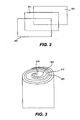
- Fig. 2 is a representation of electrode and separator layers prior to winding.
- Negative electrode 201 is separated from positive electrode 221 by separator 211.
- Negative electrode 201 includes a suitable electrochemically active zinc compound, typically zinc oxide and/or zinc metal, on a carrier sheet.
- Other electrochemically active zinc compounds such as calcium zincate may be used as well. As discussed above, zinc and zinc compounds are significantly less hazardous than the more commonly used cadmium compounds.
- the zinc oxide is a low carbonate zinc oxide.
- the presence of carbonate neutralizes the electrolyte and can impede high rate discharge.
- US Patent Application No. 10/921,062 J. Phillips
- filed August 17, 2004 (published as US 2005/0064292 ) describes manufacturing a low carbonate zinc electrode.
- the carbonate content in such compositions is preferably not greater than about 1 percent by weight.
- the negative electrode may include other materials that facilitate certain processes within the electrode such as ion transport, electron transport, wetting, porosity, structural integrity, active material solubility etc.
- the negative electrode includes another oxide such as bismuth oxide, indium oxide, and/or aluminum oxide. Bismuth oxide and indium oxide tend to mix with zinc and reduce gassing at the electrode.
- US Patent Application No. 10/921,062 (published as US 2005/0064292 ), referred to above, describes a method of manufacturing a negative electrode from a slurry containing additives in addition to zinc oxide.
- the slurry contains bismuth oxide, aluminum oxide, hydroxyethyl cellulose (HEC), and a dispersant.
- Indium oxide is also included in some embodiments.
- Various other formulations are possible, including those that employ other forms of zinc, such as calcium zincate or precursors thereof (e.g., calcium oxide and zinc oxide).
- Other electrode formulations include various inorganic fluorides, inorganic fibers such as alumina-silica fibers, and organic fibers such as cotton flock etc.
- Negative electrode additives in the above references include, for example, silica and fluorides of various alkaline earth metals, transition metals, heavy metals, and noble metals.
- the carrier for the negative electrode should be electrochemically compatible with the negative electrode materials.
- the carrier sheet can be provided in various structural forms including a perforated metal sheet, an expanded metal, and a metal foam. Among the criteria employed to select a particular structural form are cost, ease of coating, and ability to facilitate electron transport between the electrochemically active electrode material and the current collector.
- the carrier material is preferably copper or an alloy of copper in the form of a perforated sheet or an expanded metal.
- the current collector may be coated with a layer of tin, lead, or other material that is more compatible with zinc, in that it does not promote corrosion of zinc.
- the coating material has a high hydrogen evolution overpotential.
- These materials may be coated on the current collector by any of various means such as plating, dipping in molten metal, laminating, etc.
- the negative current collector is copper or a copper alloy coated with tin or a tin alloy to a thickness of between about 0.00005 and 0.001 inches (0.0013 and 0.025 mm).
- the thickness of the carrier is between about 2 and 5 mils (0.05 and 0.13 mm) for a perforated sheet but may be between 2 and 20 mils (0.05 and 0.51 mm) for expanded metal.
- Metal foam substrates may be between 15 and 60 mils (0.38 and 1.52 mm).
- the carrier is 3- 4 mils (0.08-0.10 mm) thick perforated copper.
- a specific range for the thickness of the negative electrode, including the carrier metal, zinc oxide and other negative electrode materials is about 10 to 24 mils (0.25 to 0.61 mm).
- Positive electrode 221 preferably has a composition similar to that employed to fabricate the nickel electrode in a conventional nickel cadmium battery, although there may be some important optimizations for the nickel zinc battery system.
- the electrochemically active material is preferably nickel hydroxide (Ni(OH) 2 ), although a nickel oxide or nickel oxyhydroxide may also be used.
- Zinc oxide and cobalt oxide may be employed in the positive electrode to improve charge transfer efficiency by creating conductive channels through the positive electrode materials.
- these oxides may be co-precipitated with or otherwise locked into the matrix of insoluble nickel material to prevent their leaching out of the positive electrode.
- cobalt metal is employed in the positive electrode, it is preferably present in a concentration of between about 1% to 10% by weight. This concentration range is appropriate for a wide range of discharge rates (e.g., about 0.001 to 0.4 ⁇ /cm 2 of zinc electrode surface area). In a typical high rate application (e.g., discharge is conducted at about 0.01 to 0.4 ⁇ /cm 2 of zinc electrode surface area), the concentration of cobalt metal is between about 4-10% by weight in the positive electrode. In a typical low rate application, the concentration of cobalt metal is between about 1-5% by weight, and the discharge is conducted at about 0.001 to 0.01 ⁇ /cm 2 of zinc electrode surface area. Additives may be provided in the electrolyte and/or the electrode to reduce the migration of cobalt.
- cobalt oxide may also (or alternatively) be added to the material to enhance conductivity. Note that in commercial nickel cadmium cells, free cobalt oxide is commonly employed in the positive electrode mixture.
- a nickel foam matrix is preferably used to support the electroactive nickel (e.g., Ni(OH) 2 ) electrode material.
- the electroactive nickel e.g., Ni(OH) 2
- commercially available nickel foam by Inco, Ltd. may be used.
- the diffusion path to the Ni(OH) 2 (or other electrochemically active material) through the nickel foam should be short for applications requiring high discharge rates. At high rates, the time it takes ions to penetrate the nickel foam is important.
- the width of the positive electrode, comprising nickel foam filled with the Ni(OH) 2 (or other electrochemically active material) and other electrode materials, should be optimized so that the nickel foam provides sufficient void space for the Ni(OH) 2 material while keeping the diffusion path of the ions to the Ni(OH) 2 through the foam short.
- the foam substrate thickness may be may be between 15 and 60 mils (0.38 and 1.52 mm).
- the thickness of the positive electrode, comprising nickel foam filled with the electrochemically active and other electrode materials ranges from about 16 - 24 mils (0.41-0.61 mm) In a particularly preferred embodiment, positive electrode is about 20 mils (0.51 mm) thick.
- the density of the nickel foam should be optimized to ensure that the electrochemically active material uniformly penetrates the void space of the foam.
- nickel foam of density ranging from about 300 - 500 g/m 2 is used. An even more preferred range is between about 350 - 500 g/m 2 .
- nickel foam of density of about 350 g/m 2 is used.
- the foam may be made less dense to ensure there is sufficient void space.
- a nickel foam density of about 350 g/m 2 and thickness ranging from about 16 - 18 mils (0.41-0.46 mm) is used.
- the positive electrode may be coated with a material to prevent it from spalling, flaking, or otherwise mechanically degrading.
- the coating may be a polymeric or elastomeric material in some embodiments. Examples include polyvinyl alcohol (PVA) and polystyrene sulfonates.
- PVA polyvinyl alcohol
- the coating may be applied by dipping in a solution containing the coating material, brushing on the material, or spraying a solution of the material etc.
- Methods of making electrodes include wet and dry processes. Wet processes are described in US Patent Application No. 10/921,062 (published as US 2005/0064292 ), referred to above. However, wet processes may introduce organic materials into the nickel foam matrix. The presence of these organic materials are undesirable as they reduce conductivity.
- the positive electrode is made by a dry process which does not employ substantial water or other liquid.
- the component materials of nickel hydroxide, nickel and cobalt powders are dry blended together with a suitable binder and are introduced into a hopper. A continuous strip of foam nickel is drawn through the powder while rotating brushes force material into the foam pores. A compression roller step sizes the foam to the appropriate porosity.
- Separator 211 serves to mechanically isolate the positive and negative electrodes, while allowing ionic exchange to occur between the electrodes and the electrolyte.
- the separator also blocks zinc dendrite formation.
- Dendrites are crystalline structures having a skeletal or tree-like growth pattern ("dendritic growth") in metal deposition. In practice, dendrites form in the conductive media of a power cell during the lifetime of the cell and effectively bridge the negative and positive electrodes causing shorts and subsequent loss of battery function.
- a separator will have small pores.
- the separator includes multiple layers.
- the pores and/or laminate structure may provide a tortuous path for zinc dendrites and therefore effectively bar penetration and shorting by dendrites.
- the porous separator has a tortuosity of between about 1.5 and 10, more preferably between about 2 and 5.
- the average pore diameter is preferably at most about 0.2 microns (0.2x10 -6 m), and more preferably between about 0.02 and 0.1 microns (0.02 and 0.1x10 -6 m).
- the pore size is preferably fairly uniform in the separator.
- the separator has a porosity of between about 35 and 55% with one preferred material having 45% porosity and a pore size of 0.1 micron (0.1x10 -6 m).
- the separator comprises at least two layers (and preferably exactly two layers) - a barrier layer to block zinc penetration and a wetting layer to keep the cell wet with electrolyte, allowing ionic exchange.
- Performance of the cell may be aided by keeping the positive electrode as wet as possible and the negative electrode relatively dry.
- the barrier layer is located adjacent to the negative electrode and the wetting layer is located adjacent to the positive electrode. This arrangement improves performance of the cell by maintaining electrolyte in intimate contact with the positive electrode.
- the wetting layer is placed adjacent to the negative electrode and the barrier layer is placed adjacent to the positive electrode. This arrangement aids recombination of oxygen at the negative electrode by facilitating oxygen transport to the negative electrode via the electrolyte.
- the barrier layer is typically a microporous membrane. Any microporous membrane that is ionically conductive may be used. Often a polyolefin having a porosity of between about 30 and 80 per cent, and an average pore size of between about 0.005 and 0.3 micron (0.005 and 0.3x10 -6 m) will be suitable.
- the barrier layer is a microporous polyethylene. Examples of commercially available materials for the barrier layer include the UBE U-PORE UP3138 (Ube Industries, Ltd., Tokyo, Japan), the SOLUPORETM products from Solutech of Heerlen, Netherlands, the CELGARDTM line of separators from Celgard Inc.
- the barrier layer is typically about 0.5 - 4 mils (0.013-0.11 mm) thick, more preferably between about 2 and 4 mils (0.051 and 0.11 mm) thick.
- Specific examples of barrier layer membranes include a 4 mil (0.11 mm) AMS separator, 2 layers of a 1 mil (0.025 mm) thick SOLUPORETM separator and 2 layers of 1 mil (0.025 mm) thick CELGARDTM separator.
- the wetting layer may be made of any suitable wettable separator material.
- the wetting layer has a relatively high porosity e.g., between about 50 and 85% porosity.
- examples include polyamide materials such as nylon-based as well as wettable polyethylene and polypropylene materials.
- the wetting layer is between about 1 and 10 mils (0.025 and 0.25 mm) thick, more preferably between about 3 and 6 mils (0.076 and 0.15 mm) thick.
- Examples of separate materials that may be employed as the wetting material include NKK VL100 (NKK Corporation, Tokyo, Japan), Freudenberg FS2213E, Scimat 650/45 (SciMAT Limited, Swindon, UK), and Vilene FV4365.
- nylon-based materials and microporous polyolefins are very often suitable.
- the separator may be treated with a surfactant prior to incorporating into the anode/cathode structure. This serves to enhance the wettability and promote uniform current density.
- the separator is first treated with a solution of .5 - 5% of a surfactant such as a Triton surfactant (e.g., X100) available from Dow Chemical Corporation of Midland Michigan.
- a surfactant such as a Triton surfactant (e.g., X100) available from Dow Chemical Corporation of Midland Michigan.
- Triton surfactant e.g., X100
- the time of contact with the surfactant as well as the drying time, choice of surfactant, and concentration of surfactant are all factors that can impact the effectiveness of the treatment. Soaking for several hours in a dilute aqueous solution and subsequent air-drying can produce excellent results; additionally the use of other solvents such as methanol has been found to accelerate the uptake of the surfactant.
- the separator serves as a "bag" for one of the electrode sheets, effectively encapsulating an electrode layer.
- encapsulating the negative electrode in a separator layer will aid in preventing dendrite formation.
- use of a barrier layer sheet without encapsulating an electrode is sufficient protection against dendrite penetration.
- Fig. 3 is a representation of electrode and separator layers in a cylindrical or jellyroll-like assembly.
- the jellyroll is formed from the cut electrode and separator sheets described above. Negative electrode 301 and positive electrode 321 are separated by separator 313.
- a winding apparatus draws the various sheets in at the same time and rolls them into the jellyroll-like structure. After a cylinder of sufficient thickness is produced, the apparatus cuts the layers of separator and electrodes to produce the finished cell assembly.
- a hollow core 315 extends through the center of the assembly. The radius and shape of the core may be controlled by the winding tool which holds the sheets of electrode and separator during winding.
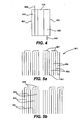
- Fig. 4 is a vertical cross-sectional representation of one set of electrode and separator layers in a cylindrical assembly. These layers are wound together in a spiral to form the jellyroll.
- a negative electrode 401 includes the electrochemically active material 403, e.g. zinc oxide, and any other negative electrode materials, and a current collector 405.
- a positive electrode 421 includes a current collector 423 (e.g., a nickel foam substrate in this embodiment) filled with Ni(OH) 2 and other positive electrode materials. Note that a metal tab 425 is attached the nickel foam positive current collector 423.
- Negative current collector 405 extends past separator 413 at one axial end of the assembly and positive current collector tab 425 extends past separator 413 at the other axial end.
- the carrier for the electrochemically active material in this embodiment serves as the negative current collector.
- the negative current collector is co-extensive with the other negative electrode materials at the positive end of the assembly.
- the negative current collector is copper of thickness of about 3 - 4 mils (0.076-0.11 mm).
- the positive current collector is typically nickel.
- the positive current collector tab 425 is a nickel strip of about 3 mils (0.076 mm) thickness spot-welded or otherwise attached to the nickel foam substrate.
- Fig. 5a shows a cross-sectional view of the negative end of a cylindrical assembly 510 prior to attaching the disk (e.g., collector disk 103 in Fig. 1A ) to the assembly according to one embodiment of the present invention, with negative electrode layers 501, separator layers 503, positive electrode layers 505 and negative current collectors 507.
- a negative collector disk is attached to the negative end of the cylindrical assembly and is electrically connected to the negative electrode via the current collectors.
- Fig. 5a shows one embodiment in which the current collectors 501 are bent at acute angles (e.g., about 90 degrees) prior to attaching the collector disk to form a substantially flat and continuous surface. Bending the current collectors increases the surface area available for attachment. It is important that the negative current collectors do not contact the positive electrode 505. In some embodiments, it may be necessary to cover or protect the ends of the positive electrode at the negative end of the cylindrical assembly.
- Fig. 5b shows another embodiment in which the bent current collectors are separated from the positive electrode by separator layers 503.
- the separator layers extend further than the positive electrodes at the negative end of the cylindrical assembly.
- negative and/or positive current collectors may be bent prior to attaching the collector disks, in a specific embodiment, only the negative current collectors are bent to improve attachment to the negative collector disk.
- the copper-to-copper contact presents particular challenges.
- configurations such as those shown in Figs. 5a and 5b are particularly desirable for the negative electrode.
- the current collectors may be bent toward the center of the assembly as shown in Fig. 5a , or facing one direction as shown if Fig. 5b .
- the current collectors may be predisposed in the desired direction before being pressed flat, e.g., by scoring at or near the bending point.
- the current collectors are predisposed to bending while being wound in the jellyroll.
- sections of the current collectors may be removed to create a saw-tooth or battlement configuration. This may be most conveniently done during the slitting process of individual electrode fabrication. The surface created provides for better attachment of the current collector and the collector disk, which improves reliability and lowers cell impedance.
- collector disks are conductivity, attachability to the current collectors, and allowing uniform distribution of electrolyte. The latter point can be understood by recognizing that electrolyte must normally be added after at least one of the current disks has been properly placed in the cell and attached to the electrode current collector.
- positive collector disks are perforated nickel disks.
- the disk (positive or negative) is slotted with radial open sections and associated vertical energy directors (extensions or protrusions) that make intimate contact with the edge of the spiral wound electrodes, or alternatively with the cap or can, in which case the flat portion of the disk is electrically connected with the wound electrodes.
- the vertical extensions may serve as a spring to help resist damage to the battery caused by shock or vibration, effectively allowing the electrode roll to "float" with respect to the can.
- Negative collector disks may be made of any material that will not corrode at the potential of the zinc electrode and may be electrically connected to the current collectors. The material should possess a high conductivity so that collector disk does not contribute a large impedance that reduces the power efficiency of the battery.
- the negative collector disk comprises a material selected from copper, a copper alloy, e.g. brass, and tin. These metals are preferred in part because they do not readily evolve hydrogen at the potential of the zinc electrode and they have low resistivity.
- the negative collector disk is copper or a copper alloy.
- Another embodiment employs tin coated copper or copper alloy.
- the collector disk serves as a spring, it may be made from a beryllium-copper alloy, a spring steel alloy, etc.
- the disk may be attached to the current collector by various methods known in the art such as spot welding, ultrasonic welding, laser welding, soldering, and other types of electro-conductive bonding appropriate for the terminal and current collector materials. While copper is favored in some embodiments for its low resistivity and other properties, it presents a particular challenge for attachment to the negative current collector of the jellyroll.
- a copper disk is typically attached to the copper current collectors by resistance welding or laser welding.
- the copper disk also comprises tin to improve attachability and reduce gassing.
- the bottom of the disk may be coated with tin or a tin alloy, which can serve as a solder bonding to the negative current collectors.
- the collector disk may also be brass. Brass collector disks are less conductive than copper but may have superior attachability.
- the entire jellyroll assembly is inserted into a retaining vessel, such as a can.
- electrolyte is then added to the cylindrical assembly.
- the disks should be shaped to allow electrolyte to enter the body of the cell and be evenly distributed through the cylindrical assembly as well as to allow attachment to the current collectors.
- the disks may or may not be perforated or slotted.
- the collector disks comprise H-shaped structures.
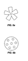
- Fig. 6a shows a collector disk that is a circular disk with a center hole and triangular notches or "cake slices" removed from the perimeter. The design shown in Fig. 6a has been found to be relatively easy to weld.
- Fig. 6a shows a collector disk that is a circular disk with a center hole and triangular notches or "cake slices" removed from the perimeter. The design shown in Fig. 6a has been found to be relatively easy to weld.
- Fig. 6a shows a collector disk that is a circular disk with a center hole and triangular not
- FIG. 6b shows a disk with holes spaced to permit uniform distribution of the electrolyte.
- Providing a collector disk that permits uniform electrolyte distribution becomes increasingly important as the amount of electrolyte used is decreased. Uniform distribution is important during fill as well as for reincorporation of any electrolyte that leaks out of the assembly during normal operation. For example, some electrolyte may make its way above the collector disk during operation and then must then find its way back into the jellyroll. When this occurs, the disk design may facilitate uniform distribution of the electrolyte as it flows back into the jellyroll.
- the holes may be uniformly spaced or otherwise arranged to optimize uniform distribution. For example, the holes may be spaced in a spiral arrangement so that they overlay the separator layers when the disk is attached to the electrode.
- the polarity of the cell is such that the cap is positive and the can or vessel is negative. That is, the positive electrode of the cell assembly is electrically connected with the cap and the negative electrode of the cell assembly is electrically connected with the can that retains the cell assembly. In a preferred embodiment of this invention, the polarity of the cell is opposite of that of a conventional cell. Thus, the negative electrode is electrically connected with the cap and the positive electrode is electrically connected to the can.
- the cap is a normally connected with the collector disk by a tab.
- the collector disk connected with the can is normally welded or otherwise attached to the can.
- Fig. 7a shows a perforated collector disk 701 with a U-shaped indent 703. Part of the U-shaped indented portion of the disk is attached to the can while the rest of the disk rests above the bottom of the can. In this way, the U-shaped portion functions as a spring that provides stability to the assembly if vibrated. In certain embodiments, the distance between the rest of the disk (i.e. the un-indented portion) and the bottom of the can is about 5 -10 mils (0.13-0.25 mm).
- electrolyte may be added prior to cap application and the cell is then spun to distribute the fluid.
- the electrolyte is introduced via an injection process in which electrolyte enters the cell via a fill port located in the base of the cell after the cap is applied.
- Fig. 7b shows positive collector disk 701 and negative collector disk 705 attached to cylindrical assembly 707 in can 709.
- Positive collector disk 701 has a U-shaped indent 703 attached to one end of can 709.
- positive collector disk 701 is perforated and negative collector disk 705 is a donut-shaped disk containing a center hole. Most of the electrolyte added through the center hole of the negative collector disk is then forced down the assembly, through the center hole of the positive disk to the bottom of the can where it is forced upward on the cell perimeter and then reaches the electrodes in the jellyroll assembly through the perforations in the positive collector disk.
- the structure or shape of remainder of the disk may be determined solely by attachability requirements.
- the surface of the remainder of the negative collector disk is unperforated to maximize the surface area available for attachment to the current collectors. See e.g., the disk structure in Fig. 6a .
- the negative collector disk is solid and the electrolyte is not added through the negative collector disk but only through the positive collector disk.
- This embodiment may require a fill port.
- a negative can design can be employed.
- the electrolyte should possess a composition that limits dendrite formation and other forms of material redistribution in the zinc electrode. Such electrolytes have generally eluded the art. But one that appears to meet the criterion is described in U.S. Patent No. 5,215,836 issued to M. Eisenberg on June 1, 1993 .
- a particularly preferred electrolyte includes (1) an alkali or earth alkali hydroxide present in an amount to produce a stoichiometric excess of hydroxide to acid in the range of about 2.5 to 11 equivalents per liter, (2) a soluble alkali or earth alkali fluoride in an amount corresponding to a concentration range of about 0.01 to 1 equivalents per liter of total solution, and (3) a borate, arsenate, and/or phosphate salt (e.g., potassium borate, potassium metaborate, sodium borate, sodium metaborate, and/or a sodium or potassium phosphate).
- a borate, arsenate, and/or phosphate salt e.g., potassium borate, potassium metaborate, sodium borate, sodium metaborate, and/or a sodium or potassium phosphate.
- the electrolyte comprises about 4.5 to 10 equiv/liter of potassium hydroxide, from about 2 to 6 equiv/liter boric acid or sodium metaborate and from about 0.01 to 1 equivalents of potassium fluoride.
- a specific preferred electrolyte for high rate applications comprises about 8.5 equiv/liter of hydroxide, about 4.5 equivalents of boric acid and about 0.2 equivalents of potassium fluoride.
- the invention is not limited to the electrolyte compositions presented in the Eisenberg patent. Generally, any electrolyte composition meeting the criteria specified for the applications of interest will suffice. Assuming that high power applications are desired, then the electrolyte should have very good conductivity. Assuming that long cycle life is desired, then the electrolyte should resist dendrite formation. In the present invention, the use of borate and/or fluoride containing KOH electrolyte along with appropriate separator layers reduces the formation of dendrites thus achieving a more robust and long-lived power cell.
- the electrolyte composition includes an excess of between about 3 and 5 equiv/liter hydroxide (e.g., KOH, NaOH, and/or LiOH).
- KOH equiv/liter hydroxide
- NaOH equiv/liter hydroxide
- LiOH equiv/liter hydroxide
- an appropriate electrolyte for calcium zincate has the following composition: about 15 to 25% by weight KOH, about 0.5 to 5.0% by weight LiOH.
- the electrolyte may comprise a liquid and a gel.
- the gel electrolyte may comprise a thickening agent such as CARBOPOL® available from Noveon of Cleveland, OH.
- a fraction of the active electrolyte material is in gel form.
- about. 5-25% by weight of the electrolyte is provided as gel and the gel component comprises about 1-2% by weight CARBOPOL®.
- Fig. 8 shows the positive end of a cylindrical assembly 801 and can 807 according to one embodiment of the present invention.
- a portion 803 of positive collector disk 805 is attached to the end of can 807 as described above with reference to Figs. 7a and 7b .
- Some of the electrolyte is in the form of a gel which serves as a non-spillable reservoir 809 for electrolyte that may decompose (e.g., through hydrogen evolution).
- electrolyte from reservoir 809 moves up through the perforated collector disk 805 to the cylindrical assembly as needed.
- the gel may be added to the cylindrical assembly before, during or after the liquid electrolyte is added.
- the liquid electrolyte is added through the center hole of the negative collector disk.
- Liquid electrolyte travels down the center portion the assembly, under the positive collector disk and wicks up through the perforated collector disk to uniformly fill the assembly. Gel electrolyte is then added through the center hole in the negative collector disk, displacing liquid electrolyte remaining in the center of the assembly or base.
- the can or other vessel serves as the outer housing or casing of the final cell.
- the can is often nickel-plated steel.
- the can may either be positive or negative.
- the can material may be a composition similar to that employed in a conventional nickel cadmium battery, such as steel, as long as the material is coated with another material compatible with the potential of the zinc electrode.
- the can is coated with a zinc-compatible material such as copper to prevent corrosion.
- the can is positive and the cap negative.
- the can may be a composition similar to that used in convention nickel-cadmium cells, typically nickel-plated steel.
- the interior of the can may be coated with a material to aid hydrogen recombination. Any material that catalyzes hydrogen recombination may be used. An example of such a material is silver oxide.
- the vessel is sealed to isolate the electrodes and electrolyte from the environment as shown in Fig 1b .
- the cylindrical assembly or jellyroll 101 is located inside can 113.
- Positive collector disk 105 is welded or otherwise attached to can 113 as discussed above with respect to Figs. 7a and 7b .
- Negative collector disk 103 is electrically connected to cap 109 through tab 107.
- Cap 109 is electrically isolated from can 113 through the use of flexible gasket 111. Gasket 111 resides on a circumferential bead 115 in the upper portion of can 113.
- the bead 115 on which gasket 111 rests is coated with a polymer coating.
- the gasket may be any material that electrically isolates the cap from the can. Preferably the material does not appreciably distort at high temperatures; one such material is nylon. In other embodiments, it may be desirable to use a less wettable material to reduce the driving force that causes the alkaline electrolyte to creep and ultimately leak from the cell at seams or other available egress points.
- An example of a less wettable material is polypropylene.
- the gasket is typically sealed by a crimping process.
- the gasket a sealing agent is used to prevent leakage.
- suitable sealing agents include bituminous sealing agents, tar and VERSAMID® available from Cognis of Cincinnati, OH.
- the cap may be made of any suitable conductive material that inhibits the evolution of hydrogen. These may include tin plated or silver plated steel. In a preferred embodiment, the cap is tin plated steel.
- Fig. 9 presents a representation of a cylindrical cell during electrolyte fill.
- Tab 901 electrically connects collector disk 903.
- tab 911 is long enough to allow cap 909 to be open during the filling process. Because of its length, it is important to use a highly conductive material for tab 901 to minimize impedance.
- cap 909 is negative and tab 901 is made of a highly conductive material such as copper.
- the cap is positive and the conductive paths typically comprise nickel.
- the cell may be, in some embodiments, permitted to vent gases from the battery that are generated during charge and discharge.
- a typical nickel cadmium cell vents gas at approximately 200 PSI (1.38 MPa).
- a nickel zinc cell of this invention is designed to operate at this pressure and even higher (e.g., up to about 300 PSI (2.07 MPa)) without the need to vent. This may encourage recombination of any oxygen and hydrogen generated within the cell.
- the cell is constructed to maintain an internal pressure of not greater than about 600 PSI (4.14 MPa) and more preferably not greater than about 450 PSI (3.10 MPa).
- a nickel zinc cell is designed to vent gas at relatively lower pressures. This may be appropriate when the design encourages release of hydrogen and/or oxygen gases over their recombination within the nickel zinc cell.
- Fig. 10 is a representation of a cap and vent mechanism according to one embodiment of the invention.
- the vent mechanism is preferably designed to allow gas escape but not allow electrolyte passage that may interfere with the reproducible function of the vent and raise safety concerns.
- Cap 1001 includes disk 1008 that rests on the gasket, vent 1003 and upper portion 1005.
- Disk 1008 includes a hole 1007 that permits gas to escape.
- Vent 1003 covers hole 1007 and is displaced by escaping gas.
- Vent 1003 is typically rubber, though it may be made of any material that permits gas to escape and withstands high temperatures. A square vent has been found to work well.
- Upper portion 1005 is welded to disk 1008 at weld spots 1009 and includes holes 1011 to allow the gas to escape.
- the vent mechanism includes a vent cover 1013 made of a hydrophobic gas permeable membrane.
- vent cover materials include microporous polypropylene, microporous polyethylene, microporous PTFE, microporous FEP, microporous fluoropolymers, and mixtures and co-polymers thereof (see e.g., US Patent Application No. 10/098,193 (published as US 2003/0175582 ), "Leak Proof Pressure Relief Valve for Secondary Batteries," filed March 15, 2002 for J. Phillips ).
- the material should be able to withstand high temperatures.
- Hydrophobic gas permeable membranes may be used alone or in conjunction with a tortuous gas escape route. Many other battery venting mechanisms are known in the art and are suitable for use with this invention.
- a cell's materials of construction are chosen to provide regions of hydrogen egress.
- the cells cap or gasket may be made from a hydrogen permeable polymeric material.
- the outer annular region of the cell's cap is made from a hydrogen permeable material such as an acrylic plastic or one or more of the polymers listed above. Only the actual terminal (provided in the center of the cap and surrounded by the hydrogen permeable material) need be electrically conductive.
- the battery cells of this invention can have any of a number of different shapes and sizes.
- cylindrical cells of this invention may have the diameter and length of conventional AAA cells, AA cells, A cells, C cells, etc. Custom cell designs are appropriate in some applications.
- the cell size is a sub-C cell size of diameter 22 mm and length 43 mm.
- the profile of a battery pack for, e.g., a power tool will dictate the size and shape of the battery cells.
- This invention also pertains to battery packs including one or more nickel zinc battery cells of this invention and appropriate casing, contacts, and conductive lines to permit charge and discharge in an electric device.
- Nickel zinc battery designs must take into account several design considerations. Some apply to conventional NiCd or other battery designs, but require designs optimized for NiZn cells, and some challenges are unique to NiZn batteries. The present invention addresses these issues as discussed below.
- the battery design should minimize leaking of caustic electrolyte from the cell. Electrolyte leakage may minimized by operating at starved conditions (i.e. low amount of electrolyte). Thus, in some embodiments of the present invention, battery cells are provided that are capable of operating at starved conditions. As discussed below, operating at starved conditions presents design considerations that the NiZn batteries of the present invention address. Regardless of whether a cell is operated under starved conditions, electrolyte leakage may be further minimized by providing a liquid impermeable/gas permeable vent cover as discussed above with reference to Fig 10 .
- the electrolyte is uniformly distributed through the separator layer. Uniform electrolyte distribution is desirable as it provides uniform current density and thereby helps minimize shape change of the zinc electrode. Uniform distribution is especially important for starved cells.
- uniform electrolyte distribution is facilitated by providing collector disks with uniformly spaced holes through which the electrolyte is added to the cell.
- the negative collector disk may be unperforated except for a center hole through which electrolyte is added and the positive collector uniformly perforated to provide uniform distribution.
- the electrolyte is added through the center hole in the negative collector disk and is then reaches the cylindrical assembly or jellyroll from the holes in the perforated positive collector disk.
- a gel reservoir is added to replenish the electrolyte supply as needed as discussed above with respect to Fig. 7 .
- the relatively negative electric potential of zinc in zinc electrodes makes it particularly susceptible to hydrogen evolution and corrosion of the negative electrode. In particular, it is more susceptible to hydrogen evolution than cadmium and metal hydride cells. Hydrogen evolution is undesirable because of electrode corrosion, pressure build-up in the cell and potential cell dry-out through electrolyte decomposition. In addition, recombination of hydrogen and oxygen is challenging in a nickel zinc battery. In nickel - cadmium cells, in which dendrite formation is not a great concern, there is a clear path through the separator for gases to travel between electrodes for the recombination reaction. Unlike with conventional nickel cadmium or nickel metal hydride cells, the nickel zinc cells of the present invention may include a barrier separator layer that blocks zinc dendrite formation. This barrier layer prevents a clear path for evolved oxygen and hydrogen to access the appropriate recombination electrode in the cell. The gases instead must go around the jellyroll assembly to recombine.
- the batteries of the present invention may be designed to minimize hydrogen evolution at the zinc electrode.
- the negative electrode may include materials that reduce gassing at the negative electrode, such as certain metal oxides.
- the nickel zinc battery design facilitates recombination.
- recombination in the nickel zinc battery design of the present invention is hindered by the existence of a barrier layer to prevent zinc dendrite penetration.
- a catalyst for recombination may be added to the electrodes and/or interior of the can to aid recombination.
- An example of such a catalyst for hydrogen recombination is silver oxide.
- a catalyst such as bismuth is added to the negative electrode to facilitate oxygen recombination.
- the batteries of the present invention are suitable for operating at starved conditions.
- the separator layer comprises a barrier layer and a wetting layer.
- the wetting layer is adjacent to the zinc electrode. The more open pore-structure of the wetting vs. barrior layer facilitates oxygen transport to the zinc electrode for recombination.
- the oxygen recombination rate in a sub-C cell is at least 150 mA.
- zinc electrodes are susceptible to shape change. During charge/discharge cycling, formation of soluble zincate ion causes redistribution of zinc over the face of the electrode. Shape change results in a dramatic decrease in battery capacity with successive cycles.
- zinc electrodes are susceptible to zinc dendrites. Dendrites are crystalline structures having a skeletal or tree-like growth pattern ("dendritic growth") in metal deposition. During cycling, dendrites form in the zinc electrode and, if unchecked, penetrate the separator and reach the positive electrode causing shorts and subsequent loss of battery function.
- the batteries of the present invention include an electrolyte of a composition that limits dendrite formation and other forms of material redistribution in the zinc electrode as discussed above.
- the separator layer includes a barrier layer to impede dendrite formation and penetration.
- the presence of carbon dioxide in the battery cell neutralizes the alkaline electrolyte and can impede high rate discharge through formation of carbonate.
- many commercial sources of zinc oxide have significant carbonate content.
- zinc employed to fabricate the negative electrode has a relatively low-carbonate content, e.g., not more than 1% by weight.
- carbonate may form during wet processing using organic compounds.
- the positive electrode is formed by a dry-pmcessing method.
- the amount of electrolyte in the cell may be required to be boosted to account for electrolyte that is taken out of solution by a certain amount of carbonate.
- Copper and copper alloys are particularly preferred materials for the conductive paths associated with the zinc electrode. Copper is preferred because of its low resistivity, relatively low price, and electrochemical compatibility with the zinc electrode. Notably, nickel plated steel is the conductive path for the cadmium electrode in commercial nickel cadmium cells.
- the polarity of the nickel zinc cell is opposite that of a conventional power cell, that is the cap of the nickel zinc cell is negative and the can positive.
- a conventional power cell that is the cap of the nickel zinc cell is negative and the can positive.
- Approximately 0.5 m ⁇ of the overall impedance in a conventional C size power cell may be attributed to the positive current collector and the resistance weld to the cap. This is due in part to the compositional requirements of the terminal given the electrochemistry of conventional power cells.
- the use of copper in the manner described results in a significant impedance reduction at the now negative terminal thus achieving a more power efficient cell.
- the electrical attachment of the collector disk with the negative electrode requires specific manufacturing techniques.
- the copper collector is perforated and attached at multiple points along the negative electrode so that the electrode is attached to the current collector at multiple points along its length. By activating a greater area, the charge efficiency is further enhanced. The perforations also serve to locate the electrode and allow electrolyte to penetrate the stack uniformly during the electrolyte fill operation.
- the collector disk is slotted to achieve the named advantages.
- the copper collector disk requires only center hole for the electrolyte to enter. The structure of the rest of the disk is then determined by the requirements of the method of attachment (i.e. unperforated, perforated or slotted as required).
- the copper collector disk is covered with tin or a tin alloy and attached to the current collectors by soldering.
- the current collectors are bent as described above with reference to Fig. 4a to improve attachment of the collector disk to the current collectors.
- the spring may be a steel spring that has been plated with copper, tin, or another protective metal that has high hydrogen overpotential.
- the spring may be substituted for with a pressurized rubber annulus or "o" ring that is resistant to the alkaline media.
- Such materials may be EPDM (Ethylene Propylene Diene Monomer) or Viton® (fluoroelastomer family from DuPont Dow Elastomers, L.L.C.). In either case sufficient pressure is maintained such that low impedance electrical resistance is maintained between the cap and jellyroll.
- the pressure exerted by the o-ring presses downward through or from a crimp in the cell can. In some cases, it is desirable to provide a reinforced bottom of the can.
- the contact surface may be two interconnected nickel disks that are pressurized by a similar spring arrangement.
- the disks may be electroplated with cobalt
- the cobalt oxides provide much better conductivity than nickel oxides.
- the battery cells of the present invention have low overall impedance, due in part to the negative cap arrangement discussed above.
- a nickel-zinc sub-C cell has an overall AC impedance of between about 3 and 5 m ⁇ .
- the cell has an AC impedance of between about 3.5 and 4.5 m ⁇ .
- the overall AC impedance of Sanyo's power tool sub-C cell NiCd battery is 5.3 m ⁇ .
Landscapes
- Chemical & Material Sciences (AREA)
- Chemical Kinetics & Catalysis (AREA)
- Electrochemistry (AREA)
- General Chemical & Material Sciences (AREA)
- Engineering & Computer Science (AREA)
- Manufacturing & Machinery (AREA)
- Materials Engineering (AREA)
- Cell Electrode Carriers And Collectors (AREA)
- Secondary Cells (AREA)
- Battery Electrode And Active Subsutance (AREA)
- Primary Cells (AREA)
- Hybrid Cells (AREA)
- Cell Separators (AREA)
- Sealing Battery Cases Or Jackets (AREA)
Applications Claiming Priority (2)
| Application Number | Priority Date | Filing Date | Title |
|---|---|---|---|
| US11/116,113 US8703330B2 (en) | 2005-04-26 | 2005-04-26 | Nickel zinc battery design |
| PCT/US2006/015807 WO2006116496A2 (en) | 2005-04-26 | 2006-04-25 | Nickel zinc battery design |
Publications (2)
| Publication Number | Publication Date |
|---|---|
| EP1878072A2 EP1878072A2 (en) | 2008-01-16 |
| EP1878072B1 true EP1878072B1 (en) | 2011-07-27 |
Family
ID=36838523
Family Applications (1)
| Application Number | Title | Priority Date | Filing Date |
|---|---|---|---|
| EP06758626A Active EP1878072B1 (en) | 2005-04-26 | 2006-04-25 | Nickel zinc battery design |
Country Status (7)
| Country | Link |
|---|---|
| US (1) | US8703330B2 (zh) |
| EP (1) | EP1878072B1 (zh) |
| JP (1) | JP5258554B2 (zh) |
| CN (1) | CN101208818B (zh) |
| AT (1) | ATE518264T1 (zh) |
| CA (1) | CA2605458A1 (zh) |
| WO (1) | WO2006116496A2 (zh) |
Families Citing this family (38)
| Publication number | Priority date | Publication date | Assignee | Title |
|---|---|---|---|---|
| US7550230B2 (en) | 2001-03-15 | 2009-06-23 | Powergenix Systems, Inc. | Electrolyte composition for nickel-zinc batteries |
| US7833663B2 (en) * | 2003-08-18 | 2010-11-16 | Powergenix Systems, Inc. | Method of manufacturing nickel zinc batteries |
| US20140030567A1 (en) * | 2005-04-26 | 2014-01-30 | Powergenix Systems, Inc. | Heat sealing separators for nickel zinc cells |
| US8703330B2 (en) | 2005-04-26 | 2014-04-22 | Powergenix Systems, Inc. | Nickel zinc battery design |
| US9142835B2 (en) * | 2007-11-20 | 2015-09-22 | Sekisui Specialty Chemicals America, Llc | Separator film for batteries including oxidation resistant vinyl alcohol copolymer |
| JP5599384B2 (ja) * | 2008-04-02 | 2014-10-01 | パワージェニックス システムズ, インコーポレーテッド | 陰性缶を有する円筒形ニッケル─亜鉛セル |
| JP5564768B2 (ja) * | 2008-07-30 | 2014-08-06 | 日産自動車株式会社 | 電気化学デバイス |
| DE102008043808A1 (de) * | 2008-11-18 | 2010-05-20 | Robert Bosch Gmbh | Batterie |
| US8501351B2 (en) | 2009-05-18 | 2013-08-06 | Powergenix Systems, Inc. | Pasted zinc electrode for rechargeable nickel-zinc batteries |
| US9947919B2 (en) | 2009-08-07 | 2018-04-17 | Zincfive Power, Inc. | Carbon fiber zinc negative electrode |
| CN102484279B (zh) * | 2009-09-08 | 2015-06-17 | 鲍尔热尼系统公司 | 镍锌电池的热密封隔膜 |
| JP5559334B2 (ja) * | 2009-09-25 | 2014-07-23 | 湖南科力▲遠▼新能源股▲分▼有限公司 | 円筒形電池 |
| EP2489086B1 (en) * | 2009-10-13 | 2021-12-08 | ZincFive Power, Inc. | Cylindrical nickel-zinc cell with positive can |
| US20120171535A1 (en) * | 2010-12-31 | 2012-07-05 | Fuyuan Ma | Nickel-zinc battery and manufacturing method thereof |
| CN104362391B (zh) * | 2011-05-09 | 2017-08-04 | 杭州新研动力能源有限公司 | 镍锌电池及其制造方法 |
| CN104067437B (zh) | 2012-02-06 | 2015-06-17 | 日本碍子株式会社 | 锌二次电池 |
| CN104519771B (zh) | 2012-03-20 | 2018-12-07 | 翠科有限公司 | 一种贩卖系统及方法 |
| WO2013165597A1 (en) * | 2012-05-04 | 2013-11-07 | Tricopan Llc | System and method for identifying batteries |
| US9337683B2 (en) | 2012-12-20 | 2016-05-10 | Powergenix Systems, Inc. | Controlling battery states of charge in systems having separate power sources |
| DE212012000292U1 (de) | 2012-12-20 | 2015-07-23 | Powergenix Systems, Inc. | Steuerung von Batterieladezuständen bei Systemen mit getrennten Stromquellen |
| CN104282952B (zh) * | 2013-07-12 | 2021-03-16 | 苏州宝时得电动工具有限公司 | 电解液及电池 |
| CN104282910A (zh) * | 2013-07-12 | 2015-01-14 | 苏州宝时得电动工具有限公司 | 电池 |
| EP3486992B1 (en) * | 2013-06-28 | 2020-09-23 | Positec Power Tools (Suzhou) Co., Ltd | Battery |
| CN104253283A (zh) * | 2013-06-28 | 2014-12-31 | 苏州宝时得电动工具有限公司 | 电池 |
| US10529973B2 (en) | 2013-08-22 | 2020-01-07 | Tricopian, Llc | Standardized rechargeable battery cell |
| DE102014201160A1 (de) * | 2014-01-23 | 2015-07-23 | Robert Bosch Gmbh | Batteriezelle mit mindestens einem Elektrodenensemble |
| WO2016045622A1 (zh) | 2014-09-26 | 2016-03-31 | 苏州宝时得电动工具有限公司 | 电池、电池组和不间断电源 |
| JP2016152082A (ja) * | 2015-02-16 | 2016-08-22 | 株式会社日本触媒 | アニオン伝導性膜及びその製造方法 |
| US10403903B2 (en) * | 2016-06-10 | 2019-09-03 | Greatbatch Ltd. | Low-rate battery design |
| WO2017221451A1 (ja) * | 2016-06-24 | 2017-12-28 | 日本碍子株式会社 | 層状複水酸化物を含む機能層及び複合材料 |
| US10396315B2 (en) | 2016-12-30 | 2019-08-27 | Microsoft Technology Licensing, Llc | Hollow-core rolled-electrode battery cell |
| CA2997725C (en) | 2017-03-10 | 2021-08-03 | Evolution Engineering Inc. | Battery coil engaging members for downhole tools |
| WO2019071239A1 (en) * | 2017-10-06 | 2019-04-11 | Farady&Future Inc. | DENSES ENERGY STORAGE SYSTEMS |
| KR102173032B1 (ko) | 2017-11-13 | 2020-11-02 | 주식회사 엘지화학 | 전극조립체 및 그 제조방법 |
| US20210399305A1 (en) * | 2018-10-24 | 2021-12-23 | Urban Electric Power Inc. | A protective barrier layer for alkaline batteries |
| KR102493916B1 (ko) * | 2018-11-28 | 2023-02-01 | 주식회사 엘지에너지솔루션 | 캡조립체, 이차전지 및 그의 제조방법, 전지팩 |
| DE102018131928A1 (de) | 2018-12-12 | 2020-06-18 | Carl Freudenberg Kg | Separator für elektrochemische Energiespeicher und Wandler |
| JP7251686B2 (ja) * | 2020-03-06 | 2023-04-04 | 株式会社村田製作所 | 二次電池、電子機器及び電動工具 |
Family Cites Families (103)
| Publication number | Priority date | Publication date | Assignee | Title |
|---|---|---|---|---|
| US3089856A (en) * | 1960-11-10 | 1963-05-14 | New Jersey Zinc Co | Production of conductive zinc oxide |
| US3287166A (en) * | 1965-01-27 | 1966-11-22 | Douglas Aircraft Co Inc | Battery electrode and battery, and process for preparing said electrode |
| US3287164A (en) * | 1965-01-27 | 1966-11-22 | Douglas Aircraft Co Inc | Electrode and battery |
| US3348976A (en) * | 1965-03-30 | 1967-10-24 | Mallory Battery Canada | Self-supporting sintered zinc anode structure |
| US3558356A (en) * | 1967-02-28 | 1971-01-26 | Texas Instruments Inc | Nickel-zinc battery system which is negative limited during charging thereof |
| US3432351A (en) * | 1968-01-02 | 1969-03-11 | Union Carbide Corp | Process for producing electrodes for galvanic batteries |
| US3669746A (en) * | 1970-08-03 | 1972-06-13 | Gates Rubber Co | Separators for secondary alkaline batteries having a zinc-containing electrode |
| US3870564A (en) * | 1973-03-30 | 1975-03-11 | Tokyo Shibaura Electric Co | Alkaline cell |
| JPS5461B2 (zh) * | 1973-11-21 | 1979-01-05 | ||
| US3923544A (en) * | 1974-03-11 | 1975-12-02 | Electrochem Inc | Zinc electrode and method of making same |
| US3898099A (en) * | 1974-03-18 | 1975-08-05 | Energy Res Corp | Hydrophilic electrode and method for making the same |
| CS167146B1 (zh) * | 1974-05-21 | 1976-04-29 | ||
| JPS5626108B2 (zh) * | 1975-01-20 | 1981-06-16 | ||
| DE2542459A1 (de) * | 1975-09-24 | 1977-04-07 | Varta Batterie | Gas- und fluessigkeitsdichter akkumulator |
| US4130696A (en) * | 1976-09-09 | 1978-12-19 | Yardney Electric Corporation | Conductive diluent for pressed nickel electrodes |
| US4118860A (en) * | 1977-01-27 | 1978-10-10 | Polaroid Corporation | Method of making a flat battery |
| US4091181A (en) * | 1977-09-01 | 1978-05-23 | Union Carbide Corporation | Rechargeable galvanic cell |
| DE2803151A1 (de) | 1978-01-25 | 1979-07-26 | Varta Batterie | Verfahren zur herstellung positiver ni(oh) tief 2 -presselektroden |
| DE3068808D1 (en) * | 1979-10-03 | 1984-09-06 | Lucas Ind Plc | A nickel electrode, a method of producing the nickel electrode and an electrochemical cell employing the nickel electrode |
| JPS606073B2 (ja) * | 1979-11-07 | 1985-02-15 | 松下電器産業株式会社 | 渦巻電極体を備えた電池の製造法 |
| US4304828A (en) * | 1980-06-27 | 1981-12-08 | Energy Research Corporation | Zinc electrode |
| FR2485816A1 (fr) * | 1980-06-30 | 1981-12-31 | Accumulateurs Fixes | Ensemble generateur electrochimique et fils de sortie de courant |
| US4298662A (en) * | 1980-07-31 | 1981-11-03 | General Electric Company | Resealable vent valve for containers such as batteries |
| US4273841A (en) * | 1980-08-14 | 1981-06-16 | General Electric Company | Ternary electrolyte for secondary electrochemical cells |
| US4327157A (en) * | 1981-02-20 | 1982-04-27 | The United States Of America As Represented By The Secretary Of The Navy | Stabilized nickel-zinc battery |
| US4552821A (en) * | 1983-06-30 | 1985-11-12 | Duracell Inc. | Sealed nickel-zinc battery |
| US4554227A (en) * | 1983-07-18 | 1985-11-19 | Japan Storage Battery Company Limited | Alkaline battery |
| DE3520108A1 (de) | 1985-06-05 | 1986-12-11 | Varta Batterie Ag, 3000 Hannover | Positive sammlerelektrode fuer akkumulatoren mit alkalischem elektrolyten |
| DE3922596A1 (de) | 1989-07-10 | 1991-01-24 | Varta Batterie | Galvanisches element |
| US5300371A (en) * | 1990-03-23 | 1994-04-05 | Battery Technologies Inc. | Manganese dioxide positive electrode for rechargeable cells, and cells containing the same |
| US5168018A (en) | 1990-05-17 | 1992-12-01 | Matsushita Electric Industrial Co., Ltd. | Method of manufacturing zinc-alkaline batteries |
| US5124120A (en) * | 1990-07-16 | 1992-06-23 | Cominco Ltd. | Method for making zinc electrodes for alkaline-zinc batteries |
| US5856040A (en) * | 1991-03-21 | 1999-01-05 | Duracell, Inc. | Alkaline cell |
| US5215836A (en) * | 1991-07-18 | 1993-06-01 | Electrochimica Corporation | Alkaline galvanic cells |
| CN1076882A (zh) | 1992-03-27 | 1993-10-06 | 冶金工业部攀枝花钢铁公司密地机械厂 | 齿轮传动件加载跑合方法及其装置 |
| JP3032925B2 (ja) * | 1992-09-25 | 2000-04-17 | 富士写真フイルム株式会社 | 非水電池 |
| US5545492A (en) * | 1992-10-14 | 1996-08-13 | National Power Plc | Electrochemical apparatus for power delivery utilizing an air electrode |
| JPH06283194A (ja) * | 1993-03-29 | 1994-10-07 | Yuasa Corp | 密閉形アルカリ亜鉛蓄電池 |
| JPH07130341A (ja) * | 1993-11-02 | 1995-05-19 | Fuji Photo Film Co Ltd | 非水電池 |
| US5626988A (en) * | 1994-05-06 | 1997-05-06 | Battery Technologies Inc. | Sealed rechargeable cells containing mercury-free zinc anodes, and a method of manufacture |
| US5521021A (en) * | 1994-07-06 | 1996-05-28 | Alexander Manufacturing Corporation | Electric vehicle cell |
| US5604054A (en) * | 1994-07-13 | 1997-02-18 | Rayovac Corporation | Reduced environmental hazard LeClanche cell having improved performance ionically permeable separator |
| US5556720A (en) | 1994-08-18 | 1996-09-17 | Energy Research Corporation | Sealed zinc secondary battery and zinc electrode therefor |
| US6025094A (en) * | 1994-11-23 | 2000-02-15 | Polyplus Battery Company, Inc. | Protective coatings for negative electrodes |
| US5707756A (en) * | 1994-11-29 | 1998-01-13 | Fuji Photo Film Co., Ltd. | Non-aqueous secondary battery |
| JP3370486B2 (ja) * | 1995-07-21 | 2003-01-27 | 松下電器産業株式会社 | アルカリ電池 |
| US5741606A (en) * | 1995-07-31 | 1998-04-21 | Polystor Corporation | Overcharge protection battery vent |
| CN1134078C (zh) * | 1995-08-28 | 2004-01-07 | 旭化成株式会社 | 新型电池及其制造方法 |
| US5766789A (en) * | 1995-09-29 | 1998-06-16 | Energetics Systems Corporation | Electrical energy devices |
| US5773176A (en) * | 1995-10-04 | 1998-06-30 | Yardney Technical Products, Inc. | Rechargeable alkaline silver-zinc cell with improved negative electrode |
| JP3527594B2 (ja) * | 1995-11-16 | 2004-05-17 | 松下電器産業株式会社 | アルカリ蓄電池およびその製造法 |
| US5607796A (en) * | 1996-06-24 | 1997-03-04 | Rayovac Corporation | Rechargeable alkaline electrochemical cell |
| US6261720B1 (en) | 1996-09-20 | 2001-07-17 | Matsushita Electric Industrial Co., Ltd. | Positive electrode active material for alkaline storage batteries |
| FR2754393A1 (fr) * | 1996-10-03 | 1998-04-10 | Accumulateurs Fixes | Dispositif d'introduction et de maintien d'un faisceau d'electrodes dans un conteneur de generateur electrochimique |
| US5863676A (en) * | 1997-03-27 | 1999-01-26 | Energy Research Corporation | Calcium-zincate electrode for alkaline batteries and method for making same |
| US6287719B1 (en) * | 1998-06-15 | 2001-09-11 | Eveready Battery Company, Inc. | Battery including a non-aqueous multi-cell spiral-wound electrode assembly |
| ATE224586T1 (de) * | 1999-03-04 | 2002-10-15 | Greatbatch W Ltd | Gewickelte hochleistungsbatterie |
| JP3432171B2 (ja) | 1999-04-26 | 2003-08-04 | エヌイーシートーキン株式会社 | 非水電解液二次電池 |
| FR2796496A1 (fr) | 1999-07-15 | 2001-01-19 | Cit Alcatel | Electrode au zinc pour generateur electrochimique a electrolyte alcalin |
| CA2281371A1 (en) * | 1999-09-03 | 2001-03-03 | Waltraud Taucher-Mautner | Rechargeable nickel-zinc cell |
| EP1134819B1 (en) * | 2000-03-14 | 2007-04-25 | Sanyo Electric Co., Ltd. | Nonaqueous electrolyte secondary cells |
| US6653018B2 (en) | 2000-03-17 | 2003-11-25 | Tdk Corporation | Electrochemical device |
| US6368365B1 (en) * | 2000-03-23 | 2002-04-09 | The Gillette Company | Method of making a battery |
| JPWO2002023663A1 (ja) * | 2000-09-11 | 2004-01-29 | 松下電器産業株式会社 | アルカリ亜鉛二次電池およびその製造方法 |
| JP3943822B2 (ja) | 2000-10-26 | 2007-07-11 | 功 松本 | 電池用渦巻状電極群及び電池 |
| CA2325640A1 (en) * | 2000-11-10 | 2002-05-10 | Jeffrey Phillips | Positive and negative interactive electrode formulation for a zinc-containing cell having an alkaline elelctrolyte |
| US7829221B2 (en) * | 2000-11-10 | 2010-11-09 | Powergenix Systems, Inc. | Cobalt containing positive electrode formulation for a nickel-zinc cell |
| CA2325308A1 (en) * | 2000-11-10 | 2002-05-10 | Jeffrey Phillips | Negative electrode formulation for a low toxicity zinc electrode having additives with redox potentials negative to zinc potential |
| CA2325791A1 (en) * | 2000-11-10 | 2002-05-10 | Jeffrey Phillips | Negative electrode formulation for a low toxicity zinc electrode having additives with redox potentials positive to zinc potential |
| CA2325595A1 (en) * | 2000-11-10 | 2002-05-10 | Jeffrey Phillips | Charger for a rechargeable nickel-zinc battery |
| US6740446B2 (en) * | 2001-02-28 | 2004-05-25 | Ovonic Battery Company, Inc. | Electrochemical cell with zigzag electrodes |
| US7550230B2 (en) * | 2001-03-15 | 2009-06-23 | Powergenix Systems, Inc. | Electrolyte composition for nickel-zinc batteries |
| US6949310B2 (en) * | 2001-03-15 | 2005-09-27 | Powergenix Systems, Inc. | Leak proof pressure relief valve for secondary batteries |
| CA2377062A1 (en) * | 2001-03-15 | 2002-09-15 | Powergenix Systems Inc. | Alkaline cells having positive nickel hydroxide electrodes with fluoride salt additives |
| CA2377065A1 (en) * | 2001-03-15 | 2002-09-15 | Powergenix Systems Inc. | Alkaline cells having low toxicity rechargeable zinc electrodes |
| US6977124B2 (en) * | 2001-07-19 | 2005-12-20 | Wilson Greatbatch Technologies, Inc. | Contoured casing for an electrochemical cell |
| US6620543B2 (en) * | 2001-08-09 | 2003-09-16 | Eveready Battery Company, Inc. | Electrochemical cell having can vent and cover terminal |
| US6617072B2 (en) * | 2001-11-27 | 2003-09-09 | Ovonic Battery Company, Inc. | Positive active electrode composition with graphite additive |
| US20030113630A1 (en) * | 2001-12-06 | 2003-06-19 | Kainthla Ramesh C. | Anodic zinc electrode for use in an alkaline based electrochemical cell |
| CA2380952A1 (en) | 2002-04-08 | 2003-10-08 | Jeffrey Phillips | High rate, thin film, bipolar nickel zinc battery having oxygen recombination facility |
| JP4562984B2 (ja) | 2002-12-27 | 2010-10-13 | 東芝電池株式会社 | 密閉型アルカリ一次電池 |
| US7195839B2 (en) * | 2003-02-11 | 2007-03-27 | Eveready Battery Company, Inc. | Battery cell with improved pressure relief vent |
| CN1283022C (zh) | 2003-03-10 | 2006-11-01 | 华南理工大学 | 锌镍二次电池及其制备方法 |
| CN1215585C (zh) | 2003-03-13 | 2005-08-17 | 复旦大学 | 超薄电池及其制备方法 |
| US6953639B2 (en) * | 2003-03-17 | 2005-10-11 | Rechargeable Battery Corporation | Heavy metal-free rechargeable zinc negative electrode for an alkaline storage cell |
| US20080163478A1 (en) * | 2003-08-18 | 2008-07-10 | Powergenix Systems, Inc. | Method for manufacturing nickel zinc batteries |
| US7833663B2 (en) * | 2003-08-18 | 2010-11-16 | Powergenix Systems, Inc. | Method of manufacturing nickel zinc batteries |
| US20060207084A1 (en) * | 2004-08-17 | 2006-09-21 | Powergenix, Inc. | Method of manufacturing nickel zinc batteries |
| JP3709197B2 (ja) * | 2003-08-25 | 2005-10-19 | 松下電器産業株式会社 | 円筒形電池及びその製造方法 |
| US7288126B2 (en) * | 2003-09-02 | 2007-10-30 | Rechargeable Battery Corporation | Battery cells having improved power characteristics and methods of manufacturing same |
| JP4661059B2 (ja) * | 2004-02-23 | 2011-03-30 | パナソニック株式会社 | アルカリ蓄電池とその製造方法 |
| US8703330B2 (en) | 2005-04-26 | 2014-04-22 | Powergenix Systems, Inc. | Nickel zinc battery design |
| WO2008036948A2 (en) * | 2006-09-21 | 2008-03-27 | Powergenix Systems, Inc. | Charging methods for nickel-zinc battery packs |
| JP5241188B2 (ja) | 2007-09-28 | 2013-07-17 | 三洋電機株式会社 | アルカリ蓄電池システム |
| US8048566B2 (en) * | 2008-02-07 | 2011-11-01 | Powergenix Systems, Inc. | Nickel hydroxide electrode for rechargeable batteries |
| US8043748B2 (en) * | 2008-02-07 | 2011-10-25 | Powergenix Systems, Inc. | Pasted nickel hydroxide electrode for rechargeable nickel-zinc batteries |
| JP5599384B2 (ja) * | 2008-04-02 | 2014-10-01 | パワージェニックス システムズ, インコーポレーテッド | 陰性缶を有する円筒形ニッケル─亜鉛セル |
| US8501351B2 (en) * | 2009-05-18 | 2013-08-06 | Powergenix Systems, Inc. | Pasted zinc electrode for rechargeable nickel-zinc batteries |
| CN101777671A (zh) | 2009-06-08 | 2010-07-14 | 杭州富池动力能源有限公司 | 一种圆柱形锌镍电池及制作方法 |
| US9947919B2 (en) * | 2009-08-07 | 2018-04-17 | Zincfive Power, Inc. | Carbon fiber zinc negative electrode |
| CN102484279B (zh) * | 2009-09-08 | 2015-06-17 | 鲍尔热尼系统公司 | 镍锌电池的热密封隔膜 |
| US20140050949A9 (en) * | 2009-10-13 | 2014-02-20 | Powergenix Systems, Inc. | Nickel-zinc rechargeable pencil battery |
| EP2489086B1 (en) * | 2009-10-13 | 2021-12-08 | ZincFive Power, Inc. | Cylindrical nickel-zinc cell with positive can |
-
2005
- 2005-04-26 US US11/116,113 patent/US8703330B2/en active Active
-
2006
- 2006-04-25 WO PCT/US2006/015807 patent/WO2006116496A2/en active Application Filing
- 2006-04-25 AT AT06758626T patent/ATE518264T1/de not_active IP Right Cessation
- 2006-04-25 CN CN2006800141249A patent/CN101208818B/zh active Active
- 2006-04-25 JP JP2008509079A patent/JP5258554B2/ja active Active
- 2006-04-25 CA CA002605458A patent/CA2605458A1/en not_active Abandoned
- 2006-04-25 EP EP06758626A patent/EP1878072B1/en active Active
Also Published As
| Publication number | Publication date |
|---|---|
| CN101208818A (zh) | 2008-06-25 |
| ATE518264T1 (de) | 2011-08-15 |
| JP2008539559A (ja) | 2008-11-13 |
| EP1878072A2 (en) | 2008-01-16 |
| JP5258554B2 (ja) | 2013-08-07 |
| CA2605458A1 (en) | 2006-11-02 |
| WO2006116496A2 (en) | 2006-11-02 |
| WO2006116496A3 (en) | 2007-01-04 |
| US8703330B2 (en) | 2014-04-22 |
| CN101208818B (zh) | 2012-11-14 |
| US20060240317A1 (en) | 2006-10-26 |
Similar Documents
| Publication | Publication Date | Title |
|---|---|---|
| EP1878072B1 (en) | Nickel zinc battery design | |
| KR101536031B1 (ko) | 네거티브 캔을 포함하는 원통형 니켈-아연 전지 | |
| US8940430B2 (en) | Metallic zinc-based current collector | |
| KR101839158B1 (ko) | 양성 캔을 포함하는 원통형 니켈-아연 전지 | |
| JP6326272B2 (ja) | 電槽及び金属空気電池 | |
| US7887944B2 (en) | Integrated membrane electrode assembly and method related thereto | |
| KR20120099373A (ko) | 탄소 섬유 아연 음극 | |
| US20130171482A1 (en) | Nickel-zinc rechargeable pencil battery | |
| Jindra | Sealed nickel—zinc cells | |
| WO2013119422A1 (en) | Nickel-zinc rechargeable pencil battery |
Legal Events
| Date | Code | Title | Description |
|---|---|---|---|
| PUAI | Public reference made under article 153(3) epc to a published international application that has entered the european phase |
Free format text: ORIGINAL CODE: 0009012 |
|
| 17P | Request for examination filed |
Effective date: 20071121 |
|
| AK | Designated contracting states |
Kind code of ref document: A2 Designated state(s): AT BE BG CH CY CZ DE DK EE ES FI FR GB GR HU IE IS IT LI LT LU LV MC NL PL PT RO SE SI SK TR |
|
| 17Q | First examination report despatched |
Effective date: 20080425 |
|
| DAX | Request for extension of the european patent (deleted) | ||
| GRAP | Despatch of communication of intention to grant a patent |
Free format text: ORIGINAL CODE: EPIDOSNIGR1 |
|
| GRAS | Grant fee paid |
Free format text: ORIGINAL CODE: EPIDOSNIGR3 |
|
| GRAA | (expected) grant |
Free format text: ORIGINAL CODE: 0009210 |
|
| AK | Designated contracting states |
Kind code of ref document: B1 Designated state(s): AT BE BG CH CY CZ DE DK EE ES FI FR GB GR HU IE IS IT LI LT LU LV MC NL PL PT RO SE SI SK TR |
|
| REG | Reference to a national code |
Ref country code: GB Ref legal event code: FG4D |
|
| REG | Reference to a national code |
Ref country code: CH Ref legal event code: EP |
|
| REG | Reference to a national code |
Ref country code: DE Ref legal event code: R096 Ref document number: 602006023352 Country of ref document: DE Effective date: 20110915 |
|
| REG | Reference to a national code |
Ref country code: NL Ref legal event code: VDEP Effective date: 20110727 |
|
| REG | Reference to a national code |
Ref country code: AT Ref legal event code: MK05 Ref document number: 518264 Country of ref document: AT Kind code of ref document: T Effective date: 20110727 |
|
| PG25 | Lapsed in a contracting state [announced via postgrant information from national office to epo] |
Ref country code: LT Free format text: LAPSE BECAUSE OF FAILURE TO SUBMIT A TRANSLATION OF THE DESCRIPTION OR TO PAY THE FEE WITHIN THE PRESCRIBED TIME-LIMIT Effective date: 20110727 Ref country code: SE Free format text: LAPSE BECAUSE OF FAILURE TO SUBMIT A TRANSLATION OF THE DESCRIPTION OR TO PAY THE FEE WITHIN THE PRESCRIBED TIME-LIMIT Effective date: 20110727 Ref country code: PT Free format text: LAPSE BECAUSE OF FAILURE TO SUBMIT A TRANSLATION OF THE DESCRIPTION OR TO PAY THE FEE WITHIN THE PRESCRIBED TIME-LIMIT Effective date: 20111128 Ref country code: IS Free format text: LAPSE BECAUSE OF FAILURE TO SUBMIT A TRANSLATION OF THE DESCRIPTION OR TO PAY THE FEE WITHIN THE PRESCRIBED TIME-LIMIT Effective date: 20111127 Ref country code: BE Free format text: LAPSE BECAUSE OF FAILURE TO SUBMIT A TRANSLATION OF THE DESCRIPTION OR TO PAY THE FEE WITHIN THE PRESCRIBED TIME-LIMIT Effective date: 20110727 Ref country code: NL Free format text: LAPSE BECAUSE OF FAILURE TO SUBMIT A TRANSLATION OF THE DESCRIPTION OR TO PAY THE FEE WITHIN THE PRESCRIBED TIME-LIMIT Effective date: 20110727 Ref country code: FI Free format text: LAPSE BECAUSE OF FAILURE TO SUBMIT A TRANSLATION OF THE DESCRIPTION OR TO PAY THE FEE WITHIN THE PRESCRIBED TIME-LIMIT Effective date: 20110727 |
|
| PG25 | Lapsed in a contracting state [announced via postgrant information from national office to epo] |
Ref country code: AT Free format text: LAPSE BECAUSE OF FAILURE TO SUBMIT A TRANSLATION OF THE DESCRIPTION OR TO PAY THE FEE WITHIN THE PRESCRIBED TIME-LIMIT Effective date: 20110727 Ref country code: PL Free format text: LAPSE BECAUSE OF FAILURE TO SUBMIT A TRANSLATION OF THE DESCRIPTION OR TO PAY THE FEE WITHIN THE PRESCRIBED TIME-LIMIT Effective date: 20110727 Ref country code: LV Free format text: LAPSE BECAUSE OF FAILURE TO SUBMIT A TRANSLATION OF THE DESCRIPTION OR TO PAY THE FEE WITHIN THE PRESCRIBED TIME-LIMIT Effective date: 20110727 Ref country code: GR Free format text: LAPSE BECAUSE OF FAILURE TO SUBMIT A TRANSLATION OF THE DESCRIPTION OR TO PAY THE FEE WITHIN THE PRESCRIBED TIME-LIMIT Effective date: 20111028 Ref country code: SI Free format text: LAPSE BECAUSE OF FAILURE TO SUBMIT A TRANSLATION OF THE DESCRIPTION OR TO PAY THE FEE WITHIN THE PRESCRIBED TIME-LIMIT Effective date: 20110727 Ref country code: CY Free format text: LAPSE BECAUSE OF FAILURE TO SUBMIT A TRANSLATION OF THE DESCRIPTION OR TO PAY THE FEE WITHIN THE PRESCRIBED TIME-LIMIT Effective date: 20110727 |
|
| PG25 | Lapsed in a contracting state [announced via postgrant information from national office to epo] |
Ref country code: CZ Free format text: LAPSE BECAUSE OF FAILURE TO SUBMIT A TRANSLATION OF THE DESCRIPTION OR TO PAY THE FEE WITHIN THE PRESCRIBED TIME-LIMIT Effective date: 20110727 Ref country code: SK Free format text: LAPSE BECAUSE OF FAILURE TO SUBMIT A TRANSLATION OF THE DESCRIPTION OR TO PAY THE FEE WITHIN THE PRESCRIBED TIME-LIMIT Effective date: 20110727 |
|
| PG25 | Lapsed in a contracting state [announced via postgrant information from national office to epo] |
Ref country code: EE Free format text: LAPSE BECAUSE OF FAILURE TO SUBMIT A TRANSLATION OF THE DESCRIPTION OR TO PAY THE FEE WITHIN THE PRESCRIBED TIME-LIMIT Effective date: 20110727 Ref country code: IT Free format text: LAPSE BECAUSE OF FAILURE TO SUBMIT A TRANSLATION OF THE DESCRIPTION OR TO PAY THE FEE WITHIN THE PRESCRIBED TIME-LIMIT Effective date: 20110727 Ref country code: RO Free format text: LAPSE BECAUSE OF FAILURE TO SUBMIT A TRANSLATION OF THE DESCRIPTION OR TO PAY THE FEE WITHIN THE PRESCRIBED TIME-LIMIT Effective date: 20110727 |
|
| PLBE | No opposition filed within time limit |
Free format text: ORIGINAL CODE: 0009261 |
|
| STAA | Information on the status of an ep patent application or granted ep patent |
Free format text: STATUS: NO OPPOSITION FILED WITHIN TIME LIMIT |
|
| PG25 | Lapsed in a contracting state [announced via postgrant information from national office to epo] |
Ref country code: DK Free format text: LAPSE BECAUSE OF FAILURE TO SUBMIT A TRANSLATION OF THE DESCRIPTION OR TO PAY THE FEE WITHIN THE PRESCRIBED TIME-LIMIT Effective date: 20110727 |
|
| 26N | No opposition filed |
Effective date: 20120502 |
|
| REG | Reference to a national code |
Ref country code: DE Ref legal event code: R097 Ref document number: 602006023352 Country of ref document: DE Effective date: 20120502 |
|
| PG25 | Lapsed in a contracting state [announced via postgrant information from national office to epo] |
Ref country code: MC Free format text: LAPSE BECAUSE OF NON-PAYMENT OF DUE FEES Effective date: 20120430 |
|
| REG | Reference to a national code |
Ref country code: CH Ref legal event code: PL |
|
| REG | Reference to a national code |
Ref country code: IE Ref legal event code: MM4A |
|
| PG25 | Lapsed in a contracting state [announced via postgrant information from national office to epo] |
Ref country code: LI Free format text: LAPSE BECAUSE OF NON-PAYMENT OF DUE FEES Effective date: 20120430 Ref country code: CH Free format text: LAPSE BECAUSE OF NON-PAYMENT OF DUE FEES Effective date: 20120430 Ref country code: IE Free format text: LAPSE BECAUSE OF NON-PAYMENT OF DUE FEES Effective date: 20120425 |
|
| PG25 | Lapsed in a contracting state [announced via postgrant information from national office to epo] |
Ref country code: ES Free format text: LAPSE BECAUSE OF FAILURE TO SUBMIT A TRANSLATION OF THE DESCRIPTION OR TO PAY THE FEE WITHIN THE PRESCRIBED TIME-LIMIT Effective date: 20111107 |
|
| PG25 | Lapsed in a contracting state [announced via postgrant information from national office to epo] |
Ref country code: BG Free format text: LAPSE BECAUSE OF FAILURE TO SUBMIT A TRANSLATION OF THE DESCRIPTION OR TO PAY THE FEE WITHIN THE PRESCRIBED TIME-LIMIT Effective date: 20111027 |
|
| PG25 | Lapsed in a contracting state [announced via postgrant information from national office to epo] |
Ref country code: TR Free format text: LAPSE BECAUSE OF FAILURE TO SUBMIT A TRANSLATION OF THE DESCRIPTION OR TO PAY THE FEE WITHIN THE PRESCRIBED TIME-LIMIT Effective date: 20110727 |
|
| PG25 | Lapsed in a contracting state [announced via postgrant information from national office to epo] |
Ref country code: LU Free format text: LAPSE BECAUSE OF NON-PAYMENT OF DUE FEES Effective date: 20120425 |
|
| PG25 | Lapsed in a contracting state [announced via postgrant information from national office to epo] |
Ref country code: HU Free format text: LAPSE BECAUSE OF FAILURE TO SUBMIT A TRANSLATION OF THE DESCRIPTION OR TO PAY THE FEE WITHIN THE PRESCRIBED TIME-LIMIT Effective date: 20060425 |
|
| REG | Reference to a national code |
Ref country code: FR Ref legal event code: PLFP Year of fee payment: 11 |
|
| REG | Reference to a national code |
Ref country code: FR Ref legal event code: PLFP Year of fee payment: 12 |
|
| REG | Reference to a national code |
Ref country code: DE Ref legal event code: R082 Ref document number: 602006023352 Country of ref document: DE Representative=s name: HASELTINE LAKE KEMPNER LLP, DE Ref country code: DE Ref legal event code: R082 Ref document number: 602006023352 Country of ref document: DE Representative=s name: HL KEMPNER PATENTANWALT, RECHTSANWALT, SOLICIT, DE Ref country code: DE Ref legal event code: R082 Ref document number: 602006023352 Country of ref document: DE Representative=s name: HASELTINE LAKE LLP, DE Ref country code: DE Ref legal event code: R081 Ref document number: 602006023352 Country of ref document: DE Owner name: ZINCFIVE POWER, INC., TUALATIN, US Free format text: FORMER OWNER: POWERGENIX SYSTEMS, INC., SAN DIEGO, CALIF., US |
|
| REG | Reference to a national code |
Ref country code: FR Ref legal event code: PLFP Year of fee payment: 13 |
|
| REG | Reference to a national code |
Ref country code: FR Ref legal event code: CA Effective date: 20181009 Ref country code: FR Ref legal event code: CD Owner name: ZINCFIVE POWER, INC., US Effective date: 20181009 |
|
| REG | Reference to a national code |
Ref country code: DE Ref legal event code: R079 Ref document number: 602006023352 Country of ref document: DE Free format text: PREVIOUS MAIN CLASS: H01M0002140000 Ipc: H01M0050400000 |
|
| REG | Reference to a national code |
Ref country code: DE Ref legal event code: R082 Ref document number: 602006023352 Country of ref document: DE Representative=s name: HL KEMPNER PATENTANWAELTE, SOLICITORS (ENGLAND, DE Ref country code: DE Ref legal event code: R082 Ref document number: 602006023352 Country of ref document: DE Representative=s name: HL KEMPNER PATENTANWALT, RECHTSANWALT, SOLICIT, DE |
|
| P01 | Opt-out of the competence of the unified patent court (upc) registered |
Effective date: 20230523 |
|
| PGFP | Annual fee paid to national office [announced via postgrant information from national office to epo] |
Ref country code: FR Payment date: 20230425 Year of fee payment: 18 Ref country code: DE Payment date: 20230427 Year of fee payment: 18 |
|
| PGFP | Annual fee paid to national office [announced via postgrant information from national office to epo] |
Ref country code: GB Payment date: 20230427 Year of fee payment: 18 |