EP1875030B2 - Vorrichtung zur steuerung eines angetriebenen bewegungselements, zum beispiel einer tür - Google Patents
Vorrichtung zur steuerung eines angetriebenen bewegungselements, zum beispiel einer tür Download PDFInfo
- Publication number
- EP1875030B2 EP1875030B2 EP06742608.0A EP06742608A EP1875030B2 EP 1875030 B2 EP1875030 B2 EP 1875030B2 EP 06742608 A EP06742608 A EP 06742608A EP 1875030 B2 EP1875030 B2 EP 1875030B2
- Authority
- EP
- European Patent Office
- Prior art keywords
- moving element
- distance
- door
- driven
- electronic unit
- Prior art date
- Legal status (The legal status is an assumption and is not a legal conclusion. Google has not performed a legal analysis and makes no representation as to the accuracy of the status listed.)
- Expired - Lifetime
Links
Images

Classifications
-
- E—FIXED CONSTRUCTIONS
- E05—LOCKS; KEYS; WINDOW OR DOOR FITTINGS; SAFES
- E05F—DEVICES FOR MOVING WINGS INTO OPEN OR CLOSED POSITION; CHECKS FOR WINGS; WING FITTINGS NOT OTHERWISE PROVIDED FOR, CONCERNED WITH THE FUNCTIONING OF THE WING
- E05F15/00—Power-operated mechanisms for wings
- E05F15/70—Power-operated mechanisms for wings with automatic actuation
- E05F15/73—Power-operated mechanisms for wings with automatic actuation responsive to movement or presence of persons or objects
-
- E—FIXED CONSTRUCTIONS
- E05—LOCKS; KEYS; WINDOW OR DOOR FITTINGS; SAFES
- E05Y—INDEXING SCHEME ASSOCIATED WITH SUBCLASSES E05D AND E05F, RELATING TO CONSTRUCTION ELEMENTS, ELECTRIC CONTROL, POWER SUPPLY, POWER SIGNAL OR TRANSMISSION, USER INTERFACES, MOUNTING OR COUPLING, DETAILS, ACCESSORIES, AUXILIARY OPERATIONS NOT OTHERWISE PROVIDED FOR, APPLICATION THEREOF
- E05Y2400/00—Electronic control; Electrical power; Power supply; Power or signal transmission; User interfaces
- E05Y2400/10—Electronic control
- E05Y2400/32—Position control, detection or monitoring
- E05Y2400/322—Position control, detection or monitoring by using absolute position sensors
-
- E—FIXED CONSTRUCTIONS
- E05—LOCKS; KEYS; WINDOW OR DOOR FITTINGS; SAFES
- E05Y—INDEXING SCHEME ASSOCIATED WITH SUBCLASSES E05D AND E05F, RELATING TO CONSTRUCTION ELEMENTS, ELECTRIC CONTROL, POWER SUPPLY, POWER SIGNAL OR TRANSMISSION, USER INTERFACES, MOUNTING OR COUPLING, DETAILS, ACCESSORIES, AUXILIARY OPERATIONS NOT OTHERWISE PROVIDED FOR, APPLICATION THEREOF
- E05Y2400/00—Electronic control; Electrical power; Power supply; Power or signal transmission; User interfaces
- E05Y2400/10—Electronic control
- E05Y2400/32—Position control, detection or monitoring
- E05Y2400/35—Position control, detection or monitoring related to specific positions
- E05Y2400/356—Intermediate positions
-
- E—FIXED CONSTRUCTIONS
- E05—LOCKS; KEYS; WINDOW OR DOOR FITTINGS; SAFES
- E05Y—INDEXING SCHEME ASSOCIATED WITH SUBCLASSES E05D AND E05F, RELATING TO CONSTRUCTION ELEMENTS, ELECTRIC CONTROL, POWER SUPPLY, POWER SIGNAL OR TRANSMISSION, USER INTERFACES, MOUNTING OR COUPLING, DETAILS, ACCESSORIES, AUXILIARY OPERATIONS NOT OTHERWISE PROVIDED FOR, APPLICATION THEREOF
- E05Y2400/00—Electronic control; Electrical power; Power supply; Power or signal transmission; User interfaces
- E05Y2400/10—Electronic control
- E05Y2400/40—Control units therefor
- E05Y2400/41—Control units therefor for multiple motors
- E05Y2400/415—Control units therefor for multiple motors for multiple wings
-
- E—FIXED CONSTRUCTIONS
- E05—LOCKS; KEYS; WINDOW OR DOOR FITTINGS; SAFES
- E05Y—INDEXING SCHEME ASSOCIATED WITH SUBCLASSES E05D AND E05F, RELATING TO CONSTRUCTION ELEMENTS, ELECTRIC CONTROL, POWER SUPPLY, POWER SIGNAL OR TRANSMISSION, USER INTERFACES, MOUNTING OR COUPLING, DETAILS, ACCESSORIES, AUXILIARY OPERATIONS NOT OTHERWISE PROVIDED FOR, APPLICATION THEREOF
- E05Y2400/00—Electronic control; Electrical power; Power supply; Power or signal transmission; User interfaces
- E05Y2400/10—Electronic control
- E05Y2400/45—Control modes
-
- E—FIXED CONSTRUCTIONS
- E05—LOCKS; KEYS; WINDOW OR DOOR FITTINGS; SAFES
- E05Y—INDEXING SCHEME ASSOCIATED WITH SUBCLASSES E05D AND E05F, RELATING TO CONSTRUCTION ELEMENTS, ELECTRIC CONTROL, POWER SUPPLY, POWER SIGNAL OR TRANSMISSION, USER INTERFACES, MOUNTING OR COUPLING, DETAILS, ACCESSORIES, AUXILIARY OPERATIONS NOT OTHERWISE PROVIDED FOR, APPLICATION THEREOF
- E05Y2900/00—Application of doors, windows, wings or fittings thereof
- E05Y2900/10—Application of doors, windows, wings or fittings thereof for buildings or parts thereof
- E05Y2900/13—Type of wing
- E05Y2900/132—Doors
Definitions
- the invention relates to a device for controlling a driven movement element, for example a door or a window according to the preamble of claim 1.
- the closing of sliding doors is monitored with sensors with which an object in the trajectory of a door leaf is detectable, that is, the sensor provides, determines whether an object is present or not. There is no further differentiation.
- the EP 0 696 670 A1 an arrangement for automatic opening and closing of doors, in which outside a door activation zone a surveillance zone is defined, in which objects can approach the door. The door is operated so that it is fully open at the predicted arrival time of the object.
- the JP 08285184 A describes a monitoring of the opening area of a swing gate, then whether there is an obstacle in it. If such is detected, the door control is prevented from fully opening the relevant door to avoid a collision.
- the US 2002 / 118,114 A1 describes a sensor for automatic doors, in which cameras are used to create images of the two areas surrounding the door inside and outside. Distances of objects detected on the images in each individual image are determined by means of a distance measuring unit.
- the US 2004 / 200,149 A1 describes a door-space monitoring device for monitoring a door cabinet area of a motor vehicle door. This is provided with the door cabinet area detecting sensor means, evaluating with a sensor data evaluation and a control unit for controlling sensor means or evaluation, wherein by means of a light source, a micro-mirror unit and a photoreceiver, a planar monitoring area is monitored.
- the object of the invention is to improve the control of a driven movement element via an object sensor with regard to the opening and / or closing behavior.
- the invention is based on a device for controlling a driven moving element, for example a door, which comprises an electronic unit with an object sensor.
- the electronic unit is designed by means of the object sensor to determine an object distance between the driven moving element and an object in the region of the moving element and to control the movement of the moving element depending thereon.
- a sliding door can always be opened only exactly so that an approaching and the door passing object, for example, a person can pass through the sliding door collision-free.
- the opening conditions and the degree of opening of the sliding door can be reduced to a minimum, whereby unnecessary heat loss from rooms that are entered through the sliding door, can largely avoid.
- the object sensor may e.g. an optical sensor, a sensor for other electromagnetic waves, e.g. Radar waves and / or a sensor for sound waves, e.g. Be ultrasonic waves.
- means are provided which determine the object distance from a distance of the object sensor to the object, a distance from the object sensor to the movement element and the angle between the distance directions.
- the object distance is determined in this way indirectly on the basis of two distances including the angle between the distances.
- each distance between the moving element and the object can be determined, as long as the central object sensor can supply information about the distance to the moving element and to the object including the angle between these distances.
- the electronic unit is designed to use a front edge of the movement element as a reference to the movement element for determining the object distance.
- the distance to the leading edge is preferably determined. In this approach, it is assumed that the leading edge with an object, for Example of an approaching person first collided and therefore the object distance with respect to this leading edge should be detected.
- the object sensor comprises a transmitter and receiver for a signal, e.g. for sound or electromagnetic waves, in particular light
- the electronic unit is adapted to measure a distance covering a signal emitted by the transmitter via a reflection surface to the receiver by an evaluation of a signal curve, e.g. to determine light in a phase of an oscillation modulated onto the light and to determine the object distance with this type of distance measurement.
- the signal may also be a pulsed signal, in which e.g. a phase information is evaluated.
- an object distance can be detected with comparatively high accuracy.
- the object distance to several objects can also be determined.
- the speed of the driven movement element can also be determined in this way, which is important in the same way for optimum control of the driven movement element.
- the electronic unit performs the control of the driven moving member such that the distance between a position of the driven moving member, preferably the leading edge of the driven moving member and the object is at least approximately maintained at a predetermined value.
- the object distance is at least partially maintained at a predetermined value.
- the object distance is kept at a predefinable constant value. Keeping constant avoids a collision between the object and the movement element. However, it is also possible for the predefinable value to follow a function.
- the predetermined distance can be changed as a function of the distance of the object from the driven element or a door plane.
- the predetermined distance can also be made dependent on whether the person is still in front of the door, in the doorway or after the door.
- the function can also be a discrete function.
- parameter fields are specified, e.g. a look-up table.
- the predeterminable value represents a minimum value, this is preferably dependent on the braking distance of the driven movement element and / or on empirically determined "well-being parameters", ie values at which a person with a pleasant feeling passes the driven movement element.
- the minimum value will be greater than 10 cm.
- the invention is particularly applicable to sliding doors, hinged doors, vertical doors, folding doors and windows.
- a further improvement of the control of the movement of the driven movement element can be achieved in that in an advantageous embodiment of the invention, the electronic unit generates a control signal for the control of the driven movement element, in which a braking distance of the driven movement element is taken into account.
- the object distance can be further optimized with regard to its minimum, which can be used positively in the reduction of opening states, for example a sliding door.
- the electronic unit controls the driven moving element so that the moving element, for example a door is closed as quickly as possible after a Object, for example a person has passed the movement element and / or that the movement element, for example a door, is opened as late as possible when an object, for example a person, is moving towards the movement element.
- the moving element for example a door is closed as quickly as possible after a Object, for example a person has passed the movement element and / or that the movement element, for example a door, is opened as late as possible when an object, for example a person, is moving towards the movement element.
- the electronic unit controls the speed of the moving element to a per se undisturbed movement path depending on the object distance.
- the speed adjustment can be done, for example step by step.
- the electronic unit carries out the control such that when the moving element is blocked for longer than a predetermined time, it ends the closing operation with gentle pressure.
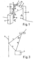
- FIG. 1 an optical door sensor arrangement 1 is shown on a sliding door 2 with an optical sensor 1a above the sliding door 2. Wings 3, 4 of the sliding door 2 are partially open and are closing at speeds V 1 and V r . An object 5, for example a human, moves towards the sliding door 2 at a speed V 0 .
- the door sensor assembly 1 captures 3D images of your surroundings.
- a built-in computer (not shown) analyzes the images and determines therefrom the position and speed of the sliding door leaves 3, 4 and the object 5.
- FIG. 1 are shown for three pixels from a thus determined image vectors 6, 7 and 10.
- the vectors 6 and 7 are directed to pixels of edges 8, 9 of the respective wings 3, 4 and the vector 10 to a pixel of the object 5.
- the edges 8, 9 of the wings 3, 4 and also the object 5 are detected simultaneously over several pixels.
- the inventive approach is explained by the three selected vectors to the corresponding pixel.
- the positions of the pixels can be determined via the vectors 6, 7 and 10.
- an object distance 11, 12 that is in the present case a distance between each of the front edge 8, 9 of the sliding door leaves 4, 5 and the object 5, the angle between the vectors 6 and 10 can be determined. With the amounts of the vectors 6 and 10 then the distance 11, 12 between the object 5 and the respective wing edge 8, 9 can be calculated.
- the relative speed of the object 5 to the two door leaf edges 8, 9 can be determined from a plurality of such measurements. This makes it possible to foresee if the object would collide with one of the two door leaf edges 8, 9. Thus, the door leaves 3, 4, possibly separately, be stopped to avoid a collision. In this process can also be considered the braking distance of the door 3, 4. In conventional door controls with a light curtain or light curtain, however, only the presence of an object can be detected.
- FIG. 2a the object 5 moving in the direction of the sliding door 2 is shown.
- the door sensor arrangement 1 detects the distance 10a to the object 5 and the distances 6a, 7a to the door leaf edges 8, 9. From these distances 6a, 7a, the distances 11, 12 from the object 5 to the door edges can be considered taking into account the angle between the distances 6a and calculate 10a, 7a and 10a, respectively.
- the distances 11, 12 are transmitted to a door control, whereby the movement and position of the door leaves 3, 4 can be controlled as a function of the distances 11, 12.
- FIG. 2b the situation is shown in which the door leaf 3 is partially closed, for example so that less warm air (symbolized by the arrows W) can escape from a room which is entered through the door 2. Not only the current position of the object 5 is considered, but also its speed and the speed of the door wings 3, 4.
- the controller can be adjusted so that the door is decisive, which would cause the fastest collision with the object 5.
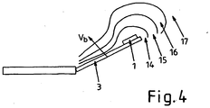
- FIG. 4 is a wing door 3 with symbolized speed ranges 14, 15, 16, 17 shown.
- the door sensor assembly 1 monitors areas 14, 15, 16, 17. If someone is within the range, the gullwing door 3 is stopped. If an object is within the range 15, the process continues in a slower manner. If an object is within the area 16, the process continues comparatively faster and within the area 17 the door is moved at normal speed.
Landscapes
- Power-Operated Mechanisms For Wings (AREA)
Description
- Die Erfindung betrifft eine Vorrichtung zur Steuerung eines angetriebenen Bewegungselements, zum Beispiel einer Tür oder eines Fensters nach dem Oberbegriff des Anspruchs 1.
- Bei bekannten Ausführungsformen wird das Schließen von Schiebetüren mit Sensoren überwacht, mit welchen ein Objekt in der Bewegungsbahn eines Türflügels detektierbar ist, das heißt der Sensor stellt,fest, ob ein Objekt vorhanden ist oder nicht. Eine weitere Differenzierung erfolgt nicht.
- Dementsprechend wird bei der Detektion eines Objektes die Schiebetür immer komplett geöffnet. Im Winter ergibt sich allerdings die Problematik, eine Schiebetür, wenn möglich, geschlossen zu halten, um Wärmeverluste von Räumen, die über die Schiebetür betreten werden können, zu vermeiden.
- Eine bekannte Lösung, um in solchen Situationen weniger Wärme zu verlieren, besteht darin, die Tür nicht ganz zu öffnen. Da Menschen erwarten, dass sich die Tür komplett öffnet, kommt es regelmäßig zur Kollision zwischen Menschen und der nicht ganz geöffneten Tür.
- Aus dem Stand der Technik zeigt die
EP 0 696 670 A1 eine Anordnung zum automatischen Öffnen und Schließen von Türen, bei welcher außerhalb einer Türaktivierungszone eine Überwachungszone definiert ist, in welcher sich Objekte der Tür nähern können. Die Tür wird so betätigt, dass sie zur vorhergesagten Ankunftszeit des Objekts voll geöffnet ist. DieJP 08285184 A US 2002/118,114 A1 beschreibt einen Sensor für automatische Türen, bei welchem mittels Kameras Bilder von den beiden die Tür innen und außen umgebenden Bereichen erstellt werden. Mittels einer Abstandsmesseinheit werden Abstände von auf den Bildern erkannten Objekten in jedem einzelnen Bild ermittelt. Mittels weiterer Boden- und Höhenmesssensoren erfolgt eine weitere Prüfung, ob sich im zu überwachenden Bereich vor bzw. hinter der Tür ein vom Boden bzw. von der Tür verschiedenes Objekt befindet. Sofern dies der Fall ist, wird die Tür vollständig geöffnet bzw. in vollständig geöffnetem Zustand gehalten. DieUS 2004/200,149 A1 beschreibt eine Tür-Raum-Überwachungsvorrichtung zur Überwachung eines Türschrankbereichs einer Kraftfahrzeugtür. Diese ist mit den Türschrankbereich erfassenden Sensormitteln, mit einer Sensordaten auswertenden Auswerteeinrichtung und mit einer Steuereinheit zur Steuerung von Sensormitteln oder von Auswerteeinrichtungen versehen, wobei mittels einer Lichtquelle, einer Mikro-Spiegeleinheit und einem Fotoempfänger ein flächiger Überwachungsbereich überwacht wird. - Der Erfindung liegt die Aufgabe zugrunde, die Steuerung eines angetriebenen Bewegungselements über einen Objektsensor im Hinblick auf das Öffnungs- und/oder Schließverhalten zu verbessern.
- Diese Aufgabe wird durch die Merkmale des Anspruchs 1 gelöst.
- In den abhängigen Ansprüchen sind vorteilhafte und zweckmäßige Weiterbildungen der Erfindung angegeben.
- Die Erfindung geht von einer Vorrichtung zur Steuerung eines angetriebenen Bewegungselements, zum Beispiel einer Tür aus, die eine Elektronikeinheit mit einem Objektsensor umfasst. Der Kern der Erfindung liegt darin, dass die Elektronikeinheit mittels des Objektsensors dazu ausgelegt ist, eine Objekt-Distanz zwischen dem angetriebenen Bewegungselement und einem Objekt im Bereich des Bewegungselements zu ermitteln und abhängig davon die Bewegung des Bewegungselements zu steuern. Durch diese Maßnahme kann zum Beispiel eine Schiebetür immer nur genau so geöffnet werden, dass ein herannahendes und die Tür passierendes Objekt, zum Beispiel eine Person kollisionsfrei die Schiebetür passieren kann. Dementsprechend lassen sich zum Beispiel im Winter die Öffnungszustände und der Grad der Öffnung der Schiebetür auf ein Minimum reduzieren, wodurch unnötige Wärmeverluste aus Räumen, die durch die Schiebetür betreten werden, weitgehend vermeiden können. Der Objektsensor kann z.B. ein optischer Sensor, ein Sensor für andere elektromagnetische Wellen, z.B. Radarwellen und/oder ein Sensor für Schallwellen, z.B. Ultraschallwellen sein.
- In einer besonders bevorzugten Ausgestaltung der Erfindung sind Mittel vorgesehen, die die Objekt-Distanz aus einer Distanz des Objektsensors zum Objekt, einer Distanz vom Objektsensor zum Bewegungselement und dem Winkel zwischen den Distanzrichtungen ermitteln.
- Die Objekt-Distanz wird auf diese Weise indirekt auf der Grundlage von zwei Distanzen inklusive des Winkels zwischen den Distanzen bestimmt. Dadurch kann mittels z.B. eines zentralen Objektsensors jede Distanz zwischen Bewegungselement und Objekt bestimmt werden, sofern der zentrale Objektsensor Informationen über die Distanz zum Bewegungselement und zum Objekt einschließlich des Winkels zwischen diesen Distanzen liefern kann.
- In einer bevorzugten Ausführungsform ist die Elektronikeinheit dazu ausgelegt, zur Bestimmung der Objekt-Distanz als Bezug am Bewegungselement eine Vorderkante des Bewegungselements heranzuziehen. Bei einer Tür wird vorzugsweise die Distanz zu deren Vorderkante ermittelt. Bei diesem Ansatz geht man davon aus, dass die Vorderkante mit einem Objekt, zum Beispiel einer herannahenden Person als erstes kollidiert und daher die Objekt-Distanz in Bezug auf diese Vorderkante erfasst werden sollte.
- In einer überdies bevorzugten Ausgestaltung der Erfindung umfasst der Objektsensor einen Sender und Empfänger für ein Signal, z.B. für Schall oder elektromagnetische Wellen, insbesondere Licht, wobei die Elektronikeinheit dazu ausgebildet ist, eine Distanz, die ein vom Sender ausgesandtes Signal über eine Reflexionsfläche zum Empfänger zurücklegt, durch eine Auswertung eines Signalverlaufs, z.B. bei Licht einer Phase einer auf das Licht aufmodulierten Schwingung zu ermitteln und mit dieser Art der Distanzmessung die Objekt-Distanz zu bestimmen. Grundsätzlich kann als Signal auch ein gepulstes Signal in Frage kommen, bei welchem z.B. eine Phaseninformation ausgewertet wird. Es ist jedoch prinzipiell auch denkbar eine Laufzeitinformation auszuwerten.
- Durch diese Vorgehensweise lässt sich eine Objekt-Distanz mit vergleichsweise hoher Genauigkeit erfassen. Auch die Objekt-Distanz zu mehreren Objekten ist ermittelbar. Durch mehrere Messungen ist es überdies möglich, den zeitlichen Verlauf der Objekt-Distanz, also die Geschwindigkeit zu berechnen, so dass die Objektgeschwindigkeit in die Steuerung des angetriebenen Bewegungselements, zum Beispiel einer Tür miteinbezogen werden kann.
- Neben der Objekt-Geschwindigkeit ist auf diese Weise auch die Geschwindigkeit des angetriebenen Bewegungselements ermittelbar, die für eine optimale Steuerung des angetriebenen Bewegungselements in gleicher Weise wichtig ist.
- In einer überdies bevorzugten Ausgestaltung der Erfindung führt die Elektronikeinheit die Steuerung des angetriebenen Bewegungselements derart aus, dass die Distanz zwischen einer Stelle des angetriebenen Bewegungselements, vorzugsweise der Vorderkante des angetriebenen Bewegungselements und dem Objekt zumindest annähernd auf einem vorgegebenen Wert gehalten wird. Vorzugsweise wird die Objekt-Distanz zumindest abschnittsweise auf einem vorgegebenen Wert gehalten. In einer bevorzugten Ausgestaltung ist es günstig, die Objekt-Distanz kontinuierlich z.B. mehrfach pro Sekunde zu bestimmen. In einer außerdem bevorzugten Ausgestaltung wird die Objekt-Distanz auf einem vorgebbaren konstanten Wert gehalten. Durch das Konstanthalten wird vermieden, dass eine Kollision zwischen Objekt und Bewegungselement eintritt. Es ist jedoch auch möglich, dass der vorgebbare Wert einer Funktion folgt. Denkbar wäre eine Veränderung der vorgegebenen Distanz in Abhängigkeit des Abstandes des Objekts vom angetriebenen Element oder einer Türebene. Die vorgegebene Distanz kann auch davon abhängig gemacht werden, ob die Person sich noch vor der Tür, im Durchgang der Tür oder nach der Tür befindet. Bei der Funktion kann es sich auch um eine diskrete Funktion handeln. Möglich ist auch, dass Parameterfelder vorgegeben werden, z.B. ein Look-uptable. Für den Fall, dass der vorgebbare Wert einen Minimalwert darstellt, ist dieser vorzugsweise abhängig vom Bremsweg des angetriebenen Bewegungselements und/oder von empirisch ermittelten "Wohlfühlparametern", das heißt Werten, bei welcher eine Person mit einem angenehmen Gefühl das angetriebene Bewegungselement passiert. Vorteilhafterweise wird der Minimalwert größer als 10 cm betragen.
- Bei mehreren Bewegungselementen ist es bevorzugt, wenn alle Bewegungselemente unabhängig steuerbar sind. Dadurch lassen sich für die einzelnen Bewegungselemente bestmögliche Bewegungsabläufe erzielen.
- Für den Fall, dass mehrere angetriebene nicht unabhängig bewegbare Bewegungselemente vorgesehen sind, ist es vorteilhaft, wenn die kleinste ermittelte Distanz zu einem Bewegungselement, insbesondere zur Vorderkante eines Bewegungselements für die Steuerung der Bewegungselemente maßgebend ist.
- Durch diese Vorgehensweise kann bei im Wesentlichen nicht erhöhtem Steueraufwand zumindest eine teiloptimierte Bewegung der Bewegungselemente erreicht werden.
- Die Erfindung lässt sich insbesondere auf Schiebetüren, Flügeltüren, vertikale Türen, Falttüren und auch Fenster anwenden.
- Eine weitere Verbesserung der Steuerung der Bewegung des angetriebenen Bewegungselements kann dadurch erzielt werden, dass in einer vorteilhaften Ausgestaltung der Erfindung die Elektronikeinheit ein Steuersignal für die Steuerung des angetriebenen Bewegungselements erzeugt, in welchem ein Bremsweg des angetriebenen Bewegungselements berücksichtigt ist. Dadurch kann die Objekt-Distanz im Hinblick auf deren Minimum noch weiter optimiert werden, was positiv bei der Erniedrigung von Öffnungszuständen, beispielsweise einer Schiebetür genutzt werden kann.
- Um eine noch weiter verfeinerte Steuerung des angetriebenen Bewegungselements hinsichtlich Öffnungs- und/oder Schließzustände des Bewegungselements zu erhalten, wird im Weiteren vorgeschlagen, dass die Elektronikeinheit das angetriebene Bewegungselement so steuert, dass das Bewegungselement, zum Beispiel eine Tür möglichst schnell geschlossen wird, nachdem ein Objekt, zum Beispiel eine Person das Bewegungselement passiert hat und/oder dass das Bewegungselement, zum Beispiel eine Tür, so spät wie möglich geöffnet wird, wenn ein Objekt, zum Beispiel eine Person sich auf das Bewegungselement zu bewegt.
- In einer überdies bevorzugten Ausgestaltung der Erfindung steuert die Elektronikeinheit die Geschwindigkeit des Bewegungselementes auf einen an sich ungestörten Bewegungsweg abhängig von der Objektdistanz. Durch diese Maßnahme kann z.B. bei vergleichsweise großen Objektdistanzen eine erhöhte Geschwindigkeit vorgegeben werden, wobei die Geschwindigkeit bei einer entsprechenden Annäherung an das Objekt sukzessive herabgesetzt wird. Die Geschwindigkeitsanpassung kann z.B. schrittweise erfolgen.
- Im Weiteren ist es bevorzugt, wenn die Elektronikeinheit die Steuerung derart vornimmt, dass wenn das Bewegungselement länger als eine vorgegebene Zeit blockiert wird, dieses mit sanftem Druck den Schließvorgang beendet.
- In den Zeichnungen werden verschiedene Ausführungsbeispiele der Erfindung gezeigt und nachstehend unter Angabe weiterer Vorteile und Einzelheiten näher erläutert. Es zeigen
- Figur 1
- in einer schematischen dreidimensionalen Ansicht eine optische Türsensoranordnung einer zweiflügligen Schiebetür mit herannahendem Objekt,
- Figur 2a-c
- Bewegungszustände der zweiflügligen Schiebetür nach
Figur 1 beim Durchtritt eines Objekts in Draufsicht und - Figur 3
- eine schematische Abbildung, die das Verfahren einer Bestimmung des Abstandes zwischen einer Schiebetürkante und einem Objekt veranschaulicht und
- Figur 4
- eine schematische Draufsicht auf eine Flügeltüre zur Veranschaulichung der Geschwindigkeitssteuerung der Flügeltür.
- In
Figur 1 ist eine optische Türsensoranordnung 1 an einer Schiebetür 2 mit einem optischen Sensor 1a oberhalb der Schiebetür 2 dargestellt. Flügel 3, 4 der Schiebetür 2 sind teilweise geöffnet und schließen sich gerade mit Geschwindigkeiten V1 und Vr. Ein Objekt 5, zum Beispiel ein Mensch bewegt sich mit einer Geschwindigkeit V0 auf die Schiebetür 2 zu. - Die Türsensoranordnung 1 erfasst 3D-Bilder von Ihrer Umgebung. Ein eingebauter Rechner (nicht dargestellt) analysiert die Bilder und ermittelt daraus die Position und Geschwindigkeit der Schiebetürflügel 3, 4 und des Objekts 5. In
Figur 1 sind für drei Pixel aus einem auf diese Weise ermittelten Bild Vektoren 6, 7 und 10 dargestellt. Die Vektoren 6 und 7 sind auf Pixel von Kanten 8, 9 der jeweiligen Flügel 3, 4 und der Vektor 10 auf ein Pixel des Objekts 5 gerichtet. Normalerweise werden die Kanten 8, 9 der Flügel 3, 4 und auch das Objekt 5 über mehrere Pixel gleichzeitig erfasst. Dadurch lässt sich eine höhere Genauigkeit und damit Sicherheit erzielen. Die erfinderische Vorgehensweise wird aber anhand der drei ausgewählten Vektoren zu dem entsprechenden Pixel erklärt. - Die Positionen der Pixel lassen sich über die Vektoren 6, 7 und 10 bestimmen. Für die Bestimmung einer Objekt-Distanz 11, 12 (siehe
Figur 3 ), das heißt im vorliegenden Fall einer Distanz zwischen jeweils der Vorderkante 8, 9 der Schiebetürflügel 4, 5 und dem Objekt 5, lässt sich der Winkel zwischen den Vektoren 6 und 10 ermitteln. Mit den Beträgen der Vektoren 6 und 10 ist dann die Distanz 11, 12 zwischen dem Objekt 5 und der jeweiligen Flügelkante 8, 9 berechenbar. - Aus mehreren solchen Messungen kann zudem die relative Geschwindigkeit vom Objekt 5 zu den beiden Türflügelkanten 8, 9 ermittelt werden. Dies ermöglicht es, vorauszusehen, wenn das Objekt mit einer der beiden Türflügelkanten 8, 9 kollidieren würde. Damit können die Türflügel 3, 4, möglicherweise separat, gestoppt werden, um eine Kollision zu vermeiden. Bei diesem Vorgang lässt sich zudem der Bremsweg der Türflügel 3, 4 berücksichtigen. Bei herkömmlichen Türsteuerungen mit einem Lichtgitter oder Lichtvorhang kann dagegen nur die Anwesenheit eines Objektes festgestellt werden.
- In
Figur 2a wird das Objekt 5, das sich in die Richtung Schiebetür 2 bewegt, gezeigt. Die Türsensoranordnung 1 erfasst die Distanz 10a zum Objekt 5 und die Distanzen 6a, 7a zu den Türflügelkanten 8, 9. Aus diesen Distanzen 6a, 7a lassen sich die Distanzen 11, 12 vom Objekt 5 zu den Türkanten unter Berücksichtigung des Winkels zwischen den Distanzen 6a und 10a bzw. 7a und 10a berechnen. Die Distanzen 11, 12 werden einer Türsteuerung übermittelt, womit die Bewegung und Position der Türflügel 3, 4 in Abhängigkeit der Distanzen 11, 12 gesteuert werden kann. - In
Figur 2b wird die Situation gezeigt, in welcher der Türflügel 3 teilweise geschlossen wird, zum Beispiel damit weniger warme Luft (symbolisiert durch die Pfeile W) aus einem Raum, der durch die Tür 2 betreten wird, entweichen kann. Dabei wird nicht nur die aktuelle Position des Objekts 5 berücksichtigt, sondern auch dessen Geschwindigkeit und die Geschwindigkeit der Türflügel 3, 4. - Für den Fall, dass die Türflügel 3, 4 nicht separat bewegt werden können, lässt sich die Steuerung so einstellen, dass der Türflügel maßgebend ist, der am schnellsten eine Kollision mit dem Objekt 5 verursachen würde.
- Hat das Objekt, so wie in
Figur 2c gezeigt, die Tür 2 passiert, kann auch der Türflügel 4 geschlossen werden. - In
Figur 4 ist eine Flügeltüre 3 mit symbolisierten Geschwindigkeitsbereichen 14, 15, 16, 17 dargestellt. Wenn sich die Flügeltür 3 mit einer Geschwindigkeit Vb öffnet, überwacht die Türsensoranordnung 1 Bereiche 14, 15, 16, 17. Befindet sich jemand innerhalb des Bereichs, so wird die Flügeltür 3 angehalten. Befindet sich ein Objekt innerhalb des Bereichs 15, so wird verlangsamt weitergefahren. Befindet sich ein Objekt innerhalb des Bereichs 16, so wird vergleichsweise schneller weitergefahren und innerhalb des Bereichs 17 wird die Tür mit normaler Geschwindigkeit bewegt.
Claims (9)
- Vorrichtung zur Steuerung eines angetriebenen Bewegungselements (3, 4) in Form einer Tür oder eines Fensters, die eine Elektronikeinheit mit einem Objektsensor (1a) umfasst, wobei die Elektronikeinheit mittels des Objektsensors (1a) dazu ausgelegt ist, eine Objekt-Distanz (11) zwischen dem angetriebenen Bewegungselement (3, 4) und einem Objekt (5) im Bereich des Bewegungselements (3, 4) zu ermitteln und abhängig davon die Bewegung des Bewegungselements (3, 4) zu steuern, wobei das Bewegungselement eine Öffnung schließt und öffnet,
dadurch gekennzeichnet, dass
die Elektronikeinheit weiter ausgebildet ist, zur Bestimmung der Objekt-Distanz (11) als Bezug am Bewegungselement eine Vorderkante (8, 9) des Bewegungselements (3, 4) heranzuziehen, wobei die Vorderkante die Kante ist, an der als erstes eine Kollision zwischen Objekt und Bewegungselement stattfindet und die an der Öffnung liegt und Mittel vorgesehen sind, die Objekt-Distanz (11) aus einer Distanz (10a) des Objektsensors (1a) zum Objekt (5), einer Distanz (6a, 7a) vom Objektsensor (1a) zur Vorderkante des Bewegungselementes (3, 4) und dem Winkel α zwischen den Vektoren (6, 7 und 10) der Distanzrichtungen zu ermitteln. - Vorrichtung nach Anspruch 1, dadurch gekennzeichnet, dass der Objektsensor (1a) einen Sender und Empfänger für ein Signal, z.B. für Schall oder elektromagnetische Wellen, insbesondere Licht umfasst, wobei die Elektronikeinheit dazu ausgebildet ist, eine Distanz, die ein vom Sender ausgesandtes Signal über eine Reflexionsfläche zum Empfänger zurücklegt, durch eine Auswertung eines Signalverlaufs, z.B. bei Licht, einer Phase einer auf das Licht aufmodulierten Schwingung zu ermitteln und mit dieser Art der Distanzmessung die Objekt-Distanz (11) zu bestimmen.
- Vorrichtung nach einem der vorhergehenden Ansprüche, dadurch gekennzeichnet, dass die Elektronikeinheit ein Steuersignal für die Steuerung des angetriebenen Bewegungselements (3, 4) in Abhängigkeit der Geschwindigkeit (V0) des Objekts (5) und/oder der Geschwindigkeit (V1, Vr) des angetriebenen Bewegungselements (3, 4) erzeugt.
- Vorrichtung nach einem der vorhergehenden Ansprüche, dadurch gekennzeichnet, dass die Elektronikeinheit die Steuerung des angetriebenen Bewegungselements (3, 4) derart vornimmt, dass die Objekt-Distanz (11) zwischen einer Stelle des angetriebenen Bewegungselements, vorzugsweise der Vorderkante (8, 9) des angetriebenen Bewegungselements (3, 4) und dem Objekt (5) auf einem vorgegebenen Wert gehalten wird.
- Vorrichtung nach einem der vorhergehenden Ansprüche, dadurch gekennzeichnet, dass mehrere angetriebene Bewegungselemente (3, 4) unabhängig steuerbar sind.
- Vorrichtung nach einem der vorhergehenden Ansprüche, dadurch gekennzeichnet, dass bei mehreren angetriebenen nicht unabhängig bewegbaren Bewegungselementen (3, 4) die kleinste ermittelte Distanz für die Steuerung der Bewegungselemente (3, 4) maßgebend ist.
- Vorrichtung nach einem der vorhergehenden Ansprüche, dadurch gekennzeichnet, dass die Elektronikeinheit ein Steuersignal für die Steuerung des angetriebenen Bewegungselements (3, 4) erzeugt, in welchem ein Bremsweg des angetriebenen Bewegungselements (3, 4) berücksichtigt ist.
- Vorrichtung nach einem der vorhergehenden Ansprüche, dadurch gekennzeichnet, dass die Elektronikeinheit das angetriebene Bewegungselement (3, 4) derart steuert, dass das Bewegungselement (3, 4) möglichst schnell geschlossen wird, nachdem ein Objekt (5) das Bewegungselement (3, 4) passiert hat und/oder dass das Bewegungselement (3, 4) so spät wie möglich geöffnet wird, wenn sich ein Objekt (5) auf das Bewegungselement (3, 4) zu bewegt.
- Vorrichtung nach einem der vorhergehenden Ansprüche, dadurch gekennzeichnet, dass die Elektronikeinheit die Geschwindigkeit des Bewegungselements auf einen an sich ungestörten Bewegungsweg abhängig von der Objekt-Distanz steuert.
Applications Claiming Priority (3)
| Application Number | Priority Date | Filing Date | Title |
|---|---|---|---|
| DE102005018231 | 2005-04-19 | ||
| DE102005023774 | 2005-05-19 | ||
| PCT/EP2006/003577 WO2006111365A1 (de) | 2005-04-19 | 2006-04-19 | Vorrichtung zur steuerung eines angetriebenen bewegungselements, zum beispiel einer tür |
Publications (3)
| Publication Number | Publication Date |
|---|---|
| EP1875030A1 EP1875030A1 (de) | 2008-01-09 |
| EP1875030B1 EP1875030B1 (de) | 2016-07-13 |
| EP1875030B2 true EP1875030B2 (de) | 2019-09-04 |
Family
ID=36694312
Family Applications (1)
| Application Number | Title | Priority Date | Filing Date |
|---|---|---|---|
| EP06742608.0A Expired - Lifetime EP1875030B2 (de) | 2005-04-19 | 2006-04-19 | Vorrichtung zur steuerung eines angetriebenen bewegungselements, zum beispiel einer tür |
Country Status (5)
| Country | Link |
|---|---|
| US (1) | US9145727B2 (de) |
| EP (1) | EP1875030B2 (de) |
| JP (1) | JP2008537040A (de) |
| CN (1) | CN101180444B (de) |
| WO (1) | WO2006111365A1 (de) |
Families Citing this family (23)
| Publication number | Priority date | Publication date | Assignee | Title |
|---|---|---|---|---|
| DE102007050334A1 (de) * | 2007-10-18 | 2009-04-23 | Efaflex Tor- Und Sicherheitssysteme Gmbh & Co. Kg | Verfahren und Einrichtung zur Steuerung eines vertikal oder horizontal bewegten Tores unter Absicherung der Torschließebene gegenüber Hindernissen |
| DE102007060343A1 (de) * | 2007-12-14 | 2009-06-18 | Hörmann Kg Dissen | Überwachungsvorrichtung für ein angetriebenes Tor und damit ausgestattetes Tor |
| DK2506034T3 (da) | 2011-04-01 | 2013-09-02 | Cedes Ag | Sensorindretning, sikkerhedsindretning, dør og fremgangsmåde til kontrol af bevægelsen |
| DE102012106889A1 (de) * | 2012-07-30 | 2014-01-30 | Fraba N.V. | Überwachungs- und Ansteuervorrichtung für eine Toreinheit |
| US9623015B2 (en) | 2012-11-05 | 2017-04-18 | Commissariat À L'energie Atomique Et Aux Energies Alternatives (Cea) | Combination of an anti-cancer agent such as a tyrosinekinase inhibitor and a STAT5 antagonist, preferably a thiazolidinedione, for eliminating hematologic cancer stem cells in vivo and for preventing hematologic cancer relapse |
| US9804576B2 (en) | 2013-02-27 | 2017-10-31 | Rockwell Automation Technologies, Inc. | Recognition-based industrial automation control with position and derivative decision reference |
| US9798302B2 (en) | 2013-02-27 | 2017-10-24 | Rockwell Automation Technologies, Inc. | Recognition-based industrial automation control with redundant system input support |
| US9498885B2 (en) | 2013-02-27 | 2016-11-22 | Rockwell Automation Technologies, Inc. | Recognition-based industrial automation control with confidence-based decision support |
| US9393695B2 (en) | 2013-02-27 | 2016-07-19 | Rockwell Automation Technologies, Inc. | Recognition-based industrial automation control with person and object discrimination |
| JP6316644B2 (ja) * | 2014-04-23 | 2018-04-25 | ファナック株式会社 | 扉の速度を制御可能なシステム |
| JP2014238005A (ja) * | 2014-08-21 | 2014-12-18 | 寺岡ファシリティーズ株式会社 | 自動ドアシステム |
| DE102015101017B4 (de) * | 2015-01-23 | 2018-02-22 | Efaflex Tor- Und Sicherheitssysteme Gmbh & Co. Kg | Verfahren zur Steuerung einer Toranordnung sowie derartige Toranordnung und eine Sicherheitseinrichtung hierfür |
| DE102015103756A1 (de) | 2015-03-13 | 2016-09-15 | Gu Automatic Gmbh | Automatiktür, wie beispielsweise eine Schiebetür, eine Drehtür oder dergleichen |
| JP6321708B2 (ja) * | 2016-03-17 | 2018-05-09 | ファナック株式会社 | 工作機械システムおよび開停止位置算出装置 |
| GB2549760B (en) * | 2016-04-28 | 2018-04-25 | Ensota Guangzhou Tech Ltd | An automatic door installation |
| JP7012488B2 (ja) * | 2017-09-11 | 2022-01-28 | 株式会社日立製作所 | エレベーターのドア制御装置ならびにエレベーターのドア駆動システム |
| US11066276B2 (en) * | 2018-04-30 | 2021-07-20 | Otis Elevator Company | Enhanced door detection |
| JP7248216B2 (ja) * | 2019-07-03 | 2023-03-29 | 三井金属アクト株式会社 | ドア開閉制御システム |
| CN110863733A (zh) * | 2019-12-09 | 2020-03-06 | 长沙莫之比智能科技有限公司 | 一种轨迹触发的毫米波雷达自动门控制策略及系统 |
| JP7393995B2 (ja) * | 2020-03-30 | 2023-12-07 | 文化シヤッター株式会社 | 開閉装置、制御プログラム、及び開閉部材の制御方法 |
| CN112360285B (zh) * | 2020-10-27 | 2023-07-11 | 浙江清华长三角研究院 | 自动门立体机器视觉传感器及其传感方法 |
| SE546983C2 (en) * | 2023-02-13 | 2025-03-25 | Assa Abloy Ab | Controlling a sliding door comprising a first door leaf and a second door leaf |
| WO2025012435A1 (en) * | 2023-07-13 | 2025-01-16 | Assa Abloy Entrance Systems Ab | System and method for operating an automatic door system using a radar sensor |
Citations (3)
| Publication number | Priority date | Publication date | Assignee | Title |
|---|---|---|---|---|
| EP0799962A1 (de) † | 1996-04-02 | 1997-10-08 | Heinrich Landert | Verfahren zum Betrieb einer Türanlage und eine nach dem Verfahren arbeitende Türanlage |
| EP0935044A2 (de) † | 1998-02-05 | 1999-08-11 | agta record ag | Verfahren und Vorrichtung zur Ansteuerung und/oder Überwachung eines motorisch angetriebenen Flügels |
| EP1345444A1 (de) † | 2002-03-11 | 2003-09-17 | Inventio Ag | Video Überwachungssystem mittels 3-D Halbleiterbildsensor und Infra-Rot Lichtquelle |
Family Cites Families (34)
| Publication number | Priority date | Publication date | Assignee | Title |
|---|---|---|---|---|
| US4029176A (en) * | 1975-10-06 | 1977-06-14 | Mills Gerald W | Doorway safety device |
| USRE30719E (en) * | 1978-08-02 | 1981-08-25 | Doorway safety device | |
| SE459997B (sv) * | 1984-09-26 | 1989-08-28 | Besam Ab | Anordning foer styrning av oeppning och staengning av doerrar, luckor och dylikt |
| US4815046A (en) * | 1985-04-29 | 1989-03-21 | Xecutek Corporation | Ultrasonic sensor system |
| ES2041850T3 (es) * | 1988-06-03 | 1993-12-01 | Inventio Ag | Procedimiento y dispositivo para el control de la posicion de una puerta automatica. |
| US4967083A (en) * | 1989-04-14 | 1990-10-30 | The Stanley Works | Door sensor system |
| JPH07119543B2 (ja) * | 1990-03-22 | 1995-12-20 | 株式会社ナブコ | 扉開閉制御装置 |
| GB2254916B (en) * | 1991-04-15 | 1993-12-22 | John Trett | Detection systems |
| JP2919284B2 (ja) * | 1994-02-23 | 1999-07-12 | 松下電工株式会社 | 物体認識方法 |
| US5583405A (en) * | 1994-08-11 | 1996-12-10 | Nabco Limited | Automatic door opening and closing system |
| US5541585A (en) * | 1994-10-11 | 1996-07-30 | Stanley Home Automation | Security system for controlling building access |
| JPH08285184A (ja) * | 1995-04-19 | 1996-11-01 | Toshiba Corp | 扉開度制限装置 |
| JPH09209652A (ja) * | 1996-01-31 | 1997-08-12 | Nabco Ltd | スイングドア用センサ |
| JP3352911B2 (ja) * | 1996-05-17 | 2002-12-03 | 株式会社ナブコ | 自動ドア装置の自己診断装置 |
| US5627439A (en) * | 1996-07-08 | 1997-05-06 | Inventio Ag | Light barrier for reopening elevator doors |
| US6304178B1 (en) * | 1997-01-20 | 2001-10-16 | Kabushiki Kaisha Tsuden | Door safety system |
| US6329774B1 (en) * | 1998-02-08 | 2001-12-11 | Janus Development Ltd. | Ultrasonic method and apparatus for automatically controlling moving doors |
| JP2000073657A (ja) * | 1998-09-01 | 2000-03-07 | Mitsubishi Electric Corp | 自動ドアシステム |
| US20020178321A1 (en) * | 1998-11-25 | 2002-11-28 | Philip J. Calamatas | Programmable system including self locking memory circuit for a tristate data bus |
| US7042492B2 (en) | 1999-12-10 | 2006-05-09 | The Stanley Works | Automatic door assembly with video imaging device |
| US6678999B2 (en) | 2000-09-28 | 2004-01-20 | Nabco Limited | Object sensing system for use with automatic swing door |
| JP4639293B2 (ja) | 2001-02-27 | 2011-02-23 | オプテックス株式会社 | 自動ドアセンサ |
| JP4771245B2 (ja) * | 2001-04-27 | 2011-09-14 | オプテックス株式会社 | 自動ドアセンサ |
| JP3855234B2 (ja) * | 2002-07-09 | 2006-12-06 | オプテックス株式会社 | ドアセンサ及びそのドアセンサを備えたドア |
| US7400744B2 (en) * | 2002-09-05 | 2008-07-15 | Cognex Technology And Investment Corporation | Stereo door sensor |
| US7045764B2 (en) * | 2002-10-17 | 2006-05-16 | Rite-Hite Holding Corporation | Passive detection system for detecting a body near a door |
| EP1467057A2 (de) | 2003-04-11 | 2004-10-13 | DaimlerChrysler AG | Türraumüberwachungsvorrichtung zur Überwachung eines Türschwenkbereiches einer Kraftfahrzeugtüre |
| EP1484467A3 (de) | 2003-06-04 | 2008-10-08 | DORMA GmbH + Co. KG | Türsteuerung mit einem Präsenzsensor |
| JP4267996B2 (ja) | 2003-09-17 | 2009-05-27 | Thk株式会社 | 自動扉装置 |
| US7623674B2 (en) * | 2003-11-05 | 2009-11-24 | Cognex Technology And Investment Corporation | Method and system for enhanced portal security through stereoscopy |
| US7332999B2 (en) * | 2004-04-19 | 2008-02-19 | The Chamberlain Group, Inc. | System and method for operating multiple moveable barrier operators |
| JP4736017B2 (ja) * | 2004-10-22 | 2011-07-27 | オプテックス株式会社 | スイングドア開閉検知システム |
| US7762022B2 (en) * | 2005-07-08 | 2010-07-27 | Bea, Inc. | Automatic door opening and closing system and method of control thereof |
| US7719213B2 (en) * | 2006-10-19 | 2010-05-18 | Herman Stephen A | Door actuator and opener |
-
2006
- 2006-04-19 CN CN2006800172656A patent/CN101180444B/zh not_active Expired - Lifetime
- 2006-04-19 EP EP06742608.0A patent/EP1875030B2/de not_active Expired - Lifetime
- 2006-04-19 WO PCT/EP2006/003577 patent/WO2006111365A1/de not_active Ceased
- 2006-04-19 JP JP2008506998A patent/JP2008537040A/ja active Pending
-
2007
- 2007-10-18 US US11/874,345 patent/US9145727B2/en active Active
Patent Citations (3)
| Publication number | Priority date | Publication date | Assignee | Title |
|---|---|---|---|---|
| EP0799962A1 (de) † | 1996-04-02 | 1997-10-08 | Heinrich Landert | Verfahren zum Betrieb einer Türanlage und eine nach dem Verfahren arbeitende Türanlage |
| EP0935044A2 (de) † | 1998-02-05 | 1999-08-11 | agta record ag | Verfahren und Vorrichtung zur Ansteuerung und/oder Überwachung eines motorisch angetriebenen Flügels |
| EP1345444A1 (de) † | 2002-03-11 | 2003-09-17 | Inventio Ag | Video Überwachungssystem mittels 3-D Halbleiterbildsensor und Infra-Rot Lichtquelle |
Also Published As
| Publication number | Publication date |
|---|---|
| JP2008537040A (ja) | 2008-09-11 |
| US20080084300A1 (en) | 2008-04-10 |
| CN101180444B (zh) | 2013-01-16 |
| CN101180444A (zh) | 2008-05-14 |
| WO2006111365A1 (de) | 2006-10-26 |
| EP1875030A1 (de) | 2008-01-09 |
| US9145727B2 (en) | 2015-09-29 |
| EP1875030B1 (de) | 2016-07-13 |
Similar Documents
| Publication | Publication Date | Title |
|---|---|---|
| EP1875030B1 (de) | Vorrichtung zur steuerung eines angetriebenen bewegungselements, zum beispiel einer tür | |
| EP2506034B1 (de) | Sensorvorrichtung, Sicherheitsvorrichtung, Tor und Verfahren zur Kontrolle der Bewegung | |
| DE602005004571T2 (de) | Objektdetektionssystem für eine motorisch angetriebene Tür und Verfahren | |
| EP3325748B1 (de) | Türkomponente mit einer steuerbaren dämpfereinrichtung | |
| EP4153837B1 (de) | Verfahren und vorrichtung zum betrieb einer automatischen türanlage | |
| DE102007038421B3 (de) | Sicherheitsvorrichtung und Verfahren zum Überwachen einer automatischen Tür | |
| DE102008044990B4 (de) | Verfahren und Vorrichtung zur Ansteuerung und/oder Überwachung eines motorisch angetriebenen Flügels während der Öffnungsphase | |
| DE112007001481T5 (de) | System und Verfahren zum Steuern der Geschwindigkeit eines Schließelements | |
| EP3581747B1 (de) | Überwachungseinrichtung | |
| EP3575534B1 (de) | Vorrichtung zur sensorischen absicherung der flügelbewegungen einer automatischen drehtür | |
| DE19653026B4 (de) | Vorrichtung zur Ansteuerung und/oder Absicherung eines motorisch angetriebenen Flügels einer Tür, eines Fensters oder dergleichen | |
| DE102010014806B4 (de) | Torantriebsvorrichtung, damit versehener Gebäudeabschluss, Torsystem und Herstell- und Antriebsverfahren | |
| EP1375808A2 (de) | Sensorvorrichtung für eine automatische Drehtüranlage | |
| DE102004005688A1 (de) | Einklemmschutzsystem für ein Fensterhebersystem in einem Kraftfahrzeug sowie Verfahren zur Steuerung eines Fensterhebersystems | |
| EP3135846B1 (de) | Antriebssystem mit sensoreinheit zur antriebsregelung | |
| EP2818620B1 (de) | Automatische Fenster- oder Türanlage | |
| EP0935044A2 (de) | Verfahren und Vorrichtung zur Ansteuerung und/oder Überwachung eines motorisch angetriebenen Flügels | |
| DE19804631C2 (de) | Verfahren und Vorrichtung zur Ansteuerung und/oder Überwachung eines motorisch angetriebenen Flügels | |
| DE102006018326A1 (de) | Vorrichtung zur Steuerung eines angetriebenen Bewegungselements, zum Beispiel einer Tür | |
| DE29701462U1 (de) | Vorrichtung zur automatischen Steuerung von Toren oder Türen | |
| DE202013002006U1 (de) | Kontrolleinrichtung | |
| DE102012008086A1 (de) | Verfahren zum Betreiben einer Vorrichtung eines Fahrzeugs | |
| EP3258046B1 (de) | Schliessvorrichtung für eine gebäudeöffnung | |
| EP0852313A1 (de) | Vorrichtung zur Ansteuerung und/oder Absicherung eines motorisch angetriebenen Flügels einer Tür, eines Fensters oder dergleichen | |
| EP0935042A2 (de) | Verfahren und Vorrichtung zur Ansteuerung und/oder Überwachung eines motorisch angetriebenen Flügels |
Legal Events
| Date | Code | Title | Description |
|---|---|---|---|
| PUAI | Public reference made under article 153(3) epc to a published international application that has entered the european phase |
Free format text: ORIGINAL CODE: 0009012 |
|
| 17P | Request for examination filed |
Effective date: 20071119 |
|
| AK | Designated contracting states |
Kind code of ref document: A1 Designated state(s): AT BE BG CH CY CZ DE DK EE ES FI FR GB GR HU IE IS IT LI LT LU LV MC NL PL PT RO SE SI SK TR |
|
| DAX | Request for extension of the european patent (deleted) | ||
| 17Q | First examination report despatched |
Effective date: 20090223 |
|
| REG | Reference to a national code |
Ref country code: DE Ref legal event code: R079 Ref document number: 502006015036 Country of ref document: DE Free format text: PREVIOUS MAIN CLASS: E05F0015200000 Ipc: E05F0015730000 |
|
| RIC1 | Information provided on ipc code assigned before grant |
Ipc: E05F 15/73 20150101AFI20151001BHEP |
|
| GRAP | Despatch of communication of intention to grant a patent |
Free format text: ORIGINAL CODE: EPIDOSNIGR1 |
|
| INTG | Intention to grant announced |
Effective date: 20151112 |
|
| INTG | Intention to grant announced |
Effective date: 20160212 |
|
| GRAS | Grant fee paid |
Free format text: ORIGINAL CODE: EPIDOSNIGR3 |
|
| GRAA | (expected) grant |
Free format text: ORIGINAL CODE: 0009210 |
|
| AK | Designated contracting states |
Kind code of ref document: B1 Designated state(s): AT BE BG CH CY CZ DE DK EE ES FI FR GB GR HU IE IS IT LI LT LU LV MC NL PL PT RO SE SI SK TR |
|
| REG | Reference to a national code |
Ref country code: GB Ref legal event code: FG4D Free format text: NOT ENGLISH |
|
| REG | Reference to a national code |
Ref country code: AT Ref legal event code: REF Ref document number: 812490 Country of ref document: AT Kind code of ref document: T Effective date: 20160715 Ref country code: CH Ref legal event code: EP |
|
| REG | Reference to a national code |
Ref country code: IE Ref legal event code: FG4D Free format text: LANGUAGE OF EP DOCUMENT: GERMAN |
|
| REG | Reference to a national code |
Ref country code: DE Ref legal event code: R096 Ref document number: 502006015036 Country of ref document: DE |
|
| REG | Reference to a national code |
Ref country code: NL Ref legal event code: FP |
|
| REG | Reference to a national code |
Ref country code: LT Ref legal event code: MG4D |
|
| PG25 | Lapsed in a contracting state [announced via postgrant information from national office to epo] |
Ref country code: IS Free format text: LAPSE BECAUSE OF FAILURE TO SUBMIT A TRANSLATION OF THE DESCRIPTION OR TO PAY THE FEE WITHIN THE PRESCRIBED TIME-LIMIT Effective date: 20161113 Ref country code: LT Free format text: LAPSE BECAUSE OF FAILURE TO SUBMIT A TRANSLATION OF THE DESCRIPTION OR TO PAY THE FEE WITHIN THE PRESCRIBED TIME-LIMIT Effective date: 20160713 Ref country code: IT Free format text: LAPSE BECAUSE OF FAILURE TO SUBMIT A TRANSLATION OF THE DESCRIPTION OR TO PAY THE FEE WITHIN THE PRESCRIBED TIME-LIMIT Effective date: 20160713 |
|
| PG25 | Lapsed in a contracting state [announced via postgrant information from national office to epo] |
Ref country code: LV Free format text: LAPSE BECAUSE OF FAILURE TO SUBMIT A TRANSLATION OF THE DESCRIPTION OR TO PAY THE FEE WITHIN THE PRESCRIBED TIME-LIMIT Effective date: 20160713 Ref country code: SE Free format text: LAPSE BECAUSE OF FAILURE TO SUBMIT A TRANSLATION OF THE DESCRIPTION OR TO PAY THE FEE WITHIN THE PRESCRIBED TIME-LIMIT Effective date: 20160713 Ref country code: GR Free format text: LAPSE BECAUSE OF FAILURE TO SUBMIT A TRANSLATION OF THE DESCRIPTION OR TO PAY THE FEE WITHIN THE PRESCRIBED TIME-LIMIT Effective date: 20161014 Ref country code: ES Free format text: LAPSE BECAUSE OF FAILURE TO SUBMIT A TRANSLATION OF THE DESCRIPTION OR TO PAY THE FEE WITHIN THE PRESCRIBED TIME-LIMIT Effective date: 20160713 Ref country code: PL Free format text: LAPSE BECAUSE OF FAILURE TO SUBMIT A TRANSLATION OF THE DESCRIPTION OR TO PAY THE FEE WITHIN THE PRESCRIBED TIME-LIMIT Effective date: 20160713 Ref country code: PT Free format text: LAPSE BECAUSE OF FAILURE TO SUBMIT A TRANSLATION OF THE DESCRIPTION OR TO PAY THE FEE WITHIN THE PRESCRIBED TIME-LIMIT Effective date: 20161114 |
|
| REG | Reference to a national code |
Ref country code: DE Ref legal event code: R026 Ref document number: 502006015036 Country of ref document: DE |
|
| PLBI | Opposition filed |
Free format text: ORIGINAL CODE: 0009260 |
|
| PG25 | Lapsed in a contracting state [announced via postgrant information from national office to epo] |
Ref country code: RO Free format text: LAPSE BECAUSE OF FAILURE TO SUBMIT A TRANSLATION OF THE DESCRIPTION OR TO PAY THE FEE WITHIN THE PRESCRIBED TIME-LIMIT Effective date: 20160713 Ref country code: EE Free format text: LAPSE BECAUSE OF FAILURE TO SUBMIT A TRANSLATION OF THE DESCRIPTION OR TO PAY THE FEE WITHIN THE PRESCRIBED TIME-LIMIT Effective date: 20160713 |
|
| PLAX | Notice of opposition and request to file observation + time limit sent |
Free format text: ORIGINAL CODE: EPIDOSNOBS2 |
|
| 26 | Opposition filed |
Opponent name: GEZE GMBH Effective date: 20170413 |
|
| PG25 | Lapsed in a contracting state [announced via postgrant information from national office to epo] |
Ref country code: DK Free format text: LAPSE BECAUSE OF FAILURE TO SUBMIT A TRANSLATION OF THE DESCRIPTION OR TO PAY THE FEE WITHIN THE PRESCRIBED TIME-LIMIT Effective date: 20160713 Ref country code: CZ Free format text: LAPSE BECAUSE OF FAILURE TO SUBMIT A TRANSLATION OF THE DESCRIPTION OR TO PAY THE FEE WITHIN THE PRESCRIBED TIME-LIMIT Effective date: 20160713 Ref country code: SK Free format text: LAPSE BECAUSE OF FAILURE TO SUBMIT A TRANSLATION OF THE DESCRIPTION OR TO PAY THE FEE WITHIN THE PRESCRIBED TIME-LIMIT Effective date: 20160713 Ref country code: BG Free format text: LAPSE BECAUSE OF FAILURE TO SUBMIT A TRANSLATION OF THE DESCRIPTION OR TO PAY THE FEE WITHIN THE PRESCRIBED TIME-LIMIT Effective date: 20161013 |
|
| PG25 | Lapsed in a contracting state [announced via postgrant information from national office to epo] |
Ref country code: SI Free format text: LAPSE BECAUSE OF FAILURE TO SUBMIT A TRANSLATION OF THE DESCRIPTION OR TO PAY THE FEE WITHIN THE PRESCRIBED TIME-LIMIT Effective date: 20160713 |
|
| PLBB | Reply of patent proprietor to notice(s) of opposition received |
Free format text: ORIGINAL CODE: EPIDOSNOBS3 |
|
| REG | Reference to a national code |
Ref country code: CH Ref legal event code: PL |
|
| GBPC | Gb: european patent ceased through non-payment of renewal fee |
Effective date: 20170419 |
|
| REG | Reference to a national code |
Ref country code: IE Ref legal event code: MM4A |
|
| REG | Reference to a national code |
Ref country code: FR Ref legal event code: ST Effective date: 20171229 |
|
| PG25 | Lapsed in a contracting state [announced via postgrant information from national office to epo] |
Ref country code: FR Free format text: LAPSE BECAUSE OF NON-PAYMENT OF DUE FEES Effective date: 20170502 Ref country code: MC Free format text: LAPSE BECAUSE OF FAILURE TO SUBMIT A TRANSLATION OF THE DESCRIPTION OR TO PAY THE FEE WITHIN THE PRESCRIBED TIME-LIMIT Effective date: 20160713 |
|
| PG25 | Lapsed in a contracting state [announced via postgrant information from national office to epo] |
Ref country code: GB Free format text: LAPSE BECAUSE OF NON-PAYMENT OF DUE FEES Effective date: 20170419 Ref country code: LU Free format text: LAPSE BECAUSE OF NON-PAYMENT OF DUE FEES Effective date: 20170419 Ref country code: LI Free format text: LAPSE BECAUSE OF NON-PAYMENT OF DUE FEES Effective date: 20170430 Ref country code: CH Free format text: LAPSE BECAUSE OF NON-PAYMENT OF DUE FEES Effective date: 20170430 |
|
| PG25 | Lapsed in a contracting state [announced via postgrant information from national office to epo] |
Ref country code: IE Free format text: LAPSE BECAUSE OF NON-PAYMENT OF DUE FEES Effective date: 20170419 |
|
| REG | Reference to a national code |
Ref country code: AT Ref legal event code: MM01 Ref document number: 812490 Country of ref document: AT Kind code of ref document: T Effective date: 20170419 |
|
| PG25 | Lapsed in a contracting state [announced via postgrant information from national office to epo] |
Ref country code: AT Free format text: LAPSE BECAUSE OF NON-PAYMENT OF DUE FEES Effective date: 20170419 |
|
| PG25 | Lapsed in a contracting state [announced via postgrant information from national office to epo] |
Ref country code: HU Free format text: LAPSE BECAUSE OF FAILURE TO SUBMIT A TRANSLATION OF THE DESCRIPTION OR TO PAY THE FEE WITHIN THE PRESCRIBED TIME-LIMIT; INVALID AB INITIO Effective date: 20060419 |
|
| PUAH | Patent maintained in amended form |
Free format text: ORIGINAL CODE: 0009272 |
|
| STAA | Information on the status of an ep patent application or granted ep patent |
Free format text: STATUS: PATENT MAINTAINED AS AMENDED |
|
| 27A | Patent maintained in amended form |
Effective date: 20190904 |
|
| AK | Designated contracting states |
Kind code of ref document: B2 Designated state(s): AT BE BG CH CY CZ DE DK EE ES FI FR GB GR HU IE IS IT LI LT LU LV MC NL PL PT RO SE SI SK TR |
|
| REG | Reference to a national code |
Ref country code: DE Ref legal event code: R102 Ref document number: 502006015036 Country of ref document: DE |
|
| REG | Reference to a national code |
Ref country code: DE Ref legal event code: R082 Ref document number: 502006015036 Country of ref document: DE Representative=s name: OTTEN, ROTH, DOBLER & PARTNER MBB PATENTANWAEL, DE |
|
| PG25 | Lapsed in a contracting state [announced via postgrant information from national office to epo] |
Ref country code: CY Free format text: LAPSE BECAUSE OF NON-PAYMENT OF DUE FEES Effective date: 20160713 |
|
| REG | Reference to a national code |
Ref country code: NL Ref legal event code: FP |
|
| PG25 | Lapsed in a contracting state [announced via postgrant information from national office to epo] |
Ref country code: TR Free format text: LAPSE BECAUSE OF FAILURE TO SUBMIT A TRANSLATION OF THE DESCRIPTION OR TO PAY THE FEE WITHIN THE PRESCRIBED TIME-LIMIT Effective date: 20160713 |
|
| PGFP | Annual fee paid to national office [announced via postgrant information from national office to epo] |
Ref country code: NL Payment date: 20220419 Year of fee payment: 17 |
|
| PGFP | Annual fee paid to national office [announced via postgrant information from national office to epo] |
Ref country code: FI Payment date: 20220414 Year of fee payment: 17 |
|
| P01 | Opt-out of the competence of the unified patent court (upc) registered |
Effective date: 20230519 |
|
| REG | Reference to a national code |
Ref country code: NL Ref legal event code: MM Effective date: 20230501 |
|
| PG25 | Lapsed in a contracting state [announced via postgrant information from national office to epo] |
Ref country code: NL Free format text: LAPSE BECAUSE OF NON-PAYMENT OF DUE FEES Effective date: 20230501 Ref country code: FI Free format text: LAPSE BECAUSE OF NON-PAYMENT OF DUE FEES Effective date: 20230419 |
|
| REG | Reference to a national code |
Ref country code: DE Ref legal event code: R082 Ref document number: 502006015036 Country of ref document: DE Representative=s name: RAVENSPAT PATENTANWAELTE PARTNERSCHAFT MBB, DE |
|
| PGFP | Annual fee paid to national office [announced via postgrant information from national office to epo] |
Ref country code: DE Payment date: 20250417 Year of fee payment: 20 |
|
| PGFP | Annual fee paid to national office [announced via postgrant information from national office to epo] |
Ref country code: BE Payment date: 20250422 Year of fee payment: 20 |
|
| REG | Reference to a national code |
Ref country code: DE Ref legal event code: R071 Ref document number: 502006015036 Country of ref document: DE |