EP1874696B1 - System und verfahren zur steuerung der umgebung eines oder mehrerer behälter in einem glasherstellungssystem - Google Patents
System und verfahren zur steuerung der umgebung eines oder mehrerer behälter in einem glasherstellungssystem Download PDFInfo
- Publication number
- EP1874696B1 EP1874696B1 EP06750813.5A EP06750813A EP1874696B1 EP 1874696 B1 EP1874696 B1 EP 1874696B1 EP 06750813 A EP06750813 A EP 06750813A EP 1874696 B1 EP1874696 B1 EP 1874696B1
- Authority
- EP
- European Patent Office
- Prior art keywords
- vessel
- glass
- capsule
- atmosphere
- gas mixture
- Prior art date
- Legal status (The legal status is an assumption and is not a legal conclusion. Google has not performed a legal analysis and makes no representation as to the accuracy of the status listed.)
- Ceased
Links
- 239000011521 glass Substances 0.000 title claims description 106
- 238000000034 method Methods 0.000 title claims description 31
- 238000004519 manufacturing process Methods 0.000 title claims description 23
- 239000002775 capsule Substances 0.000 claims description 80
- 239000001257 hydrogen Substances 0.000 claims description 53
- 229910052739 hydrogen Inorganic materials 0.000 claims description 53
- 239000001301 oxygen Substances 0.000 claims description 52
- 229910052760 oxygen Inorganic materials 0.000 claims description 52
- UFHFLCQGNIYNRP-UHFFFAOYSA-N Hydrogen Chemical compound [H][H] UFHFLCQGNIYNRP-UHFFFAOYSA-N 0.000 claims description 49
- QVGXLLKOCUKJST-UHFFFAOYSA-N atomic oxygen Chemical compound [O] QVGXLLKOCUKJST-UHFFFAOYSA-N 0.000 claims description 48
- 239000007789 gas Substances 0.000 claims description 43
- 239000006060 molten glass Substances 0.000 claims description 28
- 238000002844 melting Methods 0.000 claims description 24
- 230000008018 melting Effects 0.000 claims description 24
- 239000000203 mixture Substances 0.000 claims description 22
- 238000007254 oxidation reaction Methods 0.000 claims description 22
- 230000015572 biosynthetic process Effects 0.000 claims description 18
- XLYOFNOQVPJJNP-UHFFFAOYSA-N water Chemical compound O XLYOFNOQVPJJNP-UHFFFAOYSA-N 0.000 claims description 17
- 239000010970 precious metal Substances 0.000 claims description 15
- 238000001816 cooling Methods 0.000 claims description 14
- 230000003647 oxidation Effects 0.000 claims description 11
- QGZKDVFQNNGYKY-UHFFFAOYSA-N Ammonia Chemical compound N QGZKDVFQNNGYKY-UHFFFAOYSA-N 0.000 claims description 6
- 239000011261 inert gas Substances 0.000 claims description 5
- 238000012545 processing Methods 0.000 claims description 4
- 229910021529 ammonia Inorganic materials 0.000 claims description 3
- BASFCYQUMIYNBI-UHFFFAOYSA-N platinum Chemical compound [Pt] BASFCYQUMIYNBI-UHFFFAOYSA-N 0.000 description 48
- 229910052697 platinum Inorganic materials 0.000 description 24
- 229910052751 metal Inorganic materials 0.000 description 17
- 239000002184 metal Substances 0.000 description 17
- 229910001868 water Inorganic materials 0.000 description 14
- IJGRMHOSHXDMSA-UHFFFAOYSA-N Atomic nitrogen Chemical compound N#N IJGRMHOSHXDMSA-UHFFFAOYSA-N 0.000 description 10
- 238000002156 mixing Methods 0.000 description 9
- 239000000156 glass melt Substances 0.000 description 7
- 241000894007 species Species 0.000 description 7
- 239000006025 fining agent Substances 0.000 description 6
- 229910052785 arsenic Inorganic materials 0.000 description 5
- RQNWIZPPADIBDY-UHFFFAOYSA-N arsenic atom Chemical compound [As] RQNWIZPPADIBDY-UHFFFAOYSA-N 0.000 description 5
- 238000000354 decomposition reaction Methods 0.000 description 5
- 238000007499 fusion processing Methods 0.000 description 5
- 229910052757 nitrogen Inorganic materials 0.000 description 5
- -1 oxygen ions Chemical class 0.000 description 5
- 238000012546 transfer Methods 0.000 description 5
- XKRFYHLGVUSROY-UHFFFAOYSA-N Argon Chemical compound [Ar] XKRFYHLGVUSROY-UHFFFAOYSA-N 0.000 description 4
- 230000008901 benefit Effects 0.000 description 4
- 150000002431 hydrogen Chemical class 0.000 description 4
- 239000003870 refractory metal Substances 0.000 description 4
- 238000003756 stirring Methods 0.000 description 4
- MYMOFIZGZYHOMD-UHFFFAOYSA-N Dioxygen Chemical compound O=O MYMOFIZGZYHOMD-UHFFFAOYSA-N 0.000 description 3
- 238000006243 chemical reaction Methods 0.000 description 3
- 229910001882 dioxygen Inorganic materials 0.000 description 3
- 229910052736 halogen Inorganic materials 0.000 description 3
- 150000002367 halogens Chemical class 0.000 description 3
- 239000000463 material Substances 0.000 description 3
- 239000000047 product Substances 0.000 description 3
- 230000009467 reduction Effects 0.000 description 3
- KDLHZDBZIXYQEI-UHFFFAOYSA-N Palladium Chemical compound [Pd] KDLHZDBZIXYQEI-UHFFFAOYSA-N 0.000 description 2
- MCMNRKCIXSYSNV-UHFFFAOYSA-N Zirconium dioxide Chemical compound O=[Zr]=O MCMNRKCIXSYSNV-UHFFFAOYSA-N 0.000 description 2
- 229910052786 argon Inorganic materials 0.000 description 2
- 230000009286 beneficial effect Effects 0.000 description 2
- 230000015556 catabolic process Effects 0.000 description 2
- 230000008859 change Effects 0.000 description 2
- 238000000576 coating method Methods 0.000 description 2
- 230000007423 decrease Effects 0.000 description 2
- 238000003487 electrochemical reaction Methods 0.000 description 2
- 238000010438 heat treatment Methods 0.000 description 2
- 230000008569 process Effects 0.000 description 2
- 239000011819 refractory material Substances 0.000 description 2
- 239000000523 sample Substances 0.000 description 2
- ZOKXTWBITQBERF-UHFFFAOYSA-N Molybdenum Chemical compound [Mo] ZOKXTWBITQBERF-UHFFFAOYSA-N 0.000 description 1
- 229910001260 Pt alloy Inorganic materials 0.000 description 1
- 229910002835 Pt–Ir Inorganic materials 0.000 description 1
- 229910018967 Pt—Rh Inorganic materials 0.000 description 1
- RTAQQCXQSZGOHL-UHFFFAOYSA-N Titanium Chemical compound [Ti] RTAQQCXQSZGOHL-UHFFFAOYSA-N 0.000 description 1
- XDAASKLRQNGGAI-UHFFFAOYSA-N [Ta].[Re] Chemical compound [Ta].[Re] XDAASKLRQNGGAI-UHFFFAOYSA-N 0.000 description 1
- 229910045601 alloy Inorganic materials 0.000 description 1
- 239000000956 alloy Substances 0.000 description 1
- 229910052787 antimony Inorganic materials 0.000 description 1
- 229910000410 antimony oxide Inorganic materials 0.000 description 1
- 229910000413 arsenic oxide Inorganic materials 0.000 description 1
- 230000004888 barrier function Effects 0.000 description 1
- 229910052794 bromium Inorganic materials 0.000 description 1
- 229910052799 carbon Inorganic materials 0.000 description 1
- 229910052801 chlorine Inorganic materials 0.000 description 1
- 239000004927 clay Substances 0.000 description 1
- 239000011248 coating agent Substances 0.000 description 1
- 238000002485 combustion reaction Methods 0.000 description 1
- 239000000470 constituent Substances 0.000 description 1
- 230000000779 depleting effect Effects 0.000 description 1
- 238000013461 design Methods 0.000 description 1
- 238000010586 diagram Methods 0.000 description 1
- 230000000694 effects Effects 0.000 description 1
- 238000005516 engineering process Methods 0.000 description 1
- 230000007613 environmental effect Effects 0.000 description 1
- 239000005357 flat glass Substances 0.000 description 1
- 229910052731 fluorine Inorganic materials 0.000 description 1
- 230000004927 fusion Effects 0.000 description 1
- PCHJSUWPFVWCPO-UHFFFAOYSA-N gold Chemical compound [Au] PCHJSUWPFVWCPO-UHFFFAOYSA-N 0.000 description 1
- 229910052737 gold Inorganic materials 0.000 description 1
- 239000010931 gold Substances 0.000 description 1
- 239000000383 hazardous chemical Substances 0.000 description 1
- 239000013056 hazardous product Substances 0.000 description 1
- 239000001307 helium Substances 0.000 description 1
- 229910052734 helium Inorganic materials 0.000 description 1
- SWQJXJOGLNCZEY-UHFFFAOYSA-N helium atom Chemical compound [He] SWQJXJOGLNCZEY-UHFFFAOYSA-N 0.000 description 1
- 229930195733 hydrocarbon Natural products 0.000 description 1
- 150000002430 hydrocarbons Chemical class 0.000 description 1
- 125000002887 hydroxy group Chemical group [H]O* 0.000 description 1
- 238000009434 installation Methods 0.000 description 1
- 229910052741 iridium Inorganic materials 0.000 description 1
- GKOZUEZYRPOHIO-UHFFFAOYSA-N iridium atom Chemical compound [Ir] GKOZUEZYRPOHIO-UHFFFAOYSA-N 0.000 description 1
- 229910052742 iron Inorganic materials 0.000 description 1
- 239000004973 liquid crystal related substance Substances 0.000 description 1
- 238000005259 measurement Methods 0.000 description 1
- 239000000155 melt Substances 0.000 description 1
- 150000002739 metals Chemical class 0.000 description 1
- 230000005012 migration Effects 0.000 description 1
- 238000013508 migration Methods 0.000 description 1
- 238000012986 modification Methods 0.000 description 1
- 230000004048 modification Effects 0.000 description 1
- 229910052750 molybdenum Inorganic materials 0.000 description 1
- 239000011733 molybdenum Substances 0.000 description 1
- TWNQGVIAIRXVLR-UHFFFAOYSA-N oxo(oxoalumanyloxy)alumane Chemical compound O=[Al]O[Al]=O TWNQGVIAIRXVLR-UHFFFAOYSA-N 0.000 description 1
- VTRUBDSFZJNXHI-UHFFFAOYSA-N oxoantimony Chemical class [Sb]=O VTRUBDSFZJNXHI-UHFFFAOYSA-N 0.000 description 1
- 229910052763 palladium Inorganic materials 0.000 description 1
- 239000012466 permeate Substances 0.000 description 1
- 239000004033 plastic Substances 0.000 description 1
- 230000008707 rearrangement Effects 0.000 description 1
- 229910052703 rhodium Inorganic materials 0.000 description 1
- 239000010948 rhodium Substances 0.000 description 1
- MHOVAHRLVXNVSD-UHFFFAOYSA-N rhodium atom Chemical compound [Rh] MHOVAHRLVXNVSD-UHFFFAOYSA-N 0.000 description 1
- 239000000126 substance Substances 0.000 description 1
- 238000006467 substitution reaction Methods 0.000 description 1
- 230000001629 suppression Effects 0.000 description 1
- 238000012360 testing method Methods 0.000 description 1
- 229910052719 titanium Inorganic materials 0.000 description 1
- 239000010936 titanium Substances 0.000 description 1
- 230000007704 transition Effects 0.000 description 1
- WFKWXMTUELFFGS-UHFFFAOYSA-N tungsten Chemical compound [W] WFKWXMTUELFFGS-UHFFFAOYSA-N 0.000 description 1
- 229910052721 tungsten Inorganic materials 0.000 description 1
- 239000010937 tungsten Substances 0.000 description 1
Images


Classifications
-
- C—CHEMISTRY; METALLURGY
- C03—GLASS; MINERAL OR SLAG WOOL
- C03B—MANUFACTURE, SHAPING, OR SUPPLEMENTARY PROCESSES
- C03B5/00—Melting in furnaces; Furnaces so far as specially adapted for glass manufacture
-
- C—CHEMISTRY; METALLURGY
- C03—GLASS; MINERAL OR SLAG WOOL
- C03B—MANUFACTURE, SHAPING, OR SUPPLEMENTARY PROCESSES
- C03B5/00—Melting in furnaces; Furnaces so far as specially adapted for glass manufacture
- C03B5/16—Special features of the melting process; Auxiliary means specially adapted for glass-melting furnaces
- C03B5/23—Cooling the molten glass
-
- C—CHEMISTRY; METALLURGY
- C03—GLASS; MINERAL OR SLAG WOOL
- C03B—MANUFACTURE, SHAPING, OR SUPPLEMENTARY PROCESSES
- C03B5/00—Melting in furnaces; Furnaces so far as specially adapted for glass manufacture
- C03B5/16—Special features of the melting process; Auxiliary means specially adapted for glass-melting furnaces
-
- C—CHEMISTRY; METALLURGY
- C03—GLASS; MINERAL OR SLAG WOOL
- C03B—MANUFACTURE, SHAPING, OR SUPPLEMENTARY PROCESSES
- C03B5/00—Melting in furnaces; Furnaces so far as specially adapted for glass manufacture
- C03B5/16—Special features of the melting process; Auxiliary means specially adapted for glass-melting furnaces
- C03B5/163—Electrochemical treatments, e.g. to prevent bubbling or to create bubbles
-
- C—CHEMISTRY; METALLURGY
- C03—GLASS; MINERAL OR SLAG WOOL
- C03B—MANUFACTURE, SHAPING, OR SUPPLEMENTARY PROCESSES
- C03B5/00—Melting in furnaces; Furnaces so far as specially adapted for glass manufacture
- C03B5/16—Special features of the melting process; Auxiliary means specially adapted for glass-melting furnaces
- C03B5/167—Means for preventing damage to equipment, e.g. by molten glass, hot gases, batches
- C03B5/1677—Means for preventing damage to equipment, e.g. by molten glass, hot gases, batches by use of electrochemically protection means, e.g. passivation of electrodes
-
- C—CHEMISTRY; METALLURGY
- C03—GLASS; MINERAL OR SLAG WOOL
- C03B—MANUFACTURE, SHAPING, OR SUPPLEMENTARY PROCESSES
- C03B5/00—Melting in furnaces; Furnaces so far as specially adapted for glass manufacture
- C03B5/16—Special features of the melting process; Auxiliary means specially adapted for glass-melting furnaces
- C03B5/225—Refining
Definitions
- the present invention relates to a system and method for controlling the environment (e.g., oxygen, hydrogen, humidity, temperature, gas flow rate) around one or more vessels in a glass manufacturing system.
- environment e.g., oxygen, hydrogen, humidity, temperature, gas flow rate
- Flat panel display devices like Liquid Crystal Displays utilize flat glass sheets.
- a preferred technique for manufacturing these glass sheets is the fusion process.
- the glass sheets are made by using vessels that contain refractory/precious metals, e.g. platinum or platinum alloys.
- the precious metals are generally considered to be inert in relation to most glasses, and thus should not cause any inclusions in the glass sheets.
- WO 2005/030661 A2 discloses a system and method for suppressing the formation of gaseous inclusions in glass sheets.
- the system includes a melting, fining, delivery, mixing or forming vessel that has a refractory metal component (e.g., platinum component) which has an inner wall that contacts molten glass and an outer wall coated with an oxygen ion transportable material (e.g., zirconia) which is coated with a conductive electrode.
- a refractory metal component e.g., platinum component
- an oxygen ion transportable material e.g., zirconia
- the system also includes a DC power source that supplies DC power across the oxygen ion transportable material which causes oxygen ions to migrate from the refractory metal component to the conductive electrode and enables one to control the partial pressure of oxygen around an exterior of the vessel which helps one to effectively prevent hydrogen permeation from the molten glass in order to suppress the formation of undesirable gaseous inclusions and surface blisters within the glass sheet.
- the present invention includes a system and method for controlling the environment (e.g., oxygen, hydrogen, humidity, temperature, gas flow rate) around one or more vessels in a glass manufacturing system.
- the system includes a closed-loop control system and a capsule that are used to control the level of hydrogen around the exterior (non glass contact surface) of the vessel(s) so as to suppress the formation of gaseous inclusions and surface blisters in glass sheets.
- the closed-loop control system and capsule are used to help cool molten glass while the molten glass travels from one vessel to another vessel in the glass manufacturing system.
- the closed-loop control system and capsule can be used to maintain an atmosphere with minimal oxygen around the vessel(s) so as to reduce the oxidation of precious metals on the vessel(s).
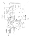
- FIGURE 1 there is shown a schematic view of an exemplary glass manufacturing system 100 that uses the fusion process to make glass sheets 137 in accordance with the present invention.
- the glass manufacturing system 100 includes a melting vessel 110 in which batch materials are introduced as shown by arrow 112 and then melted to form molten glass 114.
- the melting vessel 110 is typically made from a refractory material.
- the glass manufacturing system 100 further includes components that are typically made from platinum or platinum-containing metals such as Pt-Rh, Pt-Ir, etc, and combinations thereof.
- the platinum-containing components include a premelt to finer connection tube (PMFCT) 113, fining vessel 115 (e.g., finer tube 115), a mixing vessel 120 (e.g., stir chamber 120), a finer to stir chamber connecting tube 122, a delivery vessel 125 (e.g., bowl 125), a stir chamber to bowl connecting tube 127, a downcomer 130 and an inlet 132.
- the inlet 132 is coupled to a forming vessel 135 (e.g., fusion pipe 135) which forms the glass sheet 137.
- the forming vessel 135 is made from a refractory material.
- the melting/delivery system 141 which includes vessels 115, 120, 125 and tubes 122, 127 and 130 is encapsulated or encased within a capsule 140.
- a jacket volume 142 is defined between the interior walls of the capsule 140 and the exterior walls of the components 115, 120, 122, 125, 127 and 130 in the melting/delivery system 141.
- the capsule 140 is preferably leak tight to the extent that it may be used for maintaining a slightly more positive pressure of low oxygen, moist atmosphere inside the jacket volume 142 that is greater than the ambient conditions.
- the capsule 140 can be made as one zone which encloses the entire length of the melting/delivery system 141.
- multiple capsules 140 can be used as multiple zones where individual capsules 140 enclose one or more of the vessels 115, 120, 125 and tubes 122, 127 and 130.
- An advantage of utilizing multiple capsules 140 is the ability to independently control the atmosphere in a particular area of the melting/delivery system 141.
- the present invention also includes a closed-loop control system 144 which controls the environment/atmosphere within the capsule 140 and prevents the problematical oxidation reactions from occurring at the metal/glass interface inside components 115, 120, 122, 125, 127 and 130.
- the problematical oxidation reactions lead to the formation of gaseous inclusions in the glass sheet 137.
- problematical oxidation reactions with the precious metal vessels and tubes can lead to the failure of the platinum (or other precious metals) on the components 115, 120, 122, 125, 127 and 130.
- the closed-loop control system 144 controls the atmosphere inside the capsule 140 so as to suppress undesirable oxidation reactions at the metal/glass interface by causing the migration of hydrogen into the glass/metal interface.
- a controlled level of hydrogen permeation into the glass/metal interface reduces the production of undesirable species such as molecular oxygen, and halogens, which in turn prevents the formation of undesirable gaseous inclusions in the molten glass 114.
- the hydrogen permeation into the glass/metal interface is achieved by supplying a higher partial pressure of hydrogen to the exterior surfaces (non glass contact surfaces) in the mixing/delivery system 141, relative to the interior glass/metal interfaces.
- a humid, low oxygen atmosphere which results in a controlled level of hydrogen at the non-glass contact surface of the platinum system that is preferably greater than 12ppm at 1650°C, is maintained inside the capsule 140.
- the hydrogen level in the atmosphere inside the capsule 140 has an undetectable amount of hydrogen.
- hydrogen is generated when the water breaks down at the high temperatures associated with the molten glass 114.
- One gas system that could be used to create this atmosphere would be a mixture of water vapor, oxygen and nitrogen (or another inert gas like argon or helium).
- An exemplary closed-loop control system 144 that uses this gas system to create such an atmosphere inside the capsule 140 is described next.
- the exemplary closed-loop control system 144 includes a controller 150 that obtains sensor readings from one or more locations within and outside the capsule 140. As shown, the controller 150 can obtain sensor readings from capsule supply sensors 152, capsule sensors 154 and capsule exit sensors 156 and 156'.
- the capsule supply sensors 152 include a flow sensor 152a, a dew point/humidity sensor 152b, a temperature sensor 152c, an oxygen sensor 152d, and a pressure sensor 152e.
- the capsule sensors 154 include a flow sensor 154a, a dew point/humidity sensor 154b, a temperature sensor 154c, an oxygen sensor 154d, and a pressure sensor 154e.
- the capsule exit sensors 156 and 156' each include a flow sensor 156a and 156a', a dew point/humidity sensor 156b and 156b', a temperature sensor 156c and 156c', an oxygen sensor 156d and 156d', and a pressure sensor 156e and 156e'
- the controller 150 processes the sensor measurements and controls different devices like a humidity feed system 158, a heating/cooling control system 160, air handler(s) 162 and an O 2 /N 2 makeup system 164.
- the air handler(s) 162 have access to air and steam. All of the devices 158, 160, 162 and 164 are connected to a network of pipes 166 which as shown is connected to the capsule 140.
- the controller 150 controls the devices 158, 160, 162 and 164 to create an environment/atmosphere inside the capsule 140 where the hydrogen which is generated by the decomposition of water vapor is done so at a rate that is equal to or greater than the rate of hydrogen permeation through the metal walls of components 115, 120, 122, 125, 127 and 130 that would be occurring if an ambient atmosphere were present at the non-glass contact surface of the components.
- the reduction of undesirable species such as molecular oxygen, and halogens within the molten glass 114 prevents the formation of undesirable gaseous inclusions in the molten glass 114.
- Another advantage of having a higher pressure of hydrogen is that the rate of oxidation of the platinum containing components 115, 120, 122, 125, 127 and 130 is reduced or possible eliminated due to the low level of oxygen inside the capsule 140.
- the level of hydrogen on the exterior surfaces of the platinum containing components 115, 120, 122, 125, 127 and 130 needs to be equal to or greater than the level of hydrogen on the inside surfaces of the components 115, 120, 122, 125, 127 and 130.
- the hydrogen level on the exterior surfaces of the platinum containing components 115, 120, 122, 125, 127 and 130 is determined by the thermodynamic equilibrium of the water decomposition reaction H 2 0 ⁇ H 2 + 1 ⁇ 2 O 2 .
- the free energy ( ⁇ G) for the water decomposition reaction is equal to 58,900-13.1T, where T is the temperature in degrees Kelvin and G is the free energy in calories per mole.
- K eq [(pH 2 )(pO 2 ) 1/2 ]pH 2 O.
- K eq [(pH 2 )(pO 2 ) 1/2 ]pH 2 O.
- K eq is equal to 2.47 ⁇ 10 -5 .
- pH 2 is calculated to be 1.59 ⁇ 10 -6 atmospheres (1.59 ppm).
- Table 1 shows the effect of water and oxygen level on the level of hydrogen at various temperatures in the enclosed environments of a traditional enclosure and the capsule 140.
- the traditional enclosure is a room size enclosure that was made in accordance with one embodiment of the invention in the aforementioned U.S. Patent No. 5,785,726 .
- the traditional enclosure ensures that the partial pressure of hydrogen outside components 115, 120, 122, 125, 127 and 130 in the melting/delivery system 141 is in an amount sufficient to prevent formation of oxygen blisters in the glass that is adjacent to the vessel/glass interface.
- the traditional enclosure successfully reduces the formation of gaseous inclusions in glass sheets it still has some drawbacks.
- the traditional enclosure is so large that it makes it difficult if not impossible to maintain a uniform environment around the components 115, 120, 122, 125, 127 and 130 in the melting/delivery system 141.
- the traditional enclosure is so large and the environment is so hot and humid that it can be uncomfortable to people that walk into the enclosure.
- the capsule 140 and closed-loop control system 144 of the present invention addresses these drawbacks and other drawbacks associated with the traditional enclosure.
- the capsule 140 is a relatively small enclosure that produces a small jacket volume 142 which facilitates better control of the atmosphere. This is due to fact that a probe reading (such as relative humidity or dew point temperature) for conditions inside the capsule 140 is more likely to be representative of conditions at the exterior metal surfaces of glass processing equipment because the volume in the capsule 140 is smaller than the volume in the traditional enclosure.
- a probe reading such as relative humidity or dew point temperature
- the capsule 140 and closed-loop control system 144 has a better chance of solving this problem.
- the capsule 140 and closed-loop control system 144 of the present invention is essentially an enhanced version of the traditional enclosure.
- the traditional enclosure uses a humidified air atmosphere around the metal portion of the melting/delivery system 141.
- the capsule 140 and closed-loop control system 114 create a low oxygen moist atmosphere which allows hydrogen levels one to two or more orders of magnitude greater than that which is possible with the use of a high dew point air atmosphere in the traditional enclosure.
- the creation of this low oxygen moist atmosphere also extends the range of glasses that can be protected from hydrogen permeation blistering.
- FIGURE 2 there is a graph which shows the amount of blister generation (area coverage of blisters on the glass contact surface of platinum) vs. hydrogen level in the atmosphere on the exterior (non glass contact surface) of a platinum apparatus.
- the low hydrogen levels commonly associated with the humid air atmosphere in the traditional enclosure had unacceptable blistering over a wide range of temperatures.
- the high hydrogen atmosphere associated with the capsule 140 and the closed-loop control system 144 was very effective in suppressing the blistering in glass.
- the traditional enclosure works well but the capsule 140 and the closed-loop control system 144 of the present invention work even better at allowing blister suppression over a broad range of temperatures and glasses.
- FIGURE 3 is a graph that illustrates this difference and other differences in terms of ppm hydrogen vs. temperature as they relate to different operating conditions within the traditional enclosure and the capsule 140.
- the area above the curve 302 is the area where the capsule 140 can operate but it would be difficult to operate the traditional enclosure.
- both the capsule 140 and the traditional enclosure can effectively operate in the area below the curve 302.
- FIGURE 4 An example of the impact that a moist, low oxygen atmosphere has on glass is shown in FIGURE 4 .
- the photograph in FIGURE 4 shows two glass samples that were melted in identical platinum vessels that were 0.005" thick for ten minutes at 1450°C.
- the glass on the right was melted using known techniques in a 20°C dew point air atmosphere, while the glass on the left was melted in accordance with the invention in a 20°C dew point atmosphere containing 0.01% oxygen.
- the platinum was peeled from the glass and modeling clay was pressed into the bubble areas. It is clear that the glass exposed to the reduced oxygen atmosphere, which had a higher level of hydrogen, had significantly less blisters than the glass tested in air.
- the closed-loop control system 144 controls the moist, low oxygen atmosphere within the capsule 140 to inhibit the generation of gaseous inclusions in the glass sheet 137.
- the closed-loop control system 144 accomplishes this by controlling a gas system that has a mixture of water vapor, oxygen and nitrogen within the capsule 140.
- the typical values of oxygen would be from 0.01% to 1%, water from 2 to 20%, with the balance of the gas being nitrogen (or another inert gas like argon).
- the gas system could be run as high as 21% oxygen and have a dew point as high as 93°C (200°F).
- a gas system with 0.01% oxygen and 20% water at a 93°C (200°F) dew point can give a range of hydrogen from 1 to 38,000 ppm at 1700°C.
- the mixture of gases introduced into the jacket volume 142 of the capsule 140 may include hydrocarbons (and oxygen), ammonia, cracked ammonia products and/or combustion products.
- the glass manufacturing system 100 can also incorporate two optional enhancements which are described next.
- the first enhancement involves the use of a constriction plate 174 (or similar device) within the capsule 140 that constricts the flow of gas over a certain section or sections of the mixing/delivery system 141.
- the constriction plate 174 is located at an end of the fining vessel 115 such that 95% (for example) of the gas is diverted into pipe 166a and 5% (for example) of the gas flows over the fining vessel 155 and exits through pipe 166b.
- This configuration enables one to design a laminar flow of gas within the capsule 140 which enhances the ability to control of the environment.
- the constriction plate 174 would not be needed if the capsule 141 was shaped such that less volume is present in a particular area between the mixing/delivery system 141 over which less gas flow would be desired.
- the second enhancement involves the use of pipe 166c which provides one way to cool one or more specific components 115, 120, 122, 125, 127 and 130 in melting/delivery system 141.
- the finer to stir chamber connecting tube 122 (FSC tube 122) is cooled.
- pipe 166c has one end 168a connected to the main pipe 166 at a location prior to entering the capsule 140.
- pipe 166c has another end 168b that is directly connected to an inlet 170 that provides gas flow around the FSC tube 122.
- the FSC tube 122 also has an outlet 172 through which the gas mixture from pipe 166c is directed back into the atmosphere within the capsule 140.
- the second enhancement is an important aspect of the present invention in that it helps one to better control the heat transfer in the glass manufacturing system 100. This heat transfer control can be done at the same time the present invention is used to control the atmosphere for hydrogen permeation control.
- the capsule 140 and the closed-loop control system 144 can be used to cool the components 115, 120, 122, 125, 127 and 130 in the melting/delivery system 141 even without the second enhancement.
- the present invention can be used to help cool the molten glass 114 when it is moved from high temperature conditions suitable for melting to lower temperature conditions suitable for forming. Typically, the glass 114 needs to be cooled about 400°C.
- the capsule 140 and closed-loop control system 144 uses forced convection which is related to the gas flow outside the components 115, 120, 122, 125, 127 and 130.
- the capsule 140 is relatively small and has openings at known locations which are used to connect to pipes 166, 166a, 166b and 166c, the heat transfer can be carefully controlled, and cooling performance can be replicated from one installation to the next. Moreover, the laminar flow associated with the first enhancement described above can also be used to help one better control the heat transfer.
- the traditional enclosure has difficulty controlling the heat transfer because the gas flow is uncontrolled and depends on the different local temperatures and air flows within the enclosed room.
- the local cooling rate on the mixing/delivery system 141 in the traditional enclosure can only be controlled by the raising or lowering of local zone electrical heating devices.
- the local cooling rate can be adjusted inside the capsule 140 by both heater power and gas flow rate. This allows a larger range of cooling control capacity for glass flow as indicated in TABLE 2.
- the traditional enclosure has a minimum glass flow boundary of 0.85X which occurs when the heater power reaches its maximum. And, the traditional enclosure has a maximum glass flow boundary of 1.2X which occurs when the heater power is turned back far enough that some circuits are turned off. If the circuits are turned off, then the effective control of cooling is lost.
- the capsule 140 enables these boundaries to be extended to 0.75X-1.35X (for example) when air cooling is also variable.
- the flow boundaries associated with the capsule 140 are dictated by cooling capacity, not by head loss or other considerations.
- the capsule 140 enables one to control the cooling by forced convection. This type of control is not possible in the traditional enclosure because the enclosed room is so large and personnel can enter and leave the enclosed room.
- FIGURE 5 there is a flowchart illustrating the basic steps of a method 500 for making a glass sheet 137 in accordance with the present invention.
- molten glass 114 is formed and processed within a melting vessel 110, a fining vessel 115, a mixing vessel 120, a delivery vessel 125, and a forming vessel 135.
- the capsule 140 is used to enclose one or more of these vessels 110, 115, 120, 125 and 135 and tubes 113, 122, 127 and 130.
- the capsule 140 encloses the vessels 110, 115, 120 and 125 and tubes 122, 127 and 130 which are associated with the melting/delivery system 141 (see FIGURE 1 ).
- the closed-loop control system 144 is used to create, monitor and control a humid, low oxygen atmosphere within the capsule 140.
- the closed-loop control system 144 is used to control the level of hydrogen within a mixture of gases so that at least 12ppm of hydrogen at 1650°C (for example)(see TABLE 1, and FIGURES 2-3 ) is present around the exteriors of the enclosed vessels 110, 115, 120 and 125 so as to reduce hydrogen permeation from the molten glass 114 and effectively suppress the formation of undesirable gaseous inclusions within the molten glass 114.
- the closed-loop control system 144 can be used to control the level of oxygen that is present around the exteriors of the enclosed vessels 110, 115, 120 and 125 so as to reduce the oxidation of the precious metal on the enclosed vessels 110, 115, 120 and 125 and tubes 122, 127 and 130.
- the closed-loop control system 144 can be used to control the cooling of the molten glass 114 while it travels from one of the vessels (fining vessel 115) to another one of the vessels (mixing vessel 120).
Landscapes
- Chemical & Material Sciences (AREA)
- Engineering & Computer Science (AREA)
- Materials Engineering (AREA)
- Organic Chemistry (AREA)
- Chemical Kinetics & Catalysis (AREA)
- Electrochemistry (AREA)
- General Chemical & Material Sciences (AREA)
- Glass Compositions (AREA)
- Glass Melting And Manufacturing (AREA)
- Joining Of Glass To Other Materials (AREA)
- Muffle Furnaces And Rotary Kilns (AREA)
Claims (15)
- Verfahren (500) zum Herstellen eines Glasprodukts (137), wobei das Verfahren folgende Schritte umfasst:- Formen und/oder Verarbeiten (502) von schmelzflüssigem Glas (114) in mindestens einem von Folgendem: einem Schmelzgefäß (110), einem Läuterungsgefäß (115), einem Zufuhrgefäß (125) und einem Formungsgefäß (135);- Bereitstellen (504) einer Kapsel (140) zum Umschließen mindestens eines der Gefäße; und- Aufrechthalten (506) einer Atmosphäre innerhalb der Kapsel und um eine Nicht-Glaskontaktfläche des mindestens einen Gefäßes, wobei der Schritt des Aufrechthaltens einer Atmosphäre des Weiteren Folgendes umfasst:• Regeln eines Wasserstoffanteils innerhalb eines Gasgemisches in der Atmosphäre dergestalt, dass ein Partialdruck um die Nicht-Glaskontaktfläche des mindestens einen Gefäßes auf oder über einem Wert gehalten wird, der durch die Gleichgewichtsbeziehung pH2 (PPM) = 78.000 × e ^ [ (-58.900 + 13,1T) /(1,987*T(°K)) ] definiert wird, um die Entstehung unerwünschter Gaseinschlüsse innerhalb des schmelzflüssigen Glases zu unterdrücken, wobei T eine Temperatur in Kelvin um die Nicht-Glaskontaktfläche des mindestens einen Gefäßes ist, wobei das Verfahren dadurch gekennzeichnet ist:dass der Schritt des Aufrechthaltens einer Atmosphäre des Weiteren den Schritt des Verwendens einer Zwangskonvektion umfasst, um ein Abkühlen des schmelzflüssigen Glases durch Regeln einer Gasströmungsrate und der Wärme des Gasgemisches innerhalb der Kapsel zu regeln, während das schmelzflüssige Glas aus einem des mindestens einen Gefäßes zu einem anderen des mindestens einen Gefäßes fließt.
- Verfahren nach Anspruch 1, wobei der Schritt des Aufrechthaltens einer Atmosphäre des Weiteren den Schritt des Regelns eines Sauerstoffwertes innerhalb des Gasgemisches um die Nicht-Glaskontaktfläche des mindestens einen Gefäßes umfasst, um die Oxidation eines Edelmetalls auf dem mindestens einen Gefäß zu reduzieren.
- Verfahren nach Anspruch 1, wobei das Gasgemisch zu bis zu 38.000 ppm Wasserstoff an der Nicht-Glaskontaktfläche des mindestens einen Gefäßes führt.
- Verfahren nach Anspruch 1, wobei das Gasgemisch auf einer Taupunkttemperatur von 93,3 °C (200°F) oder niedriger gehalten wird.
- Verfahren nach Anspruch 1, wobei das Gasgemisch einen Sauerstoffgehalt mit einem Wert von weniger als 21 Volumen-% hat.
- Verfahren nach Anspruch 1, wobei das Gasgemisch einen Sauerstoffgehalt von 0,01 bis 1 Volumen-% und einen Wasserdampfgehalt von 2 bis 20 Volumen-% hat, wobei der Rest im Wesentlichen ein Inertgas ist.
- Verfahren nach Anspruch 1, wobei das Gasgemisch gekrackte Ammoniakprodukte enthält.
- Verfahren nach Anspruch 1, das des Weiteren einen Schritt des Positionierens einer Verengungsplatte (174) um die Nicht-Glasoberfläche von einem des mindestens einen Gefäßes umfasst, die einen Strom des Gasgemisches über jenes Gefäß reduziert und einen Laminarstrom des Gasgemisches innerhalb der Kapsel bewirkt.
- Verfahren nach Anspruch 1, wobei der Schritt des Aufrechthaltens einer Atmosphäre das Regeln des Partialdrucks von Sauerstoff in der Atmosphäre auf unter 0,21 Atmosphären umfasst.
- Verfahren nach Anspruch 1, wobei der Schritt des Bereitstellens einer Kapsel zum Umschließen mindestens eines der Gefäße des Weiteren das Bereitstellen mehrerer Kapseln umfasst, wobei jede einzelne Kapsel eines oder mehrere des mindestens einen der Gefäße umschließt.
- Glasherstellungssystem (100) das Folgendes umfasst:- ein Schmelz- (110), Läuterungs- (115), Zufuhr- (125) und Formung- (135) Gefäß, wobei jedes Gefäß eine Innenwand umfasst, die mit schmelzflüssigem Glas (114) in Berührung steht;- eine Kapsel (140), die mindestens eines der Gefäße umschließt;- ein Regelkreissystem (144), das eine Umgebung innerhalb der Kapsel und um eine Nicht-Glaskontaktfläche des mindestens einen Gefäßes überwacht und regelt, und
wobei das Regelkreissystem in der Lage ist, einen Wasserstoffanteil innerhalb eines Gasgemisches in der Umgebung so zu regeln, dass ein Wasserstoffpartialdruck auf oder über einem Wert, der durch die Gleichgewichtsbeziehung pH2 (PPM) = 78.000 × e ^ [(-58.900 + 13,1 T)/(1,987*T(°K))] definiert wird, um die Nicht-Glaskontaktfläche des mindestens einen Gefäßes gehalten wird, um wirkungsvoll die Entstehung unerwünschter Gaseinschlüsse innerhalb des schmelzflüssigen Glases zu unterdrücken, wobei das Glasherstellungssystem dadurch gekennzeichnet ist, dass:das Regelkreissystem des Weiteren dafür eingerichtet ist, die Umgebung innerhalb der Kapsel mittels Zwangskonvektion zu regeln, um ein Abkühlen des schmelzflüssigen Glases durch Regeln einer Gasströmungsrate und der Wärme des Gasgemisches innerhalb der Kapsel zu regeln, während das schmelzflüssige Glas aus einem des mindestens einen Gefäßes zu einem anderen des mindestens einen Gefäßes fließt. - Glasherstellungssystem nach Anspruch 11, wobei das Regelkreissystem des Weiteren einen Sauerstoffwert innerhalb des Gasgemisches in der Umgebung um die Nicht-Glaskontaktfläche des mindestens einen Gefäßes umfasst, um die Oxidation eines Edelmetalls auf dem mindestens einen Gefäß zu reduzieren.
- Glasherstellungssystem nach Anspruch 11, wobei das Regelkreissystem des Weiteren ein Abkühlen des schmelzflüssigen Glases durch Regeln des Stromes der Atmosphäre innerhalb der Kapsel regelt, während das schmelzflüssige Glas aus einem des mindestens einen Gefäßes zu einem anderen des mindestens einen Gefäßes fließt.
- Glasherstellungssystem nach Anspruch 11, das des Weiteren einer Verengungsplatte (174) umfasst, die um die Nicht-Glaskontaktfläche von einem des mindestens einen Gefäßes angeordnet ist und die in der Lage ist, einen Strom des Gasgemisches über jenes Gefäß zu reduzieren, und die einen Laminarstrom des Gasgemisches innerhalb der Kapsel bewirkt.
- Glasherstellungssystem nach Anspruch 11, das des Weiteren mehrere Kapseln umfasst, wobei jede einzelne Kapsel eines oder mehrere des mindestens einen der Gefäße umschließt.
Applications Claiming Priority (2)
| Application Number | Priority Date | Filing Date | Title |
|---|---|---|---|
| US11/116,669 US20060242996A1 (en) | 2005-04-27 | 2005-04-27 | System and method for controlling the environment around one or more vessels in a glass manufacturing system |
| PCT/US2006/014863 WO2006115972A1 (en) | 2005-04-27 | 2006-04-19 | System and method for controlling the environment around one or more vessels in a glass manufacturing system |
Publications (2)
| Publication Number | Publication Date |
|---|---|
| EP1874696A1 EP1874696A1 (de) | 2008-01-09 |
| EP1874696B1 true EP1874696B1 (de) | 2014-04-02 |
Family
ID=36645640
Family Applications (1)
| Application Number | Title | Priority Date | Filing Date |
|---|---|---|---|
| EP06750813.5A Ceased EP1874696B1 (de) | 2005-04-27 | 2006-04-19 | System und verfahren zur steuerung der umgebung eines oder mehrerer behälter in einem glasherstellungssystem |
Country Status (7)
| Country | Link |
|---|---|
| US (4) | US20060242996A1 (de) |
| EP (1) | EP1874696B1 (de) |
| JP (3) | JP2008539160A (de) |
| KR (1) | KR101075290B1 (de) |
| CN (2) | CN101166696B (de) |
| TW (1) | TWI362372B (de) |
| WO (1) | WO2006115972A1 (de) |
Families Citing this family (69)
| Publication number | Priority date | Publication date | Assignee | Title |
|---|---|---|---|---|
| CN101208276B (zh) * | 2005-06-28 | 2012-04-25 | 康宁股份有限公司 | 硼硅铝酸盐玻璃的澄清 |
| TWI327559B (en) | 2005-12-08 | 2010-07-21 | Corning Inc | Method of eliminating blisters in a glass making process |
| DE102006003521B4 (de) * | 2006-01-24 | 2012-11-29 | Schott Ag | Vorrichtung und Verfahren zum kontinuierlichen Läutern von Gläsern mit hohen Reinheitsanforderungen |
| DE102006003531A1 (de) * | 2006-01-24 | 2007-08-02 | Schott Ag | Verfahren und Vorrichtung zum blasenfreien Transportieren, Homogenisieren und Konditionieren von geschmolzenem Glas |
| US7833919B2 (en) | 2006-02-10 | 2010-11-16 | Corning Incorporated | Glass compositions having high thermal and chemical stability and methods of making thereof |
| US7534734B2 (en) | 2006-11-13 | 2009-05-19 | Corning Incorporated | Alkali-free glasses containing iron and tin as fining agents |
| US8256951B2 (en) | 2006-12-21 | 2012-09-04 | Corning Incorporated | Stirrers for minimizing erosion of refractory metal vessels in a glass making system |
| US20090272150A1 (en) * | 2007-11-02 | 2009-11-05 | Lawrence Henry Kotacska | Corrosion-resistant cradle and castable materials for glass production |
| US8925353B2 (en) * | 2007-11-08 | 2015-01-06 | Corning Incorporated | Process and system for fining glass |
| US20090217708A1 (en) * | 2008-02-29 | 2009-09-03 | Gilbert Deangelis | Methods and apparatus for reducing platinum-group defects in sheet glass |
| US20100083704A1 (en) * | 2008-10-08 | 2010-04-08 | Paul Richard Grzesik | Methods and apparatus for manufacturing glass sheet |
| US8695378B2 (en) * | 2008-11-26 | 2014-04-15 | Corning Incorporated | Apparatus for making glass and methods |
| US8117868B2 (en) * | 2009-07-27 | 2012-02-21 | Corning Incorporated | Apparatus and methods for making glass |
| US8978419B2 (en) * | 2009-11-30 | 2015-03-17 | Corning Incorporated | Devices for controlling atmosphere over molten-glass free-surfaces |
| US8240170B2 (en) * | 2010-02-22 | 2012-08-14 | Corning Incorporated | Apparatus for sealing a joint between vessels for conveying molten glass |
| CN101935146B (zh) * | 2010-03-24 | 2012-07-04 | 东旭集团有限公司 | 铂金通道中玻璃液的处理方法 |
| US8650910B2 (en) * | 2010-08-23 | 2014-02-18 | Corning Incorporated | Apparatus for homogenizing a glass melt |
| US20120125050A1 (en) * | 2010-09-30 | 2012-05-24 | Avanstrate Inc. | Method for manufacturing glass plate |
| TWI567036B (zh) * | 2011-03-31 | 2017-01-21 | Avanstrate Inc | Manufacture of glass plates |
| US20130025323A1 (en) * | 2011-07-25 | 2013-01-31 | Lineman David M | Fiber-based gasket, glass manufacturing system, and method for reducing thermal cell induced blisters |
| US9073771B2 (en) * | 2012-06-15 | 2015-07-07 | Corning Incorporated | Integral capsule for blister suppression in molten glass |
| CN102898016A (zh) * | 2012-08-06 | 2013-01-30 | 彩虹显示器件股份有限公司 | 抑制tft‐lcd 基板玻璃气泡产生的装置及方法 |
| US9475720B2 (en) * | 2012-11-26 | 2016-10-25 | Corning Incorporated | System and method for restricting inward hydrogen permeation in a glass manufacturing system |
| US9725349B2 (en) | 2012-11-28 | 2017-08-08 | Corning Incorporated | Glass manufacturing apparatus and methods |
| JP5746381B2 (ja) * | 2012-11-29 | 2015-07-08 | AvanStrate株式会社 | ガラス基板の製造方法 |
| KR102169675B1 (ko) | 2013-02-15 | 2020-10-26 | 코닝 인코포레이티드 | 낮은 지르코니아 수준을 갖는 디스플레이 품질 유리 시트의 대량 생산 |
| WO2014157349A1 (ja) * | 2013-03-27 | 2014-10-02 | AvanStrate株式会社 | ガラス基板の製造方法及びガラス基板製造装置 |
| KR102225583B1 (ko) | 2013-04-29 | 2021-03-10 | 코닝 인코포레이티드 | 광기전력 모듈 패키지 |
| EP3004006B1 (de) | 2013-05-30 | 2021-08-04 | Corning Incorporated | Glaskeramiken mit niedrigem rhodiumgehalt |
| CN113060935A (zh) | 2013-08-15 | 2021-07-02 | 康宁股份有限公司 | 掺杂有碱金属和不含碱金属的硼铝硅酸盐玻璃 |
| WO2015023561A2 (en) | 2013-08-15 | 2015-02-19 | Corning Incorporated | Intermediate to high cte glasses and glass articles comprising the same |
| US9714188B2 (en) | 2013-09-13 | 2017-07-25 | Corning Incorporated | Ion exchangeable glasses with high crack initiation threshold |
| CN105431385B (zh) * | 2014-06-30 | 2018-10-09 | 安瀚视特控股株式会社 | 玻璃基板的制造方法、玻璃基板及玻璃基板层叠体 |
| KR102377995B1 (ko) * | 2014-09-29 | 2022-03-23 | 코닝 인코포레이티드 | 유리 유입구 튜브 환경 제어 |
| KR102559221B1 (ko) | 2014-10-31 | 2023-07-25 | 코닝 인코포레이티드 | 치수적으로 안정한 급속 에칭 유리 |
| KR101809114B1 (ko) | 2014-10-31 | 2017-12-14 | 주식회사 엘지화학 | 유리 제조 장치 |
| CN104671638B (zh) * | 2014-12-31 | 2017-08-29 | 彩虹(合肥)液晶玻璃有限公司 | 一种控制贵金属通道气氛条件的系统及方法 |
| JP6051239B2 (ja) * | 2015-01-27 | 2016-12-27 | 株式会社フルヤ金属 | ガラス製造装置の成形部 |
| US9586846B2 (en) * | 2015-04-13 | 2017-03-07 | Corning Incorporated | Apparatus and methods for processing molten material |
| US10501358B2 (en) | 2015-05-06 | 2019-12-10 | Corning Incorporated | Apparatus and methods for processing molten material |
| WO2016178964A2 (en) * | 2015-05-06 | 2016-11-10 | Corning Incorporated | Apparatus and method for conditioning molten glass |
| CN107922232B (zh) | 2015-06-10 | 2020-12-08 | 康宁股份有限公司 | 用于调整熔融玻璃的设备和方法 |
| WO2017063666A1 (de) * | 2015-10-12 | 2017-04-20 | Emp-Glass Gmbh | Vorrichtung zur erzeugung einer dampfhaltigen gasatmosphäre und anlagenkomponente mit einer solchen vorrichtung |
| TW201728540A (zh) * | 2015-11-05 | 2017-08-16 | 康寧公司 | 減少顆粒黏著的玻璃製造方法 |
| US9758418B1 (en) | 2016-04-06 | 2017-09-12 | Corning Incorporated | Methods of producing glass ribbon |
| DE102016109974A1 (de) * | 2016-05-31 | 2017-11-30 | Schott Ag | Verfahren zur Herstellung eines Glasproduktes sowie verfahrensgemäß erhaltenes Glasprodukt |
| US9828283B1 (en) | 2016-07-29 | 2017-11-28 | Corning Incorporated | Kanoite glass-ceramics |
| EP3526171B1 (de) | 2016-10-12 | 2023-12-13 | Corning Incorporated | Glaskeramik |
| TW201819318A (zh) * | 2016-10-31 | 2018-06-01 | 美商康寧公司 | 用於形成玻璃帶的玻璃製造設備及方法 |
| TWI746726B (zh) * | 2016-12-15 | 2021-11-21 | 美商康寧公司 | 用於控制流入玻璃成形機之玻璃流的方法及設備 |
| JP7113827B2 (ja) | 2016-12-29 | 2022-08-05 | コーニング インコーポレイテッド | 耐ソラリゼーション性の希土類ドープガラス |
| JP7171600B2 (ja) * | 2017-03-16 | 2022-11-15 | コーニング インコーポレイテッド | ガラス溶融物の表面上の気泡の寿命を減少させる方法 |
| JP7084948B2 (ja) * | 2017-06-06 | 2022-06-15 | コーニング インコーポレイテッド | ガラス製造システムの再調整方法 |
| CN111344260B (zh) | 2017-11-21 | 2022-08-02 | Agc株式会社 | 熔融玻璃运送装置、玻璃制造装置以及玻璃制造方法 |
| KR102405740B1 (ko) * | 2018-01-11 | 2022-06-08 | 코닝 인코포레이티드 | 유리 제조 장치 및 유리 제조 방법 |
| TWI809029B (zh) | 2018-01-15 | 2023-07-21 | 美商康寧公司 | 尺度上穩定快速地蝕刻玻璃 |
| US10807896B2 (en) * | 2018-03-15 | 2020-10-20 | Owens-Brockway Glass Container Inc. | Process and apparatus for glass manufacture |
| EP3781526B1 (de) * | 2018-04-20 | 2022-12-14 | Corning Incorporated | Vorrichtung und verfahren zur steuerung einer sauerstoff enthaltenden atmosphäre in einem glasherstellungsverfahren |
| CN116062992A (zh) | 2018-06-19 | 2023-05-05 | 康宁公司 | 高应变点且高杨氏模量玻璃 |
| WO2020112348A1 (en) * | 2018-11-28 | 2020-06-04 | Corning Incorporated | Method of controlling bubbles in a glass making process |
| WO2020191275A1 (en) * | 2019-03-20 | 2020-09-24 | Air Products And Chemicals, Inc. | Method for tin bath monitoring and control |
| JP7159972B2 (ja) | 2019-05-22 | 2022-10-25 | Agc株式会社 | 溶融ガラス搬送装置、ガラス製造装置及びガラス製造方法 |
| US11459263B2 (en) * | 2019-10-01 | 2022-10-04 | Owens-Brockway Glass Container Inc. | Selective chemical fining of small bubbles in glass |
| US11773001B2 (en) | 2019-12-17 | 2023-10-03 | Ohmium International, Inc. | Systems and methods of electrochemical hydrogen generation to provide a reducing ambient for industrial fabrication |
| WO2021202102A1 (en) * | 2020-03-30 | 2021-10-07 | Corning Incorporated | Apparatus and method for reducing defects in glass melt systems |
| DE102020205045B4 (de) * | 2020-04-21 | 2024-07-04 | Schott Ag | Vorrichtung zum Schmelzen und Läutern von Glas sowie Verfahren zum Herstellen einer solchen Vorrichtung |
| KR102916905B1 (ko) * | 2020-08-24 | 2026-01-26 | 코닝 인코포레이티드 | 귀금속 시스템에서 제조된 유리에서의 결정질 로듐-백금 결함 형성의 최소화 |
| CN115228334B (zh) * | 2022-07-07 | 2024-03-29 | 河北光兴半导体技术有限公司 | 玻璃基板产线料道搅拌内流场模拟装置及模拟系统 |
| CN116332479B (zh) * | 2023-02-14 | 2024-10-29 | 彩虹(合肥)液晶玻璃有限公司 | Tft玻璃加工用铂金通道防氧化控制装置及方法 |
Family Cites Families (15)
| Publication number | Priority date | Publication date | Assignee | Title |
|---|---|---|---|---|
| US3338696A (en) * | 1964-05-06 | 1967-08-29 | Corning Glass Works | Sheet forming apparatus |
| US3607166A (en) * | 1968-05-06 | 1971-09-21 | Sylvania Electric Prod | Manufacture of striation-free quartz tubing |
| BE757057A (fr) * | 1969-10-06 | 1971-04-05 | Corning Glass Works | Procede et appareil de controle d'epaisseur d'une feuille de verre nouvellement etiree |
| US3970442A (en) * | 1975-07-16 | 1976-07-20 | Ppg Industries, Inc. | Method of introducing protective atmosphere gases into a glass forming chamber |
| US4351664A (en) * | 1981-03-16 | 1982-09-28 | Corning Glass Works | Furnace delivery system |
| EP0891306B1 (de) * | 1996-04-04 | 2005-08-24 | Corning Incorporated | Methode zur Bildung von strukturierter Färbung durch Reduktion in Glas mit Hilfe einer strukturierten Barriereschicht |
| US5824127A (en) * | 1996-07-19 | 1998-10-20 | Corning Incorporated | Arsenic-free glasses |
| US5785726A (en) * | 1996-10-28 | 1998-07-28 | Corning Incorporated | Method of reducing bubbles at the vessel/glass interface in a glass manufacturing system |
| DE19955827B4 (de) * | 1999-11-20 | 2005-03-31 | Schott Ag | Verfahren zur Unterdrückung der Bildung von O2-Gasblasen an der Kontaktfläche zwischen einer Glasschmelze und Edelmetall |
| US6748765B2 (en) * | 2000-05-09 | 2004-06-15 | Richard B. Pitbladdo | Overflow downdraw glass forming method and apparatus |
| US7338714B2 (en) * | 2000-11-30 | 2008-03-04 | Schott Ag | Coated metal element used for producing glass |
| US7032412B2 (en) * | 2003-03-13 | 2006-04-25 | Corning Incorporated | Methods of manufacturing glass sheets with reduced blisters |
| US6993936B2 (en) * | 2003-09-04 | 2006-02-07 | Corning Incorporated | System and method for suppressing the formation of oxygen inclusions and surface blisters in glass sheets and the resulting glass sheets |
| DE10348466B4 (de) * | 2003-10-14 | 2007-05-31 | Schott Ag | Vorrichtung und Verfahren zur Herstellung von hoch schmelzenden Gläsern oder Glaskeramiken und Verwendung einer Vorrichtung |
| US7584632B2 (en) * | 2005-07-28 | 2009-09-08 | Corning Incorporated | Method of increasing the effectiveness of a fining agent in a glass melt |
-
2005
- 2005-04-27 US US11/116,669 patent/US20060242996A1/en not_active Abandoned
-
2006
- 2006-04-19 KR KR1020077027661A patent/KR101075290B1/ko not_active Expired - Lifetime
- 2006-04-19 EP EP06750813.5A patent/EP1874696B1/de not_active Ceased
- 2006-04-19 WO PCT/US2006/014863 patent/WO2006115972A1/en not_active Ceased
- 2006-04-19 CN CN2006800146079A patent/CN101166696B/zh not_active Expired - Lifetime
- 2006-04-19 JP JP2008508932A patent/JP2008539160A/ja active Pending
- 2006-04-19 CN CN201210336960.6A patent/CN102838266B/zh not_active Expired - Lifetime
- 2006-04-21 TW TW095114795A patent/TWI362372B/zh active
-
2009
- 2009-01-30 US US12/362,738 patent/US7628038B2/en not_active Expired - Lifetime
- 2009-02-05 US US12/366,245 patent/US7628039B2/en not_active Expired - Lifetime
- 2009-10-23 US US12/604,873 patent/US20100192633A1/en not_active Abandoned
-
2013
- 2013-03-18 JP JP2013054888A patent/JP5815585B2/ja not_active Expired - Lifetime
- 2013-03-18 JP JP2013054889A patent/JP5723405B2/ja not_active Expired - Lifetime
Also Published As
| Publication number | Publication date |
|---|---|
| KR20080003930A (ko) | 2008-01-08 |
| CN102838266B (zh) | 2015-02-04 |
| WO2006115972A1 (en) | 2006-11-02 |
| EP1874696A1 (de) | 2008-01-09 |
| US7628039B2 (en) | 2009-12-08 |
| US20090126405A1 (en) | 2009-05-21 |
| JP5815585B2 (ja) | 2015-11-17 |
| CN101166696B (zh) | 2012-10-31 |
| KR101075290B1 (ko) | 2011-10-19 |
| JP2013173665A (ja) | 2013-09-05 |
| US7628038B2 (en) | 2009-12-08 |
| US20090241602A1 (en) | 2009-10-01 |
| TWI362372B (en) | 2012-04-21 |
| CN102838266A (zh) | 2012-12-26 |
| JP2013116852A (ja) | 2013-06-13 |
| JP2008539160A (ja) | 2008-11-13 |
| JP5723405B2 (ja) | 2015-05-27 |
| TW200706507A (en) | 2007-02-16 |
| US20100192633A1 (en) | 2010-08-05 |
| US20060242996A1 (en) | 2006-11-02 |
| CN101166696A (zh) | 2008-04-23 |
Similar Documents
| Publication | Publication Date | Title |
|---|---|---|
| US7628039B2 (en) | System and method for controlling the environmental around one or more vessels in a glass manufacturing system | |
| EP2311780A2 (de) | Verfahren zur Vermeidung von Blasen bei einem Glasherstellungsverfahren | |
| KR101474957B1 (ko) | 유리 제조 장치 | |
| US20060086146A1 (en) | System and method for suppressing the formation of oxygen inclusions and surface blisters in glass sheets and the resulting glass sheets | |
| KR101737128B1 (ko) | 유리 제조 장치를 위한 백금-함유 요소의 탄소 오염물 제거 방법 | |
| US11505487B2 (en) | Method for decreasing bubble lifetime on a glass melt surface | |
| KR101650215B1 (ko) | 유리 시트 제조용 방법 및 장치 | |
| TWI890028B (zh) | 用於在玻璃製造製程中控制含氧氣氛的設備及方法 | |
| JP7837645B2 (ja) | ガラス溶融システムにおいて欠陥を低減するための装置及び方法 |
Legal Events
| Date | Code | Title | Description |
|---|---|---|---|
| PUAI | Public reference made under article 153(3) epc to a published international application that has entered the european phase |
Free format text: ORIGINAL CODE: 0009012 |
|
| 17P | Request for examination filed |
Effective date: 20071017 |
|
| AK | Designated contracting states |
Kind code of ref document: A1 Designated state(s): DE FR |
|
| DAX | Request for extension of the european patent (deleted) | ||
| RBV | Designated contracting states (corrected) |
Designated state(s): DE FR |
|
| 17Q | First examination report despatched |
Effective date: 20080721 |
|
| GRAP | Despatch of communication of intention to grant a patent |
Free format text: ORIGINAL CODE: EPIDOSNIGR1 |
|
| INTG | Intention to grant announced |
Effective date: 20131106 |
|
| GRAS | Grant fee paid |
Free format text: ORIGINAL CODE: EPIDOSNIGR3 |
|
| GRAA | (expected) grant |
Free format text: ORIGINAL CODE: 0009210 |
|
| AK | Designated contracting states |
Kind code of ref document: B1 Designated state(s): DE FR |
|
| REG | Reference to a national code |
Ref country code: DE Ref legal event code: R096 Ref document number: 602006040920 Country of ref document: DE Effective date: 20140515 |
|
| REG | Reference to a national code |
Ref country code: DE Ref legal event code: R097 Ref document number: 602006040920 Country of ref document: DE |
|
| PLBE | No opposition filed within time limit |
Free format text: ORIGINAL CODE: 0009261 |
|
| STAA | Information on the status of an ep patent application or granted ep patent |
Free format text: STATUS: NO OPPOSITION FILED WITHIN TIME LIMIT |
|
| 26N | No opposition filed |
Effective date: 20150106 |
|
| REG | Reference to a national code |
Ref country code: DE Ref legal event code: R097 Ref document number: 602006040920 Country of ref document: DE Effective date: 20150106 |
|
| REG | Reference to a national code |
Ref country code: FR Ref legal event code: PLFP Year of fee payment: 11 |
|
| REG | Reference to a national code |
Ref country code: FR Ref legal event code: PLFP Year of fee payment: 12 |
|
| REG | Reference to a national code |
Ref country code: FR Ref legal event code: PLFP Year of fee payment: 13 |
|
| PGFP | Annual fee paid to national office [announced via postgrant information from national office to epo] |
Ref country code: FR Payment date: 20230320 Year of fee payment: 18 |
|
| PGFP | Annual fee paid to national office [announced via postgrant information from national office to epo] |
Ref country code: DE Payment date: 20230320 Year of fee payment: 18 |
|
| REG | Reference to a national code |
Ref country code: DE Ref legal event code: R119 Ref document number: 602006040920 Country of ref document: DE |
|
| PG25 | Lapsed in a contracting state [announced via postgrant information from national office to epo] |
Ref country code: DE Free format text: LAPSE BECAUSE OF NON-PAYMENT OF DUE FEES Effective date: 20241105 |
|
| PG25 | Lapsed in a contracting state [announced via postgrant information from national office to epo] |
Ref country code: FR Free format text: LAPSE BECAUSE OF NON-PAYMENT OF DUE FEES Effective date: 20240430 |
|
| PG25 | Lapsed in a contracting state [announced via postgrant information from national office to epo] |
Ref country code: FR Free format text: LAPSE BECAUSE OF NON-PAYMENT OF DUE FEES Effective date: 20240430 Ref country code: DE Free format text: LAPSE BECAUSE OF NON-PAYMENT OF DUE FEES Effective date: 20241105 |