EP1873339A2 - Türanlage - Google Patents
Türanlage Download PDFInfo
- Publication number
- EP1873339A2 EP1873339A2 EP07111113A EP07111113A EP1873339A2 EP 1873339 A2 EP1873339 A2 EP 1873339A2 EP 07111113 A EP07111113 A EP 07111113A EP 07111113 A EP07111113 A EP 07111113A EP 1873339 A2 EP1873339 A2 EP 1873339A2
- Authority
- EP
- European Patent Office
- Prior art keywords
- profile
- web
- hood
- door system
- base
- Prior art date
- Legal status (The legal status is an assumption and is not a legal conclusion. Google has not performed a legal analysis and makes no representation as to the accuracy of the status listed.)
- Granted
Links
Images

Classifications
-
- E—FIXED CONSTRUCTIONS
- E05—LOCKS; KEYS; WINDOW OR DOOR FITTINGS; SAFES
- E05D—HINGES OR SUSPENSION DEVICES FOR DOORS, WINDOWS OR WINGS
- E05D15/00—Suspension arrangements for wings
- E05D15/06—Suspension arrangements for wings for wings sliding horizontally more or less in their own plane
- E05D15/0621—Details, e.g. suspension or supporting guides
- E05D15/0626—Details, e.g. suspension or supporting guides for wings suspended at the top
- E05D15/0652—Tracks
-
- E—FIXED CONSTRUCTIONS
- E05—LOCKS; KEYS; WINDOW OR DOOR FITTINGS; SAFES
- E05D—HINGES OR SUSPENSION DEVICES FOR DOORS, WINDOWS OR WINGS
- E05D1/00—Pinless hinges; Substitutes for hinges
- E05D1/04—Pinless hinges; Substitutes for hinges with guide members shaped as circular arcs
-
- E—FIXED CONSTRUCTIONS
- E05—LOCKS; KEYS; WINDOW OR DOOR FITTINGS; SAFES
- E05F—DEVICES FOR MOVING WINGS INTO OPEN OR CLOSED POSITION; CHECKS FOR WINGS; WING FITTINGS NOT OTHERWISE PROVIDED FOR, CONCERNED WITH THE FUNCTIONING OF THE WING
- E05F15/00—Power-operated mechanisms for wings
- E05F15/60—Power-operated mechanisms for wings using electrical actuators
- E05F15/603—Power-operated mechanisms for wings using electrical actuators using rotary electromotors
- E05F15/632—Power-operated mechanisms for wings using electrical actuators using rotary electromotors for horizontally-sliding wings
-
- E—FIXED CONSTRUCTIONS
- E05—LOCKS; KEYS; WINDOW OR DOOR FITTINGS; SAFES
- E05Y—INDEXING SCHEME ASSOCIATED WITH SUBCLASSES E05D AND E05F, RELATING TO CONSTRUCTION ELEMENTS, ELECTRIC CONTROL, POWER SUPPLY, POWER SIGNAL OR TRANSMISSION, USER INTERFACES, MOUNTING OR COUPLING, DETAILS, ACCESSORIES, AUXILIARY OPERATIONS NOT OTHERWISE PROVIDED FOR, APPLICATION THEREOF
- E05Y2201/00—Constructional elements; Accessories therefor
- E05Y2201/10—Covers; Housings
-
- E—FIXED CONSTRUCTIONS
- E05—LOCKS; KEYS; WINDOW OR DOOR FITTINGS; SAFES
- E05Y—INDEXING SCHEME ASSOCIATED WITH SUBCLASSES E05D AND E05F, RELATING TO CONSTRUCTION ELEMENTS, ELECTRIC CONTROL, POWER SUPPLY, POWER SIGNAL OR TRANSMISSION, USER INTERFACES, MOUNTING OR COUPLING, DETAILS, ACCESSORIES, AUXILIARY OPERATIONS NOT OTHERWISE PROVIDED FOR, APPLICATION THEREOF
- E05Y2201/00—Constructional elements; Accessories therefor
- E05Y2201/10—Covers; Housings
- E05Y2201/11—Covers
-
- E—FIXED CONSTRUCTIONS
- E05—LOCKS; KEYS; WINDOW OR DOOR FITTINGS; SAFES
- E05Y—INDEXING SCHEME ASSOCIATED WITH SUBCLASSES E05D AND E05F, RELATING TO CONSTRUCTION ELEMENTS, ELECTRIC CONTROL, POWER SUPPLY, POWER SIGNAL OR TRANSMISSION, USER INTERFACES, MOUNTING OR COUPLING, DETAILS, ACCESSORIES, AUXILIARY OPERATIONS NOT OTHERWISE PROVIDED FOR, APPLICATION THEREOF
- E05Y2600/00—Mounting or coupling arrangements for elements provided for in this subclass
- E05Y2600/10—Adjustable
- E05Y2600/30—Adjustment motion
- E05Y2600/32—Rotary motion
- E05Y2600/322—Rotary motion around a horizontal axis
-
- E—FIXED CONSTRUCTIONS
- E05—LOCKS; KEYS; WINDOW OR DOOR FITTINGS; SAFES
- E05Y—INDEXING SCHEME ASSOCIATED WITH SUBCLASSES E05D AND E05F, RELATING TO CONSTRUCTION ELEMENTS, ELECTRIC CONTROL, POWER SUPPLY, POWER SIGNAL OR TRANSMISSION, USER INTERFACES, MOUNTING OR COUPLING, DETAILS, ACCESSORIES, AUXILIARY OPERATIONS NOT OTHERWISE PROVIDED FOR, APPLICATION THEREOF
- E05Y2600/00—Mounting or coupling arrangements for elements provided for in this subclass
- E05Y2600/60—Mounting or coupling members; Accessories therefor
-
- E—FIXED CONSTRUCTIONS
- E05—LOCKS; KEYS; WINDOW OR DOOR FITTINGS; SAFES
- E05Y—INDEXING SCHEME ASSOCIATED WITH SUBCLASSES E05D AND E05F, RELATING TO CONSTRUCTION ELEMENTS, ELECTRIC CONTROL, POWER SUPPLY, POWER SIGNAL OR TRANSMISSION, USER INTERFACES, MOUNTING OR COUPLING, DETAILS, ACCESSORIES, AUXILIARY OPERATIONS NOT OTHERWISE PROVIDED FOR, APPLICATION THEREOF
- E05Y2800/00—Details, accessories and auxiliary operations not otherwise provided for
- E05Y2800/15—Applicability
- E05Y2800/16—Applicable on combinations of fixed and movable wings
-
- E—FIXED CONSTRUCTIONS
- E05—LOCKS; KEYS; WINDOW OR DOOR FITTINGS; SAFES
- E05Y—INDEXING SCHEME ASSOCIATED WITH SUBCLASSES E05D AND E05F, RELATING TO CONSTRUCTION ELEMENTS, ELECTRIC CONTROL, POWER SUPPLY, POWER SIGNAL OR TRANSMISSION, USER INTERFACES, MOUNTING OR COUPLING, DETAILS, ACCESSORIES, AUXILIARY OPERATIONS NOT OTHERWISE PROVIDED FOR, APPLICATION THEREOF
- E05Y2800/00—Details, accessories and auxiliary operations not otherwise provided for
- E05Y2800/26—Form or shape
- E05Y2800/27—Profiles; Strips
-
- E—FIXED CONSTRUCTIONS
- E05—LOCKS; KEYS; WINDOW OR DOOR FITTINGS; SAFES
- E05Y—INDEXING SCHEME ASSOCIATED WITH SUBCLASSES E05D AND E05F, RELATING TO CONSTRUCTION ELEMENTS, ELECTRIC CONTROL, POWER SUPPLY, POWER SIGNAL OR TRANSMISSION, USER INTERFACES, MOUNTING OR COUPLING, DETAILS, ACCESSORIES, AUXILIARY OPERATIONS NOT OTHERWISE PROVIDED FOR, APPLICATION THEREOF
- E05Y2800/00—Details, accessories and auxiliary operations not otherwise provided for
- E05Y2800/26—Form or shape
- E05Y2800/29—Form or shape forming a unitary piece with another element
-
- E—FIXED CONSTRUCTIONS
- E05—LOCKS; KEYS; WINDOW OR DOOR FITTINGS; SAFES
- E05Y—INDEXING SCHEME ASSOCIATED WITH SUBCLASSES E05D AND E05F, RELATING TO CONSTRUCTION ELEMENTS, ELECTRIC CONTROL, POWER SUPPLY, POWER SIGNAL OR TRANSMISSION, USER INTERFACES, MOUNTING OR COUPLING, DETAILS, ACCESSORIES, AUXILIARY OPERATIONS NOT OTHERWISE PROVIDED FOR, APPLICATION THEREOF
- E05Y2800/00—Details, accessories and auxiliary operations not otherwise provided for
- E05Y2800/74—Specific positions
- E05Y2800/742—Specific positions abnormal
-
- E—FIXED CONSTRUCTIONS
- E05—LOCKS; KEYS; WINDOW OR DOOR FITTINGS; SAFES
- E05Y—INDEXING SCHEME ASSOCIATED WITH SUBCLASSES E05D AND E05F, RELATING TO CONSTRUCTION ELEMENTS, ELECTRIC CONTROL, POWER SUPPLY, POWER SIGNAL OR TRANSMISSION, USER INTERFACES, MOUNTING OR COUPLING, DETAILS, ACCESSORIES, AUXILIARY OPERATIONS NOT OTHERWISE PROVIDED FOR, APPLICATION THEREOF
- E05Y2900/00—Application of doors, windows, wings or fittings thereof
- E05Y2900/10—Application of doors, windows, wings or fittings thereof for buildings or parts thereof
- E05Y2900/13—Type of wing
- E05Y2900/132—Doors
Definitions
- the invention relates to a door system according to the preamble of patent claim 1.
- the housing has a base profile and a hood profile, wherein the hood profile can be detachably mounted on the base profile in a fastening region in that the hood profile has a coupling surface which can be suspended in a receiving surface of the base profile.
- the coupling surface and the receiving surface form a hinge, by being formed so that the hood profile is pivotable relative to the base profile.
- a locking device with which the hood profile can be locked in at least one pivotal position relative to the base profile.
- the locking device is arranged far outside the attachment region and comprises a locking lug which can be mounted on a limb of the base profile and which cooperates with a latching tongue integrally formed on the hood profile.
- the locking device By means of the locking device, the hood profile can be locked in its closed position relative to the base profile. A locking of the base profile in other, deviating from the closed position positions is not possible with this locking device.
- this locking device is complicated by the addition to be assembled components in the assembly.
- the invention has for its object to provide a door system with a housing, the locking device for the hood profile is structurally simple and easy to handle.
- the locking device is formed in the hinge. This arrangement is characterized by a simple structure, because it requires no additional components or large installation space. Furthermore, no tools or other aids are required for locking the hood profile in deviating from the closed position positions.
- the receiving surface of the base profile may have a concave cross section
- the coupling surface of the hood profile may have a convex cross section and the radii of the receiving surface and the coupling surface are at least approximately equal and are arranged with a common center.
- a web On the base profile, a web may be integrally formed with at least one groove, wherein the web has a substantially circular segment-shaped cross-section and the center of the radius of the outer side of the web is at least approximately equal to the center of the radius of the receiving surface.
- a web On the hood profile, a web can be formed with a projection, wherein this web has a substantially circular segment-shaped cross section and the center of the radius of the inside of the web is at least approximately equal to the center of the radius of the coupling surface.
- the radius of the inside of the web of the hood profile is slightly larger than the radius of the outside of the web of the base profile, so that when mounted hood profile of the web of the hood profile can overlap the web of the base profile.
- the web of the hood profile may have a defined elasticity.
- the projection of the web of the hood profile engages in a groove of the web of the basic profile.
- the projection of the web of the hood profile engages with an open hood profile of the projection of the web of the hood profile in another groove of the web of the base profile.
- the projection of the web of the hood profile slides in not fully open or closed hood profile on the Surface of the web of the base profile, wherein the web of the hood profile is then elastically deformed and the engagement of the projection takes place latching in one of the grooves of the base profile.
- the application of a force for elastic deformation of the projection-bearing web is required.
- the locking device thus offers an extended functionality, since it easily allows the locking of the hood profile in several positions by a groove can be provided in the web of the base profile for each locking position of the hood profile.
- the web of the base profile may have in its center a flattening or indentation in the cooperating with the projection of the hood profile surface.
- the projection is at about half open hood profile in the region of the flattening or indentation of the web of the base profile.
- the coupling surface of the hood profile can therefore only be suspended from the receiving surface of the base profile or can be suspended in this case when the hood profile is approximately half open. In the other positions of the hood profile this is protected by the previously described sliding of the projection of the hood profile on the surface of the web of the base profile against unwanted unhooking.
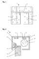
- Fig. 1 designed as a sliding door system door system 1 is shown in front view.
- the door system 1 has two counter-driven, guided in a running rail sliding sash 3.
- the lockable through the sliding panel 3 passage area of the door system 1 is limited by two fixed fields 4.
- the automatic drive of the sliding sash 3 takes place by means of a drive device 2 arranged in the upper region of the door system 1.
- the housing of the drive device 2 has a basic profile 5 and a hood profile 7 which can be mounted thereon.
- a running rail 6 is integrally formed in the lower region, on which the rollers 10 of the sliding blades 3 supporting roller carriage 9 roll.
- the running rail 6 may also be formed as a separate profile.
- a drive motor 12 is arranged in this sectional plane, which can be mounted by means of a fastener 13 to one of the mounting portions 11 of the base section 5.
- the mounting portion 11 is formed in this embodiment as an undercut groove in which the fastening element 13 designed as a sliding block can be fixed.
- the drive motor 12 acts via a transmission, not shown, as well as via a power transmission device, also not shown, for example, a rotating drive belt, with the sliding sash 3 together.
- Other components of the drive device 2 (not shown) can also be mounted on the mounting portions 11 of the base profile 5.
- the hood profile 7 is pivotable relative to the base profile 5 and removable from this.
- the pivoted position of the hood profile 7 is shown in FIG .
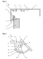
- the design of the hinge 8 between the base profile 5 and the hood profile 7 is shown only schematically in FIGS. 2 and 3 by the circle. 4 to 6 , the area of the hinge 8 between the base profile 5 and the hood profile 7 with different positions of the hood profile 7, however, is shown enlarged:
- the base profile 5 has on its the hood profile 7 facing end side obliquely upwardly directed receiving surface 16 for a coupling surface 18 of the hood profile 7. While the receiving surface 16 has a concave, approximately quarter-circular cross-section, the coupling surface 18 is convex, i. formed with spherical head cross-section with the same radius.
- the coupling surface 18 of the hood profile 7 is thus inserted obliquely from above into the receiving surface 16 and can be brought into positive engagement with the receiving surface 16.
- the at least approximately equality of the radii of the coupling surface 18 and the receiving surface 16 makes it possible to pivot the hood profile 7 relative to the base profile 5, without the positive connection between the coupling surface 18 and the receiving surface 16 having to be canceled.
- the base profile 5 and the hood profile 7 each have a web 14, 19.
- the webs 14, 19 each have a quarter-circle-shaped cross-section, wherein the centers of the circle radii are at least approximately congruent with the center of the radius of the coupling surface 18.
- the web 19 of the hood profile 7 is formed on the vertical leg of the hood profile 7 and extends to the base profile 5 out obliquely above.
- the web 14 of the base section 5 is arranged in the region of the hood profile 7 directed end edge of the base section 5 and extends to the hood profile 7 out obliquely downwards.
- the web 19 of the hood profile 7 has a slightly larger radius than the web 14 of the base profile 5, so that it overlaps the web 14 of the basic profile 5. While the web 14 of the basic profile 5 is rigid, the web 19 of the hood profile 7 has a low elasticity, the influence of which will be described below.
- At its upper end a directed to the web of the base profile 5 projection 20 is integrally formed on the web 19 of the hood profile 7, which can engage in one of the complementarily shaped, directed to the web 19 of the hood profile 7 grooves 21, 22 in the web 14 of the base section 5.
- the web 14 of the base profile 5 a directed to the web 19 of the hood profile 7 flattening 23. This serves for the insertion and removal of the hood profile 7, as shown in FIG. 4 :
- the hood profile 7 is brought in at an angle from below to the base profile 5, wherein the projection 20 of the web 19 of the hood profile 7 is guided along on the underside of the web 14 of the base section 5.
- the flattening 23 of the web 14 of the base profile 5 allows the coupling surface 18 of the hood profile 7 can be suspended in the receiving surface 16 of the base profile 5, since the distance between the projection 20 of the web 19 of the hood profile 7 and the coupling surface 18 of the hood profile 7 only is slightly smaller than the distance between the center of the flattening 23 of the web 14 of the base profile 5 and the edge of the receiving surface 16 of the base profile 5.
- the coupling surface 18 of the hood profile 7, the edge of the receiving surface 16 of the base profile 5 run over by the web 19 of the Hood profile 7 is slightly elastically deformed. After passing over the edge of the receiving surface 16 of the base profile 5 through the coupling surface 18 of the hood profile 7, the web 19 of the hood profile 7 can spring back again. The coupling surface 18 of the hood profile 7 is thus secured in the receiving surface 16 of the base profile 5, since for pulling out of the coupling surface 18 from the receiving surface 16 a defined by the elasticity of the web 19 of the hood profile 7 force is required.
- the hood profile 7 can now be pivoted into a closed or an open position:
- the projection 20 of the web 19 of the hood profile 7 slides in the illustrated in FIG. 6 pivoting the hood profile 7 in its open position on the underside of the web 14 of the base profile 5 along the flattening 23 in the drawing down out , Again, the web 19 of the hood profile 7 is slightly elastically deformed. Upon reaching the open position of the hood profile 7, the projection 20 of the web 19 of the hood profile 7 snaps into the lower groove 22 of the web 14 of the base profile 5 with elastic springback of the web 19 of the hood profile 7.
- the base profile 5 and / or the hood profile 7 may have the base profile 5 and / or the hood profile 7 at least one stop to prevent pivoting of the hood profile 7 over the desired pivoting range addition.
- the housing described above with basic profile and hood profile can also be used for other types of door systems.
Landscapes
- Engineering & Computer Science (AREA)
- Mechanical Engineering (AREA)
- Wing Frames And Configurations (AREA)
- Casings For Electric Apparatus (AREA)
- Power-Operated Mechanisms For Wings (AREA)
- Hinges (AREA)
- Specific Sealing Or Ventilating Devices For Doors And Windows (AREA)
Abstract
Description
- Die Erfindung betrifft eine Türanlage nach dem Oberbegriff des Patentanspruchs 1.
- Aus der
US 3,473,266 ist eine als Schiebetüranlage ausgebildete Türanlage mit einem Gehäuse, in dessen Innenraum Komponenten der Türanlage anordenbar sind, bekannt. Das Gehäuse weist ein Grundprofil und ein Haubenprofil auf, wobei das Haubenprofil in einem Befestigungsbereich lösbar an dem Grundprofil montierbar ist, indem das Haubenprofil eine Kupplungsfläche aufweist, welcher in einer Aufnahmefläche des Grundprofils einhängbar ist. Die Kupplungsfläche und die Aufnahmefläche bilden ein Scharnier, indem sie so ausgebildet sind, dass das Haubenprofil gegenüber dem Grundprofil schwenkbar ist. Es ist eine Arretiereinrichtung vorgesehen, mit welcher das Haubenprofil in mindestens einer Schwenkposition gegenüber dem Grundprofil arretierbar ist. Die Arretiereinrichtung ist weit außerhalb des Befestigungsbereichs angeordnet und umfasst eine an einem Schenkel des Grundprofils montierbare Rastnase, welche mit einer am Haubenprofil angeformten Rastzunge zusammenwirkt. Mittels der Arretiereinrichtung ist das Haubenprofil in seiner geschlossenen Position gegenüber dem Grundprofil arretierbar. Eine Arretierung des Grundprofils in weiteren, von der geschlossenen Position abweichenden Positionen ist mit dieser Arretiereinrichtung nicht möglich. Zudem ist diese Arretiereinrichtung durch die zusätzlich zu montierenden Bauteile in der Montage aufwändig. - Der Erfindung liegt die Aufgabe zugrunde, eine Türanlage mit einem Gehäuse zu schaffen, dessen Arretiereinrichtung für das Haubenprofil konstruktiv einfach aufgebaut und einfach handhabbar ist.
- Die Aufgabe wird durch die Merkmale des Patentanspruchs 1 gelöst. Die Unteransprüche bilden vorteilhafte Ausgestaltungsmöglichkeiten der Erfindung.
- Die Arretiereinrichtung ist im Scharnier ausgebildet. Diese Anordnung zeichnet sich durch einen einfachen Aufbau aus, denn es werden weder zusätzliche Bauteile noch großer Einbauraum benötigt. Ferner werden zur Arretierung des Haubenprofils in von der Geschlossenlage abweichenden Positionen keinerlei Werkzeuge oder sonstige Hilfsmittel benötigt.
- Die Aufnahmefläche des Grundprofils kann einen konkaven Querschnitt aufweisen, während die Kupplungsfläche des Haubenprofils einen konvexen Querschnitt aufweisen kann und die Radien der Aufnahmefläche und der Kupplungsfläche zumindest annähernd gleich sind und mit einem gemeinsamen Mittelpunkt angeordnet sind. Hierdurch wird in einfacher Weise eine ein- und aushängbare Schwenklagerung des Haubenprofils am Grundprofil erreicht.
- An dem Grundprofil kann ein Steg mit mindestens einer Nut angeformt sein, wobei der Steg einen im Wesentlichen kreissegmentförmigen Querschnitt aufweist und der Mittelpunkt des Radius der Außenseite des Stegs zumindest annähernd gleich dem Mittelpunkt des Radius der Aufnahmefläche ist. An dem Haubenprofil kann ein Steg mit einem Vorsprung angeformt sein, wobei auch dieser Steg einen im Wesentlichen kreissegmentförmigen Querschnitt aufweist und der Mittelpunkt des Radius der Innenseite des Stegs zumindest annähernd gleich dem Mittelpunkt des Radius der Kupplungsfläche ist. Der Radius der Innenseite des Stegs des Haubenprofils ist geringfügig größer als der Radius der Außenseite des Stegs des Grundprofils, so dass bei montiertem Haubenprofil der Steg des Haubenprofils den Steg des Grundprofils übergreifen kann.
- Der Steg des Haubenprofils kann eine definierte Elastizität aufweisen. Bei geschlossenem Haubenprofil greift der Vorsprung des Stegs des Haubenprofils in eine Nut des Stegs des Grundprofils ein. In entsprechender Weise greift bei geöffnetem Haubenprofil der Vorsprung des Stegs des Haubenprofils in eine andere Nut des Stegs des Grundprofils ein. Der Vorsprung des Stegs des Haubenprofils gleitet bei nicht vollständig geöffnetem bzw. geschlossenem Haubenprofil auf der Oberfläche des Stegs des Grundprofils, wobei der Steg des Haubenprofils dann elastisch verformt ist und das Eingreifen des Vorsprungs in eine der Nuten des Grundprofils verrastend erfolgt. Zum Herausbewegen des Vorsprungs aus der Nut ist das Aufbringen einer Kraft zur elastischen Verformung des den Vorsprung tragenden Stegs erforderlich.
- Die Arretiereinrichtung bietet somit eine erweiterte Funktionalität, da sie problemlos die Arretierung des Haubenprofils in mehreren Positionen ermöglicht, indem im Steg des Grundprofils für jede Arretierposition des Haubenprofils eine Nut vorgesehen werden kann.
- Der Steg des Grundprofils kann in seiner Mitte eine Abflachung oder Einbuchtung in der mit dem Vorsprung des Haubenprofils zusammenwirkenden Fläche aufweisen. Der Vorsprung befindet sich bei etwa halb geöffnetem Haubenprofil im Bereich der Abflachung bzw. Einbuchtung des Stegs des Grundprofils. Die Kupplungsfläche des Haubenprofils ist somit nur bei etwa halb geöffnetem Haubenprofil aus der Aufnahmefläche des Grundprofils aushängbar bzw. in diese einhängbar. In den übrigen Positionen des Haubenprofils ist dieses durch das vorangehend beschriebene Gleiten des Vorsprungs des Haubenprofils auf der Oberfläche des Stegs des Grundprofils gegen unerwünschtes Aushängen geschützt.
- Im Nachfolgenden wird ein Ausführungsbeispiel in der Zeichnung anhand der Figuren näher erläutert. Dabei zeigen:
- Fig. 1
- eine erfindungsgemäße Türanlage in Frontansicht;
- Fig. 2
- eine Schnittdarstellung der Türanlage aus Fig. 1 entlang Linie A-A, mit geschlossenem Haubenprofil;
- Fig. 3
- eine Schnittdarstellung gemäß Fig. 2, jedoch mit geöffnetem Haubenprofil;
- Fig. 4
- eine vergrößerte Darstellung des Scharniers zwischen dem Grundprofil und dem teilgeöffneten Haubenprofil;
- Fig. 5
- eine vergrößerte Darstellung gemäß Fig. 4 bei geschlossenem Haubenprofil;
- Fig. 6
- eine vergrößerte Darstellung gemäß Fig. 4 und 5 bei geöffnetem Haubenprofil.
- In der Fig. 1 ist eine als Schiebetüranlage ausgebildete Türanlage 1 in Frontansicht dargestellt. Die Türanlage 1 weist zwei gegenläufig angetriebene, in einer Laufschiene geführte Schiebeflügel 3 auf. Der durch die Schiebeflügel 3 abschließbare Durchgangsbereich der Türanlage 1 wird durch zwei Festfelder 4 begrenzt. Der automatische Antrieb der Schiebeflügel 3 erfolgt mittels einer im oberen Bereich der Türanlage 1 angeordneten Antriebseinrichtung 2.
- Aus der Fig. 2 ist ersichtlich, dass das Gehäuse der Antriebseinrichtung 2 ein Grundprofil 5 und ein daran montierbares Haubenprofil 7 aufweist. An dem Grundprofil 5, welches ortsfest an einer Wand oder einem Träger montierbar ist, ist im unteren Bereich eine Laufschiene 6 angeformt, auf welcher die Laufrollen 10 der die Schiebeflügel 3 tragenden Rollenwagen 9 abrollen. Anstatt der dargestellten Anformung kann die Laufschiene 6 auch als separates Profil ausgebildet sein.
- In dem durch das Grundprofil 5 und das Haubenprofil 7 umschlossenen Innenraum ist in dieser Schnittebene ein Antriebsmotor 12 angeordnet, welcher mittels eines Befestigungselements 13 an einem der Befestigungsbereiche 11 des Grundprofils 5 montierbar ist. Der Befestigungsbereich 11 ist in diesem Ausführungsbeispiel als hinterschnittene Nut ausgebildet, in welcher das als Nutenstein ausgebildete Befestigungselement 13 festlegbar ist. Alternativ sind für den Befestigungsbereich 11 und das Befestigungselement 13 auch andere, hiervon abweichende Ausgestaltungen möglich. Der Antriebsmotor 12 wirkt über ein nicht dargestelltes Getriebe sowie über eine ebenfalls nicht dargestellte Kraftübertragungseinrichtung, z.B. einen umlaufenden Treibriemen, mit dem Schiebeflügel 3 zusammen. Weitere Komponenten der Antriebseinrichtung 2 (nicht dargestellt) können ebenfalls an den Befestigungsbereichen 11 des Grundprofils 5 montiert werden.
- Um einen Zugang zu den Komponenten der montierten Antriebseinrichtung 2, z.B. zu Wartungs- oder Reparaturarbeiten, zu ermöglichen, ist das Haubenprofil 7 gegenüber dem Grundprofil 5 verschwenkbar und von diesem abnehmbar. Die aufgeschwenkte Position des Haubenprofils 7 ist in der Fig. 3 dargestellt. Die Ausgestaltung des Scharniers 8 zwischen dem Grundprofil 5 und dem Haubenprofil 7 ist in den Fig. 2 und 3 durch den Kreis nur schematisch dargestellt. In den Fig. 4 bis 6 ist der Bereich des Scharniers 8 zwischen dem Grundprofil 5 und dem Haubenprofil 7 mit verschiedenen Positionen des Haubenprofils 7 dagegen vergrößert dargestellt:
- Das Grundprofil 5 weist an seiner dem Haubenprofil 7 zugewandten Stirnseite einen nach schräg oben gerichteter Aufnahmefläche 16 für eine Kupplungsfläche 18 des Haubenprofils 7 auf. Während die Aufnahmefläche 16 einen konkaven, etwa viertelkreisförmigen Querschnitt aufweist, ist die Kupplungsfläche 18 konvex, d.h. mit kugelkopfförmigem Querschnitt mit demselben Radius ausgebildet. Die Kupplungsfläche 18 des Haubenprofils 7 ist somit von schräg oben her in die Aufnahmefläche 16 einsetzbar und mit der Aufnahmefläche 16 in Formschluss bringbar. Die zumindest annähernde Gleichheit der Radien der Kupplungsfläche 18 und der Aufnahmefläche 16 ermöglicht eine Verschwenkbarkeit des Haubenprofils 7 gegenüber dem Grundprofil 5, ohne dass der Formschluss zwischen der Kupplungsfläche 18 und der Aufnahmefläche 16 aufgehoben werden muss.
- Um die Kupplungsfläche 18 des Haubenprofils 7 gegen ein Herausrutschen aus der Aufnahmefläche 16 des Grundprofils 5 zu fixieren, weisen das Grundprofil 5 und das Haubenprofil 7 jeweils einen Steg 14, 19 auf. Die Stege 14, 19 weisen jeweils einen viertelkreisförmigen Querschnitt auf, wobei die Mittelpunkte der Kreisradien mit dem Mittelpunkt des Radius der Kupplungsfläche 18 zumindest annähernd deckungsgleich liegen. Der Steg 19 des Haubenprofils 7 ist an dem vertikalen Schenkel des Haubenprofils 7 angeformt und erstreckt sich zum Grundprofil 5 hin nach schräg oben. Der Steg 14 des Grundprofils 5 ist im Bereich der zum Haubenprofil 7 gerichteten Stirnkante des Grundprofils 5 angeordnet und erstreckt sich zum Haubenprofil 7 hin nach schräg unten. Der Steg 19 des Haubenprofils 7 weist einen etwas größeren Radius auf als der Steg 14 des Grundprofils 5, so dass er den Steg 14 des Grundprofils 5 übergreift. Während der Steg 14 des Grundprofils 5 starr ausgebildet ist, weist der Steg 19 des Haubenprofils 7 eine geringe Elastizität auf, deren Einfluss nachfolgend noch beschrieben wird. An seinem oberen Ende ist an dem Steg 19 des Haubenprofils 7 ein zum Steg des Grundprofils 5 gerichteter Vorsprung 20 angeformt, welcher in eine der komplementär ausgeformten, zum Steg 19 des Haubenprofils 7 gerichteten Nuten 21, 22 im Steg 14 des Grundprofils 5 eingreifen kann. Etwa in seiner Mitte weist der Steg 14 des Grundprofils 5 eine zum Steg 19 des Haubenprofils 7 gerichtete Abflachung 23 auf. Diese dient dem Ein- und Aushängen des Haubenprofils 7, wie es in der Fig. 4 dargestellt ist:
- Das Haubenprofil 7 wird bei der Montage von schräg unten an das Grundprofil 5 herangeführt, wobei der Vorsprung 20 des Stegs 19 des Haubenprofils 7 an der Unterseite des Stegs 14 des Grundprofils 5 entlanggeführt wird. Die Abflachung 23 des Stegs 14 des Grundprofils 5 erlaubt es, dass die Kupplungsfläche 18 des Haubenprofils 7 in die Aufnahmefläche 16 des Grundprofils 5 einhängbar ist, da der Abstand zwischen dem Vorsprung 20 des Stegs 19 des Haubenprofils 7 und der Kupplungsfläche 18 des Haubenprofils 7 nur geringfügig kleiner ist als der Abstand zwischen der Mitte der Abflachung 23 des Stegs 14 des Grundprofils 5 und dem Rand der Aufnahmefläche 16 des Grundprofils 5. Die Kupplungsfläche 18 des Haubenprofils 7 kann den Rand der Aufnahmefläche 16 des Grundprofils 5 überfahren, indem der Steg 19 des Haubenprofils 7 sich geringfügig elastisch verformt. Nach dem Überfahren des Randes der Aufnahmefläche 16 des Grundprofils 5 durch die Kupplungsfläche 18 des Haubenprofils 7 kann der Steg 19 des Haubenprofils 7 wieder zurückfedern. Die Kupplungsfläche 18 des Haubenprofils 7 ist somit in der Aufnahmefläche 16 des Grundprofils 5 gesichert, da zum Herausziehen der Kupplungsfläche 18 aus der Aufnahmefläche 16 eine durch die Elastizität des Stegs 19 des Haubenprofils 7 definierte Kraft erforderlich ist.
- Ausgehend von der in Fig. 4 dargestellten Position lässt sich das Haubenprofil 7 nun in eine geschlossene oder eine offene Position verschwenken:
- Bei dem in der Fig. 5 dargestellten Verschwenken des Haubenprofils 7 in seine geschlossene Position gleitet der Vorsprung 20 des Stegs 19 des Haubenprofils 7 an der Unterseite des Stegs 14 des Grundprofils 5 entlang aus der Abflachung 23 in der Zeichnung nach oben hin heraus. Hierbei wird der Steg 19 des Haubenprofils 7 geringfügig elastisch verformt. Beim Erreichen der geschlossenen Position des Haubenprofils 7 schnappt der Vorsprung 20 des Stegs 19 des Haubenprofils 7 unter elastischer Zurückfederung des Stegs 19 des Haubenprofils 7 in die obere Nut 21 des Stegs 14 des Grundprofils 5 ein. Hierdurch wird eine sichere Fixierung der geschlossenen Position des Haubenprofils 7 erreicht, zu deren Aufhebung die zum elastischen Auslenken des Stegs 19 des Haubenprofils 7 beim Herausbewegen des Vorsprungs 20 des Stegs 19 des Haubenprofils 7 aus der oberen Nut 21 des Stegs 14 des Grundprofils 5 erforderliche Kraft überwunden werden muss.
- In entsprechender Weise gleitet der Vorsprung 20 des Stegs 19 des Haubenprofils 7 bei dem in der Fig. 6 dargestellten Verschwenken des Haubenprofils 7 in seine offene Position an der Unterseite des Stegs 14 des Grundprofils 5 entlang aus der Abflachung 23 in der Zeichnung nach unten hin heraus. Auch hierbei wird der Steg 19 des Haubenprofils 7 geringfügig elastisch verformt. Beim Erreichen der offenen Position des Haubenprofils 7 schnappt der Vorsprung 20 des Stegs 19 des Haubenprofils 7 unter elastischer Zurückfederung des Stegs 19 des Haubenprofils 7 in die untere Nut 22 des Stegs 14 des Grundprofils 5 ein. Hierdurch wird eine sichere Fixierung der offenen Position des Haubenprofils 7 erreicht, zu deren Aufhebung die zum elastischen Auslenken des Stegs 19 des Haubenprofils 7 beim Herausbewegen des Vorsprungs 20 des Stegs 19 des Haubenprofils 7 aus der unteren Nut 21 des Stegs 14 des Grundprofils 5 erforderliche Kraft überwunden werden muss.
- Zusätzlich (hier nicht dargestellt) kann das Grundprofil 5 und/oder das Haubenprofil 7 mindestens einen Anschlag zur Verhinderung eines Verschwenkens des Haubenprofils 7 über den gewünschten Schwenkbereich hinaus aufweisen.
- Das vorangehend beschriebene Gehäuse mit Grundprofil und Haubenprofil kann ebenso auch für andere Arten von Türanlagen eingesetzt werden.
-
- 1
- Türanlage
- 2
- Antriebseinrichtung
- 3
- Schiebeflügel
- 4
- Festfeld
- 5
- Grundprofil
- 6
- Laufschiene
- 7
- Haubenprofil
- 8
- Scharnier
- 9
- Rollenwagen
- 10
- Laufrolle
- 11
- Befestigungsbereich
- 12
- Antriebsmotor
- 13
- Befestigungselement
- 14
- Steg
- 15
- Steg
- 16
- Aufnahmefläche
- 17
- Steg
- 18
- Kupplungsfläche
- 19
- Steg
- 20
- Vorsprung
- 21
- Nut
- 22
- Nut
- 23
- Abflachung
Claims (18)
- Türanlage (1)
mit mindestens einem Gehäuse, in dessen Innenraum Komponenten der Türanlage (1) anordenbar sind,
wobei das Gehäuse mindestens ein Grundprofil (5) und mindestens ein Haubenprofil (7) aufweist, und
wobei das Haubenprofil (7) in einem Befestigungsbereich (11) lösbar an dem Grundprofil (5) montierbar ist, indem das Haubenprofil (7) eine Kupplungsfläche (18) aufweist, welche in eine Aufnahmefläche (16) des Grundprofils (5) einhängbar ist und dadurch gegenüber dem Grundprofil (5) in diesem Scharnier (8) schwenkbar ist, und
wobei eine Arretiereinrichtung (20, 21, 22) vorgesehen ist, mit welcher das Haubenprofil (7) in mindestens einer Schwenkposition gegenüber dem Grundprofil (5) arretierbar ist,
dadurch gekennzeichnet,
dass die Arretiereinrichtung (20, 21, 22) im Scharnier (8) ausgebildet ist. - Türanlage nach Anspruch 1,
dadurch gekennzeichnet , dass die Aufnahmefläche (16) des Grundprofils (5) einen konkaven Querschnitt aufweist. - Türanlage nach Anspruch 1,
dadurch gekennzeichnet , dass die Kupplungsfläche (18) des Haubenprofils (7) einen konvexen Querschnitt aufweist. - Türanlage nach den Ansprüchen 2 und 3,
dadurch gekennzeichnet , dass die Radien der Aufnahmefläche (16) und der Kupplungsfläche (18) zumindest annähernd gleich sind und mit einem gemeinsamen Mittelpunkt angeordnet sind. - Türanlage nach Anspruch 1,
dadurch gekennzeichnet , dass an dem Grundprofil (5) als Bestandteil der Arretiereinrichtung ein Steg (14) mit mindestens einer Nut (21, 22) angeformt ist. - Türanlage nach Anspruch 5,
dadurch gekennzeichnet , dass der Steg (14) einen im Wesentlichen kreissegmentförmigen Querschnitt aufweist. - Türanlage nach Anspruch 6,
dadurch gekennzeichnet , dass der Mittelpunkt des Radius der Außenseite des Stegs (14) gleich dem Mittelpunkt des Radius der Aufnahmefläche (16) ist. - Türanlage nach Anspruch 1,
dadurch gekennzeichnet , dass an dem Haubenprofil (7) als Bestandteil der Arretiereinrichtung ein Steg (19) mit einem Vorsprung (20) angeformt ist. - Türanlage nach Anspruch 8,
dadurch gekennzeichnet , dass der Steg (19) einen im Wesentlichen kreissegmentförmigen Querschnitt aufweist. - Türanlage nach Anspruch 9,
dadurch gekennzeichnet , dass der Mittelpunkt des Radius der Innenseite des Stegs (19) zumindest annähernd gleich dem Mittelpunkt des Radius der Kupplungsfläche (18) ist. - Türanlage nach Anspruch 9,
dadurch gekennzeichnet , dass der Steg (19) eine definierte Elastizität aufweist. - Türanlage nach Anspruch den Ansprüchen 6 und 9,
dadurch gekennzeichnet , dass der Radius der Innenseite des Stegs (19) des Haubenprofils (7) geringfügig größer ist als der Radius der Außenseite des Stegs (14) des Grundprofils (5). - Türanlage nach den Ansprüchen 6 und 9,
dadurch gekennzeichnet, dass der Vorsprung (20) des Stegs (19) des Haubenprofils (7) bei geschlossenem Haubenprofil (7) in eine Nut (21) des Stegs (14) des Grundprofils (5) eingreift. - Türanlage nach den Ansprüchen 6 und 9,
dadurch gekennzeichnet , dass der Vorsprung (20) des Stegs (19) des Haubenprofils (7) bei geöffnetem Haubenprofil (7) in eine Nut (22) des Stegs (14) des Grundprofils (5) eingreift. - Türanlage nach den Ansprüchen 6 und 9,
dadurch gekennzeichnet , dass der Vorsprung (20) des Stegs (19) des Haubenprofils (7) bei nicht vollständig geöffnetem bzw. geschlossenem Haubenprofil (7) auf der Oberfläche des Stegs (14) des Grundprofils (5) gleitet. - Türanlage nach den Ansprüchen 6 und 9,
dadurch gekennzeichnet , dass der Steg (14) des Grundprofils (5) etwa in der Mitte der zum Steg (19) des Haubenprofils (7) gerichteten Fläche eine Abflachung (23) oder Einbuchtung aufweist. - Türanlage nach Anspruch 16,
dadurch gekennzeichnet , dass sich der Vorsprung (20) des Stegs (19) des Haubenprofils (7) bei etwa halb geöffnetem Haubenprofil (7) im Bereich der Abflachung (23) bzw. Einbuchtung des Stegs (14) des Grundprofils (5) befindet. - Türanlage nach Anspruch 17,
dadurch gekennzeichnet , dass die Kupplungsfläche (18) des Haubenprofils (7) nur bei etwa halb geöffnetem Haubenprofil (7) aus der Aufnahmefläche (16) des Grundprofils (5) aushängbar bzw. in diese einhängbar ist.
Applications Claiming Priority (1)
| Application Number | Priority Date | Filing Date | Title |
|---|---|---|---|
| DE102006030396A DE102006030396B4 (de) | 2006-06-29 | 2006-06-29 | Türanlage |
Publications (3)
| Publication Number | Publication Date |
|---|---|
| EP1873339A2 true EP1873339A2 (de) | 2008-01-02 |
| EP1873339A3 EP1873339A3 (de) | 2008-06-11 |
| EP1873339B1 EP1873339B1 (de) | 2010-10-06 |
Family
ID=38596762
Family Applications (1)
| Application Number | Title | Priority Date | Filing Date |
|---|---|---|---|
| EP07111113A Active EP1873339B1 (de) | 2006-06-29 | 2007-06-27 | Türanlage |
Country Status (4)
| Country | Link |
|---|---|
| EP (1) | EP1873339B1 (de) |
| AT (1) | ATE483884T1 (de) |
| DE (2) | DE102006030396B4 (de) |
| ES (1) | ES2349264T3 (de) |
Cited By (1)
| Publication number | Priority date | Publication date | Assignee | Title |
|---|---|---|---|---|
| EP2549040B1 (de) | 2011-07-20 | 2017-10-18 | Gebr. Willach GmbH | Tragstruktur für eine Schiebetür |
Citations (4)
| Publication number | Priority date | Publication date | Assignee | Title |
|---|---|---|---|---|
| US3473266A (en) | 1967-12-15 | 1969-10-21 | Stanley Works | Integrated header |
| EP0590249A2 (de) | 1992-09-30 | 1994-04-06 | Schenker Storen Ag | Abdeckung für eine Markise |
| DE19804859C1 (de) | 1998-02-09 | 1999-08-26 | Dorma Gmbh & Co Kg | Schwenkbare Verbindung |
| US20050015168A1 (en) | 2003-07-16 | 2005-01-20 | Samsung Electronics Co., Ltd. | Working-system for single path and control method thereof |
Family Cites Families (2)
| Publication number | Priority date | Publication date | Assignee | Title |
|---|---|---|---|---|
| DE1245795B (de) * | 1961-08-30 | 1967-07-27 | Beier Buhmann | Scharnier aus Kunststoff |
| US7228659B2 (en) * | 2004-01-09 | 2007-06-12 | Overhead Door Corporation | Sliding door reinforced frame header with movable cover |
-
2006
- 2006-06-29 DE DE102006030396A patent/DE102006030396B4/de not_active Withdrawn - After Issue
-
2007
- 2007-06-27 EP EP07111113A patent/EP1873339B1/de active Active
- 2007-06-27 AT AT07111113T patent/ATE483884T1/de active
- 2007-06-27 ES ES07111113T patent/ES2349264T3/es active Active
- 2007-06-27 DE DE502007005250T patent/DE502007005250D1/de active Active
Patent Citations (4)
| Publication number | Priority date | Publication date | Assignee | Title |
|---|---|---|---|---|
| US3473266A (en) | 1967-12-15 | 1969-10-21 | Stanley Works | Integrated header |
| EP0590249A2 (de) | 1992-09-30 | 1994-04-06 | Schenker Storen Ag | Abdeckung für eine Markise |
| DE19804859C1 (de) | 1998-02-09 | 1999-08-26 | Dorma Gmbh & Co Kg | Schwenkbare Verbindung |
| US20050015168A1 (en) | 2003-07-16 | 2005-01-20 | Samsung Electronics Co., Ltd. | Working-system for single path and control method thereof |
Cited By (2)
| Publication number | Priority date | Publication date | Assignee | Title |
|---|---|---|---|---|
| EP2549040B1 (de) | 2011-07-20 | 2017-10-18 | Gebr. Willach GmbH | Tragstruktur für eine Schiebetür |
| EP2549040B2 (de) † | 2011-07-20 | 2022-09-28 | Gebr. Willach GmbH | Kombination aus Tragstruktur und Laufwagen für eine Schiebetür |
Also Published As
| Publication number | Publication date |
|---|---|
| ES2349264T3 (es) | 2010-12-29 |
| DE102006030396A1 (de) | 2008-01-03 |
| DE502007005250D1 (de) | 2010-11-18 |
| DE102006030396B4 (de) | 2012-12-13 |
| EP1873339B1 (de) | 2010-10-06 |
| ATE483884T1 (de) | 2010-10-15 |
| EP1873339A3 (de) | 2008-06-11 |
Similar Documents
| Publication | Publication Date | Title |
|---|---|---|
| DE102011011113B4 (de) | Rahmensystem eines Partikelschutzgitters | |
| EP1238605B1 (de) | Schrankaufhängevorrichtung | |
| EP1614369B1 (de) | Schubladenzarge | |
| DE10053983C1 (de) | Verschlussvorrichtung | |
| DE10144166A1 (de) | Schloss für eine Kraftfahrzeugtür | |
| EP3356629B1 (de) | Beschlag für eine schiebetür und verfahren zur montage einer schiebetür | |
| DE102009031686B4 (de) | Schubladenfront mit Verschließmechanismus zum Verriegeln von Schubladen in Fahrzeugen | |
| EP0383003B1 (de) | Feststellvorrichtung für die Flügel von Festern, Türen od. dgl. | |
| EP1873339B1 (de) | Türanlage | |
| DE60304682T2 (de) | Scharnier für möbel | |
| EP1235704B1 (de) | Wischerarm | |
| EP2505744A2 (de) | Schließplatte für einen von einem Blendrahmen abstellbaren Fenster- oder Türflügel | |
| EP0956799B1 (de) | Duschabtrennung | |
| DE102005030757B4 (de) | Schiebetüranlage | |
| EP0649966A1 (de) | Dach-Klappfenster | |
| DE69207845T2 (de) | Türscharnier mit integriertem Türfeststeller, insbesondere für eine Fahrzeugtür | |
| EP1253270B1 (de) | Rahmenprofil für Fenster, Tür oder dergleichen | |
| EP1595048B2 (de) | Fuehrungsrolle fuer laufwagen schiebetueren an kraftdahrzeugen | |
| AT523374B1 (de) | Verbindungsvorrichtung, insbesondere Scharnier | |
| EP1840306B1 (de) | Beschlaganordnung für ein Fenster, eine Tür oder dergleichen | |
| DE20105545U1 (de) | Band für Türen, Fenster o.dgl. | |
| DE10130920A1 (de) | Abdeckung für eine Entwässerungseinrichtung | |
| EP1876319B1 (de) | Gleitfuehrung fuer Schiebefluegel oder Abstellschiebefluegel | |
| DE102024117710A1 (de) | Scharnier | |
| DE19961860A1 (de) | Einrichtung zur Befestigung eines Plattenmaterials |
Legal Events
| Date | Code | Title | Description |
|---|---|---|---|
| PUAI | Public reference made under article 153(3) epc to a published international application that has entered the european phase |
Free format text: ORIGINAL CODE: 0009012 |
|
| AK | Designated contracting states |
Kind code of ref document: A2 Designated state(s): AT BE BG CH CY CZ DE DK EE ES FI FR GB GR HU IE IS IT LI LT LU LV MC MT NL PL PT RO SE SI SK TR |
|
| AX | Request for extension of the european patent |
Extension state: AL BA HR MK YU |
|
| PUAL | Search report despatched |
Free format text: ORIGINAL CODE: 0009013 |
|
| AK | Designated contracting states |
Kind code of ref document: A3 Designated state(s): AT BE BG CH CY CZ DE DK EE ES FI FR GB GR HU IE IS IT LI LT LU LV MC MT NL PL PT RO SE SI SK TR |
|
| AX | Request for extension of the european patent |
Extension state: AL BA HR MK RS |
|
| 17P | Request for examination filed |
Effective date: 20081210 |
|
| 17Q | First examination report despatched |
Effective date: 20090120 |
|
| AKX | Designation fees paid |
Designated state(s): AT BE BG CH CY CZ DE DK EE ES FI FR GB GR HU IE IS IT LI LT LU LV MC MT NL PL PT RO SE SI SK TR |
|
| GRAP | Despatch of communication of intention to grant a patent |
Free format text: ORIGINAL CODE: EPIDOSNIGR1 |
|
| GRAS | Grant fee paid |
Free format text: ORIGINAL CODE: EPIDOSNIGR3 |
|
| GRAA | (expected) grant |
Free format text: ORIGINAL CODE: 0009210 |
|
| AK | Designated contracting states |
Kind code of ref document: B1 Designated state(s): AT BE BG CH CY CZ DE DK EE ES FI FR GB GR HU IE IS IT LI LT LU LV MC MT NL PL PT RO SE SI SK TR |
|
| REG | Reference to a national code |
Ref country code: GB Ref legal event code: FG4D Free format text: NOT ENGLISH |
|
| REG | Reference to a national code |
Ref country code: CH Ref legal event code: EP |
|
| REG | Reference to a national code |
Ref country code: IE Ref legal event code: FG4D Free format text: LANGUAGE OF EP DOCUMENT: GERMAN |
|
| REF | Corresponds to: |
Ref document number: 502007005250 Country of ref document: DE Date of ref document: 20101118 Kind code of ref document: P |
|
| REG | Reference to a national code |
Ref country code: DE Ref legal event code: R096 Ref document number: 502007005250 Country of ref document: DE Effective date: 20101118 |
|
| REG | Reference to a national code |
Ref country code: SE Ref legal event code: TRGR |
|
| REG | Reference to a national code |
Ref country code: ES Ref legal event code: FG2A Effective date: 20101216 |
|
| REG | Reference to a national code |
Ref country code: NL Ref legal event code: VDEP Effective date: 20101006 |
|
| PG25 | Lapsed in a contracting state [announced via postgrant information from national office to epo] |
Ref country code: SI Free format text: LAPSE BECAUSE OF FAILURE TO SUBMIT A TRANSLATION OF THE DESCRIPTION OR TO PAY THE FEE WITHIN THE PRESCRIBED TIME-LIMIT Effective date: 20101006 |
|
| LTIE | Lt: invalidation of european patent or patent extension |
Effective date: 20101006 |
|
| REG | Reference to a national code |
Ref country code: IE Ref legal event code: FD4D |
|
| PG25 | Lapsed in a contracting state [announced via postgrant information from national office to epo] |
Ref country code: LT Free format text: LAPSE BECAUSE OF FAILURE TO SUBMIT A TRANSLATION OF THE DESCRIPTION OR TO PAY THE FEE WITHIN THE PRESCRIBED TIME-LIMIT Effective date: 20101006 |
|
| PG25 | Lapsed in a contracting state [announced via postgrant information from national office to epo] |
Ref country code: LV Free format text: LAPSE BECAUSE OF FAILURE TO SUBMIT A TRANSLATION OF THE DESCRIPTION OR TO PAY THE FEE WITHIN THE PRESCRIBED TIME-LIMIT Effective date: 20101006 Ref country code: IS Free format text: LAPSE BECAUSE OF FAILURE TO SUBMIT A TRANSLATION OF THE DESCRIPTION OR TO PAY THE FEE WITHIN THE PRESCRIBED TIME-LIMIT Effective date: 20110206 Ref country code: PT Free format text: LAPSE BECAUSE OF FAILURE TO SUBMIT A TRANSLATION OF THE DESCRIPTION OR TO PAY THE FEE WITHIN THE PRESCRIBED TIME-LIMIT Effective date: 20110207 Ref country code: FI Free format text: LAPSE BECAUSE OF FAILURE TO SUBMIT A TRANSLATION OF THE DESCRIPTION OR TO PAY THE FEE WITHIN THE PRESCRIBED TIME-LIMIT Effective date: 20101006 Ref country code: BG Free format text: LAPSE BECAUSE OF FAILURE TO SUBMIT A TRANSLATION OF THE DESCRIPTION OR TO PAY THE FEE WITHIN THE PRESCRIBED TIME-LIMIT Effective date: 20110106 Ref country code: NL Free format text: LAPSE BECAUSE OF FAILURE TO SUBMIT A TRANSLATION OF THE DESCRIPTION OR TO PAY THE FEE WITHIN THE PRESCRIBED TIME-LIMIT Effective date: 20101006 |
|
| PG25 | Lapsed in a contracting state [announced via postgrant information from national office to epo] |
Ref country code: GR Free format text: LAPSE BECAUSE OF FAILURE TO SUBMIT A TRANSLATION OF THE DESCRIPTION OR TO PAY THE FEE WITHIN THE PRESCRIBED TIME-LIMIT Effective date: 20110107 |
|
| PG25 | Lapsed in a contracting state [announced via postgrant information from national office to epo] |
Ref country code: CZ Free format text: LAPSE BECAUSE OF FAILURE TO SUBMIT A TRANSLATION OF THE DESCRIPTION OR TO PAY THE FEE WITHIN THE PRESCRIBED TIME-LIMIT Effective date: 20101006 Ref country code: IE Free format text: LAPSE BECAUSE OF FAILURE TO SUBMIT A TRANSLATION OF THE DESCRIPTION OR TO PAY THE FEE WITHIN THE PRESCRIBED TIME-LIMIT Effective date: 20101006 Ref country code: EE Free format text: LAPSE BECAUSE OF FAILURE TO SUBMIT A TRANSLATION OF THE DESCRIPTION OR TO PAY THE FEE WITHIN THE PRESCRIBED TIME-LIMIT Effective date: 20101006 |
|
| PLBE | No opposition filed within time limit |
Free format text: ORIGINAL CODE: 0009261 |
|
| STAA | Information on the status of an ep patent application or granted ep patent |
Free format text: STATUS: NO OPPOSITION FILED WITHIN TIME LIMIT |
|
| PG25 | Lapsed in a contracting state [announced via postgrant information from national office to epo] |
Ref country code: SK Free format text: LAPSE BECAUSE OF FAILURE TO SUBMIT A TRANSLATION OF THE DESCRIPTION OR TO PAY THE FEE WITHIN THE PRESCRIBED TIME-LIMIT Effective date: 20101006 Ref country code: DK Free format text: LAPSE BECAUSE OF FAILURE TO SUBMIT A TRANSLATION OF THE DESCRIPTION OR TO PAY THE FEE WITHIN THE PRESCRIBED TIME-LIMIT Effective date: 20101006 Ref country code: PL Free format text: LAPSE BECAUSE OF FAILURE TO SUBMIT A TRANSLATION OF THE DESCRIPTION OR TO PAY THE FEE WITHIN THE PRESCRIBED TIME-LIMIT Effective date: 20101006 Ref country code: RO Free format text: LAPSE BECAUSE OF FAILURE TO SUBMIT A TRANSLATION OF THE DESCRIPTION OR TO PAY THE FEE WITHIN THE PRESCRIBED TIME-LIMIT Effective date: 20101006 |
|
| 26N | No opposition filed |
Effective date: 20110707 |
|
| REG | Reference to a national code |
Ref country code: DE Ref legal event code: R097 Ref document number: 502007005250 Country of ref document: DE Effective date: 20110707 |
|
| PG25 | Lapsed in a contracting state [announced via postgrant information from national office to epo] |
Ref country code: MT Free format text: LAPSE BECAUSE OF FAILURE TO SUBMIT A TRANSLATION OF THE DESCRIPTION OR TO PAY THE FEE WITHIN THE PRESCRIBED TIME-LIMIT Effective date: 20101006 |
|
| BERE | Be: lapsed |
Owner name: GEZE G.M.B.H. Effective date: 20110630 |
|
| REG | Reference to a national code |
Ref country code: FR Ref legal event code: ST Effective date: 20120229 |
|
| PG25 | Lapsed in a contracting state [announced via postgrant information from national office to epo] |
Ref country code: BE Free format text: LAPSE BECAUSE OF NON-PAYMENT OF DUE FEES Effective date: 20110630 |
|
| PG25 | Lapsed in a contracting state [announced via postgrant information from national office to epo] |
Ref country code: FR Free format text: LAPSE BECAUSE OF NON-PAYMENT OF DUE FEES Effective date: 20110630 |
|
| PG25 | Lapsed in a contracting state [announced via postgrant information from national office to epo] |
Ref country code: MC Free format text: LAPSE BECAUSE OF NON-PAYMENT OF DUE FEES Effective date: 20110630 |
|
| PG25 | Lapsed in a contracting state [announced via postgrant information from national office to epo] |
Ref country code: CY Free format text: LAPSE BECAUSE OF FAILURE TO SUBMIT A TRANSLATION OF THE DESCRIPTION OR TO PAY THE FEE WITHIN THE PRESCRIBED TIME-LIMIT Effective date: 20101006 Ref country code: LU Free format text: LAPSE BECAUSE OF NON-PAYMENT OF DUE FEES Effective date: 20110627 |
|
| PG25 | Lapsed in a contracting state [announced via postgrant information from national office to epo] |
Ref country code: TR Free format text: LAPSE BECAUSE OF FAILURE TO SUBMIT A TRANSLATION OF THE DESCRIPTION OR TO PAY THE FEE WITHIN THE PRESCRIBED TIME-LIMIT Effective date: 20101006 |
|
| PG25 | Lapsed in a contracting state [announced via postgrant information from national office to epo] |
Ref country code: HU Free format text: LAPSE BECAUSE OF FAILURE TO SUBMIT A TRANSLATION OF THE DESCRIPTION OR TO PAY THE FEE WITHIN THE PRESCRIBED TIME-LIMIT Effective date: 20101006 |
|
| P01 | Opt-out of the competence of the unified patent court (upc) registered |
Effective date: 20230510 |
|
| PGFP | Annual fee paid to national office [announced via postgrant information from national office to epo] |
Ref country code: SE Payment date: 20230620 Year of fee payment: 17 |
|
| PGFP | Annual fee paid to national office [announced via postgrant information from national office to epo] |
Ref country code: GB Payment date: 20230620 Year of fee payment: 17 Ref country code: ES Payment date: 20230828 Year of fee payment: 17 |
|
| PGFP | Annual fee paid to national office [announced via postgrant information from national office to epo] |
Ref country code: DE Payment date: 20240630 Year of fee payment: 18 |
|
| PGFP | Annual fee paid to national office [announced via postgrant information from national office to epo] |
Ref country code: AT Payment date: 20240620 Year of fee payment: 18 |
|
| PGFP | Annual fee paid to national office [announced via postgrant information from national office to epo] |
Ref country code: IT Payment date: 20240625 Year of fee payment: 18 |
|
| PGFP | Annual fee paid to national office [announced via postgrant information from national office to epo] |
Ref country code: CH Payment date: 20240701 Year of fee payment: 18 |
|
| REG | Reference to a national code |
Ref country code: SE Ref legal event code: EUG |
|
| GBPC | Gb: european patent ceased through non-payment of renewal fee |
Effective date: 20240627 |
|
| PG25 | Lapsed in a contracting state [announced via postgrant information from national office to epo] |
Ref country code: GB Free format text: LAPSE BECAUSE OF NON-PAYMENT OF DUE FEES Effective date: 20240627 |
|
| REG | Reference to a national code |
Ref country code: ES Ref legal event code: FD2A Effective date: 20250731 |
|
| PG25 | Lapsed in a contracting state [announced via postgrant information from national office to epo] |
Ref country code: ES Free format text: LAPSE BECAUSE OF NON-PAYMENT OF DUE FEES Effective date: 20240628 |
|
| PG25 | Lapsed in a contracting state [announced via postgrant information from national office to epo] |
Ref country code: SE Free format text: LAPSE BECAUSE OF NON-PAYMENT OF DUE FEES Effective date: 20240628 |
|
| REG | Reference to a national code |
Ref country code: DE Ref legal event code: R119 Ref document number: 502007005250 Country of ref document: DE |
|
| REG | Reference to a national code |
Ref country code: CH Ref legal event code: H13 Free format text: ST27 STATUS EVENT CODE: U-0-0-H10-H13 (AS PROVIDED BY THE NATIONAL OFFICE) Effective date: 20260127 |
|
| REG | Reference to a national code |
Ref country code: AT Ref legal event code: MM01 Ref document number: 483884 Country of ref document: AT Kind code of ref document: T Effective date: 20250627 |
|
| PG25 | Lapsed in a contracting state [announced via postgrant information from national office to epo] |
Ref country code: DE Free format text: LAPSE BECAUSE OF NON-PAYMENT OF DUE FEES Effective date: 20260101 |
|
| PG25 | Lapsed in a contracting state [announced via postgrant information from national office to epo] |
Ref country code: AT Free format text: LAPSE BECAUSE OF NON-PAYMENT OF DUE FEES Effective date: 20250627 |
|
| PG25 | Lapsed in a contracting state [announced via postgrant information from national office to epo] |
Ref country code: IT Free format text: LAPSE BECAUSE OF NON-PAYMENT OF DUE FEES Effective date: 20250627 |
|
| PG25 | Lapsed in a contracting state [announced via postgrant information from national office to epo] |
Ref country code: CH Free format text: LAPSE BECAUSE OF NON-PAYMENT OF DUE FEES Effective date: 20250630 |