EP1870779A2 - Mehrfachdurchführungsvorrichtung und damit ausgerüstete Bilderzeugungsvorrichtung - Google Patents
Mehrfachdurchführungsvorrichtung und damit ausgerüstete Bilderzeugungsvorrichtung Download PDFInfo
- Publication number
- EP1870779A2 EP1870779A2 EP20070104658 EP07104658A EP1870779A2 EP 1870779 A2 EP1870779 A2 EP 1870779A2 EP 20070104658 EP20070104658 EP 20070104658 EP 07104658 A EP07104658 A EP 07104658A EP 1870779 A2 EP1870779 A2 EP 1870779A2
- Authority
- EP
- European Patent Office
- Prior art keywords
- guide
- passageway
- unit
- image forming
- feeding
- Prior art date
- Legal status (The legal status is an assumption and is not a legal conclusion. Google has not performed a legal analysis and makes no representation as to the accuracy of the status listed.)
- Withdrawn
Links
Images



Classifications
-
- G—PHYSICS
- G03—PHOTOGRAPHY; CINEMATOGRAPHY; ANALOGOUS TECHNIQUES USING WAVES OTHER THAN OPTICAL WAVES; ELECTROGRAPHY; HOLOGRAPHY
- G03G—ELECTROGRAPHY; ELECTROPHOTOGRAPHY; MAGNETOGRAPHY
- G03G15/00—Apparatus for electrographic processes using a charge pattern
-
- B—PERFORMING OPERATIONS; TRANSPORTING
- B65—CONVEYING; PACKING; STORING; HANDLING THIN OR FILAMENTARY MATERIAL
- B65H—HANDLING THIN OR FILAMENTARY MATERIAL, e.g. SHEETS, WEBS, CABLES
- B65H5/00—Feeding articles separated from piles; Feeding articles to machines
- B65H5/06—Feeding articles separated from piles; Feeding articles to machines by rollers or balls, e.g. between rollers
- B65H5/062—Feeding articles separated from piles; Feeding articles to machines by rollers or balls, e.g. between rollers between rollers or balls
-
- B—PERFORMING OPERATIONS; TRANSPORTING
- B65—CONVEYING; PACKING; STORING; HANDLING THIN OR FILAMENTARY MATERIAL
- B65H—HANDLING THIN OR FILAMENTARY MATERIAL, e.g. SHEETS, WEBS, CABLES
- B65H9/00—Registering, e.g. orientating, articles; Devices therefor
- B65H9/004—Deskewing sheet by abutting against a stop, i.e. producing a buckling of the sheet
-
- B—PERFORMING OPERATIONS; TRANSPORTING
- B65—CONVEYING; PACKING; STORING; HANDLING THIN OR FILAMENTARY MATERIAL
- B65H—HANDLING THIN OR FILAMENTARY MATERIAL, e.g. SHEETS, WEBS, CABLES
- B65H9/00—Registering, e.g. orientating, articles; Devices therefor
- B65H9/06—Movable stops or gauges, e.g. rising and falling front stops
-
- G—PHYSICS
- G03—PHOTOGRAPHY; CINEMATOGRAPHY; ANALOGOUS TECHNIQUES USING WAVES OTHER THAN OPTICAL WAVES; ELECTROGRAPHY; HOLOGRAPHY
- G03G—ELECTROGRAPHY; ELECTROPHOTOGRAPHY; MAGNETOGRAPHY
- G03G15/00—Apparatus for electrographic processes using a charge pattern
- G03G15/65—Apparatus which relate to the handling of copy material
- G03G15/6555—Handling of sheet copy material taking place in a specific part of the copy material feeding path
- G03G15/6579—Refeeding path for composite copying
-
- B—PERFORMING OPERATIONS; TRANSPORTING
- B65—CONVEYING; PACKING; STORING; HANDLING THIN OR FILAMENTARY MATERIAL
- B65H—HANDLING THIN OR FILAMENTARY MATERIAL, e.g. SHEETS, WEBS, CABLES
- B65H2301/00—Handling processes for sheets or webs
- B65H2301/40—Type of handling process
- B65H2301/44—Moving, forwarding, guiding material
- B65H2301/448—Diverting
-
- B—PERFORMING OPERATIONS; TRANSPORTING
- B65—CONVEYING; PACKING; STORING; HANDLING THIN OR FILAMENTARY MATERIAL
- B65H—HANDLING THIN OR FILAMENTARY MATERIAL, e.g. SHEETS, WEBS, CABLES
- B65H2404/00—Parts for transporting or guiding the handled material
- B65H2404/60—Other elements in face contact with handled material
- B65H2404/61—Longitudinally-extending strips, tubes, plates, or wires
- B65H2404/612—Longitudinally-extending strips, tubes, plates, or wires and shaped for curvilinear transport path
-
- G—PHYSICS
- G03—PHOTOGRAPHY; CINEMATOGRAPHY; ANALOGOUS TECHNIQUES USING WAVES OTHER THAN OPTICAL WAVES; ELECTROGRAPHY; HOLOGRAPHY
- G03G—ELECTROGRAPHY; ELECTROPHOTOGRAPHY; MAGNETOGRAPHY
- G03G2215/00—Apparatus for electrophotographic processes
- G03G2215/00362—Apparatus for electrophotographic processes relating to the copy medium handling
- G03G2215/00367—The feeding path segment where particular handling of the copy medium occurs, segments being adjacent and non-overlapping. Each segment is identified by the most downstream point in the segment, so that for instance the segment labelled "Fixing device" is referring to the path between the "Transfer device" and the "Fixing device"
- G03G2215/00417—Post-fixing device
- G03G2215/0043—Refeeding path
- G03G2215/00438—Inverter of refeeding path
-
- G—PHYSICS
- G03—PHOTOGRAPHY; CINEMATOGRAPHY; ANALOGOUS TECHNIQUES USING WAVES OTHER THAN OPTICAL WAVES; ELECTROGRAPHY; HOLOGRAPHY
- G03G—ELECTROGRAPHY; ELECTROPHOTOGRAPHY; MAGNETOGRAPHY
- G03G2215/00—Apparatus for electrophotographic processes
- G03G2215/00362—Apparatus for electrophotographic processes relating to the copy medium handling
- G03G2215/00535—Stable handling of copy medium
- G03G2215/00556—Control of copy medium feeding
- G03G2215/00561—Aligning or deskewing
-
- G—PHYSICS
- G03—PHOTOGRAPHY; CINEMATOGRAPHY; ANALOGOUS TECHNIQUES USING WAVES OTHER THAN OPTICAL WAVES; ELECTROGRAPHY; HOLOGRAPHY
- G03G—ELECTROGRAPHY; ELECTROPHOTOGRAPHY; MAGNETOGRAPHY
- G03G2215/00—Apparatus for electrophotographic processes
- G03G2215/00362—Apparatus for electrophotographic processes relating to the copy medium handling
- G03G2215/00535—Stable handling of copy medium
- G03G2215/00556—Control of copy medium feeding
- G03G2215/00578—Composite print mode
-
- G—PHYSICS
- G03—PHOTOGRAPHY; CINEMATOGRAPHY; ANALOGOUS TECHNIQUES USING WAVES OTHER THAN OPTICAL WAVES; ELECTROGRAPHY; HOLOGRAPHY
- G03G—ELECTROGRAPHY; ELECTROPHOTOGRAPHY; MAGNETOGRAPHY
- G03G2215/00—Apparatus for electrophotographic processes
- G03G2215/00362—Apparatus for electrophotographic processes relating to the copy medium handling
- G03G2215/00535—Stable handling of copy medium
- G03G2215/00675—Mechanical copy medium guiding means, e.g. mechanical switch
Definitions
- the present invention relates to an image forming apparatus, and more particularly, to a multi-passing apparatus to transfer a recording medium repeatedly to an image forming unit, and an image forming apparatus incorporating the same.
- Image forming apparatus can be classified into electrophotographic image forming apparatus and ink-jet image forming apparatus.
- the electrophotographic image forming apparatus forms image information as a latent image on a photosensitive body and transfers the image information onto a recording medium to form an image indirectly.
- the ink-jet image forming apparatus directly transfers or sprays a developer onto a recording medium to form an image.
- Such image forming apparatus may skip printing on certain areas of a recording medium due to an inferiority of an image forming unit. Thus, the image quality may be deteriorated.
- the recording medium may be passed to the image forming unit repeatedly.
- the present invention provides a multi-passing apparatus to repeatedly transfer a recording medium, and an image forming apparatus having the multi-passing apparatus.
- the present general inventive concept also provides a multi-passing apparatus to guide a recording medium to an image forming passage repeatedly, and to align a front end of the recording medium so that the recording medium is not skewed, and an image forming apparatus having the multi-passing apparatus.
- the invention provides a multi-passing apparatus including a feeding passageway extending from a feeding unit to an image forming unit, a divergent passageway extending from the feeding passageway to support a repeated transfer of a recording medium, and a guide unit to align a front end of the recording medium as the recording medium is transferred through the feeding passageway, and to guide the recording medium so that the recording medium passing the image forming unit for the first time is fed to the divergent passageway.
- the guide unit may include at least one guide member formed at the junction of the feeding passageway and the divergent passageway to move between first and second positions, wherein the first position is to transfer the recording medium, with the front end being aligned, and the second position is to connect the feeding passageway with the divergent passageway to form a path through which the recording medium is repeatedly transferred.
- the guide unit may further include an elastic member to urge the guide members to maintain the second position.
- the guide member may include an aligning surface formed on a first side to align the recording medium, and a guide surface formed on a second side to guide the recording medium to the divergent passageway.
- the guide member may include a pair of guide members, which are connected to each other by a bracket.
- an image forming apparatus including an image forming unit, a feeding unit to load a recording medium to be fed to the image forming unit, and a multi-passing device to align a front end of the recording medium to feed the recording medium to the image forming unit and to guide the repeated transfer of the recording medium.
- the multi-passing device may include a feeding passageway extending from a feeding unit to an image forming unit, a divergent passageway extending from the feeding passageway to support the repeated transfer of a recording medium, and a guide unit to align a front end of the recording medium as the recording medium is transferred through the feeding passageway, and to guide the recording medium so that the recording medium passing the image forming unit for the first time is fed to the divergent passageway.
- the guide unit may include at least one guide member formed at the junction of the feeding passageway and the divergent passageway to move between first and second positions, wherein the first position is to transfer the recording medium, with the front end being aligned, and the second position is to connect the feeding passageway with the divergent passageway to form a path through which the recording medium is repeatedly transferred.
- the guide unit may further include an elastic member maintaining the guide members in the second position.
- the guide member may include an aligning surface formed on a first side to align the recording medium, and a guide surface formed on a second side to guide the recording medium to the divergent passageway.
- the guide member may include a pair of guide members, which are connected to each other by a bracket.
- the invention also provides a printing media supplying apparatus used with an image forming apparatus, including a feeding unit to feed the printing medium toward an image forming unit, a guide unit to control the feeding direction of the printing medium, a first feeding passageway to guide the printing medium from the feeding unit to the guide unit, a second feeding passageway to guide the printing medium from the guide unit to the printing unit, and a divergent passageway to support a reciprocating movement of the printing medium during a printing operation, the divergent passageway opening up communication with the second feeding passageway by operation of the guide unit.
- the guide unit may be disposed at a junction of the first and second feeding passageways to rotate between a first position to supply the printing medium towards the second feeding passageway and a second position to block the first feeding passageway and guide the printing medium towards the divergent passageway.
- the guide unit may include a plurality of guide members each including one or more aligning portions to align the printing medium with respect to a printing direction when the guiding unit is in the second position, and one or more first guide portions to guide the reciprocating movement of the printing medium between the divergent passageway and the second feeding passageway when the guide unit is in the second position.
- Each guide member may further include one or more second guide portions to guide the printing medium to the second feeding passageway as the guide unit moves from the second position to the first position.
- the supplying apparatus may further include an elastic member coupled to the guide unit to resiliently bias the guide unit to the second position.
- a driving force of the printing medium supplied toward the image forming unit by the feeding unit may push the guide unit into the first position, and the guide unit may return to the second position when the printing unit passes through the guide unit by the bias force of the elastic member.
- the driving force of the printing medium may align the printing medium against the guide unit, and the driving force of the printing medium may be insufficient to push the guide unit into the first position if the printing medium is not aligned with respect to a feeding direction of the printing medium.
- the supplying apparatus may further include a first transferring roller installed on the first feeding passageway to supply the printing medium to the second passageway, and a second transferring roller installed on the second feeding passageway to supply the printing medium to the image forming unit and to reciprocate the movement of the printing medium with respect to the image forming unit during the printing operation.
- the guide unit may be pivotably mounted to a rotating shaft of the first transferring roller.
- the invention further provides a supplying apparatus, including a feeding unit to feed the printing medium toward an image forming unit, a supplying passageway to guide the printing medium toward the image forming unit, a reciprocating passageway to support a reciprocating movement of the printing medium during a printing operation, wherein the reciprocating passageway branches from the supplying passage, a guide unit, disposed on the supplying passageway, to guide the printing medium towards the reciprocating passageway during the reciprocating movement of the printing medium.
- a supplying apparatus including a feeding unit to feed the printing medium toward an image forming unit, a supplying passageway to guide the printing medium toward the image forming unit, a reciprocating passageway to support a reciprocating movement of the printing medium during a printing operation, wherein the reciprocating passageway branches from the supplying passage, a guide unit, disposed on the supplying passageway, to guide the printing medium towards the reciprocating passageway during the reciprocating movement of the printing medium.
- the guide unit may rotate between a first position to supply the printing medium toward the image forming unit and a second position to align the printing medium and to guide the printing medium toward the reciprocating passageway.
- the guide unit may further include an elastic member to continually bias the guide unit to the second position, and a driving force of the printing medium supplied along the supplying passageway pushes the guide unit to the first position.
- the guide unit may return to the second position after the printing medium passes through the guide unit a first time.
- FIG. 1 is a view of an image forming apparatus 200 that incorporates a multi-passing apparatus 100.
- the image forming apparatus 200 includes an image forming unit 10, a feeding unit 50, first and second transferring rollers 31 and 32, a delivering roller 35, and the multi-passing apparatus 100.
- the image forming unit 10 forms an image on a recording medium P.
- the feeding unit 50 feeds the recording medium P to the image forming unit 10.
- the first and second transfer rollers 31 and 32 transfer the recording medium P fed through the feeding unit 50.
- the delivering roller 35 is disposed under the image forming unit 10.
- the multi-passing apparatus 100 arranges a front end of the recording medium P fed by the feeding unit 50 and guides a repeated transfer of the recording medium P.
- the image forming unit 10 may be an image forming unit using various image forming methods, such as an electrophotographic method using a photosensitive medium or the like, an ink-jet method using a print head or the like, or a thermal transfer method using an ink ribbon or the like.
- the feeding unit 50 loads the recording medium P to be fed to the image forming unit 10 therein and includes a feeding roller 51 to feed the recording medium P.
- Support rollers 33 and 34 are respectively disposed opposite to the first and second transferring rollers 31 and 32.
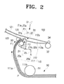
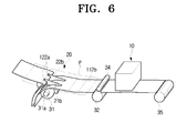
- the multi-passing apparatus 100 of Figure 1 is also illustrated in Figures 2, 3, 5, and 6.
- the multi-passing apparatus 100 includes a feeding passageway 110, at least one divergent passageway 120, and a guide unit 20.
- the feeding passageway 110 is disposed to feed the recording medium P from the feeding unit 50 to the image forming unit 10.
- the divergent passageway 120 diverges from a downstream portion of the feeding passageway 110.
- the guide unit 20 arranges a front end P1 (see Figure 2) of the recording medium P transferred through the feeding passageway 110 and guides the recording medium P, which has been first transferred to the image forming unit 10, toward the divergent passageway 120.
- the feeding passageway 110 extends from the feeding unit 50 to the image forming unit 10, and the recording medium P is picked up by the feeding roller 51 of the feeding unit 50 and then guided to the image forming unit 10 through the feeding passageway 110.
- the first and second transferring rollers 31 and 32 are installed on the feeding passageway 110.
- the feeding passageway 110 includes first and second feeding passageway 111 and 112.
- the first feeding passageway 111 extends from the feeding unit 50 to the first transferring roller 31, and the second feeding passageway 112 extends from the first transferring roller 31 to the image forming unit 10. Access to the first and second feeding passageways 111 and 112 by the recording medium P is controlled by the guide unit 20.
- the first feeding passageway 111 includes front and rear guide surfaces 111 a and 111b forming a space through which the recording medium P is transferred.
- the second feeding passageway 112 includes upper and lower guide surfaces 112a and 112b forming a space through which the recording medium P is transferred.
- the divergent passageway 120 guides the recording medium P so that the recording medium P is repeatedly transferred to the image forming unit 10.
- the divergent passageway 120 may be installed so that the recording medium P is unfolded and then repeatedly transferred. In other words, the divergent passageway 120 intersects with the second feeding passageway 112.
- the divergent passageway 120 includes upper and lower guide surfaces 121 and 122 forming a space through which the recording medium P is transferred.
- the guide unit 20 is installed to move between first and second positions S1 and S2 respectively illustrated in Figures 2 and 3.
- the guide unit 20 moves to the first position S1 so as to feed the recording medium P to the image forming device 10 and arrange the recording medium P.
- the guide unit 20 moves to the second position S2 so as to repeatedly transfer the recording medium P to the image forming unit 10.
- the guide unit 20 includes one or more guide members. As illustrated in FIGS 2-6, the guide unit 20 may include guide members 21 and 22. The guide members 21 and 22 pivot at an intersecting point between the feeding passageway 110 and the divergent passageway 120 in a direction F2 opposite to a direction F1 in which the recording medium P is fed as illustrated in Figure 2.
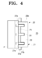
- the guide unit 20 may include a pair of guide members 21 and 22 which are connected to each other and pivot together by a bracket 23 as illustrated in Figure 4.
- the guide members 21 and 22 may pivot by a recovery force of an elastic member 25 along the direction F2 opposite to the direction F1 along which the recording medium P is fed.
- the elastic member 25 may be a coil spring, a torsion spring, a plate spring or the like.
- the elastic member 25 may include a first end 25a fixed to ends of the guide members 21 and 22 and a second end 25b fixed to a body of the image forming apparatus 200.
- the elastic member 25 elastically urges the guide members 21 and 22 to pivot along the direction F2 opposite to the direction F1 along which the recording medium P is fed.
- the guide members 21 and 22 may be pivotably supported on a rotary shaft 31 a of the first transferring roller 31 and pivot on the rotary shaft 31 a of the first transferring roller 31 by the recovery force of the elastic member 25.
- the guide members 21 and 22 respectively include arrangement surfaces 21a and 22a on their sides and guide surfaces 21b and 22b on other sides, as illustrated in Figures 2-6.
- the guide members 21 and 22 pivot in the direction F1 by a transfer force from the driven recording medium P, so as to move to the first position S1 connecting the first and second feeding passageways 111 and 112.
- the guide members 21 and 22 are pivoted in the direction F2 of Figure 2 by the elastic member 25.
- the guide members 21 and 22 uniformly press on the front end P1 of the recording medium P at spaced locations across the width direction due to the pivot force produced by the elastic member 25, as illustrated in Figure 4 to arrange the front end P1 of the recording medium P to an alignment position, in other words, so as to align the recoding medium in parallel with the passageway into the image forming unit 10 and thereby correct the aforementioned skewing.
- the recording medium P can then be repeatedly transferred back and forth to the image forming unit 10 in directions R1 and R2 indicated by arrows in Figure 3 by means of the second transferring roller 32, and so the image forming unit 10 can form an image on the recording medium P and prevent the occurrence of non-printed areas.
- the guide members 21 and 22 moved to the second position S2 close the connection between the first and second feeding passageways 111 and 112 to block the entrance of the recording medium P into the first feeding passageway 111.
- insertion grooves 122a may be formed in the lower guide surface 122 of the divergent passageway 120 adjacent to front ends of the guide members 21 and 22.
- the guide members 21 and 22 are inserted into the insertion grooves 122a.
- the divergent passageway 120 and the second feeding passageway 112 may form a further gentle guide surface.
- the recording medium P can be guided along an image forming passage repeatedly, and the recording medium P is well aligned with respect to a feeding direction so that it is not skewed when fed to the image forming unit.
Landscapes
- Physics & Mathematics (AREA)
- General Physics & Mathematics (AREA)
- Engineering & Computer Science (AREA)
- Mechanical Engineering (AREA)
- Feeding Of Articles By Means Other Than Belts Or Rollers (AREA)
- Photographic Developing Apparatuses (AREA)
Applications Claiming Priority (1)
| Application Number | Priority Date | Filing Date | Title |
|---|---|---|---|
| KR1020060055544A KR101244680B1 (ko) | 2006-06-20 | 2006-06-20 | 멀티 패싱장치 및 이를 포함하는 화상형성장치 |
Publications (2)
| Publication Number | Publication Date |
|---|---|
| EP1870779A2 true EP1870779A2 (de) | 2007-12-26 |
| EP1870779A3 EP1870779A3 (de) | 2010-09-22 |
Family
ID=38512575
Family Applications (1)
| Application Number | Title | Priority Date | Filing Date |
|---|---|---|---|
| EP20070104658 Withdrawn EP1870779A3 (de) | 2006-06-20 | 2007-03-22 | Mehrfachdurchführungsvorrichtung und damit ausgerüstete Bilderzeugungsvorrichtung |
Country Status (4)
| Country | Link |
|---|---|
| US (1) | US20070292189A1 (de) |
| EP (1) | EP1870779A3 (de) |
| KR (1) | KR101244680B1 (de) |
| CN (1) | CN101093369A (de) |
Cited By (1)
| Publication number | Priority date | Publication date | Assignee | Title |
|---|---|---|---|---|
| EP2399852A3 (de) * | 2010-06-28 | 2014-08-20 | Ricoh Company, Ltd. | Blattfördereinheit |
Families Citing this family (4)
| Publication number | Priority date | Publication date | Assignee | Title |
|---|---|---|---|---|
| JP2010241519A (ja) * | 2009-04-01 | 2010-10-28 | Kyocera Mita Corp | 用紙反転装置および画像形成装置 |
| EP3170777B1 (de) * | 2009-10-20 | 2018-12-12 | Canon Kabushiki Kaisha | Blattvorschubvorrichtung und bilderzeugungseinrichtung |
| US10048480B2 (en) * | 2011-01-07 | 2018-08-14 | Zeta Instruments, Inc. | 3D microscope including insertable components to provide multiple imaging and measurement capabilities |
| JP6107713B2 (ja) * | 2014-03-14 | 2017-04-05 | ブラザー工業株式会社 | 画像記録装置 |
Citations (6)
| Publication number | Priority date | Publication date | Assignee | Title |
|---|---|---|---|---|
| US5000598A (en) * | 1988-09-16 | 1991-03-19 | Ncr Corporation | Guide mechanism for dot matrix printer |
| US6374077B1 (en) * | 1997-10-17 | 2002-04-16 | Canon Kabushiki Kaisha | Sheet processing apparatus and image forming apparatus having this |
| US20020051665A1 (en) | 2000-10-26 | 2002-05-02 | Takashi Seto | Image formation apparatus, printer, copying machine, and facsimile device |
| US20030175060A1 (en) * | 2002-03-13 | 2003-09-18 | Canon Kabushiki Kaisha | Sheet guide device and image forming apparatus |
| US6727933B2 (en) * | 2002-09-12 | 2004-04-27 | Eastman Kodak Company | Preventing crease formation in donor web in dye transfer printer that can cause line artifact on print |
| JP2005021480A (ja) | 2003-07-04 | 2005-01-27 | Kao Corp | 棒状化粧料収納容器用中皿 |
Family Cites Families (17)
| Publication number | Priority date | Publication date | Assignee | Title |
|---|---|---|---|---|
| JPH0732066Y2 (ja) * | 1989-03-10 | 1995-07-26 | シチズン時計株式会社 | プリンタの用紙ガイド機構 |
| JPH03152041A (ja) * | 1989-11-09 | 1991-06-28 | Fuji Xerox Co Ltd | 画像形成装置 |
| US5427462A (en) * | 1991-04-16 | 1995-06-27 | Hewlett-Packard Company | Method and apparatus for paper control and skew correction in a printer |
| JPH06191705A (ja) * | 1992-12-28 | 1994-07-12 | Ricoh Co Ltd | 画像形成装置 |
| JPH07146593A (ja) * | 1993-11-25 | 1995-06-06 | Ricoh Co Ltd | 画像形成装置の両面ユニット |
| JPH0986726A (ja) * | 1995-09-21 | 1997-03-31 | Nec Corp | 用紙搬送位置補正装置 |
| JPH10218455A (ja) * | 1997-02-11 | 1998-08-18 | Ricoh Co Ltd | 用紙反転装置 |
| KR19990031187U (ko) * | 1997-12-30 | 1999-07-26 | 유기범 | 이송경로 변환장치 |
| JP4174186B2 (ja) * | 2000-02-25 | 2008-10-29 | 株式会社リコー | 画像形成装置 |
| JP2002154751A (ja) * | 2000-11-17 | 2002-05-28 | Toshiba Tec Corp | 画像形成装置 |
| US6782236B2 (en) * | 2001-10-02 | 2004-08-24 | Canon Kabushiki Kaisha | Duplex image forming apparatus |
| JP3740432B2 (ja) * | 2002-04-16 | 2006-02-01 | キヤノン株式会社 | 案内路交差部分のシート案内装置及び該装置を備えた画像形成装置 |
| JP4260059B2 (ja) * | 2004-05-11 | 2009-04-30 | 株式会社リコー | 画像形成装置 |
| KR20060030578A (ko) * | 2004-10-06 | 2006-04-11 | 삼성전자주식회사 | 양면 인쇄장치 |
| US7515866B2 (en) * | 2004-12-14 | 2009-04-07 | Ricoh Company, Ltd. | Image forming apparatus |
| US7467790B2 (en) * | 2005-03-24 | 2008-12-23 | Lexmark International, Inc. | Paper feed assembly |
| US7986912B2 (en) * | 2006-09-04 | 2011-07-26 | Konica Minolta Business Technologies, Inc. | Sheet conveyance apparatus and image forming apparatus with rollers to correct sheet misalignment |
-
2006
- 2006-06-20 KR KR1020060055544A patent/KR101244680B1/ko not_active Expired - Fee Related
- 2006-12-05 US US11/633,539 patent/US20070292189A1/en not_active Abandoned
-
2007
- 2007-03-22 EP EP20070104658 patent/EP1870779A3/de not_active Withdrawn
- 2007-04-10 CN CNA2007100960025A patent/CN101093369A/zh active Pending
Patent Citations (6)
| Publication number | Priority date | Publication date | Assignee | Title |
|---|---|---|---|---|
| US5000598A (en) * | 1988-09-16 | 1991-03-19 | Ncr Corporation | Guide mechanism for dot matrix printer |
| US6374077B1 (en) * | 1997-10-17 | 2002-04-16 | Canon Kabushiki Kaisha | Sheet processing apparatus and image forming apparatus having this |
| US20020051665A1 (en) | 2000-10-26 | 2002-05-02 | Takashi Seto | Image formation apparatus, printer, copying machine, and facsimile device |
| US20030175060A1 (en) * | 2002-03-13 | 2003-09-18 | Canon Kabushiki Kaisha | Sheet guide device and image forming apparatus |
| US6727933B2 (en) * | 2002-09-12 | 2004-04-27 | Eastman Kodak Company | Preventing crease formation in donor web in dye transfer printer that can cause line artifact on print |
| JP2005021480A (ja) | 2003-07-04 | 2005-01-27 | Kao Corp | 棒状化粧料収納容器用中皿 |
Cited By (1)
| Publication number | Priority date | Publication date | Assignee | Title |
|---|---|---|---|---|
| EP2399852A3 (de) * | 2010-06-28 | 2014-08-20 | Ricoh Company, Ltd. | Blattfördereinheit |
Also Published As
| Publication number | Publication date |
|---|---|
| EP1870779A3 (de) | 2010-09-22 |
| CN101093369A (zh) | 2007-12-26 |
| US20070292189A1 (en) | 2007-12-20 |
| KR20070120801A (ko) | 2007-12-26 |
| KR101244680B1 (ko) | 2013-03-18 |
Similar Documents
| Publication | Publication Date | Title |
|---|---|---|
| US7637499B2 (en) | Sheet feeding apparatus and recording apparatus | |
| KR101573944B1 (ko) | 연속적인 웹 운송 시스템 | |
| EP1870779A2 (de) | Mehrfachdurchführungsvorrichtung und damit ausgerüstete Bilderzeugungsvorrichtung | |
| JP4005644B2 (ja) | サーマルプリンタとその使用方法 | |
| CN100379572C (zh) | 媒体输送装置 | |
| CN100581959C (zh) | 对齐装置和具有该对齐装置的成像设备 | |
| KR100485782B1 (ko) | 화상형성장치의 용지배출장치 | |
| US8899722B2 (en) | Wiping assembly for a fluid ejection device | |
| CN101503153B (zh) | 片材输送机构及打印机 | |
| EP1634714B1 (de) | Verfahren zum Bedrucken eines Substrates und ein Tintenstrahldrucker geeignet dafür | |
| CA1265087A (en) | Single station, dual function printer | |
| US6840514B1 (en) | Media alignment mechanism | |
| US10662011B2 (en) | Media transport | |
| EP1634715A1 (de) | Drucker | |
| US10576755B2 (en) | Double-sided printer for printing receipts on thermal paper | |
| JP2002145484A (ja) | 媒体搬送装置の幅寄せ機構 | |
| KR200362494Y1 (ko) | 프린터의 급지장치 | |
| JP7532995B2 (ja) | 塗布装置、及び、画像形成システム | |
| JP4818146B2 (ja) | シート搬送装置及び記録装置 | |
| KR200143410Y1 (ko) | 잉크-젯 프린터의 급지장치 | |
| JP4864533B2 (ja) | 印字装置 | |
| JP6537370B2 (ja) | 媒体載置装置及び画像形成装置 | |
| JP2001180059A (ja) | 印字装置 | |
| JP2014080254A (ja) | シート収納装置及びこれを用いた画像形成システム | |
| JP2007175936A (ja) | インクジェット記録装置 |
Legal Events
| Date | Code | Title | Description |
|---|---|---|---|
| PUAI | Public reference made under article 153(3) epc to a published international application that has entered the european phase |
Free format text: ORIGINAL CODE: 0009012 |
|
| AK | Designated contracting states |
Kind code of ref document: A2 Designated state(s): AT BE BG CH CY CZ DE DK EE ES FI FR GB GR HU IE IS IT LI LT LU LV MC MT NL PL PT RO SE SI SK TR |
|
| AX | Request for extension of the european patent |
Extension state: AL BA HR MK YU |
|
| PUAL | Search report despatched |
Free format text: ORIGINAL CODE: 0009013 |
|
| AK | Designated contracting states |
Kind code of ref document: A3 Designated state(s): AT BE BG CH CY CZ DE DK EE ES FI FR GB GR HU IE IS IT LI LT LU LV MC MT NL PL PT RO SE SI SK TR |
|
| AX | Request for extension of the european patent |
Extension state: AL BA HR MK RS |
|
| RIC1 | Information provided on ipc code assigned before grant |
Ipc: B65H 9/00 20060101ALI20100817BHEP Ipc: G03G 15/00 20060101AFI20070926BHEP |
|
| 17P | Request for examination filed |
Effective date: 20110228 |
|
| AKX | Designation fees paid |
Designated state(s): DE FR GB NL |
|
| 17Q | First examination report despatched |
Effective date: 20120112 |
|
| RAP1 | Party data changed (applicant data changed or rights of an application transferred) |
Owner name: SAMSUNG ELECTRONICS CO., LTD. |
|
| STAA | Information on the status of an ep patent application or granted ep patent |
Free format text: STATUS: THE APPLICATION IS DEEMED TO BE WITHDRAWN |
|
| 18D | Application deemed to be withdrawn |
Effective date: 20150901 |