EP1869397B1 - Präziser längenstandard für einen kohärenten laserradar - Google Patents
Präziser längenstandard für einen kohärenten laserradar Download PDFInfo
- Publication number
- EP1869397B1 EP1869397B1 EP06738602.9A EP06738602A EP1869397B1 EP 1869397 B1 EP1869397 B1 EP 1869397B1 EP 06738602 A EP06738602 A EP 06738602A EP 1869397 B1 EP1869397 B1 EP 1869397B1
- Authority
- EP
- European Patent Office
- Prior art keywords
- fiber
- optical
- radiation
- outgassing
- measurement system
- Prior art date
- Legal status (The legal status is an assumption and is not a legal conclusion. Google has not performed a legal analysis and makes no representation as to the accuracy of the status listed.)
- Revoked
Links
- 230000001427 coherent effect Effects 0.000 title description 7
- 239000000835 fiber Substances 0.000 claims description 84
- 239000004642 Polyimide Substances 0.000 claims description 36
- 229920001721 polyimide Polymers 0.000 claims description 36
- 238000005259 measurement Methods 0.000 claims description 35
- 238000000576 coating method Methods 0.000 claims description 31
- 239000013307 optical fiber Substances 0.000 claims description 25
- 239000011248 coating agent Substances 0.000 claims description 21
- 238000010943 off-gassing Methods 0.000 claims description 21
- NIXOWILDQLNWCW-UHFFFAOYSA-M Acrylate Chemical compound [O-]C(=O)C=C NIXOWILDQLNWCW-UHFFFAOYSA-M 0.000 claims description 20
- 230000003287 optical effect Effects 0.000 claims description 19
- 230000005855 radiation Effects 0.000 claims description 18
- 238000000034 method Methods 0.000 claims description 13
- 238000010521 absorption reaction Methods 0.000 claims description 11
- 230000002209 hydrophobic effect Effects 0.000 claims description 10
- 239000000126 substance Substances 0.000 claims description 10
- 239000004677 Nylon Substances 0.000 claims description 2
- 239000004809 Teflon Substances 0.000 claims description 2
- 229920006362 Teflon® Polymers 0.000 claims description 2
- 229920006355 Tefzel Polymers 0.000 claims description 2
- QHSJIZLJUFMIFP-UHFFFAOYSA-N ethene;1,1,2,2-tetrafluoroethene Chemical group C=C.FC(F)=C(F)F QHSJIZLJUFMIFP-UHFFFAOYSA-N 0.000 claims description 2
- 229920001778 nylon Polymers 0.000 claims description 2
- 230000008859 change Effects 0.000 description 21
- 239000006094 Zerodur Substances 0.000 description 20
- 238000012360 testing method Methods 0.000 description 19
- 239000000463 material Substances 0.000 description 11
- 230000007613 environmental effect Effects 0.000 description 9
- 239000002184 metal Substances 0.000 description 8
- XLYOFNOQVPJJNP-UHFFFAOYSA-N water Chemical compound O XLYOFNOQVPJJNP-UHFFFAOYSA-N 0.000 description 8
- 239000012535 impurity Substances 0.000 description 6
- 230000010287 polarization Effects 0.000 description 6
- QAOWNCQODCNURD-UHFFFAOYSA-N Sulfuric acid Chemical compound OS(O)(=O)=O QAOWNCQODCNURD-UHFFFAOYSA-N 0.000 description 4
- 230000006872 improvement Effects 0.000 description 4
- YMWUJEATGCHHMB-UHFFFAOYSA-N Dichloromethane Chemical compound ClCCl YMWUJEATGCHHMB-UHFFFAOYSA-N 0.000 description 3
- 230000008901 benefit Effects 0.000 description 3
- 230000000694 effects Effects 0.000 description 3
- 238000005516 engineering process Methods 0.000 description 3
- 239000011521 glass Substances 0.000 description 3
- 239000003365 glass fiber Substances 0.000 description 3
- 238000004519 manufacturing process Methods 0.000 description 3
- 230000035559 beat frequency Effects 0.000 description 2
- 230000009977 dual effect Effects 0.000 description 2
- 230000007774 longterm Effects 0.000 description 2
- 238000002844 melting Methods 0.000 description 2
- 230000008018 melting Effects 0.000 description 2
- 238000012986 modification Methods 0.000 description 2
- 230000004048 modification Effects 0.000 description 2
- 229920000642 polymer Polymers 0.000 description 2
- 230000035945 sensitivity Effects 0.000 description 2
- 230000001954 sterilising effect Effects 0.000 description 2
- 238000004659 sterilization and disinfection Methods 0.000 description 2
- 239000004753 textile Substances 0.000 description 2
- 238000012795 verification Methods 0.000 description 2
- 150000001252 acrylic acid derivatives Chemical class 0.000 description 1
- 230000002411 adverse Effects 0.000 description 1
- 238000004458 analytical method Methods 0.000 description 1
- 238000004364 calculation method Methods 0.000 description 1
- 239000002131 composite material Substances 0.000 description 1
- 230000001010 compromised effect Effects 0.000 description 1
- 238000011109 contamination Methods 0.000 description 1
- 238000012937 correction Methods 0.000 description 1
- 239000013078 crystal Substances 0.000 description 1
- 230000001419 dependent effect Effects 0.000 description 1
- 230000009970 fire resistant effect Effects 0.000 description 1
- 239000002241 glass-ceramic Substances 0.000 description 1
- 238000002347 injection Methods 0.000 description 1
- 239000007924 injection Substances 0.000 description 1
- 238000011835 investigation Methods 0.000 description 1
- 238000012423 maintenance Methods 0.000 description 1
- 239000012528 membrane Substances 0.000 description 1
- 238000012544 monitoring process Methods 0.000 description 1
- 238000012545 processing Methods 0.000 description 1
- 230000000644 propagated effect Effects 0.000 description 1
- 239000010453 quartz Substances 0.000 description 1
- 238000002310 reflectometry Methods 0.000 description 1
- 230000035939 shock Effects 0.000 description 1
- VYPSYNLAJGMNEJ-UHFFFAOYSA-N silicon dioxide Inorganic materials O=[Si]=O VYPSYNLAJGMNEJ-UHFFFAOYSA-N 0.000 description 1
- 239000000758 substrate Substances 0.000 description 1
- 230000002277 temperature effect Effects 0.000 description 1
- 230000002123 temporal effect Effects 0.000 description 1
- 238000005382 thermal cycling Methods 0.000 description 1
- 238000012546 transfer Methods 0.000 description 1
Images


Classifications
-
- G—PHYSICS
- G01—MEASURING; TESTING
- G01B—MEASURING LENGTH, THICKNESS OR SIMILAR LINEAR DIMENSIONS; MEASURING ANGLES; MEASURING AREAS; MEASURING IRREGULARITIES OF SURFACES OR CONTOURS
- G01B9/00—Measuring instruments characterised by the use of optical techniques
- G01B9/02—Interferometers
- G01B9/02049—Interferometers characterised by particular mechanical design details
- G01B9/02052—Protecting, e.g. shock absorbing, arrangements
-
- G—PHYSICS
- G01—MEASURING; TESTING
- G01B—MEASURING LENGTH, THICKNESS OR SIMILAR LINEAR DIMENSIONS; MEASURING ANGLES; MEASURING AREAS; MEASURING IRREGULARITIES OF SURFACES OR CONTOURS
- G01B9/00—Measuring instruments characterised by the use of optical techniques
- G01B9/02—Interferometers
- G01B9/02001—Interferometers characterised by controlling or generating intrinsic radiation properties
- G01B9/02002—Interferometers characterised by controlling or generating intrinsic radiation properties using two or more frequencies
- G01B9/02004—Interferometers characterised by controlling or generating intrinsic radiation properties using two or more frequencies using frequency scans
-
- G—PHYSICS
- G01—MEASURING; TESTING
- G01B—MEASURING LENGTH, THICKNESS OR SIMILAR LINEAR DIMENSIONS; MEASURING ANGLES; MEASURING AREAS; MEASURING IRREGULARITIES OF SURFACES OR CONTOURS
- G01B9/00—Measuring instruments characterised by the use of optical techniques
- G01B9/02—Interferometers
- G01B9/02055—Reduction or prevention of errors; Testing; Calibration
- G01B9/0207—Error reduction by correction of the measurement signal based on independently determined error sources, e.g. using a reference interferometer
- G01B9/02072—Error reduction by correction of the measurement signal based on independently determined error sources, e.g. using a reference interferometer by calibration or testing of interferometer
-
- G—PHYSICS
- G01—MEASURING; TESTING
- G01B—MEASURING LENGTH, THICKNESS OR SIMILAR LINEAR DIMENSIONS; MEASURING ANGLES; MEASURING AREAS; MEASURING IRREGULARITIES OF SURFACES OR CONTOURS
- G01B2290/00—Aspects of interferometers not specifically covered by any group under G01B9/02
- G01B2290/60—Reference interferometer, i.e. additional interferometer not interacting with object
-
- G—PHYSICS
- G01—MEASURING; TESTING
- G01S—RADIO DIRECTION-FINDING; RADIO NAVIGATION; DETERMINING DISTANCE OR VELOCITY BY USE OF RADIO WAVES; LOCATING OR PRESENCE-DETECTING BY USE OF THE REFLECTION OR RERADIATION OF RADIO WAVES; ANALOGOUS ARRANGEMENTS USING OTHER WAVES
- G01S7/00—Details of systems according to groups G01S13/00, G01S15/00, G01S17/00
- G01S7/48—Details of systems according to groups G01S13/00, G01S15/00, G01S17/00 of systems according to group G01S17/00
- G01S7/497—Means for monitoring or calibrating
Definitions
- the present invention generally relates to Mach-Zehnder-configured interferometers and reference length standards in counter chirp FM laser radars. More specifically, methods and materials are described which alleviate interferometer drift due to vapor absorption observed for conventional fiber jacketing materials
- optical systems that can measure a distance to a target.
- Such systems typically utilize an open beam propagated through free space between the laser source and the target.
- the target location is such that limited free space is available for beam propagation, such systems are of limited use.
- well known systems may be able to perform distance measurements, but the open beam optical sensor head prevents application in limited access areas and tight places.
- precision measurement of dimensions inside a chassis cannot easily be accomplished with such open beam systems.
- precision is compromised due to the environmental effects on the fiber itself. These environmental effects can change the optical path length and the polarization of the light in the fiber, adversely affecting measurement precision.
- the existing art in length standards for these and related applications fall into two primary categories.
- One category involves an artifact based standard such as temperature compensated metal or glass bars/tubes with targets mounted to each end. For the range needed (2-4m) these are unwieldy and it is impractical to integrate them into a measurement system.
- the second category utilizes a fiber optic based length standard, which can easily be packaged into a small volume.
- the inventor herein has developed a counter chirp configuration that provides a much greater insensitivity to vibration induced range errors by providing for a more accurate Doppler correction.
- the fiber optic circuit is both less complicated and less expensive due to fewer components and completely immune to error caused by changes in the LO and signal path lengths due to environmental factors such as temperature.
- This configuration is described in U. S. Patent Specification No. US-A-2006/182393 the contents of which are incorporated herein' by reference as though set forth in their entirety. That technology utilized reference standards either of the Mach-Zehnder type or of the Michelson type. However, that application did not disclose methods of preventing non-temperature-related drift.
- Ahmadvand et al. U.S. Patent No. 6,778,278 disclose a method to compensate for temperature drift in a Mach-Zehnder interferometer by adding jacketing material of a specific thickness and length to one or both arms of the interferometer as a means of eliminating the need for active temperature control of the device. The result is that the two arms change the same amount with temperature changes despite the fact that they are different lengths. However, for higher channel density applications differences in path length will increase (as would the need for the temperature compensation). Moreover, they do not address other environmental causes of interferometer drift.
- the Mach-Zehnder interferometer formed by two couplers and the fiber between them is kept in a temperature-controlled container to prevent the fiber lengths from changing. If the difference in fiber lengths is calibrated, the reference interferometer can serve as an absolute length standard for the laser radar system as well as provide a signal useful in the linearization of the laser waveform.
- FM lasers are largely immune to ambient light conditions and changes in surface reflectivity because FM laser radars rely only on beat frequency, which is not dependent upon signal amplitude, to calculate range. This enables the FM Coherent system to make reliable measurements with as little as one picowatt of returned laser energy. This corresponds to a nine order-of-magnitude dynamic range of sensitivity. However, these instruments are not immune to drift caused by other ambient conditions.
- Ambient conditions other than temperature can affect effective optical path lengths in several ways.
- the presence of water vapor in the surrounding air affects the optics.
- volatile components of the polymers especially acrylate
- An effective optical path length in an optical fiber can change either because of a change in the refractive index of the core of the fiber, potentially caused by absorption of impurities, or because of a physical change in diameter or length of the fiber brought about by ambient conditions. If a fiber's jacket absorbs, for example, water vapor or other impurities, the jacket's dimensions change, thus exerting compressive force on the underlying glass fiber. Conversely, outgassing of water vapor or other impurities diminishes compressive force on the glass fiber. The change in force causes both the diameter and length of the fiber to change by small amounts and possibly the index of refraction to change, causing a change in effective optical path length.
- a measurement system as specified in claim 1.
- a method for minimizing drift due to the absorption on or outgassing of the optical fiber coating in measurement of distance along an electromagnetic (EM) radiation measurement path as specified in claim 11.
- Acrylate is the principal heritage coating or jacketing material for optical fibers. It has been designed into flight grade optical fiber for optical cable since the 1980's.
- the advantages of the acrylate material is that it can be selected for strippability (for example, with methylene chloride) and is fairly soft, which makes the fiber more flexible.
- Its disadvantages are that acrylates tend to have low temperature ratings (usually around 85°C although some are available that are rated as high as 200°C) and it is a well known outgasser.
- the present invention makes use of specially coated polarization maintaining (PM) fiber to reduce the change in the length of the reference arm.
- the coating is polyimide.
- An example of polyimide coated fiber available commercially is to be found at http://fibercore.com/05hb-hbp.php, "HB-P Polarization Maintaining Fiber.”
- polyimide coating has been used primarily for high temperature performance, e.g., to withstand medical sterilization and high curing temperatures.
- What is most novel in the current invention is to use polyimide and other acceptable coatings to provide dimensional, optical path length, and birefringence stability in addition to high temperature performance.
- Fibers are available and have been jacketed with many polymer coatings including Ultraviolet Cured (UV-cured) Acrylate, Polyimide, Teflon, DuPont Tefzel, Hytrel and Nylon. After acrylate, polyimide is probably the most readily available off-the-shelf especially in PM fiber and works well for this application.
- metal coated fibers can provide dimensional stability but may have higher temperature sensitivities. Fibers that function in the way described in this disclosure are referred to herein as substantially hydrophobic and substantially non-outgassing.
- Polyimide has been used successfully for coating space grade optical fiber and it comes with the advantage of a 125°C temperature rating. However, it was not an obvious choice for use in a laser metrology device because of its known disadvantages. Polyimide has exhibited some disadvantages that have made it a less than desirable first choice for coating optical fibers. For example, polyimide tends to make the fiber seem stiffer than an acrylate coated fiber. Second coatings have been added, but the known additional coatings come with their own problems that have limited the desirability of polyimide for mainstream applications. For example, such second coatings have exhibited outgassing and contamination problems. Of even more significance are the difficulties associated with stripping polyimide.
- Polyimide coating can be stripped chemically, with hot sulfuric acid, or mechanically, using a hot tweezers. Users find hot sulfuric acid to be dangerous and non-portable. Mechanical stripping methods are not recommended because they have the capacity to introduce surface flaws to the glass fiber, compromising long term reliability. As noted elsewhere, the realization that it offered superior vapor absorption and outgassing properties that provided improved dimensional stability led to its adoption for the current invention.
- the coherent laser radar as it is currently envisaged requires a fiber optic reference arm interferometer in a Mach-Zehnder configuration as its reference length standard.
- This internal length standard is calibrated by using an external interferometer to determine the exact length differential between the two paths of the reference interferometer.
- this length difference varies with time there will be a corresponding scaling error in range measurements on the measurement path.
- the present invention diminishes the length variation within the reference arm, allowing for long-term range accuracy without the need for frequent calibration.
- the present invention is applicable to all non-contact precision distance measuring applications that incorporate a fiber optic length standard.
- the insensitivity of the polyimide coating to environmental conditions allows a system to operate for months in a changing environment and remain within specification without the need for a range calibration, effectively reducing the necessary system maintenance and extending the time between scheduled certification.
- Figure 1 shows the reference arm
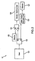
- Figure 2 shows a metal coated fiber test setup.
- Figure 3 shows a dual Zerodur test setup.
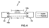
- Figure 4 shows a prototype polyimide reference arm.
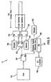
- Figure 5 show a polyimide coated reference arm with dual Zerodur LOs.
- coherent radiation means radiation in which the phase relationship between any two points in the radiation field has a constant difference, or is exactly the same in either the spatial or the temporal mode throughout the duration of the radiation.
- a laser is a device which artificially generates coherent radiation in the form of light within a narrow range of wavelengths.
- Advanced techniques employed in the invention set forth in U. S. Patent Specification No US-A-2006/182383 enable a high degree of linearity in the relative distance measurements.
- these techniques can detect and compensate for real time variances from linearity.
- These features enable range measurement with a single digit micron precision. Such precision is high enough that preventing drift caused by environmental factors becomes extremely important.
- this reference standard can take the form of a fiber optic interferometer in a Mach-Zehnder configuration, 10, Figure 1 .
- the light from an IR laser, 101 after passing through an isolator (not shown), is split into two fibers by means of a fiber coupler, 102. One path is used to measure range, 103.
- the other path is directed to the reference standard that consists of an input fiber optic coupler, RC1, 104, which splits the light into two fiber paths (105a, 105b) and an output fiber coupler, RC2,106, which recombines the light into a single fiber.
- the two paths of fiber between the two couplers are mismatched in length by several meters such that a laser radar signal is detected on the detector, R1 107.
- the Mach-Zehnder interferometer formed by the two couples and the fiber between them is kept in a temperature-controlled container to prevent the fiber lengths from changing.
- the reference interferometer can serve as an absolute length standard for the laser radar system as well as provide a signal useful in the linearization of the laser waveform.
- the single mode, polarization maintaining fiber widely available uses a UV cured acrylate coating that is hygroscopic. This coating tends to absorb or outgas water vapor and other impurities causing an effective change in the optical length of the reference arm. In many cases, this drift can be severer and rapid, resulting in a change of several hundred microns (10-100 parts per million (PPM)) in a matter of hours/days. Unlike drift in one of the LO paths which simply translates into a range offset, this change in the reference arm length has a direct effect on the range accuracy of the machine, i.e., an increase in reference arm length of 1 part per million results in an across the board range error of 1 part per million.
- This application discloses use of specially coated PM fiber to reduce the change in the optical path lengths in the reference arm.
- polyimides have numerous uses in several fields, as a fiber optic coating it offers a reduced cross sectional area (low profile) that would also be heat resistant for high temperature applications such as medical sterilization and high curing temperatures of various laminates. It is also used for increased protection in hostile environments.
- the current application makes use of its water resistant nature (typically used only in textiles; see, e.g., Hope, Diane, "New Technologies for Fire Resistant Textiles and Membranes," Innovation, vol. 8, no. 5, September/October 2000 ) to eliminate the outgassing common in the acrylate coated fiber.
- the 50/50 fiber optic couplers are fitted with output fibers coated in polyimide.
- the reference arm When the reference arm is built, only fiber coated with polyimide is used, resulting in a reference arm whose drift will be minimized due to the absorption on or outgassing of the fiber jacket.
- the thin polyimide coating exhibits a marked improvement over the acrylate, resulting in an order of magnitude improvement over the old technology.
- the improved performance can be easily demonstrated by comparison with the calculation above.
- the reference path increases by 4 microns, or 1 PPM. This gives scaling factors of 0.575000 and 0.574999425 MHz/m.
- the drifted value is only 10 microns from the assumed value in comparison to 100 microns before, or an improvement of about a factor of 10 in precision over the conventionally coated fiber.
- MV200 TM i.e., portable coherent laser radar system sold under the Trademark MV200 TM
- MV200 TM portable coherent laser radar system sold under the Trademark MV200 TM
- a test setup was built in a temperature-controlled environment, 12, as shown in Figure 2 .
- the setup consisted of a current MV200 TM oven, 121, used as a laser source feeding into a test oven that contained a standard reference arm.
- the fiber within the oven was coated as thoroughly as possible with low melting point metal, 123.
- the signal generated by the test oven was measured by the detector.
- ZERODUR® a substance that exhibits minimal thermal expansion (+/-0.15 x 10 -6 /degree C).
- Many optical applications require a substrate material with a near-zero coefficient of thermal expansion and/or excellent thermal shock resistance.
- ZERODUR® with its very small coefficient of thermal expansion at room temperature, is such a material.
- ZERODUR which belongs to the glass-ceramic composite class of materials, has both an amorphous (vitreous) component and a crystalline component. This Schott glass is subjected to special thermal cycling during manufacture so that approximately 75% of the vitreous material is converted to the crystalline quartz form.
- the crystals are typically only 50 nm in diameter, and ZERODUR appears reasonably transparent to the eye because the refractive indices of the two phases are almost identical. However, scattering at the grain boundaries precludes the use of ZERODUR for transmissive optics.
- FIG. 1 shows the complete layout (12).
- the drift in the test oven was measured by comparing the range measurement at the test oven detector, 127, to the range measured at the monitor detector, 125.
- This setup was attached to standard MV200 TM signal processing electronics with scanner control flags disabled.
- the setup was powered on, linearized, and allowed to settle for about an hour. Data was collected over the course of a week by using the stare measurement dialog, and all data was corrected for range deviation due to environmental temperature and pressure changes.
- the setup from Figure 2 was altered such that the test oven was removed and a second zerodur path interferometer installed, 13, as shown in Figure 3 .
- One of these paths was used as a reference arm and the other was used as local oscillator one (LO1) and data was recorded over the course of a week.
- the light from the MV200 TM oven, 131 passes through a 50/50 optic coupler, 133, thereby splitting the beam into two fibers.
- the split beams are sent via the 70/30 couplers 135 and 136, to the open air path Michelson interferometers, 137, as described above.
- the output of each interferometer is measured by the detectors, 132 and 134. By monitoring the output of the detectors, the intrinsic drift of the zerodur paths can be measured.
- the light from the MV200 TM oven, 151 passes through a 90/10 optic coupler, 152 , splitting the beam into two fibers.
- a first fiber beam is passed through a 50/50 optic coupler, 153 , thereby splitting the first beam into two separate fibers which are sent, via the 70/30 couplers, 154 and 155 , to the open air path Michelson interferometers, 158 , as described above.
- the output of each interferometer is measured by the detectors, 156 and 157 .
- Table 1 Test results from initial coatings testing Metal Coated fiber vs. Zerodur Zerodur reference vs. Zerodur (Set 3) Polyimide fiber vs. Zerodur LO1 (Set 3) Polyimide fiber vs. Zerodur LO2 (Set 4) Polyimide fiber vs. Oven 6 reference (Set 4) Polyimide fiber. vs. Zerodur Range Spread in Microns 52.9 11.7 15.2 18.6 69.5 18 Range Spread in PPM 27.3 5.0 7.1 8.7 19 7.9
- the polyimide coated fiber performed substantially better than that coated with acrylate.
- the polyimide fiber performed almost as well as zerodur compared to zerodur, suggesting that the drift within the polyimide reference could possibly be attributed to drift within the relatively short acrylate leads or to inherent instability of the open air setup.
- couplers were produced with polyimide leads to ensure that the critical lengths (i.e., where the reference path was split) would exhibit maximum stability.
- These couplers were used to fabricate a reference arm in a standard MV200 TM oven and mounted in a system to be tested as a complete unit. This testing consisted of a standard Range Calibration and Verification followed by scanner performance testing under a variety of environmental conditions. The scanner was then subjected to another Range Verification. A second Range Calibration was performed if necessary.
Landscapes
- Physics & Mathematics (AREA)
- General Physics & Mathematics (AREA)
- Instruments For Measurement Of Length By Optical Means (AREA)
- Investigating Or Analysing Materials By Optical Means (AREA)
Claims (12)
- Messsystem, das Folgendes umfasst:ein optisches Messsystem zum Liefern von elektromagnetischer (EM) Strahlung zu einem Messpfad; ein optisches Bezugssystem, das zwei Lichtleitfasern (105a, 105b) umfasst; wobei eine Lichtleitfaser von den zwei Fasern eine Länge aufweist, die von der einer anderen Lichtleitfaser von den zwei Fasern verschieden ist; einen Detektor (107) zum Kalibrieren einer Längendifferenz zwischen den zwei Lichtleitfasern; und Berechnen der Strecke entlang dem Messpfad als Funktion der Längendifferenz;wobei das Messsystem dadurch gekennzeichnet ist, dass;jede Lichtleitfaser von den zwei Lichtleitfasern mit einer im Wesentlichen hydrophoben und im Wesentlichen nicht ausgasenden Substanz beschichtet ist, um Drift infolge der Absorption auf der oder dem Ausgasen von der Lichtleitfaserbeschichtung zu minimieren.
- Messsystem nach Anspruch 1, das weiter Folgendes umfasst:einen ersten Lichtleitfaserkoppler (102) zum Empfangen der EM-Strahlung; undAufteilen der EM-Strahlung in den Messpfad und den Bezugspfad; wobei der Bezugspfad einen zweiten Lichtleitfaserkoppler (104) zum Empfangen der EM-Strahlung für den Bezugspfad umfasst; und Aufteilen der zwei Lichtleitfasern;einen dritten Lichtleitfaserkoppler (106) zum Empfangen von EM-Strahlung von den zwei Lichtleitfasern; und Liefern der empfangenen EM-Strahlung zu einer einzelnen Faser; und den Detektor von der einzelnen Faser.
- Messsystem nach Anspruch 1, wobei es sich bei der im Wesentlichen hydrophoben und im Wesentlichen nicht ausgasenden Substanz um Polyimid handelt.
- Messsystem nach Anspruch 3, wobei Drift infolge der Absorption auf der oder dem Ausgasen von der Lichtleitfaserbeschichtung minimiert ist, so dass ein gedrifteter Wert von ungefähr 1 Teil pro Million (ppm) von einem angenommenen Wert erhalten wird.
- Messsystem nach Anspruch 1, wobei es sich bei der im Wesentlichen hydrophoben und im Wesentlichen nicht ausgasenden Substanz um mit Ultraviolettlicht ausgehärtetes Acrylat handelt.
- Messsystem nach Anspruch 1, wobei sich der Bezugspfad in einer Mach-Zehnder-Konfiguration befindet.
- Messsystem nach Anspruch 1, wobei es sich bei der im Wesentlichen hydrophoben und im Wesentlichen nicht ausgasenden Substanz um Teflon handelt.
- Messsystem nach Anspruch 1, wobei es sich bei der im Wesentlichen hydrophoben und im Wesentlichen nicht ausgasenden Substanz um Tefzel handelt.
- Messsystem nach Anspruch 1, wobei es sich bei der im Wesentlichen hydrophoben und im Wesentlichen nicht ausgasenden Substanz um Hytrel handelt.
- Messsystem nach Anspruch 1, wobei es sich bei der im Wesentlichen hydrophoben und im Wesentlichen nicht ausgasenden Substanz um Nylon handelt.
- Verfahren zum Minimieren von Drift infolge der Absorption auf der oder dem Ausgasen von der Lichtleitfaserbeschichtung bei der Streckenmessung entlang einem elektromagnetische (EM) Strahlung nutzenden Messpfad, wobei das Verfahren folgende Schritte umfasst:Empfangen von EM-Bezugsstrahlung in einen ersten Lichtleitfaserkoppler;Aufteilen, durch den ersten Lichtleitfaserkoppler, der empfangenen EM-Bezugsstrahlung in zwei Lichtleitfasern; Kombinieren, durch einen zweiten Lichtleitfaserkoppler, von den zwei Lichtleitfasern empfangener EM-Strahlung undLiefern der kombinierten EM-Strahlung zu einer einzigen Lichtleitfaser; undKalibrieren, aus der kombinierten EM-Strahlung, einer Längendifferenz zwischen den zwei Lichtleitfasern; wobei das Verfahren gekennzeichnet ist, durch:Beschichten der zwei Lichtleitfasern mit einer im Wesentlichen hydrophoben und im Wesentlichen nicht ausgasenden Substanz.
- Verfahren nach Anspruch 11, wobei durch Nutzen der zwei mit Polyimid als die im Wesentlichen hydrophobe und im Wesentlichen nicht ausgasende Substanz beschichteten Lichtleitfasern Drift infolge der Absorption auf oder dem Ausgasen von der Lichtleitfaserbeschichtung minimiert ist, so dass ein gedrifteter Wert von ungefähr 1 Teil pro Million (ppm) von einem angenommenen Wert erhalten wird.
Applications Claiming Priority (3)
| Application Number | Priority Date | Filing Date | Title |
|---|---|---|---|
| US66236705P | 2005-03-17 | 2005-03-17 | |
| US11/376,351 US20060280415A1 (en) | 2005-03-17 | 2006-03-15 | Precision length standard for coherent laser radar |
| PCT/US2006/009564 WO2006102001A2 (en) | 2005-03-17 | 2006-03-16 | Precision length standard for coherent laser radar |
Publications (3)
| Publication Number | Publication Date |
|---|---|
| EP1869397A2 EP1869397A2 (de) | 2007-12-26 |
| EP1869397A4 EP1869397A4 (de) | 2012-04-04 |
| EP1869397B1 true EP1869397B1 (de) | 2013-05-22 |
Family
ID=37024394
Family Applications (1)
| Application Number | Title | Priority Date | Filing Date |
|---|---|---|---|
| EP06738602.9A Revoked EP1869397B1 (de) | 2005-03-17 | 2006-03-16 | Präziser längenstandard für einen kohärenten laserradar |
Country Status (3)
| Country | Link |
|---|---|
| US (2) | US20060280415A1 (de) |
| EP (1) | EP1869397B1 (de) |
| WO (1) | WO2006102001A2 (de) |
Cited By (3)
| Publication number | Priority date | Publication date | Assignee | Title |
|---|---|---|---|---|
| EP3032277A1 (de) | 2014-12-12 | 2016-06-15 | Leica Geosystems AG | Lasertracker |
| EP3165876A2 (de) | 2015-11-03 | 2017-05-10 | Hexagon Technology Center GmbH | Opto-elektronisches vermessungsgerät |
| EP3220163A1 (de) | 2016-03-15 | 2017-09-20 | Leica Geosystems AG | Lasertracker mit zwei messfunktionalitäten |
Families Citing this family (10)
| Publication number | Priority date | Publication date | Assignee | Title |
|---|---|---|---|---|
| US20060280415A1 (en) | 2005-03-17 | 2006-12-14 | Anthony Slotwinski | Precision length standard for coherent laser radar |
| JP2013545976A (ja) | 2010-10-25 | 2013-12-26 | 株式会社ニコン | 装置、光学アセンブリ、物体を検査又は測定する方法、及び構造体を製造する方法 |
| US8724095B2 (en) | 2011-10-25 | 2014-05-13 | Nikon Corporation | Optical assembly for laser radar |
| US8937725B2 (en) | 2012-06-14 | 2015-01-20 | Nikon Corporation | Measurement assembly including a metrology system and a pointer that directs the metrology system |
| US20140082775A1 (en) * | 2012-09-18 | 2014-03-20 | Brookhaven Science Associates, Llc | Modular UHV Compatible Angle Physical Contact Fiber Connection for Transferable Fiber Interferometer Type Dynamic Force Microscope Head |
| US10119816B2 (en) | 2012-11-21 | 2018-11-06 | Nikon Metrology Nv | Low drift reference for laser radar |
| US9638799B2 (en) | 2012-11-21 | 2017-05-02 | Nikon Corporation | Scan mirrors for laser radar |
| US10180496B2 (en) | 2012-11-21 | 2019-01-15 | Nikon Corporation | Laser radar with remote local oscillator |
| US10989879B2 (en) * | 2014-06-03 | 2021-04-27 | Nikon Metrology Nv | Thermally compensated fiber interferometer assembly |
| WO2020072484A1 (en) | 2018-10-01 | 2020-04-09 | Nikon Corporation | An auxiliary focus measurement for a laser radar 3d scanner |
Family Cites Families (35)
| Publication number | Priority date | Publication date | Assignee | Title |
|---|---|---|---|---|
| JPS57124308A (en) * | 1981-01-26 | 1982-08-03 | Furukawa Electric Co Ltd:The | Metal-coated glass fiber |
| US4427263A (en) * | 1981-04-23 | 1984-01-24 | The United States Of America As Represented By The Secretary Of The Navy | Pressure insensitive optical fiber |
| US4830486A (en) * | 1984-03-16 | 1989-05-16 | Goodwin Frank E | Frequency modulated lasar radar |
| GB2171514B (en) * | 1985-02-23 | 1988-03-09 | Stc Plc | Magnetic gradient detector and method |
| DE3767042D1 (de) * | 1986-06-16 | 1991-02-07 | Siemens Ag | Messvorrichtung zur intrakardialen erfassung der blutsauerstoffsaettigung. |
| US4824251A (en) * | 1987-09-25 | 1989-04-25 | Digital Signal Corporation | Optical position sensor using coherent detection and polarization preserving optical fiber |
| US5493627A (en) * | 1988-01-15 | 1996-02-20 | Sippican, Inc. | Waveguide pack |
| GB2214652B (en) * | 1988-01-21 | 1991-05-01 | Stc Plc | Ruggedised optical fibres |
| JPH0239112A (ja) * | 1988-07-29 | 1990-02-08 | Showa Electric Wire & Cable Co Ltd | 耐熱光ファイバケーブル |
| US4994668A (en) * | 1989-09-01 | 1991-02-19 | The United States Of America As Represented By The Secretary Of The Navy | Planar fiber-optic interferometric acoustic sensor |
| JP2825097B2 (ja) * | 1989-09-25 | 1998-11-18 | 日立電線株式会社 | 光ファイバの製造方法 |
| JPH0483209A (ja) * | 1990-07-26 | 1992-03-17 | Sumitomo Electric Ind Ltd | 被覆光ファイバ |
| JPH04156504A (ja) * | 1990-10-19 | 1992-05-29 | Hitachi Cable Ltd | 耐熱性光ファイバ |
| US5282466A (en) * | 1991-10-03 | 1994-02-01 | Medtronic, Inc. | System for disabling oximeter in presence of ambient light |
| US5402230A (en) * | 1991-12-16 | 1995-03-28 | Tsinghua University | Heterodyne interferometric optical fiber displacement sensor for measuring displacement of an object |
| US5428471A (en) * | 1992-07-30 | 1995-06-27 | Alcatel Network Systems, Inc. | Fail-safe automatic shut-down apparatus and method for high output power optical communications system |
| US5714196A (en) * | 1994-07-20 | 1998-02-03 | Galileo Corporation | Method of forming a strippable polyimide coating for an optical fiber |
| JPH08271770A (ja) * | 1995-03-31 | 1996-10-18 | Furukawa Electric Co Ltd:The | 耐熱光ファイバ心線 |
| US5771114A (en) * | 1995-09-29 | 1998-06-23 | Rosemount Inc. | Optical interface with safety shutdown |
| US6726684B1 (en) * | 1996-07-16 | 2004-04-27 | Arthrocare Corporation | Methods for electrosurgical spine surgery |
| US5945668A (en) * | 1997-06-20 | 1999-08-31 | Sun Microsystems, Inc. | Fiber optic system with open fiber safety interlock |
| JP3587971B2 (ja) * | 1997-09-26 | 2004-11-10 | 富士通株式会社 | 光通信ユニット |
| JPH11242143A (ja) * | 1998-02-25 | 1999-09-07 | Hitachi Ltd | 光ファイバ及びそれを用いた光センシングシステム |
| US6251688B1 (en) * | 1998-03-20 | 2001-06-26 | Ia, Inc. | Method and apparatus for measurement of binding between a protein and a nucleotide |
| US6317526B1 (en) * | 1998-12-21 | 2001-11-13 | Fujitsu Limited | Optical phase controller and optical switch |
| US6778278B2 (en) * | 2000-08-03 | 2004-08-17 | Peleton Photonic Systems Inc. | Temperature insensitive Mach-Zehnder interferometers and devices |
| US7277822B2 (en) * | 2000-09-28 | 2007-10-02 | Blemel Kenneth G | Embedded system for diagnostics and prognostics of conduits |
| US6988854B2 (en) * | 2001-12-14 | 2006-01-24 | Sanmina-Sci Corporation | Cable dispenser and method |
| US6757469B2 (en) * | 2002-03-18 | 2004-06-29 | Fraunhofer-Gesellschaft zur Förderung der angewandten Forschung e.V. | Temperature insensitive optical waveguide device |
| JP2003322774A (ja) * | 2002-05-07 | 2003-11-14 | Totoku Electric Co Ltd | メタライズドポリイミドコート光ファイバおよび光ファイバ付き光学装置 |
| US7215688B2 (en) * | 2003-01-17 | 2007-05-08 | Avago Technologies Fiber Ip (Singapore) Pte. Ltd. | Disable/enable control for laser driver eye safety |
| JP2004226169A (ja) * | 2003-01-21 | 2004-08-12 | Totoku Electric Co Ltd | 光ファイバコイル |
| JP4211034B2 (ja) * | 2003-11-27 | 2009-01-21 | 孝雄 津田 | インジェクター |
| US7139446B2 (en) | 2005-02-17 | 2006-11-21 | Metris Usa Inc. | Compact fiber optic geometry for a counter-chirp FMCW coherent laser radar |
| US20060280415A1 (en) | 2005-03-17 | 2006-12-14 | Anthony Slotwinski | Precision length standard for coherent laser radar |
-
2006
- 2006-03-15 US US11/376,351 patent/US20060280415A1/en not_active Abandoned
- 2006-03-16 EP EP06738602.9A patent/EP1869397B1/de not_active Revoked
- 2006-03-16 WO PCT/US2006/009564 patent/WO2006102001A2/en not_active Ceased
-
2008
- 2008-06-30 US US12/164,711 patent/US7925134B2/en active Active
Cited By (6)
| Publication number | Priority date | Publication date | Assignee | Title |
|---|---|---|---|---|
| EP3032277A1 (de) | 2014-12-12 | 2016-06-15 | Leica Geosystems AG | Lasertracker |
| US10725179B2 (en) | 2014-12-12 | 2020-07-28 | Leica Geosystems Ag | Laser tracker |
| EP3165876A2 (de) | 2015-11-03 | 2017-05-10 | Hexagon Technology Center GmbH | Opto-elektronisches vermessungsgerät |
| US11035935B2 (en) | 2015-11-03 | 2021-06-15 | Hexagon Technology Center Gmbh | Optoelectronic surveying device |
| EP3220163A1 (de) | 2016-03-15 | 2017-09-20 | Leica Geosystems AG | Lasertracker mit zwei messfunktionalitäten |
| US10444361B2 (en) | 2016-03-15 | 2019-10-15 | Leica Geosystems Ag | Laser tracker having two measurement functionalities |
Also Published As
| Publication number | Publication date |
|---|---|
| WO2006102001A2 (en) | 2006-09-28 |
| US20060280415A1 (en) | 2006-12-14 |
| EP1869397A2 (de) | 2007-12-26 |
| EP1869397A4 (de) | 2012-04-04 |
| US7925134B2 (en) | 2011-04-12 |
| US20090323077A1 (en) | 2009-12-31 |
| WO2006102001A3 (en) | 2007-12-06 |
Similar Documents
| Publication | Publication Date | Title |
|---|---|---|
| US7925134B2 (en) | Precision length standard for coherent laser radar | |
| Lu et al. | Temperature-strain discrimination in distributed optical fiber sensing using phase-sensitive optical time-domain reflectometry | |
| CN101253392B (zh) | 光纤温度和压力传感器和包括它们的系统 | |
| Kreuzer | Strain measurement with fiber Bragg grating sensors | |
| US5657405A (en) | Optical fiber sensor for measuring pressure or displacement | |
| Rao et al. | Novel fiber-optic sensors based on long-period fiber gratings written by high-frequency CO 2 laser pulses | |
| US10989879B2 (en) | Thermally compensated fiber interferometer assembly | |
| Korenko et al. | Novel fiber-optic relative humidity sensor with thermal compensation | |
| US11662250B2 (en) | Wavelength reference device | |
| JP2561861B2 (ja) | 組合わされたスケールと干渉計 | |
| Chu et al. | Optical voltage sensors based on integrated optical polarization-rotated reflection interferometry | |
| Neves et al. | Humidity-insensitive optical fibers for distributed sensing applications | |
| Perrot et al. | Radiation effects on Brillouin-based Sensors: Feasibility of temperature and strain discrimination using LEAF Single-Mode optical fiber | |
| CN102959374A (zh) | 光纤双折射温度计和用于制造其的方法 | |
| Dyer et al. | Key metrology considerations for fiber Bragg grating sensors | |
| Terra | Distance scale calibration of optical time domain reflectometer using active intensity modulation | |
| Lin et al. | Effects of gamma radiation on optical fibre sensors | |
| Wang et al. | Research on suppression of temperature effect of 260 m polarization multiplexing fiber interferometer | |
| KR102933720B1 (ko) | 흡수식 광섬유 기반 이중 광섬유필터 모듈을 이용한 광파장 측정 장치, 이를 구비한 광센서 시스템 및 광측정 방법 | |
| Courteville et al. | Positioning of optical payload: SALT Telescope | |
| Snyder et al. | Wavelength measurement with a Young’s interferometer | |
| GB2419401A (en) | Polarimetric differential optical fibre sensor | |
| Xiao | Self-calibrated interferometric/intensity based fiber optic pressure sensors | |
| US11920928B2 (en) | System and method for correcting optical path length measurement errors | |
| Schellekens et al. | Accuracy of commercially available laser measurement systems |
Legal Events
| Date | Code | Title | Description |
|---|---|---|---|
| PUAI | Public reference made under article 153(3) epc to a published international application that has entered the european phase |
Free format text: ORIGINAL CODE: 0009012 |
|
| AK | Designated contracting states |
Kind code of ref document: A2 Designated state(s): AT BE BG CH CY CZ DE DK EE ES FI FR GB GR HU IE IS IT LI LT LU LV MC NL PL PT RO SE SI SK TR |
|
| AX | Request for extension of the european patent |
Extension state: AL BA HR MK YU |
|
| R17D | Deferred search report published (corrected) |
Effective date: 20071206 |
|
| RIC1 | Information provided on ipc code assigned before grant |
Ipc: G02B 6/36 20060101AFI20071212BHEP |
|
| 17P | Request for examination filed |
Effective date: 20080109 |
|
| RBV | Designated contracting states (corrected) |
Designated state(s): AT BE BG CH CY CZ DE DK EE ES FI FR GB GR HU IE IS IT LI LT LU LV MC NL PL PT RO SE SI SK TR |
|
| DAX | Request for extension of the european patent (deleted) | ||
| RAP1 | Party data changed (applicant data changed or rights of an application transferred) |
Owner name: NIKON METROLOGY, INC. |
|
| RAP1 | Party data changed (applicant data changed or rights of an application transferred) |
Owner name: NIKON METROLOGY NV |
|
| REG | Reference to a national code |
Ref country code: DE Ref legal event code: R079 Ref document number: 602006036426 Country of ref document: DE Free format text: PREVIOUS MAIN CLASS: G01B0009020000 Ipc: G02B0006360000 |
|
| A4 | Supplementary search report drawn up and despatched |
Effective date: 20120305 |
|
| RIC1 | Information provided on ipc code assigned before grant |
Ipc: G02B 6/36 20060101AFI20120228BHEP |
|
| GRAP | Despatch of communication of intention to grant a patent |
Free format text: ORIGINAL CODE: EPIDOSNIGR1 |
|
| GRAS | Grant fee paid |
Free format text: ORIGINAL CODE: EPIDOSNIGR3 |
|
| GRAP | Despatch of communication of intention to grant a patent |
Free format text: ORIGINAL CODE: EPIDOSNIGR1 |
|
| GRAA | (expected) grant |
Free format text: ORIGINAL CODE: 0009210 |
|
| INTG | Intention to grant announced |
Effective date: 20130328 |
|
| AK | Designated contracting states |
Kind code of ref document: B1 Designated state(s): AT BE BG CH CY CZ DE DK EE ES FI FR GB GR HU IE IS IT LI LT LU LV MC NL PL PT RO SE SI SK TR |
|
| REG | Reference to a national code |
Ref country code: GB Ref legal event code: FG4D |
|
| REG | Reference to a national code |
Ref country code: CH Ref legal event code: EP |
|
| REG | Reference to a national code |
Ref country code: AT Ref legal event code: REF Ref document number: 613514 Country of ref document: AT Kind code of ref document: T Effective date: 20130615 |
|
| REG | Reference to a national code |
Ref country code: IE Ref legal event code: FG4D |
|
| REG | Reference to a national code |
Ref country code: CH Ref legal event code: NV Representative=s name: ARNOLD AND SIEDSMA AG, CH |
|
| REG | Reference to a national code |
Ref country code: DE Ref legal event code: R096 Ref document number: 602006036426 Country of ref document: DE Effective date: 20130718 |
|
| REG | Reference to a national code |
Ref country code: AT Ref legal event code: MK05 Ref document number: 613514 Country of ref document: AT Kind code of ref document: T Effective date: 20130522 |
|
| REG | Reference to a national code |
Ref country code: LT Ref legal event code: MG4D |
|
| PG25 | Lapsed in a contracting state [announced via postgrant information from national office to epo] |
Ref country code: LT Free format text: LAPSE BECAUSE OF FAILURE TO SUBMIT A TRANSLATION OF THE DESCRIPTION OR TO PAY THE FEE WITHIN THE PRESCRIBED TIME-LIMIT Effective date: 20130522 Ref country code: GR Free format text: LAPSE BECAUSE OF FAILURE TO SUBMIT A TRANSLATION OF THE DESCRIPTION OR TO PAY THE FEE WITHIN THE PRESCRIBED TIME-LIMIT Effective date: 20130823 Ref country code: SE Free format text: LAPSE BECAUSE OF FAILURE TO SUBMIT A TRANSLATION OF THE DESCRIPTION OR TO PAY THE FEE WITHIN THE PRESCRIBED TIME-LIMIT Effective date: 20130522 Ref country code: FI Free format text: LAPSE BECAUSE OF FAILURE TO SUBMIT A TRANSLATION OF THE DESCRIPTION OR TO PAY THE FEE WITHIN THE PRESCRIBED TIME-LIMIT Effective date: 20130522 Ref country code: SI Free format text: LAPSE BECAUSE OF FAILURE TO SUBMIT A TRANSLATION OF THE DESCRIPTION OR TO PAY THE FEE WITHIN THE PRESCRIBED TIME-LIMIT Effective date: 20130522 Ref country code: ES Free format text: LAPSE BECAUSE OF FAILURE TO SUBMIT A TRANSLATION OF THE DESCRIPTION OR TO PAY THE FEE WITHIN THE PRESCRIBED TIME-LIMIT Effective date: 20130902 Ref country code: PT Free format text: LAPSE BECAUSE OF FAILURE TO SUBMIT A TRANSLATION OF THE DESCRIPTION OR TO PAY THE FEE WITHIN THE PRESCRIBED TIME-LIMIT Effective date: 20130923 Ref country code: IS Free format text: LAPSE BECAUSE OF FAILURE TO SUBMIT A TRANSLATION OF THE DESCRIPTION OR TO PAY THE FEE WITHIN THE PRESCRIBED TIME-LIMIT Effective date: 20130922 Ref country code: AT Free format text: LAPSE BECAUSE OF FAILURE TO SUBMIT A TRANSLATION OF THE DESCRIPTION OR TO PAY THE FEE WITHIN THE PRESCRIBED TIME-LIMIT Effective date: 20130522 |
|
| REG | Reference to a national code |
Ref country code: NL Ref legal event code: VDEP Effective date: 20130522 |
|
| PG25 | Lapsed in a contracting state [announced via postgrant information from national office to epo] |
Ref country code: BG Free format text: LAPSE BECAUSE OF FAILURE TO SUBMIT A TRANSLATION OF THE DESCRIPTION OR TO PAY THE FEE WITHIN THE PRESCRIBED TIME-LIMIT Effective date: 20130822 Ref country code: PL Free format text: LAPSE BECAUSE OF FAILURE TO SUBMIT A TRANSLATION OF THE DESCRIPTION OR TO PAY THE FEE WITHIN THE PRESCRIBED TIME-LIMIT Effective date: 20130522 |
|
| PG25 | Lapsed in a contracting state [announced via postgrant information from national office to epo] |
Ref country code: LV Free format text: LAPSE BECAUSE OF FAILURE TO SUBMIT A TRANSLATION OF THE DESCRIPTION OR TO PAY THE FEE WITHIN THE PRESCRIBED TIME-LIMIT Effective date: 20130522 |
|
| PG25 | Lapsed in a contracting state [announced via postgrant information from national office to epo] |
Ref country code: CZ Free format text: LAPSE BECAUSE OF FAILURE TO SUBMIT A TRANSLATION OF THE DESCRIPTION OR TO PAY THE FEE WITHIN THE PRESCRIBED TIME-LIMIT Effective date: 20130522 Ref country code: DK Free format text: LAPSE BECAUSE OF FAILURE TO SUBMIT A TRANSLATION OF THE DESCRIPTION OR TO PAY THE FEE WITHIN THE PRESCRIBED TIME-LIMIT Effective date: 20130522 Ref country code: BE Free format text: LAPSE BECAUSE OF FAILURE TO SUBMIT A TRANSLATION OF THE DESCRIPTION OR TO PAY THE FEE WITHIN THE PRESCRIBED TIME-LIMIT Effective date: 20130522 Ref country code: SK Free format text: LAPSE BECAUSE OF FAILURE TO SUBMIT A TRANSLATION OF THE DESCRIPTION OR TO PAY THE FEE WITHIN THE PRESCRIBED TIME-LIMIT Effective date: 20130522 Ref country code: EE Free format text: LAPSE BECAUSE OF FAILURE TO SUBMIT A TRANSLATION OF THE DESCRIPTION OR TO PAY THE FEE WITHIN THE PRESCRIBED TIME-LIMIT Effective date: 20130522 |
|
| PG25 | Lapsed in a contracting state [announced via postgrant information from national office to epo] |
Ref country code: NL Free format text: LAPSE BECAUSE OF FAILURE TO SUBMIT A TRANSLATION OF THE DESCRIPTION OR TO PAY THE FEE WITHIN THE PRESCRIBED TIME-LIMIT Effective date: 20130522 Ref country code: RO Free format text: LAPSE BECAUSE OF FAILURE TO SUBMIT A TRANSLATION OF THE DESCRIPTION OR TO PAY THE FEE WITHIN THE PRESCRIBED TIME-LIMIT Effective date: 20130522 Ref country code: IT Free format text: LAPSE BECAUSE OF FAILURE TO SUBMIT A TRANSLATION OF THE DESCRIPTION OR TO PAY THE FEE WITHIN THE PRESCRIBED TIME-LIMIT Effective date: 20130522 |
|
| PLBI | Opposition filed |
Free format text: ORIGINAL CODE: 0009260 |
|
| PLAX | Notice of opposition and request to file observation + time limit sent |
Free format text: ORIGINAL CODE: EPIDOSNOBS2 |
|
| 26 | Opposition filed |
Opponent name: HEXAGON TECHNOLOGY CENTER GMBH Effective date: 20140224 |
|
| REG | Reference to a national code |
Ref country code: DE Ref legal event code: R026 Ref document number: 602006036426 Country of ref document: DE Effective date: 20140224 |
|
| PLAF | Information modified related to communication of a notice of opposition and request to file observations + time limit |
Free format text: ORIGINAL CODE: EPIDOSCOBS2 |
|
| PLBB | Reply of patent proprietor to notice(s) of opposition received |
Free format text: ORIGINAL CODE: EPIDOSNOBS3 |
|
| PG25 | Lapsed in a contracting state [announced via postgrant information from national office to epo] |
Ref country code: LU Free format text: LAPSE BECAUSE OF FAILURE TO SUBMIT A TRANSLATION OF THE DESCRIPTION OR TO PAY THE FEE WITHIN THE PRESCRIBED TIME-LIMIT Effective date: 20140316 |
|
| REG | Reference to a national code |
Ref country code: IE Ref legal event code: MM4A |
|
| PG25 | Lapsed in a contracting state [announced via postgrant information from national office to epo] |
Ref country code: IE Free format text: LAPSE BECAUSE OF NON-PAYMENT OF DUE FEES Effective date: 20140316 |
|
| REG | Reference to a national code |
Ref country code: FR Ref legal event code: PLFP Year of fee payment: 11 |
|
| PGFP | Annual fee paid to national office [announced via postgrant information from national office to epo] |
Ref country code: DE Payment date: 20160308 Year of fee payment: 11 Ref country code: CH Payment date: 20160311 Year of fee payment: 11 |
|
| PG25 | Lapsed in a contracting state [announced via postgrant information from national office to epo] |
Ref country code: MC Free format text: LAPSE BECAUSE OF FAILURE TO SUBMIT A TRANSLATION OF THE DESCRIPTION OR TO PAY THE FEE WITHIN THE PRESCRIBED TIME-LIMIT Effective date: 20130522 |
|
| PGFP | Annual fee paid to national office [announced via postgrant information from national office to epo] |
Ref country code: FR Payment date: 20160208 Year of fee payment: 11 Ref country code: GB Payment date: 20160316 Year of fee payment: 11 |
|
| REG | Reference to a national code |
Ref country code: DE Ref legal event code: R103 Ref document number: 602006036426 Country of ref document: DE Ref country code: DE Ref legal event code: R064 Ref document number: 602006036426 Country of ref document: DE |
|
| PG25 | Lapsed in a contracting state [announced via postgrant information from national office to epo] |
Ref country code: CY Free format text: LAPSE BECAUSE OF FAILURE TO SUBMIT A TRANSLATION OF THE DESCRIPTION OR TO PAY THE FEE WITHIN THE PRESCRIBED TIME-LIMIT Effective date: 20130522 |
|
| RDAF | Communication despatched that patent is revoked |
Free format text: ORIGINAL CODE: EPIDOSNREV1 |
|
| PG25 | Lapsed in a contracting state [announced via postgrant information from national office to epo] |
Ref country code: TR Free format text: LAPSE BECAUSE OF FAILURE TO SUBMIT A TRANSLATION OF THE DESCRIPTION OR TO PAY THE FEE WITHIN THE PRESCRIBED TIME-LIMIT Effective date: 20130522 Ref country code: HU Free format text: LAPSE BECAUSE OF FAILURE TO SUBMIT A TRANSLATION OF THE DESCRIPTION OR TO PAY THE FEE WITHIN THE PRESCRIBED TIME-LIMIT; INVALID AB INITIO Effective date: 20060316 |
|
| RDAG | Patent revoked |
Free format text: ORIGINAL CODE: 0009271 |
|
| STAA | Information on the status of an ep patent application or granted ep patent |
Free format text: STATUS: PATENT REVOKED |
|
| REG | Reference to a national code |
Ref country code: CH Ref legal event code: PLX |
|
| 27W | Patent revoked |
Effective date: 20160617 |
|
| GBPR | Gb: patent revoked under art. 102 of the ep convention designating the uk as contracting state |
Effective date: 20160617 |
|
| PG25 | Lapsed in a contracting state [announced via postgrant information from national office to epo] |
Ref country code: CH Free format text: LAPSE BECAUSE OF THE APPLICANT RENOUNCES Effective date: 20130522 Ref country code: LI Free format text: LAPSE BECAUSE OF THE APPLICANT RENOUNCES Effective date: 20130522 |