US4427263A - Pressure insensitive optical fiber - Google Patents
Pressure insensitive optical fiber Download PDFInfo
- Publication number
- US4427263A US4427263A US06/256,289 US25628981A US4427263A US 4427263 A US4427263 A US 4427263A US 25628981 A US25628981 A US 25628981A US 4427263 A US4427263 A US 4427263A
- Authority
- US
- United States
- Prior art keywords
- core
- substrate
- optical fiber
- glass
- invention according
- Prior art date
- Legal status (The legal status is an assumption and is not a legal conclusion. Google has not performed a legal analysis and makes no representation as to the accuracy of the status listed.)
- Expired - Fee Related
Links
- 239000013307 optical fiber Substances 0.000 title claims abstract description 53
- 239000000758 substrate Substances 0.000 claims abstract description 55
- 230000002706 hydrostatic effect Effects 0.000 claims abstract description 5
- 239000011521 glass Substances 0.000 claims description 43
- 238000000576 coating method Methods 0.000 claims description 32
- VYPSYNLAJGMNEJ-UHFFFAOYSA-N silicon dioxide Inorganic materials O=[Si]=O VYPSYNLAJGMNEJ-UHFFFAOYSA-N 0.000 claims description 32
- 239000011248 coating agent Substances 0.000 claims description 28
- 238000005253 cladding Methods 0.000 claims description 22
- 230000003287 optical effect Effects 0.000 claims description 21
- 239000000377 silicon dioxide Substances 0.000 claims description 17
- XFWJKVMFIVXPKK-UHFFFAOYSA-N calcium;oxido(oxo)alumane Chemical compound [Ca+2].[O-][Al]=O.[O-][Al]=O XFWJKVMFIVXPKK-UHFFFAOYSA-N 0.000 claims description 13
- PXHVJJICTQNCMI-UHFFFAOYSA-N Nickel Chemical compound [Ni] PXHVJJICTQNCMI-UHFFFAOYSA-N 0.000 claims description 12
- 230000010363 phase shift Effects 0.000 claims description 11
- 229910052751 metal Inorganic materials 0.000 claims description 10
- 239000002184 metal Substances 0.000 claims description 10
- 229910052681 coesite Inorganic materials 0.000 claims description 8
- 229910052906 cristobalite Inorganic materials 0.000 claims description 8
- 229910052682 stishovite Inorganic materials 0.000 claims description 8
- 229910052905 tridymite Inorganic materials 0.000 claims description 8
- 229910052759 nickel Inorganic materials 0.000 claims description 6
- 230000007613 environmental effect Effects 0.000 claims description 5
- 238000000034 method Methods 0.000 claims description 4
- 238000009877 rendering Methods 0.000 claims description 4
- 230000008569 process Effects 0.000 claims description 3
- 229910010293 ceramic material Inorganic materials 0.000 claims description 2
- 239000007787 solid Substances 0.000 claims 1
- 230000008859 change Effects 0.000 abstract description 15
- 239000000463 material Substances 0.000 abstract description 7
- 239000000835 fiber Substances 0.000 description 55
- 230000035945 sensitivity Effects 0.000 description 31
- 230000000694 effects Effects 0.000 description 10
- 239000010410 layer Substances 0.000 description 10
- 239000000203 mixture Substances 0.000 description 7
- 229920001296 polysiloxane Polymers 0.000 description 5
- XUIMIQQOPSSXEZ-UHFFFAOYSA-N Silicon Chemical compound [Si] XUIMIQQOPSSXEZ-UHFFFAOYSA-N 0.000 description 4
- PNEYBMLMFCGWSK-UHFFFAOYSA-N aluminium oxide Inorganic materials [O-2].[O-2].[O-2].[Al+3].[Al+3] PNEYBMLMFCGWSK-UHFFFAOYSA-N 0.000 description 4
- 150000002739 metals Chemical class 0.000 description 4
- 239000004033 plastic Substances 0.000 description 4
- 229920003023 plastic Polymers 0.000 description 4
- 229910052710 silicon Inorganic materials 0.000 description 4
- 239000010703 silicon Substances 0.000 description 4
- 230000007423 decrease Effects 0.000 description 3
- 229910052782 aluminium Inorganic materials 0.000 description 2
- 230000005540 biological transmission Effects 0.000 description 2
- 229910052791 calcium Inorganic materials 0.000 description 2
- 239000011575 calcium Substances 0.000 description 2
- 230000002301 combined effect Effects 0.000 description 2
- 238000006073 displacement reaction Methods 0.000 description 2
- 239000005350 fused silica glass Substances 0.000 description 2
- YBMRDBCBODYGJE-UHFFFAOYSA-N germanium dioxide Chemical compound O=[Ge]=O YBMRDBCBODYGJE-UHFFFAOYSA-N 0.000 description 2
- 239000003365 glass fiber Substances 0.000 description 2
- 239000006223 plastic coating Substances 0.000 description 2
- 230000004044 response Effects 0.000 description 2
- 101100386054 Saccharomyces cerevisiae (strain ATCC 204508 / S288c) CYS3 gene Proteins 0.000 description 1
- 230000004075 alteration Effects 0.000 description 1
- 150000004645 aluminates Chemical class 0.000 description 1
- XAGFODPZIPBFFR-UHFFFAOYSA-N aluminium Chemical compound [Al] XAGFODPZIPBFFR-UHFFFAOYSA-N 0.000 description 1
- -1 and therefore Substances 0.000 description 1
- 238000013459 approach Methods 0.000 description 1
- 239000000919 ceramic Substances 0.000 description 1
- 239000002131 composite material Substances 0.000 description 1
- 125000004122 cyclic group Chemical group 0.000 description 1
- 238000003618 dip coating Methods 0.000 description 1
- 238000012681 fiber drawing Methods 0.000 description 1
- 238000004519 manufacturing process Methods 0.000 description 1
- 238000002844 melting Methods 0.000 description 1
- 230000008018 melting Effects 0.000 description 1
- 238000012986 modification Methods 0.000 description 1
- 230000004048 modification Effects 0.000 description 1
- 229910052757 nitrogen Inorganic materials 0.000 description 1
- 239000011253 protective coating Substances 0.000 description 1
- 238000007789 sealing Methods 0.000 description 1
- 239000002356 single layer Substances 0.000 description 1
- 239000007779 soft material Substances 0.000 description 1
- 101150035983 str1 gene Proteins 0.000 description 1
- 238000009498 subcoating Methods 0.000 description 1
Images


Classifications
-
- G—PHYSICS
- G02—OPTICS
- G02B—OPTICAL ELEMENTS, SYSTEMS OR APPARATUS
- G02B6/00—Light guides; Structural details of arrangements comprising light guides and other optical elements, e.g. couplings
- G02B6/44—Mechanical structures for providing tensile strength and external protection for fibres, e.g. optical transmission cables
- G02B6/4401—Optical cables
- G02B6/4429—Means specially adapted for strengthening or protecting the cables
- G02B6/443—Protective covering
Definitions
- Minimizing pressure sensitivity of optical fibers is important where they are used as leads to sensors and as reference fibers.
- optical fiber acoustic sensors it is desirable to localize the fiber sensitivity by making the lead optical fibers pressure insensitive.
- other optical fiber sensors e.g. magnetic, and temperature
- Sensitivity of an optical fiber waveguide is governed by elastic and elasto-optic coefficient of the optical fiber, the elastic coefficient of the coating and the thickness of the various layers.
- the pressure sensitivity of the optical phase in a fiber is defined as the magnitude of ⁇ / ⁇ P, where ⁇ is the shift in the phase delay ⁇ due to a pressure change ⁇ P.
- a typical optical fiber (FIG. 2a) is composed of a core, cladding, and a substrate from glasses having similar properties. This glass fiber is usually coated with a soft rubber and then with a hard plastic.
- the strains in the core ⁇ z and ⁇ r must be related to properties of the various layers of the fiber.
- the pressure sensitivity of a fiber with one layer or two layers has already been reported. In the present analysis we have taken into account the exact geometry of a typical four layer fiber, as shown in FIG. 2a.
- ⁇ r , ⁇ .sub. ⁇ , and ⁇ z in the fiber are related to the strains ⁇ r , ⁇ .sub. ⁇ , and ⁇ z as follows: ##EQU2## where i is the layer index, (0 for the core, 1 for the cladding, etc.) and ⁇ i and ⁇ i are the Lame parameters which are related to the Young's modulus, E i , and Poisson's ratio, ⁇ i , as follows: ##EQU3##
- Equation (5) and (6) describe the radial stress and displacement continuity across the boundaries of the layers.
- Equations (7) and (8) assume that the applied pressure is hydrostatic.
- Equation (9) is the plane strain approximation which ignores end effects. For long thin cylinders, such as fibers, it introduces an error of less than 1%.
- This invention relates to a pressure insensitive optical fiber waveguide for use as leads to and reference fibers in instrumentation that is to be desensitized to environmental cyclic or varying acoustic pressures (usually hydrostatic). More specifically, the invention provides for coating an optical fiber (core and cladding) of low bulk modulus with a substrate of high bulk modulus of selected thickness for a resultant no phase change in light passing through the optical core due to the acoustic pressure changes. The substrate may be further jacketed by combinations of relatively low bulk modulus coatings to protect the optical fiber from mechanical or structural damage.
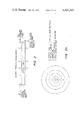
- FIG. 1 shows a Mach-Zehnder optical fiber interferometer and leads thereto for sensing external acoustic pressure.
- FIG. 2 shows an optical fiber with illustrated acoustic pressures which induce phase shifts.
- FIG. 2a is a cross-sectional view of one of the leads prepared according to the invention.
- FIG. 3 shows pressure sensitivity of a commercially available optical fiber waveguide versus coating thickness.
- FIG. 4 shows pressure sensitivity of an optical fiber according to Table II versus thickness of one of the coating.
- FIG. 5 shows pressure sensitivity of a commercially available optical fiber versus thickness of a calcium aluminate substrate.
- FIG. 6 shows pressure sensitivity of the same commercially available optical fiber versus thickness of a nickel substrate.
- FIG. 7 is a cross-sectional view of an alternate pressure insensitive waveguide.
- FIG. 1 shows apparatus in the form of a Mach-Zehnder optical fiber interferometer 10 for sensing acoustic wave pressure, magnetic field and temperature changes.
- Optical fibers 12 and 14, making up the sensing and reference arms, respectively are relatively short lines, usually just a few meters or less.
- the sensing arm is obviously exposed to the environment for encountering the conditions it is designed to sense.
- the reference arm may be isolated or shielded by the environment (means not illustrated) or since it is relatively short, it may be exposed to the environment along with the sensing arm. This, of course, depends upon its type of service.
- Optical fiber waveguide leads 16 and 16' on the other hand may be as long as one or more kilometers, again depending upon the type of service.
- the optical fiber interferometer performs in the usual manner.
- a light source 18 introduces light into lead optical fiber 16 where it travels and is subsequently divided to enter parallel arms 12 and 14.
- the light passes through the arms where a relative phase shift is induced in the sensing arm by a condition such as a magnetic field or acoustic wave.
- the light is then recombined and passed through lead 16' back to detector 20 where the extent of induced phase shifts is detected and converted into a meaningful reading which is in proportion to the magnitude of the conditions causing the phase shift.
- the present invention is directed to providing optical fiber waveguide leads 16 and 16' insensitive to varying acoustic pressure, thereby desensitizing the interferometer section from its environment.
- the sensitivity of an optical fiber is related to a combined effects of pressure induced fiber length changes (optical path length changes) and strain induced index of refraction change. These effects are generally of opposite polarity, and pressure insensitivity in the fiber can be obtained by balancing these effects one against the other.
- This is made possible, according to the invention disclosed herein, by providing a glass optical fiber (core and cladding), having a relatively low bulk modulus, with a glass substrate having a relatively high bulk modulus. The substrate can then be jacketed in several ways which will be discussed hereinafter.
- FIG. 2 is a representation of an optical fiber in an acoustic condition wherein pressures thereon cause dimension changes which result in both changes in optical path length and changes in the refractive index as previously explained under "Background of the Invention" heading.
- FIG. 2a is a cross-sectional representation of an optical fiber waveguide rendered pressure insensitive by a substrate and jacketing. It comprises a glass optical core A, having excellent light transmission qualities, with relatively low bulk modulus, and a glass cladding B, with good optical properties and with a refractive index slightly lower than that of the optical core. Together they define an optical fiber waveguide.
- Substrate C is provided to have a high bulk modulus.
- the substrate is preferably jacketed first with a soft coating D of rubber or plastic and then with a hard plastic coating E.
- the glass used for core A, cladding B and substrate C preferably have similar thermal expansion coefficients and softening temperatures. There are a number of possible combination of glass materials with related thicknesses which can be used to achieve pressure insensitive fibers.
- the FIG. 2a embodiment is based either on Table I or Table II data, but the substrate may be substituted for the soft first coating as will be described hereinafter.
- FIG. 3 shows the pressure sensitivity of a typical commercially available (ITT) single mode fiber as a function of the plastic coating (sold by DuPont under the trademark "Hytrel”) thickness, which usually varies in fibers.
- the fiber is nominally composed of a fused silica core with traces of GeO 2 , a cladding of 5% B 2 O 3 +95% S i O 2 , and a fused silica substrate.
- the fiber jacket consists of a 67.5 ⁇ m thick first coating of silicone and a 230 ⁇ m thick second coating of "Hytrel". The acoustic response of this fiber has been studied both experimentally and analytically in some detail.
- Table I lists all the parameters used to calculate the sensitivity, ⁇ / ⁇ P, of this fiber. From FIG. 3 it is seen that the largest contribution, ⁇ z l , is the part of ⁇ / ⁇ P, due to the fiber length change or optical path length change (first term in Eq. (1)).
- the ⁇ r P and ⁇ z P terms are due to the photo-elastic effect which changes the refractive index, and they give smaller contributions of opposite polarity.
- the "Hytrel" thickness increases (FIG. 3)
- the magnitude of the pressure sensitivity ( ⁇ / ⁇ P) increases rapidly due primarily to the ⁇ z l change.
- the sensitivity of an optical fiber is related to the combined effects of pressure induced fiber length changes and strain induced index of refraction effects. These effects are generally of opposite polarity (FIG. 3). Accordingly, pressure insensitivity can be achieved by balancing these effects. In particular, it is possible to achieve this by designing fibers consisting of a glass core with a relatively low bulk modulus, and a glass substrate with a high bulk modulus. The substrate can then be coated in the usual way, first with a soft rubber and then with a hard plastic.
- FIG. 4 shows the results of tests done on an optical fiber waveguide formed according to FIG. 2a with the composition, geometry, elastic and optical properties listed in Table II.
- the core and optical cladding both consist of a K 2 O-SiO 2 glass with slightly different molar ratios in order to obtain the refractive index difference needed for an optical fiber.
- the low bulk modulus K 2 O-SiO 2 glass has been found to have light transmission as good as fused silica.
- the substrate glass is a calcium aluminate glass (National Bureau of Standards D-308), NBS Report No. 5188, 1957), one of the many different glass compositions with high bulk modulus.
- the substrate is coated with silicon (first coating) and then with "Hytrel" (second coating), in order to protect the fiber.
- FIG. 4 shows the pressure sensitivity of the optical fiber waveguide like that illustrated in FIG. 2a with parameters of Table II as a function of "Hytrel" thickness. As shown, the waveguide sensitivity becomes negative as the "Hytrel" thickness increases. With a "Hytrel” thickness of 33 microns the sensitivity line crosses zero and the waveguide becomes insensitive.
- a pressure insensitive optical fiber waveguide can be achieved by applying a high bulk modulus glass substrate (e.g. calcium aluminate) or metal (e.g. nickel) as one of the coatings to commercially available fibers with core cladding and substrate characteristics identified in Table I.
- a high bulk modulus glass substrate e.g. calcium aluminate
- metal e.g. nickel
- These high silica fibers can be made pressure insensitive by coating the silica substrate first with a high bulk modulus glass substrate (e.g., calcium aluminate) followed by "Hytrel" as the second or outer coating.
- a high bulk modulus glass substrate e.g., calcium aluminate
- “Hytrel” as the second or outer coating.
- calcium aluminate is substituted for the silicon soft coating D illustrated in FIG. 2a.
- FIG. 5 shows the pressure sensitivity ( ⁇ / ⁇ P) of such a fiber as a function of the thickness of the substrate glass (calcium aluminate), which in this case has been substituted for soft silicone as first coating D.
- the second coating E is silicone of 400 microns o.d. substituted for "Hytrel" which normally defines the outer coating.
- the sensitivity of the uncoated ITT fiber is about -0.3 ⁇ 10 -12 /(dyn/cm 2 ).
- the fiber waveguide sensitivity decreases rapidly, and at about 56 ⁇ m substrate thickness, it becomes pressure insensitive. Further increase in the substrate thickness results only in a slow change in sensitivity.
- the calcium aluminate substrate is applied immediately outwardly of the original SiO 2 substrate of Table I and replaces the soft silicon first coating D.
- Soft silicon then replaces "Hytrel" as outer coating E.
- Such a composite can be made from commercially available uncoated ITT high silica fibers (Table I) by dip coating them in low melting temperature calcium aluminate glass. Thereafter, they can be further coated on a line with soft materials like silicone without substantial alteration of the fibers sensitivity. We point out, however, that such a fiber might be fragile since the substrate will be under tension due to the fact that it has a higher expansion coefficient than silica.
- the fiber can be made stress free by coating the high silica fiber with the high bulk modulus glass using the low temperature gel glass method. This, however, is a slower and more expensive process than the usual fiber drawing process.
- glasses high in SiO 2 , T i O 2 , N, etc. have small expansion coefficients
- glasses high in N, Ca, Al, etc. have high bulk modulus.
- a careful choice of the glass composition should give glasses with high bulk modulus and low expansion coefficient.
- FIG. 6 shows pressure sensitivity of the fiber as a function of a metal coating.
- the fiber is the uncoated ITT high silica fiber of Table I as identified in FIG. 5.
- the ITT fibers contain the initial SiO 2 substrate over which a nickel coating D is applied.
- the second or outer coating E in this case is "Hytrel" having a 100 ⁇ m o.d.
- the thickness of a nickel substrate has to be closer to the critical thickness than a calcium aluminate substrate to render the fiber substantially insensitive.
- a relatively simple alternate arrangement may be employed for providing a pressure insensitive waveguide. Such is illustrated in the cross-sectional view of FIG. 7.
- Optical core 25 is provided with a concentrically surrounding covering 27 which has an index of refraction (n 2 ) slightly less than that of the core (n 1 ), and a bulk modulus substantially higher than that of the core (e.g., around 90-125 ⁇ 10 10 dyn/cm versus 55-75 ⁇ 10 10 dyn/cm).
- the single layer 27 thereby establishes both a cladding and a substrate for optical core 25.
- As a cladding its wall thickness is relatively immaterial.
- Core 25 may be any of a variety of light transmitting material, e.g., doped silica or K 2 O-SiO 2 and the substrate may include several materials having the specified refractive index and bulk modulus, e.g., calcium aluminate.
- ceramic materials having high bulk modulus which can be utilized for forming the substrate to achieve desensitized fibers.
- Such ceramic products are commercially available, for example 3M alumina fiber, Youngs modulus 158 ⁇ 10 10 (dyn/cm 2 ); DuPont alumina fiber FP, Youngs modulus 347 ⁇ 10 10 (dyn/cm 2 ); and, Sumitomo alumina fiber, Youngs modulus 289 ⁇ 10 10 (dyn/cm 2 ). These values may be readily converted into bulk modulus.
- an optical fiber can be made pressure insensitive by concentrically surrounding the core and cladding (waveguide) with a high bulk modulus glass substrate as disclosed herein.
- the core and cladding glass may have a conventional high silica composition (Table I) or a relatively low bulk modulus composition (Table II).
- Table I high silica composition
- Table II relatively low bulk modulus composition
- the substrate glass must have a low expansion coefficient in addition to a high bulk modulus.
Landscapes
- Physics & Mathematics (AREA)
- General Physics & Mathematics (AREA)
- Optics & Photonics (AREA)
- Surface Treatment Of Glass Fibres Or Filaments (AREA)
Abstract
Description
              TABLE I
______________________________________
Pressure Sensitivity of Commercial (ITT) Fiber
               Optical         First  Second
        Optical
               Clad-   Sub-    Coating
                                      Coating
        Core   ding    strate  (Soft) (Hard)
______________________________________
Composition
          SiO.sub.2 +
                   95%     SiO.sub.2
                                 Silicone
                                        "Hytrel"
          traces   SiO.sub.2
          of GeO.sub.2
                   5%
          (0.1%)   B.sub.2 O.sub.3
Diameter  4.5      30      85    220    450
(μm)
Young's   72.45    64.14   72.45 0.0035 0.39
Modulus
(10.sup.10 dyn/cm.sup.2)
Poisson's Ratio
          0.17     0.149   0.17  0.49947
                                        0.483
P.sub.11  0.126
P.sub.12  0.27
n         1.458
______________________________________
 ##STR1##
              TABLE II
______________________________________
Pressure Insensitive Fiber According to Present Invention
                                 First Second
               Optical           (soft)
                                       (hard)
         Optical
               Clad-             Coat- Coat-
         Core  ding    Substrate ing   ing
______________________________________
Composition
           K.sub.2 O-
                   K.sub.2 O-
                           Calcium Sili- "Hy-
           SiO.sub.2
                   SiO.sub.2
                           Aluminate
                                   cone  trel"
           12-88   10-90   (NBS,
           (Mole   (Mole   D-308
           %)      %)      Glass)
                           (weight %)
                           CaO: 25.3
                           Al.sub.2 O.sub.3 : 27.6
                           MgO: 2.9
                           BeO: 5.9
                           ZrO.sub.2 : 5.9
                           SiO.sub.2 : 14.7
                           Ta.sub.2 O.sub.3 : 5.9
                           La.sub.2 O.sub.3 : 5.9
                           TiO.sub.2 : 5.9
Diameter   5       30      120     200   266
(μm)
Young's Modulus
           54      57      126.9   0.0035
                                         0.39
(10.sup.10 dyn/cm.sup.2)
Poisson's Ratio
           0.201   0.188   0.275   0.49947
                                         0.483
Thermal    70      61      67
Expansion
Coefficient
(10.sup.-7 /°C.)
Softening  722     772     790
Temperature
(°C.)
Refractive Index
           1.480   1.475
P.sub.11   0.1515
P.sub.12   0.2476
______________________________________
 ##STR2##
Claims (16)
Priority Applications (1)
| Application Number | Priority Date | Filing Date | Title |
|---|---|---|---|
| US06/256,289 US4427263A (en) | 1981-04-23 | 1981-04-23 | Pressure insensitive optical fiber |
Applications Claiming Priority (1)
| Application Number | Priority Date | Filing Date | Title |
|---|---|---|---|
| US06/256,289 US4427263A (en) | 1981-04-23 | 1981-04-23 | Pressure insensitive optical fiber |
Publications (1)
| Publication Number | Publication Date |
|---|---|
| US4427263A true US4427263A (en) | 1984-01-24 |
Family
ID=22971685
Family Applications (1)
| Application Number | Title | Priority Date | Filing Date |
|---|---|---|---|
| US06/256,289 Expired - Fee Related US4427263A (en) | 1981-04-23 | 1981-04-23 | Pressure insensitive optical fiber |
Country Status (1)
| Country | Link |
|---|---|
| US (1) | US4427263A (en) |
Cited By (28)
| Publication number | Priority date | Publication date | Assignee | Title |
|---|---|---|---|---|
| GB2145841A (en) * | 1983-09-01 | 1985-04-03 | American Telephone & Telegraph | Coated optical fiber |
| US4621896A (en) * | 1984-07-30 | 1986-11-11 | The United States Of America As Represented By The Secretary Of The Navy | Optical fibers with reduced pressure sensitivity to high frequency acoustic field |
| US4634217A (en) * | 1983-02-16 | 1987-01-06 | Felten & Guilleaume Energietechnik Gmbh | High tensile wire provided with light guide sensor |
| US4639079A (en) * | 1982-09-29 | 1987-01-27 | Corning Glass Works | Optical fiber preform and method |
| GB2178188A (en) * | 1985-07-24 | 1987-02-04 | Stc Plc | Triple plastics coated glass optical fibres |
| US4650003A (en) * | 1985-04-10 | 1987-03-17 | Systecon Inc. | Light path heat detector |
| US4709987A (en) * | 1985-12-10 | 1987-12-01 | The United States Of America As Represented By The Secretary Of The Navy | Pressure and temperature insensitive glass and optical coatings and fibers therefrom |
| US4842366A (en) * | 1987-03-05 | 1989-06-27 | Sumitomo Electric Industries, Ltd | Ceramic superconductor and light transmitting composite wire |
| US4979798A (en) * | 1989-10-18 | 1990-12-25 | The United States Of America As Represented By The Secretary Of The Navy | Pressure sensitive optical fiber having optimized coatings |
| US4994668A (en) * | 1989-09-01 | 1991-02-19 | The United States Of America As Represented By The Secretary Of The Navy | Planar fiber-optic interferometric acoustic sensor |
| US5015842A (en) * | 1989-06-01 | 1991-05-14 | United Technologies Corporation | High density fiber optic damage detection system |
| US5270538A (en) * | 1991-01-04 | 1993-12-14 | Hughes Aircraft Company | System for accurately detecting changes in temperature and pressure |
| US5343035A (en) * | 1992-12-21 | 1994-08-30 | The United States Of America As Represented By The Administrator Of The National Aeronautics And Space Administration | Strain sensor comprising a strain sensitive, two-mode optical |
| US5367376A (en) * | 1992-08-20 | 1994-11-22 | The United States Of America As Represented By The Secretary Of The Navy | Planar and linear fiber optic acoustic sensors embedded in an elastomer material |
| WO1998000739A1 (en) * | 1996-07-01 | 1998-01-08 | Corning Incorporated | Optical fiber with tantalum doped clad |
| US5780844A (en) * | 1996-04-23 | 1998-07-14 | The United States Of America As Represented By The Administrator Of The National Aeronautics And Space Administration | Strain insensitive optical phase locked loop |
| AU724900B2 (en) * | 1996-07-01 | 2000-10-05 | Corning Incorporated | Optical fiber with tantalum doped clad |
| US20040099800A1 (en) * | 2002-05-28 | 2004-05-27 | Nicholas Lagakos | Intensity modulated fiber optic microbend accelerometer |
| US20040151417A1 (en) * | 2002-05-28 | 2004-08-05 | Nicholas Lagakos | Intensity modulated fiber optic pressure sensor |
| US20060072887A1 (en) * | 2002-05-28 | 2006-04-06 | Nicholas Lagakos | Intensity modulated fiber optic static pressure sensor system |
| US20060280415A1 (en) * | 2005-03-17 | 2006-12-14 | Anthony Slotwinski | Precision length standard for coherent laser radar |
| US20090202195A1 (en) * | 2008-02-11 | 2009-08-13 | Nicholas Lagakos | Fiber Optic Pressure Sensors and Catheters |
| US20090252451A1 (en) * | 2008-04-03 | 2009-10-08 | The Government Of The Us, As Respresented By The Secretary Of The Navy | Intensity Modulated Fiber Optic Strain Sensor |
| US20110044575A1 (en) * | 2009-08-19 | 2011-02-24 | The Government Of The Us, As Represented By The Secretary Of The Navy | Miniature Fiber Optic Temperature Sensors |
| US20110280278A1 (en) * | 2010-05-17 | 2011-11-17 | Heraeus Electro-Nite International N.V. | Sensor Arrangement for Temperature Measurement and Method for Measurement |
| US20130211726A1 (en) * | 2009-12-23 | 2013-08-15 | Jeffery Joseph Mestayer | Detecting broadside and directional acoustic signals with a fiber optical distributed acoustic sensing (das) assembly |
| US20150211900A1 (en) * | 2012-08-17 | 2015-07-30 | Research Institute Of Innovative Technology For The Earth | Distribution measurement system for pressure, temperature, strain of material, monitoring method for carbon dioxide geological sequestration, assessing method for impact of carbon dioxide injection on integrity of strata, and monitoring method for freezing using same |
| US9494732B2 (en) | 2012-01-26 | 2016-11-15 | Nederlandse Organisatie Voor Toegepast-Natuurwetenschappelijk Onderzoek Tno | Transversal load insensitive optical waveguide, and optical sensor comprising a wave guide |
Citations (10)
| Publication number | Priority date | Publication date | Assignee | Title |
|---|---|---|---|---|
| US3980390A (en) | 1974-03-20 | 1976-09-14 | Sumitomo Electric Industries, Ltd. | Optical transmission fiber |
| US4000936A (en) | 1974-07-30 | 1977-01-04 | Bell Telephone Laboratories, Incorporated | Optical fiber jacket designs for minimum distortion loss |
| US4076382A (en) | 1975-11-12 | 1978-02-28 | Siemens Aktiengesellschaft | Optical cable with plastic multilayer sheath |
| US4089585A (en) | 1974-12-18 | 1978-05-16 | Bicc Limited | Optical guides |
| US4105284A (en) | 1976-05-10 | 1978-08-08 | Corning Glass Works | Buffered optical waveguide fiber |
| GB1524316A (en) | 1977-06-10 | 1978-09-13 | Gen Electric Co Ltd | Optical fibre waveguides |
| US4114981A (en) | 1976-05-26 | 1978-09-19 | Nippon Telegraph And Telephone Public Corporation | Optical fiber for communication |
| US4162397A (en) | 1978-06-28 | 1979-07-24 | The United States Of America As Represented By The Secretary Of The Navy | Fiber optic acoustic sensor |
| US4243298A (en) | 1978-10-06 | 1981-01-06 | International Telephone And Telegraph Corporation | High-strength optical preforms and fibers with thin, high-compression outer layers |
| US4334733A (en) | 1979-01-23 | 1982-06-15 | Nippon Telegraph & Telephone Public Corp. | Coated glass fibers for optical transmission |
-
1981
- 1981-04-23 US US06/256,289 patent/US4427263A/en not_active Expired - Fee Related
Patent Citations (10)
| Publication number | Priority date | Publication date | Assignee | Title |
|---|---|---|---|---|
| US3980390A (en) | 1974-03-20 | 1976-09-14 | Sumitomo Electric Industries, Ltd. | Optical transmission fiber |
| US4000936A (en) | 1974-07-30 | 1977-01-04 | Bell Telephone Laboratories, Incorporated | Optical fiber jacket designs for minimum distortion loss |
| US4089585A (en) | 1974-12-18 | 1978-05-16 | Bicc Limited | Optical guides |
| US4076382A (en) | 1975-11-12 | 1978-02-28 | Siemens Aktiengesellschaft | Optical cable with plastic multilayer sheath |
| US4105284A (en) | 1976-05-10 | 1978-08-08 | Corning Glass Works | Buffered optical waveguide fiber |
| US4114981A (en) | 1976-05-26 | 1978-09-19 | Nippon Telegraph And Telephone Public Corporation | Optical fiber for communication |
| GB1524316A (en) | 1977-06-10 | 1978-09-13 | Gen Electric Co Ltd | Optical fibre waveguides |
| US4162397A (en) | 1978-06-28 | 1979-07-24 | The United States Of America As Represented By The Secretary Of The Navy | Fiber optic acoustic sensor |
| US4243298A (en) | 1978-10-06 | 1981-01-06 | International Telephone And Telegraph Corporation | High-strength optical preforms and fibers with thin, high-compression outer layers |
| US4334733A (en) | 1979-01-23 | 1982-06-15 | Nippon Telegraph & Telephone Public Corp. | Coated glass fibers for optical transmission |
Non-Patent Citations (1)
| Title |
|---|
| Almeida et al., "On Line-Metal Coating of Optical Fibres," Optik, vol. 53,o. 3, Jun. 1979, pp. 231-233. |
Cited By (42)
| Publication number | Priority date | Publication date | Assignee | Title |
|---|---|---|---|---|
| US4639079A (en) * | 1982-09-29 | 1987-01-27 | Corning Glass Works | Optical fiber preform and method |
| US4634217A (en) * | 1983-02-16 | 1987-01-06 | Felten & Guilleaume Energietechnik Gmbh | High tensile wire provided with light guide sensor |
| GB2145841A (en) * | 1983-09-01 | 1985-04-03 | American Telephone & Telegraph | Coated optical fiber |
| US4621896A (en) * | 1984-07-30 | 1986-11-11 | The United States Of America As Represented By The Secretary Of The Navy | Optical fibers with reduced pressure sensitivity to high frequency acoustic field |
| US4650003A (en) * | 1985-04-10 | 1987-03-17 | Systecon Inc. | Light path heat detector |
| GB2178188B (en) * | 1985-07-24 | 1989-09-20 | Stc Plc | Plastics packaged optical fibres |
| GB2178188A (en) * | 1985-07-24 | 1987-02-04 | Stc Plc | Triple plastics coated glass optical fibres |
| US4709987A (en) * | 1985-12-10 | 1987-12-01 | The United States Of America As Represented By The Secretary Of The Navy | Pressure and temperature insensitive glass and optical coatings and fibers therefrom |
| US4842366A (en) * | 1987-03-05 | 1989-06-27 | Sumitomo Electric Industries, Ltd | Ceramic superconductor and light transmitting composite wire |
| US5015842A (en) * | 1989-06-01 | 1991-05-14 | United Technologies Corporation | High density fiber optic damage detection system |
| US4994668A (en) * | 1989-09-01 | 1991-02-19 | The United States Of America As Represented By The Secretary Of The Navy | Planar fiber-optic interferometric acoustic sensor |
| US4979798A (en) * | 1989-10-18 | 1990-12-25 | The United States Of America As Represented By The Secretary Of The Navy | Pressure sensitive optical fiber having optimized coatings |
| US5270538A (en) * | 1991-01-04 | 1993-12-14 | Hughes Aircraft Company | System for accurately detecting changes in temperature and pressure |
| US5367376A (en) * | 1992-08-20 | 1994-11-22 | The United States Of America As Represented By The Secretary Of The Navy | Planar and linear fiber optic acoustic sensors embedded in an elastomer material |
| US5343035A (en) * | 1992-12-21 | 1994-08-30 | The United States Of America As Represented By The Administrator Of The National Aeronautics And Space Administration | Strain sensor comprising a strain sensitive, two-mode optical |
| US5780844A (en) * | 1996-04-23 | 1998-07-14 | The United States Of America As Represented By The Administrator Of The National Aeronautics And Space Administration | Strain insensitive optical phase locked loop |
| WO1998000739A1 (en) * | 1996-07-01 | 1998-01-08 | Corning Incorporated | Optical fiber with tantalum doped clad |
| AU724900B2 (en) * | 1996-07-01 | 2000-10-05 | Corning Incorporated | Optical fiber with tantalum doped clad |
| US6998599B2 (en) | 2002-05-28 | 2006-02-14 | The United States Of America As Represented By The Secretary Of The Navy | Intensity modulated fiber optic microbend accelerometer |
| US20040099800A1 (en) * | 2002-05-28 | 2004-05-27 | Nicholas Lagakos | Intensity modulated fiber optic microbend accelerometer |
| US7020354B2 (en) | 2002-05-28 | 2006-03-28 | The United States Of America As Represented By The Secretary Of The Navy | Intensity modulated fiber optic pressure sensor |
| US20060072887A1 (en) * | 2002-05-28 | 2006-04-06 | Nicholas Lagakos | Intensity modulated fiber optic static pressure sensor system |
| US7460740B2 (en) | 2002-05-28 | 2008-12-02 | United States Of America As Represented By The Secretary Of The Navy | Intensity modulated fiber optic static pressure sensor system |
| US20040151417A1 (en) * | 2002-05-28 | 2004-08-05 | Nicholas Lagakos | Intensity modulated fiber optic pressure sensor |
| US20090323077A1 (en) * | 2005-03-17 | 2009-12-31 | Metris Usa, Inc. | Precision length standard for coherent laser radar |
| US20060280415A1 (en) * | 2005-03-17 | 2006-12-14 | Anthony Slotwinski | Precision length standard for coherent laser radar |
| US7925134B2 (en) | 2005-03-17 | 2011-04-12 | Nikon Metrology Nv | Precision length standard for coherent laser radar |
| US7697798B2 (en) | 2008-02-11 | 2010-04-13 | The United States Of America As Represented By The Secretary Of The Navy | Fiber optic pressure sensors and catheters |
| US20090202195A1 (en) * | 2008-02-11 | 2009-08-13 | Nicholas Lagakos | Fiber Optic Pressure Sensors and Catheters |
| US20090252451A1 (en) * | 2008-04-03 | 2009-10-08 | The Government Of The Us, As Respresented By The Secretary Of The Navy | Intensity Modulated Fiber Optic Strain Sensor |
| US7646946B2 (en) | 2008-04-03 | 2010-01-12 | The United States Of America As Represented By The Secretary Of The Navy | Intensity modulated fiber optic strain sensor |
| US8195013B2 (en) | 2009-08-19 | 2012-06-05 | The United States Of America, As Represented By The Secretary Of The Navy | Miniature fiber optic temperature sensors |
| US20110044373A1 (en) * | 2009-08-19 | 2011-02-24 | The Government of the US, as represented by the Secretary fo the Navy | Miniature Fiber Optic Temperature Sensor with Edge Reflector |
| US20110044575A1 (en) * | 2009-08-19 | 2011-02-24 | The Government Of The Us, As Represented By The Secretary Of The Navy | Miniature Fiber Optic Temperature Sensors |
| US8322919B2 (en) | 2009-08-19 | 2012-12-04 | The United States Of America, As Represented By The Secretary Of The Navy | Miniature fiber optic temperature sensor with edge reflector |
| US20130211726A1 (en) * | 2009-12-23 | 2013-08-15 | Jeffery Joseph Mestayer | Detecting broadside and directional acoustic signals with a fiber optical distributed acoustic sensing (das) assembly |
| US9080949B2 (en) * | 2009-12-23 | 2015-07-14 | Shell Oil Company | Detecting broadside and directional acoustic signals with a fiber optical distributed acoustic sensing (DAS) assembly |
| US20110280278A1 (en) * | 2010-05-17 | 2011-11-17 | Heraeus Electro-Nite International N.V. | Sensor Arrangement for Temperature Measurement and Method for Measurement |
| US8876372B2 (en) * | 2010-05-17 | 2014-11-04 | Heraeus Electro-Nite International N.V. | Sensor arrangement for temperature measurement and method for measurement |
| US9494732B2 (en) | 2012-01-26 | 2016-11-15 | Nederlandse Organisatie Voor Toegepast-Natuurwetenschappelijk Onderzoek Tno | Transversal load insensitive optical waveguide, and optical sensor comprising a wave guide |
| US20150211900A1 (en) * | 2012-08-17 | 2015-07-30 | Research Institute Of Innovative Technology For The Earth | Distribution measurement system for pressure, temperature, strain of material, monitoring method for carbon dioxide geological sequestration, assessing method for impact of carbon dioxide injection on integrity of strata, and monitoring method for freezing using same |
| US9829352B2 (en) * | 2012-08-17 | 2017-11-28 | Research Institute Of Innovative Technology For The Earth | Distribution measurement system for pressure, temperature, strain of material, monitoring method for carbon dioxide geological sequestration, assessing method for impact of carbon dioxide injection on integrity of strata, and monitoring method for freezing using same |
Similar Documents
| Publication | Publication Date | Title |
|---|---|---|
| US4427263A (en) | Pressure insensitive optical fiber | |
| US5563967A (en) | Fiber optic sensor having a multicore optical fiber and an associated sensing method | |
| US4979798A (en) | Pressure sensitive optical fiber having optimized coatings | |
| US6626043B1 (en) | Fluid diffusion resistant glass-encased fiber optic sensor | |
| US4621896A (en) | Optical fibers with reduced pressure sensitivity to high frequency acoustic field | |
| US5528367A (en) | In-line fiber etalon strain sensor | |
| JP2540293B2 (en) | Optical waveguide | |
| US4650281A (en) | Fiber optic magnetic field sensor | |
| US5633960A (en) | Spatially averaging fiber optic accelerometer sensors | |
| US5903685A (en) | Sensor arrangement | |
| US6215927B1 (en) | Sensing tapes for strain and/or temperature sensing | |
| US5627934A (en) | Concentric core optical fiber with multiple-mode signal transmission | |
| US4482205A (en) | Temperature-insensitive optical fibers | |
| US20160147011A1 (en) | Polarisation maintaining optical fiber package | |
| US4709987A (en) | Pressure and temperature insensitive glass and optical coatings and fibers therefrom | |
| US6611633B1 (en) | Coated fiber pressure sensors utilizing pressure release coating material | |
| Abe et al. | A strain sensor using twisted optical fibers | |
| Shiue | Design of double-coated optical fibers to minimize hydrostatic pressure induced microbending losses | |
| Wong | Effect of fiber coating on temperature sensitivity in polarimetric sensors | |
| EP0860686B1 (en) | Fiber optic gyro sensor coil with improved temperature stability | |
| Lagakos et al. | Ultrasonic sensitivity of coated fibers | |
| EP0131404A2 (en) | Fibre optic sensors | |
| JP2704193B2 (en) | Brillouin frequency shift standard equipment | |
| Xiao et al. | Review of Sensitivity-enhanced Optical Fiber and Cable Used in Distributed Acoustic Fiber Sensing | |
| Dandridge et al. | Optical Fiber Sensors |
Legal Events
| Date | Code | Title | Description |
|---|---|---|---|
| AS | Assignment |
Owner name: UNITED STATES OF AMERICA AS REPRESENTED BY THE SEC Free format text: ASSIGNMENT OF ASSIGNORS INTEREST.;ASSIGNORS:LAGAKOS, NICHOLAS;BUCARO, JOSEPH A.;REEL/FRAME:003944/0240 Effective date: 19810420 Owner name: NAVY, UNITED STATES OF AMERICA AS REPRESENTED BY T Free format text: ASSIGNMENT OF ASSIGNORS INTEREST;ASSIGNORS:LAGAKOS, NICHOLAS;BUCARO, JOSEPH A.;REEL/FRAME:003944/0240 Effective date: 19810420 |
|
| MAFP | Maintenance fee payment |
Free format text: PAYMENT OF MAINTENANCE FEE, 4TH YEAR, PL 96-517 (ORIGINAL EVENT CODE: M170); ENTITY STATUS OF PATENT OWNER: LARGE ENTITY Year of fee payment: 4 |
|
| MAFP | Maintenance fee payment |
Free format text: PAYMENT OF MAINTENANCE FEE, 8TH YEAR, PL 96-517 (ORIGINAL EVENT CODE: M171); ENTITY STATUS OF PATENT OWNER: LARGE ENTITY Year of fee payment: 8 |
|
| FEPP | Fee payment procedure |
Free format text: MAINTENANCE FEE REMINDER MAILED (ORIGINAL EVENT CODE: REM.); ENTITY STATUS OF PATENT OWNER: LARGE ENTITY |
|
| LAPS | Lapse for failure to pay maintenance fees | ||
| FP | Lapsed due to failure to pay maintenance fee |
Effective date: 19960121 |
|
| STCH | Information on status: patent discontinuation |
Free format text: PATENT EXPIRED DUE TO NONPAYMENT OF MAINTENANCE FEES UNDER 37 CFR 1.362 |