EP1862265A2 - Handwerkzeugmaschine mit Rutschkupplung - Google Patents
Handwerkzeugmaschine mit Rutschkupplung Download PDFInfo
- Publication number
- EP1862265A2 EP1862265A2 EP07108136A EP07108136A EP1862265A2 EP 1862265 A2 EP1862265 A2 EP 1862265A2 EP 07108136 A EP07108136 A EP 07108136A EP 07108136 A EP07108136 A EP 07108136A EP 1862265 A2 EP1862265 A2 EP 1862265A2
- Authority
- EP
- European Patent Office
- Prior art keywords
- axially
- sleeve
- hand tool
- control
- drive sleeve
- Prior art date
- Legal status (The legal status is an assumption and is not a legal conclusion. Google has not performed a legal analysis and makes no representation as to the accuracy of the status listed.)
- Withdrawn
Links
Images

Classifications
-
- B—PERFORMING OPERATIONS; TRANSPORTING
- B25—HAND TOOLS; PORTABLE POWER-DRIVEN TOOLS; MANIPULATORS
- B25D—PERCUSSIVE TOOLS
- B25D16/00—Portable percussive machines with superimposed rotation, the rotational movement of the output shaft of a motor being modified to generate axial impacts on the tool bit
- B25D16/003—Clutches specially adapted therefor
-
- B—PERFORMING OPERATIONS; TRANSPORTING
- B25—HAND TOOLS; PORTABLE POWER-DRIVEN TOOLS; MANIPULATORS
- B25B—TOOLS OR BENCH DEVICES NOT OTHERWISE PROVIDED FOR, FOR FASTENING, CONNECTING, DISENGAGING OR HOLDING
- B25B21/00—Portable power-driven screw or nut setting or loosening tools; Attachments for drilling apparatus serving the same purpose
- B25B21/02—Portable power-driven screw or nut setting or loosening tools; Attachments for drilling apparatus serving the same purpose with means for imparting impact to screwdriver blade or nut socket
- B25B21/026—Impact clutches
-
- B—PERFORMING OPERATIONS; TRANSPORTING
- B25—HAND TOOLS; PORTABLE POWER-DRIVEN TOOLS; MANIPULATORS
- B25D—PERCUSSIVE TOOLS
- B25D2211/00—Details of portable percussive tools with electromotor or other motor drive
- B25D2211/003—Crossed drill and motor spindles
-
- B—PERFORMING OPERATIONS; TRANSPORTING
- B25—HAND TOOLS; PORTABLE POWER-DRIVEN TOOLS; MANIPULATORS
- B25D—PERCUSSIVE TOOLS
- B25D2211/00—Details of portable percussive tools with electromotor or other motor drive
- B25D2211/06—Means for driving the impulse member
- B25D2211/068—Crank-actuated impulse-driving mechanisms
-
- B—PERFORMING OPERATIONS; TRANSPORTING
- B25—HAND TOOLS; PORTABLE POWER-DRIVEN TOOLS; MANIPULATORS
- B25D—PERCUSSIVE TOOLS
- B25D2216/00—Details of portable percussive machines with superimposed rotation, the rotational movement of the output shaft of a motor being modified to generate axial impacts on the tool bit
- B25D2216/0007—Details of percussion or rotation modes
- B25D2216/0023—Tools having a percussion-and-rotation mode
-
- B—PERFORMING OPERATIONS; TRANSPORTING
- B25—HAND TOOLS; PORTABLE POWER-DRIVEN TOOLS; MANIPULATORS
- B25D—PERCUSSIVE TOOLS
- B25D2217/00—Details of, or accessories for, portable power-driven percussive tools
- B25D2217/0011—Details of anvils, guide-sleeves or pistons
- B25D2217/0019—Guide-sleeves
-
- B—PERFORMING OPERATIONS; TRANSPORTING
- B25—HAND TOOLS; PORTABLE POWER-DRIVEN TOOLS; MANIPULATORS
- B25D—PERCUSSIVE TOOLS
- B25D2250/00—General details of portable percussive tools; Components used in portable percussive tools
- B25D2250/045—Cams used in percussive tools
-
- B—PERFORMING OPERATIONS; TRANSPORTING
- B25—HAND TOOLS; PORTABLE POWER-DRIVEN TOOLS; MANIPULATORS
- B25D—PERCUSSIVE TOOLS
- B25D2250/00—General details of portable percussive tools; Components used in portable percussive tools
- B25D2250/165—Overload clutches, torque limiters
-
- B—PERFORMING OPERATIONS; TRANSPORTING
- B25—HAND TOOLS; PORTABLE POWER-DRIVEN TOOLS; MANIPULATORS
- B25D—PERCUSSIVE TOOLS
- B25D2250/00—General details of portable percussive tools; Components used in portable percussive tools
- B25D2250/321—Use of balls
Definitions
- the invention refers to an at least partially rotating and axially striking hand tool such as a combination hammer with a, a gas spring having impact mechanism and arranged on the guide tube of the gas spring slip clutch.
- slip clutch safety clutch When designed as a slip clutch safety clutch, the separation of the power flow occurs as soon as an allowable limit torque is exceeded. If the slip clutch is also designed as a frictionally engaged detent coupling, in the event of a tool blockage during repeated engagement of the force flow, respectively, torque fluctuations are generated which can contribute to a breakage of the drill head from the entanglement, wherein the torque fluctuations must be absorbed by the user substantially.
- another safety clutch is also designed as an electronically controlled magnetic coupling and arranged in the power flow before the transmission gear behind the high-speed motor, where much lower dome torques occur.
- EP1207018 is in a rotating and axially striking hand tool a safety clutch designed as an electronically controlled magnetic coupling and arranged in the power flow before the transmission gear directly behind the fast-rotating motor.
- a sliding clutch comprising the rotatable guide tube has a drive sleeve rotatably driven by a bevel pinion and an inner cone sleeve axially prestressed with a compression spring which presses radially displaceable balls in rotational receiving holes of the drive sleeve inward into suitable ball hollows of the guide tube.
- DE10033100 has a rotating and axially striking hand tool on a striking mechanism with a rotating guide tube, in which a percussion piston is driven axially striking a gas spring, wherein the guide tube comprehensive, with cam axially toothed slip clutch has a driven by a bevel pinion drive sleeve and an output sleeve, the are biased axially against each other with a spring, wherein the output sleeve is axially displaceable rotatably connected to the guide tube.
- the object of the invention is the realization of a rotating and axially striking hand tool, which generates tangential impact pulses in the appropriate use case.
- an at least partially rotating and axially striking hand tool a percussion with a guide tube in which a percussion piston is driven axially striking a gas spring, and a rotationally driven
- the guide tube comprehensive, with cam axially toothed slip clutch with a drive sleeve and output sleeve on each other are pressure-biased axially with a spring, wherein the drive sleeve with a coaxial to this control sleeve via balls, which in each case partially engage in two partially oppositely arranged control contours of the drive sleeve and the control sleeve, positively connected and so positively constrained, that, when a limit torque is exceeded, the axially axially biased with the spring drive sleeve relative to the control sleeve axially offset and rotated.
- the first control contour is formed as a (with respect to the ball) wide pocket with at least one axially inclined leg and the second control contour as an at least partially axially opposite obliquely (more advantageously same amount as the leg) extending, elongated groove, whereby on the opposing gradients of the leg and the groove, the limit torque is defined, in which the tangential impact begins by the drive sleeve within the free space of the wide pocket is forcibly accelerated by the now possible relaxation of the spring and tangentially strikes against the output sleeve.
- the first control contour is formed as a triangular pocket with axially spring-side tip and two axially obliquely extending leg and the second control contour as an axially opposite V-shaped angled oblique, elongated groove, whereby in both directions of rotation of the tool holder when exceeding a limit torque each Tangentialschlagimpulse be generated, which is advantageous for solving a permanent tool blockage.
- control sleeve is arranged coaxially within the drive sleeve, whereby the drive sleeve with the cam with respect to the outside slip clutch is exposed.
- the output sleeve is directly, advantageously one piece, connected to the tool holder, whereby the tangential impact pulses are transmitted to the rotary impact tool with minimal damping.
- the torque-transmitting flank surfaces of the cams of the drive sleeve and the output sleeve of the axially toothed slip clutch are each oriented exactly tangentially, so that no radial or axial force components occur in the engaged state during rotational engagement.
- At least two circumferentially symmetrically distributed cams per drive sleeve and output sleeve are present, whereby no axial bending moment is generated upon rotational driving.
- a further safety clutch further advantageously designed as an electronically controlled magnetic coupling, arranged in the power flow between the driving motor and the transmission gear, which is further advantageously designed as a bevel gear, whereby the power flow is redundantly interruptible in the event of a tool blockage.
- different criteria can be used to trigger both clutches, for example, different high limit torques occurring at the rotary impact tool or calculated Grenzausschitch of the housing.
- the output sleeve 12 is integrally formed directly connected to the tool holder 3.
- another safety clutch 17 is arranged in the form of an electronically controlled magnetic coupling.
- the drive sleeve 11 is connected in a form-locking manner to the control sleeve 14, which is coaxial to the latter, via balls 18 which in each case partially engage in two control contours 19a, 19b of the drive sleeve 11 and the control sleeve 14 arranged partially opposite one another.
- control cam 14 formed by the first control contour 19a (shown in phantom, because of the cut-away part) as a respect to the ball 18 wide triangular pocket with axial spring-side tip and each obliquely extending legs and formed formed by the drive sleeve 11 second control contour 19b formed as an axially opposite V-shaped angled groove, the same amount as the legs axially opposite to each other obliquely.
Landscapes
- Engineering & Computer Science (AREA)
- Mechanical Engineering (AREA)
- Percussive Tools And Related Accessories (AREA)
- Drilling And Boring (AREA)
Abstract
Description
- Die Erfindung bezeichnet eine zumindest teilweise drehende und axial schlagende Handwerkzeugmaschine wie einen Kombihammer mit einem, eine Gasfeder aufweisenden, Schlagwerk und einer auf dem Führungsrohr der Gasfeder angeordneten Rutschkupplung.
- Da es insbesondere beim Schlagdrehbohren in armiertem Beton zum Verhaken des Bohrkopfes an einem eingebetteten Armierungseisen und somit zu einem Verdrehen des Gehäuses kommen kann, wird im Falle einer Werkzeugblockade der Kraftfluss mit einer zwischen dem antreibenden Motor und der Werkzeugaufnahme angeordneten Sicherheitskupplung zuverlässig getrennt.
- Bei einer als Rutschkupplung ausgebildeten Sicherheitskupplung erfolgt die Trennung des Kraftflusses, sobald ein zulässiges Grenzdrehmoment überschritten wird. Ist die Rutschkupplung zudem als reibformschlüssige Rastkupplung ausgebildet, werden im Falle einer Werkzeugblockade beim wiederholten Einrasten des Kraftflusses jeweils Drehmomentschwankungen erzeugt, die zu einem Losreissen des Bohrkopfes aus der Verhakung beitragen können, wobei die Drehmomentschwankungen im wesentlichen vom Nutzer aufgenommen werden müssen.
- Insbesondere bei leistungsstarken Handwerkzeugmaschinen mit über 1000 Watt Leistung ist zudem eine weitere Sicherheitskupplung als elektronisch gesteuerte Magnetkupplung ausgebildet und im Kraftfluss vor dem Übersetzungsgetriebe hinter dem schnell drehenden Motor angeordnet, wo wesentlich geringere Kuppeldrehmomente auftreten.
- Nach der
DE4304899 ist bei einer drehenden und axial schlagenden Handwerkzeugmaschine auf dem Führungsrohr eine erste, verriegelbare Rutschkupplung und im Kraftfluss vor dem Übersetzungsgetriebe eine zweite Rutschkupplung angeordnet. - Nach der
EP1207018 ist bei einer drehenden und axial schlagenden Handwerkzeugmaschine eine Sicherheitskupplung als elektronisch gesteuerte Magnetkupplung ausgebildet und im Kraftfluss vor dem Übersetzungsgetriebe direkt hinter dem schnell drehenden Motor angeordnet. - Nach der
DE3804414 weist bei einer drehenden und axial schlagenden Handwerkzeugmaschine eine das drehbare Führungsrohr umfassende Rutschkupplung eine von einem Kegelritzel drehend angetriebene Antriebshülse und eine mit einer Druckfeder axial vorgespannte Innenkegelhülse auf, die in Drehmitnahmelöchern der Antriebshülse radial versetzbare Kugeln zur Drehmitnahme nach innen in passende Kugelmulden des Führungsrohrs drückt. - Nach der
DE10033100 weist eine drehende und axial schlagende Handwerkzeugmaschine ein Schlagwerk mit einem drehenden Führungsrohr auf, in welchem ein Schlagkolben über eine Gasfeder axial schlagend angetrieben ist, wobei eine das Führungsrohr umfassende, mit Nocken axialverzahnte Rutschkupplung eine von einem Kegelritzel drehend angetriebene Antriebshülse und eine Abtriebshülse aufweist, die gegeneinander mit einer Feder axial druckvorgespannt sind, wobei die Abtriebshülse axial verschieblich drehfest mit dem Führungsrohr verbunden ist. - Zudem sind nach den
US2907240 ,GB963533 - Die Aufgabe der Erfindung besteht in der Realisierung einer drehenden und axial schlagenden Handwerkzeugmaschine, welche Tangentialschlagimpulse auch im zweckentsprechenden Nutzungsfall erzeugt.
- Die Aufgabe wird im Wesentlichen durch die Merkmale des Anspruchs 1 gelöst. Vorteilhafte Weiterbildungen ergeben sich aus den Unteransprüchen.
- So weist eine zumindest teilweise drehende und axial schlagende Handwerkzeugmaschine ein Schlagwerk mit einem Führungsrohr, in welchem ein Schlagkolben über eine Gasfeder axial schlagend angetrieben ist, und eine drehend angetriebene, das Führungsrohr umfassende, mit Nocken axialverzahnte Rutschkupplung mit einer Antriebshülse und Abtriebshülse auf, die gegeneinander mit einer Feder axial druckvorgespannt sind, wobei die Antriebshülse mit einer zu dieser koaxialen Steuerhülse über Kugeln, welche jeweils teilweise in zwei teilweise gegenüberliegend angeordnete Steuerkonturen der Antriebshülse sowie der Steuerhülse eingreifen, formschlüssig verbunden sowie derart zwangsgeführt ist, dass sich bei Überschreitung eines Grenzdrehmoments die mit der Feder axial druckvorgespannte Antriebshülse gegenüber der Steuerhülse axial versetzt und verdreht.
- Durch die mit einer zwangsgeführt verdrehten Antriebshülse ausgebildete axialverzahnte Rutschkupplung treffend beim Einrasten die Nocken in der Art eines Tangentialschlagwerks schlagend aufeinander und erzeugen an der Abtriebshülse direkt Tangentialschlagimpulse, welche sich dämpfungsarm über die Werkzeugaufnahme und das Schlagbohrwerkzeug bis zum Bohrkopf fortpflanzen. Da die Tangentialschlagimpulse wesentlich kurzzeitiger dafür aber mit wesentlich höheren Drehmomentspitzen als die beim blossen Einrasten des Kraftflusses entstehenden Drehmomentschwankungen wirken, kann eine sich allfällig mit steigendem Drehmoment anbahnende Werkzeugblockade zumeist bereits nach wenigen Tangentialschlägen überwunden werden, ohne dass es zu einer dauerhaften Werkzeugblockade kommt, die zur dauerhaften Unterbrechung des Kraftflusses führt. Zudem werden die kurzzeitigen Tangentialschlagimpulse im Wesentlichen vom Trägheitsmoment der Handwerkzeugmaschine abgefangen sind somit für den Nutzer kaum spürbar.
- Vorteilhaft ist die erste Steuerkontur als eine (bezüglich der Kugel) weite Tasche mit zumindest einem axial schräg verlaufenden Schenkel und die zweite Steuerkontur als eine zumindest teilweise axial entgegengesetzt schräg (weiter vorteilhaft gleichen Betrags wie der Schenkel) verlaufende, längliche Nut ausgebildet, wodurch über die gegensinnigen Steigungen des Schenkels und der Nut das Grenzdrehmoment definiert ist, bei welchem der Tangentialschlag einsetzt, indem durch die nunmehr mögliche Entspannung der Feder die Antriebshülse innerhalb des Freiraums der weiten Tasche zwangfrei beschleunigt wird und tangential gegen die Abtriebshülse schlägt.
- Vorteilhaft ist die erste Steuerkontur als dreieckförmige Tasche mit axial federseitiger Spitze und jeweils zwei axial schräg verlaufenden Schenkel und die zweite Steuerkontur als eine axial entgegengesetzt V-förmig abgewinkelte schräg verlaufende, längliche Nut ausgebildet, wodurch in beiden Drehrichtungen der Werkzeugaufnahme bei Überschreitung eines Grenzdrehmoments jeweils Tangentialschlagimpulse erzeugt werden, was zum Lösen einer dauerhaften Werkzeugblockade vorteilhaft ist.
- Vorteilhaft ist die Steuerhülse koaxial innerhalb der Antriebshülse angeordnet, wodurch die Antriebshülse mit den Nocken bezüglich der Rutschkupplung aussen frei liegt.
- Vorteilhaft ist die Abtriebshülse direkt, weiter vorteilhaft einteilig, mit der Werkzeugaufnahme verbunden, wodurch die Tangentialschlagimpulse mit minimaler Dämpfung auf das Drehschlagwerkzeug übertragen werden.
- Vorteilhaft sind jeweils die drehmomentübertragenden Flankenflächen der Nocken der Antriebshülse und der Abtriebshülse der axialverzahnte Rutschkupplung exakt tangential orientiert, wodurch im eingekuppelten Zustand bei Drehmitnahme keine radialen oder axialen Kraftkomponenten auftreten.
- Vorteilhaft sind zumindest zwei umfänglich symmetrisch verteilte Nocken je Antriebshülse und Abtriebshülse vorhanden, wodurch bei Drehmitnahme kein axiales Biegemoment erzeugt wird.
- Vorteilhaft ist eine weitere Sicherheitskupplung, weiter vorteilhaft als elektronisch gesteuerte Magnetkupplung ausgebildet, im Kraftfluss zwischen dem antreibenden Motor und dem Übersetzungsgetriebe angeordnet, welches weiter vorteilhaft als ein Kegelgetriebe ausgebildet ist, wodurch im Falle einer Werkzeugblockade der Kraftfluss redundant unterbrechbar ist. Zudem können zum Auslösen beider Kupplungen unterschiedliche Kriterien zum Einsatz kommen, bspw. unterschiedlich hohe am Drehschlagwerkzeug auftretende Grenzdrehmomente oder berechnete Grenzauslenkungen des Gehäuses.
- Die Erfindung wird bezüglich eines vorteilhaften Ausführungsbeispiels näher erläutert mit:
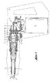
- Fig. 1
- als Handwerkzeugmaschine im Längsschnitt
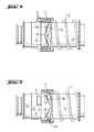
- Fig. 2
- als Einzelheit mit Rutschkupplung im Längsschnitt (Linie II-II in Fig. 3)
- Fig. 3
- als Querschnitt (Linie III-III in Fig. 2)
- Fig. 4
- und Fig. 5 als 90°versetzte Teillängsschnitte (Linien IV-IV bzw. V-V in Fig. 3)
- Nach Fig. 1 weist eine bezüglich einer Achse A (wahlweise im Rechts- oder Linkslauf) drehend und axial schlagend ein Drehbohrwerkzeug 2 über eine Werkzeugaufnahme 3 antreibende Handwerkzeugmaschine 4 ein Schlagwerk 5 mit einem Führungsrohr 6 auf, in welchem ein Schlagkolben 7 über eine Gasfeder 8 axial schlagend angetrieben ist. Zudem ist als Sicherheitskupplung eine drehend angetriebene, das Führungsrohr 6 umfassende, mit Nocken 9 (Fig. 4) axialverzahnte Rutschkupplung 10 mit einer Antriebshülse 11 und Abtriebshülse 12 vorhanden, die gegeneinander mit einer Feder 13 axial druckvorgespannt sind. Koaxial innerhalb der Antriebshülse 11 ist eine Steuerhülse 14 angeordnet, die über Kugeln 18 mit der Antriebshülse 11 verbunden ist. Die Abtriebshülse 12 ist einteilig direkt mit der Werkzeugaufnahme 3 verbunden ausgebildet. Im Kraftfluss zwischen einem antreibenden Motor 15 und einem als Kegelgetriebe ausgebildeten Übersetzungsgetriebe 16 für den Drehantrieb ist eine weitere Sicherheitskupplung 17 in der Form einer elektronisch gesteuerten Magnetkupplung angeordnet.
- Nach den Fig. 2 bis Fig. 5 ist die Antriebshülse 11 mit der zu dieser koaxialen Steuerhülse 14 über Kugeln 18, welche jeweils teilweise in zwei teilweise gegenüberliegend angeordnete Steuerkonturen 19a, 19b der Antriebshülse 11 sowie der Steuerhülse 14 eingreifen, formschlüssig verbunden. Bei Überschreitung eines Grenzdrehmoments der Rutschkupplung 10 wird die mit der Feder 13 axial gegen die Steuerhülse 14 druckvorgespannte Antriebshülse 11 gegenüber der Steuerhülse 14 soweit axial versetzt und vermittelt über den Zwang der Steuerkonturen 19a, 19b verdreht, bis die exakt tangential orientierten drehmomentübertragenden Flankenflächen 20 (Fig. 5) der jeweils beiden umlaufend symmetrisch versetzten, gegenseitig axial ineinandergreifenden Nocken 9 (Fig. 5, teilweise gestrichelt dargestellt, da des weggeschnittenen Teils) ausser Kontakt sind und reibungsarm aneinander vorbeidrehen. Die nach dem Vorbeigleiten ermöglichte Entspannung der Feder 13 bewirkt sowohl eine axiale Zurückversetzung als auch innerhalb des Freiraumes der Steuerkonturen 19a, 19b eine bezüglich der Steuerhülse 14 freie Drehbeschleunigung der Antriebshülse 11, welche über die drehmomentübertragenden Flankenflächen 20 der nun wieder ineinandergreifenden Nocken 9 gegen die Abtriebshülse 12 schlägt und somit ihre gesamte Rotationsenergie in einen kurzzeitigen Tangentialstoss transformiert, der sich über die Werkzeugaufnahme 3 (Fig. 1) auf das Drehbohrwerkzeug 2 (Fig. 1) überträgt. Dazu ist nach den Fig. 4 und Fig. 5 die von der Steuerhülse 14 ausgebildete erste Steuerkontur 19a (gestrichelt dargestellt, da des weggeschnittenen Teils) als eine bezüglich der Kugel 18 weite dreieckförmige Tasche mit axial federseitiger Spitze und jeweils schräg verlaufenden Schenkeln ausgebildet und die von der Antriebshülse 11 ausgebildete zweite Steuerkontur 19b als eine axial entgegengesetzt V-förmig abgewinkelte Nut ausgebildet, die gleichen Betrags wie die Schenkel axial jeweils entgegengesetzt schräg verläuft.
Claims (8)
- Zumindest teilweise drehende und axial schlagende Handwerkzeugmaschine mit einem Schlagwerk (5) mit einem Führungsrohr (6), in welchem ein Schlagkolben (7) über eine Gasfeder (8) axial schlagend angetrieben ist, und mit einer drehend angetriebenen, das Führungsrohr (6) umfassenden, mit Nocken (9) axialverzahnte Rutschkupplung (10) mit einer Antriebshülse (11) und einer Abtriebshülse (12), die gegeneinander mit einer Feder (13) axial druckvorgespannt sind, dadurch gekennzeichnet, dass die Antriebshülse (11) mit einer zu dieser koaxialen Steuerhülse (14) über Kugeln (18), welche jeweils teilweise in zwei teilweise gegenüberliegend angeordnete Steuerkonturen (19a, 19b) der Antriebshülse (11) sowie der Steuerhülse (14) eingreifen, formschlüssig verbunden sowie derart zwangsgeführt ist, damit sich bei Überschreitung eines Grenzdrehmoments die mit der Feder (13) axial druckvorgespannte Antriebshülse (11) gegenüber der Steuerhülse (14) axial versetzt und verdreht.
- Handwerkzeugmaschine nach Anspruch 1, dadurch gekennzeichnet, dass die erste Steuerkontur (19a) als eine weite Tasche mit zumindest einem axial schräg verlaufenden Schenkel und die zweite Steuerkontur (19b) als eine zumindest teilweise axial entgegengesetzt schräg verlaufende, längliche Nut ausgebildet ist.
- Handwerkzeugmaschine nach Anspruch 2, dadurch gekennzeichnet, dass die erste Steuerkontur (19a) als dreieckförmige Tasche mit axial federseitiger Spitze und jeweils zwei axial schräg verlaufenden Schenkel und die zweite Steuerkontur (19b) als eine axial entgegengesetzt V-förmig abgewinkelte schräg verlaufende, längliche Nut ausgebildet ist.
- Handwerkzeugmaschine nach einem der Ansprüche 1 bis 3, dadurch gekennzeichnet, dass die Steuerhülse (14) koaxial innerhalb der Antriebshülse (11) angeordnet ist.
- Handwerkzeugmaschine nach einem der Ansprüche 1 bis 4, dadurch gekennzeichnet, dass die Abtriebshülse (12) direkt mit der Werkzeugaufnahme (2) verbunden ist.
- Handwerkzeugmaschine nach einem der Ansprüche 1 bis 5, dadurch gekennzeichnet, dass jeweils die drehmomentübertragenden Flankenflächen (20) der Nocken (9) der Antriebshülse (11) und der Abtriebshülse (12) der axialverzahnte Rutschkupplung (10) exakt tangential orientiert sind.
- Handwerkzeugmaschine nach einem der Ansprüche 1 bis 6, dadurch gekennzeichnet, dass zumindest zwei umfänglich symmetrisch verteilte Nocken (9) je Antriebshülse (11) und Abtriebshülse (12) vorhanden sind.
- Handwerkzeugmaschine nach einem der Ansprüche 1 bis 7, dadurch gekennzeichnet, dass eine weitere Sicherheitskupplung (17) im Kraftfluss zwischen dem antreibenden Motor (15) und dem Übersetzungsgetriebe (16) angeordnet ist.
Applications Claiming Priority (1)
| Application Number | Priority Date | Filing Date | Title |
|---|---|---|---|
| DE102006000252A DE102006000252A1 (de) | 2006-05-30 | 2006-05-30 | Handwerkzeugmaschine mit Rutschkupplung |
Publications (2)
| Publication Number | Publication Date |
|---|---|
| EP1862265A2 true EP1862265A2 (de) | 2007-12-05 |
| EP1862265A3 EP1862265A3 (de) | 2013-01-02 |
Family
ID=38457708
Family Applications (1)
| Application Number | Title | Priority Date | Filing Date |
|---|---|---|---|
| EP07108136A Withdrawn EP1862265A3 (de) | 2006-05-30 | 2007-05-14 | Handwerkzeugmaschine mit Rutschkupplung |
Country Status (3)
| Country | Link |
|---|---|
| US (1) | US7861797B2 (de) |
| EP (1) | EP1862265A3 (de) |
| DE (1) | DE102006000252A1 (de) |
Cited By (2)
| Publication number | Priority date | Publication date | Assignee | Title |
|---|---|---|---|---|
| WO2009109246A1 (de) * | 2008-03-03 | 2009-09-11 | Robert Bosch Gmbh | Handwerkzeugmaschine |
| DE102010062014B3 (de) * | 2010-11-26 | 2012-05-10 | Hilti Aktiengesellschaft | Handwerkzeugmaschine |
Families Citing this family (22)
| Publication number | Priority date | Publication date | Assignee | Title |
|---|---|---|---|---|
| SE532395C2 (sv) * | 2008-05-08 | 2010-01-12 | Atlas Copco Tools Ab | Kraftverktyg för åtdragning av skruvförband samt frikoppling |
| EP2138273B1 (de) * | 2008-06-25 | 2012-02-15 | Robert Bosch GmbH | Drehwerkzeug mit einem manuellen Ratschenmechanismus |
| JP5395620B2 (ja) * | 2009-11-02 | 2014-01-22 | 株式会社マキタ | 打撃工具 |
| CN101949260B (zh) * | 2010-07-22 | 2013-07-24 | 浙江师范大学 | 一种储能后释放的冲击锤的辅锤机构及储能式冲击锤 |
| CN102371573A (zh) * | 2010-08-10 | 2012-03-14 | 南京德朔实业有限公司 | 电动工具 |
| JP2012223844A (ja) * | 2011-04-18 | 2012-11-15 | Makita Corp | ハンマドリル |
| DE102011080800A1 (de) * | 2011-08-11 | 2013-02-14 | Hilti Aktiengesellschaft | Handwerkzeugmaschine |
| DE102011081617A1 (de) * | 2011-08-26 | 2013-02-28 | Hilti Aktiengesellschaft | Handgehaltene Werkzeugmaschine |
| DE102012013934A1 (de) * | 2012-07-16 | 2014-01-16 | Krohne Ag | Verfahren zum Betreiben einer Einstellvorrichtung |
| EP2979819A4 (de) * | 2013-03-26 | 2016-11-16 | Hitachi Koki Kk | Elektrowerkzeug |
| EP3040164A4 (de) * | 2013-08-30 | 2017-04-05 | Hitachi Koki Co., Ltd. | Bohrwerkzeug |
| EP2857149A1 (de) * | 2013-10-03 | 2015-04-08 | HILTI Aktiengesellschaft | Handwerkzeugmaschine |
| GB201421576D0 (en) | 2014-12-04 | 2015-01-21 | Black & Decker Inc | Drill |
| GB201421577D0 (en) * | 2014-12-04 | 2015-01-21 | Black & Decker Inc | Drill |
| US10149433B2 (en) * | 2015-07-10 | 2018-12-11 | Combined Manufacturing Inc. | Combination blade and cord weed cutter-trimmer head device |
| EP3117962A1 (de) * | 2015-07-17 | 2017-01-18 | HILTI Aktiengesellschaft | Handwerkzeugmaschine |
| US10406667B2 (en) * | 2015-12-10 | 2019-09-10 | Black & Decker Inc. | Drill |
| GB2545237A (en) | 2015-12-10 | 2017-06-14 | Black & Decker Inc | Planetray gear system |
| CN107914248A (zh) * | 2018-01-12 | 2018-04-17 | 江苏恒丰电动工具有限公司 | 一种移动式拨扭 |
| US11826891B2 (en) * | 2019-10-21 | 2023-11-28 | Makita Corporation | Power tool having hammer mechanism |
| US11890728B2 (en) | 2021-05-19 | 2024-02-06 | Nextgen Aerospace Technologies, Llc | Concentrated longitudinal acoustical/ultrasonic energy fastener design and manipulation system |
| US11872680B2 (en) | 2021-07-16 | 2024-01-16 | Black & Decker Inc. | Impact power tool |
Citations (4)
| Publication number | Priority date | Publication date | Assignee | Title |
|---|---|---|---|---|
| DE4304899A1 (de) * | 1993-02-11 | 1994-08-18 | Hitachi Koki Kk | Rutschmomentänderungseinrichtung für ein Schlagwerkzeug |
| DE19505068A1 (de) * | 1994-02-25 | 1995-09-07 | Hitachi Koki Kk | Geräuschreduzierungsmechanismus für Schlagwerkzeuge |
| US20060024141A1 (en) * | 2004-07-30 | 2006-02-02 | Hilti Aktiengesellschaft | Power tool with an intermittent angular torque pulse |
| DE102004047470A1 (de) * | 2004-09-30 | 2006-04-06 | Robert Bosch Gmbh | Handwerkzeugmaschine, insbesondere Bohr- und/oder Schlaghammer |
Family Cites Families (29)
| Publication number | Priority date | Publication date | Assignee | Title |
|---|---|---|---|---|
| US2068745A (en) * | 1935-06-26 | 1937-01-26 | Michael O Meara J | Power tool |
| US2220711A (en) * | 1936-01-07 | 1940-11-05 | Ingersoll Rand Co | Impact tool |
| US2128761A (en) * | 1937-07-03 | 1938-08-30 | Ingersoll Rand Co | Impact wrench |
| US2160150A (en) * | 1937-10-21 | 1939-05-30 | Ingersoll Rand Co | Impact wrench |
| US2753965A (en) * | 1951-10-03 | 1956-07-10 | Thor Power Tool Co | Impact tools |
| US2889902A (en) * | 1955-06-29 | 1959-06-09 | Ingersoll Rand Co | Deceleration torque limiter for impact tools |
| US2907240A (en) * | 1957-01-31 | 1959-10-06 | Bosch Gmbh Robert | Power-operated, rotary impact-type hand tool |
| DE1218370B (de) * | 1963-09-27 | 1966-06-02 | Bosch Gmbh Robert | Motorisch angetriebenes, insbesondere tragbares Schraubgeraet |
| US3275116A (en) * | 1964-10-12 | 1966-09-27 | Airetool Mfg Company | Air powered tool with overload cutoff |
| US3616883A (en) * | 1970-06-08 | 1971-11-02 | Black & Decker Mfg Co | Adjustable clutch |
| JPS5834265B2 (ja) * | 1980-03-05 | 1983-07-26 | 瓜生製作株式会社 | エヤ−ドライバ−のクラツチ式トルク制御装置 |
| DE3506695A1 (de) * | 1985-02-26 | 1986-08-28 | Robert Bosch Gmbh, 7000 Stuttgart | Bohrhammer |
| DE3528757A1 (de) * | 1985-08-10 | 1987-02-19 | Black & Decker Inc | Rutschkupplung mit einstellbarem ansprechdrehmoment |
| US4809572A (en) * | 1986-12-09 | 1989-03-07 | Makita Electric Works, Ltd. | Power driven screwdriver |
| DE3804414A1 (de) * | 1988-02-12 | 1989-08-24 | Hilti Ag | Bohrhammer mit kugelrastkupplung |
| DE3821594A1 (de) * | 1988-06-27 | 1989-12-28 | Hilti Ag | Motorisch betriebenes handwerkzeug |
| US4901610A (en) * | 1988-07-07 | 1990-02-20 | Precision Instruments, Inc. | Adjustable torque controlling mechanism |
| US5005684A (en) * | 1988-12-03 | 1991-04-09 | Tsubakimoto Emerson Co. | Overload clutch |
| JPH073253B2 (ja) * | 1989-09-30 | 1995-01-18 | 株式会社椿本エマソン | 手動復帰式オーバーロードクラッチ |
| JPH0825146B2 (ja) * | 1990-09-19 | 1996-03-13 | 株式会社マキタ | 電動スクリュードライバにおけるクラッチ装置 |
| DE4222574A1 (de) * | 1991-09-13 | 1993-03-18 | Girguis Sobhy Labib | Ueberlastkupplung |
| JP3071523B2 (ja) * | 1991-10-08 | 2000-07-31 | 株式会社マキタ | スクリュードライバーにおける回り止め装置 |
| US5588496A (en) * | 1994-07-14 | 1996-12-31 | Milwaukee Electric Tool Corporation | Slip clutch arrangement for power tool |
| DE19527192A1 (de) * | 1995-07-26 | 1997-01-30 | Hilti Ag | Schraubgerät |
| US5836403A (en) * | 1996-10-31 | 1998-11-17 | Snap-On Technologies, Inc. | Reversible high impact mechanism |
| GB0213289D0 (en) * | 2002-06-11 | 2002-07-24 | Black & Decker Inc | Rotary hammer |
| EP1468789A3 (de) * | 2003-04-17 | 2008-06-04 | BLACK & DECKER INC. | Kupplung für rotierendes Kraftwerkzeug und rotierendes Kraftwerkzeug mit einer solchen Kupplung |
| DE102004025951A1 (de) * | 2004-05-27 | 2005-12-22 | Robert Bosch Gmbh | Handwerkzeugmaschine, insbesondere Bohr- und/oder Schlaghammer |
| GB2427006A (en) * | 2005-06-10 | 2006-12-13 | Black & Decker Inc | Overload clutch with two predetermined torque levels |
-
2006
- 2006-05-30 DE DE102006000252A patent/DE102006000252A1/de not_active Withdrawn
-
2007
- 2007-05-14 EP EP07108136A patent/EP1862265A3/de not_active Withdrawn
- 2007-05-29 US US11/807,677 patent/US7861797B2/en not_active Expired - Fee Related
Patent Citations (4)
| Publication number | Priority date | Publication date | Assignee | Title |
|---|---|---|---|---|
| DE4304899A1 (de) * | 1993-02-11 | 1994-08-18 | Hitachi Koki Kk | Rutschmomentänderungseinrichtung für ein Schlagwerkzeug |
| DE19505068A1 (de) * | 1994-02-25 | 1995-09-07 | Hitachi Koki Kk | Geräuschreduzierungsmechanismus für Schlagwerkzeuge |
| US20060024141A1 (en) * | 2004-07-30 | 2006-02-02 | Hilti Aktiengesellschaft | Power tool with an intermittent angular torque pulse |
| DE102004047470A1 (de) * | 2004-09-30 | 2006-04-06 | Robert Bosch Gmbh | Handwerkzeugmaschine, insbesondere Bohr- und/oder Schlaghammer |
Cited By (4)
| Publication number | Priority date | Publication date | Assignee | Title |
|---|---|---|---|---|
| WO2009109246A1 (de) * | 2008-03-03 | 2009-09-11 | Robert Bosch Gmbh | Handwerkzeugmaschine |
| DE102010062014B3 (de) * | 2010-11-26 | 2012-05-10 | Hilti Aktiengesellschaft | Handwerkzeugmaschine |
| EP2457694A2 (de) | 2010-11-26 | 2012-05-30 | HILTI Aktiengesellschaft | Handwerkzeugmaschine |
| US8950508B2 (en) | 2010-11-26 | 2015-02-10 | Hilti Aktiengesellschaft | Handheld power tool |
Also Published As
| Publication number | Publication date |
|---|---|
| US7861797B2 (en) | 2011-01-04 |
| EP1862265A3 (de) | 2013-01-02 |
| DE102006000252A1 (de) | 2007-12-06 |
| US20070289759A1 (en) | 2007-12-20 |
Similar Documents
| Publication | Publication Date | Title |
|---|---|---|
| EP1862265A2 (de) | Handwerkzeugmaschine mit Rutschkupplung | |
| EP2140976B1 (de) | Schlagschrauber | |
| EP1170096B1 (de) | Kombiniertes Elektrohandwerkzeuggerät | |
| EP1765556B1 (de) | Schlag- und/oder bohrhammer mit sicherheitskupplung | |
| DE102010062014B3 (de) | Handwerkzeugmaschine | |
| EP2517835B1 (de) | Handwerkzeugmaschine | |
| WO2012110453A1 (de) | Drehmomentübertragungseinrichtung in form eines bitfutters | |
| DE102014109412B3 (de) | Reiblager zwischen Läufer und Amboss in einem Schlagschrauber | |
| EP2612732A1 (de) | Handwerkzeugvorrichtung | |
| DE2165066A1 (de) | Schlagbohrmaschine | |
| EP0733443A1 (de) | Vorrichtung zur Übertragung von impulsartigen Schlägen auf ein kontinuierlich rotierendes Werkzeug | |
| WO2011000655A2 (de) | Handwerkzeugmaschine | |
| DE102009054925A1 (de) | Bohrmaschine | |
| WO2013098167A1 (de) | Handwerkzeugvorrichtung | |
| EP2140978B1 (de) | Schlagschrauber | |
| EP2612731B1 (de) | Handwerkzeugvorrichtung | |
| EP2612730B1 (de) | Handwerkzeugvorrichtung | |
| DE102010038210A1 (de) | Drehmomentübertragungsvorrichtung zur Verwendung mit einem Drehschlagschrauber | |
| EP2561962B1 (de) | Handgehaltene Werkzeugmaschine | |
| EP2132005B1 (de) | Drehschlagwerk | |
| DE102007062248A1 (de) | Handwerkzeugmaschine mit einer, mindestens eine drehbar gelagerte Zwischenwelle umfassenden Getriebevorrichtung | |
| WO2009092366A2 (de) | Schlagwerk für eine werkzeugmaschine, insbesondere für eine handwerkzeugmaschine wie einen elektrischen bohrhammer oder einen schlagschrauber | |
| DE102004017940A1 (de) | Schlagwerk für eine Handwerkzeugmaschine | |
| EP2314419B1 (de) | Motorisch angetriebenes Werkzeuggerät | |
| EP2104594B1 (de) | Handwerkzeugmaschine |
Legal Events
| Date | Code | Title | Description |
|---|---|---|---|
| PUAI | Public reference made under article 153(3) epc to a published international application that has entered the european phase |
Free format text: ORIGINAL CODE: 0009012 |
|
| AK | Designated contracting states |
Kind code of ref document: A2 Designated state(s): AT BE BG CH CY CZ DE DK EE ES FI FR GB GR HU IE IS IT LI LT LU LV MC MT NL PL PT RO SE SI SK TR |
|
| AX | Request for extension of the european patent |
Extension state: AL BA HR MK YU |
|
| PUAL | Search report despatched |
Free format text: ORIGINAL CODE: 0009013 |
|
| AK | Designated contracting states |
Kind code of ref document: A3 Designated state(s): AT BE BG CH CY CZ DE DK EE ES FI FR GB GR HU IE IS IT LI LT LU LV MC MT NL PL PT RO SE SI SK TR |
|
| AX | Request for extension of the european patent |
Extension state: AL BA HR MK RS |
|
| RIC1 | Information provided on ipc code assigned before grant |
Ipc: B25D 16/00 20060101AFI20121128BHEP |
|
| AKY | No designation fees paid | ||
| REG | Reference to a national code |
Ref country code: DE Ref legal event code: R108 |
|
| REG | Reference to a national code |
Ref country code: DE Ref legal event code: R108 Effective date: 20130904 |
|
| STAA | Information on the status of an ep patent application or granted ep patent |
Free format text: STATUS: THE APPLICATION IS DEEMED TO BE WITHDRAWN |
|
| 18D | Application deemed to be withdrawn |
Effective date: 20130703 |