EP1862015B1 - Projektor, verfahren zur steuerung eines räumlichen lichtmodulators und programm zu dessen steuerung - Google Patents
Projektor, verfahren zur steuerung eines räumlichen lichtmodulators und programm zu dessen steuerung Download PDFInfo
- Publication number
- EP1862015B1 EP1862015B1 EP06730948.4A EP06730948A EP1862015B1 EP 1862015 B1 EP1862015 B1 EP 1862015B1 EP 06730948 A EP06730948 A EP 06730948A EP 1862015 B1 EP1862015 B1 EP 1862015B1
- Authority
- EP
- European Patent Office
- Prior art keywords
- color
- primary
- spatial light
- light modulator
- supplied
- Prior art date
- Legal status (The legal status is an assumption and is not a legal conclusion. Google has not performed a legal analysis and makes no representation as to the accuracy of the status listed.)
- Ceased
Links
- 238000000034 method Methods 0.000 title claims description 6
- 239000000203 mixture Substances 0.000 claims description 67
- 239000003086 colorant Substances 0.000 claims description 33
- 238000012216 screening Methods 0.000 claims 5
- 238000004590 computer program Methods 0.000 claims 1
- 238000010586 diagram Methods 0.000 description 26
- 230000004907 flux Effects 0.000 description 19
- 239000000306 component Substances 0.000 description 5
- 230000003595 spectral effect Effects 0.000 description 5
- 230000000295 complement effect Effects 0.000 description 4
- 230000002708 enhancing effect Effects 0.000 description 4
- 230000005236 sound signal Effects 0.000 description 4
- 239000002131 composite material Substances 0.000 description 3
- 238000001514 detection method Methods 0.000 description 3
- 230000001360 synchronised effect Effects 0.000 description 2
- XAGFODPZIPBFFR-UHFFFAOYSA-N aluminium Chemical compound [Al] XAGFODPZIPBFFR-UHFFFAOYSA-N 0.000 description 1
- 229910052782 aluminium Inorganic materials 0.000 description 1
- 239000008358 core component Substances 0.000 description 1
- 238000005286 illumination Methods 0.000 description 1
- 239000011159 matrix material Substances 0.000 description 1
- 230000003287 optical effect Effects 0.000 description 1
- 230000000149 penetrating effect Effects 0.000 description 1
- 230000002035 prolonged effect Effects 0.000 description 1
- 238000011084 recovery Methods 0.000 description 1
Images


Classifications
-
- H—ELECTRICITY
- H04—ELECTRIC COMMUNICATION TECHNIQUE
- H04N—PICTORIAL COMMUNICATION, e.g. TELEVISION
- H04N9/00—Details of colour television systems
- H04N9/12—Picture reproducers
- H04N9/31—Projection devices for colour picture display, e.g. using electronic spatial light modulators [ESLM]
- H04N9/3102—Projection devices for colour picture display, e.g. using electronic spatial light modulators [ESLM] using two-dimensional electronic spatial light modulators
- H04N9/3111—Projection devices for colour picture display, e.g. using electronic spatial light modulators [ESLM] using two-dimensional electronic spatial light modulators for displaying the colours sequentially, e.g. by using sequentially activated light sources
- H04N9/3114—Projection devices for colour picture display, e.g. using electronic spatial light modulators [ESLM] using two-dimensional electronic spatial light modulators for displaying the colours sequentially, e.g. by using sequentially activated light sources by using a sequential colour filter producing one colour at a time
-
- G—PHYSICS
- G03—PHOTOGRAPHY; CINEMATOGRAPHY; ANALOGOUS TECHNIQUES USING WAVES OTHER THAN OPTICAL WAVES; ELECTROGRAPHY; HOLOGRAPHY
- G03B—APPARATUS OR ARRANGEMENTS FOR TAKING PHOTOGRAPHS OR FOR PROJECTING OR VIEWING THEM; APPARATUS OR ARRANGEMENTS EMPLOYING ANALOGOUS TECHNIQUES USING WAVES OTHER THAN OPTICAL WAVES; ACCESSORIES THEREFOR
- G03B21/00—Projectors or projection-type viewers; Accessories therefor
- G03B21/14—Details
-
- G—PHYSICS
- G02—OPTICS
- G02B—OPTICAL ELEMENTS, SYSTEMS OR APPARATUS
- G02B26/00—Optical devices or arrangements for the control of light using movable or deformable optical elements
-
- H—ELECTRICITY
- H04—ELECTRIC COMMUNICATION TECHNIQUE
- H04N—PICTORIAL COMMUNICATION, e.g. TELEVISION
- H04N9/00—Details of colour television systems
- H04N9/12—Picture reproducers
- H04N9/31—Projection devices for colour picture display, e.g. using electronic spatial light modulators [ESLM]
-
- H—ELECTRICITY
- H04—ELECTRIC COMMUNICATION TECHNIQUE
- H04N—PICTORIAL COMMUNICATION, e.g. TELEVISION
- H04N9/00—Details of colour television systems
- H04N9/12—Picture reproducers
- H04N9/31—Projection devices for colour picture display, e.g. using electronic spatial light modulators [ESLM]
- H04N9/3179—Video signal processing therefor
- H04N9/3182—Colour adjustment, e.g. white balance, shading or gamut
Definitions
- the present invention relates to a projector.
- a projector having a color wheel and a spatial light modulator has been known, for example, Unexamined Japanese patent application KOKAI publication No. 2004-045989 .
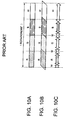
- a typical color wheel of a conventional projector has circularly arranged color filters of red (R), green (G), blue (B) and white (W).
- the projector drives the color wheel to rotate, thus lights from a light source are divided into primary colors RGB as shown in Fig. 10A .
- the divided primary color lights are output after time divisional processing.
- the output primary color lights are mixed at borders between the adjacent filters as shown in Fig. 10B .
- the conventional projectors usually perform display control with using the spatial light modulator.
- the conventional projector supplies RGB signal to the spatial light modulator in accordance with RGB components of the output luminous fluxes.
- the projector also supplies a white color signal as a brightness control signal to the spatial light modulator during the primary colors are mixed (color mixture term), to improve the brightness.
- the projector may supply a black color signal to the spatial light modulator during the color mixture term.
- the conventional projectors usually control lights through white regions.
- the control brings poor color reproduction performance because the RGB regions effecting for hue are reduced.
- Such the conventional projector having a white segment on a color wheel usually enhances white portions more than enough, thus the colors of projected images become dull.
- WO 2004/102245 A discloses a sequential illumination system having the features of the preamble of claim 1.
- US 6567134 B discloses a method and system for increasing the intensity of secondary colors in sequential color display systems. Secondary colors are provided to a SLM during a spoke period between adjacent primary color segments. The spoke period can be prolonged by arranging an additional secondary filter segment between primary filter segments. The secondary color is then provided to the SLM during the whole spoke period, including the time when the filtered light has the secondary color:
- WO 2005/019909 A discloses a device and method for spoke recovery in a sequential multi-primary color display, comprising a filter wheel with up to 5 primary filter segments.
- a primary color image component may be produced during at least a portion of a spoke period of a first primary color and a second primary color.>
- an object of the present invention is to provide a projector which is able to improve color reproduction performance.
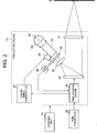
- Fig. 1 is a block diagram exemplifying the structure of a projector 1 according to the present embodiment.
- the projector 1 is designed to project images onto a screen 2, and comprises a data processor 11, a speaker 12, a projector engine 13, and control unit 14.
- the data processor 11 mainly performs data processing onto supplied image data to generate image data of images to be projected to the screen 2.
- the data processor 11 also performs data processing onto supplied audio data to generate audio signals to be output.
- Such the data processor 11 further comprises an input/output (I/O) interface 21, an image processor 22, an image memory 23, an audio processor 24, a video RAM 25, and an RGB converter 26.
- the I/O interface 21 inputs and/or outputs the image data and/or the audio data.
- the image processor 22 converts the supplied image data into predetermined formatted data.
- the image processor 22 also performs image processing such as keystone collection based on data representing slant angle of the screen 2.
- the angle data may be supplied to the image processor 22 from the control unit 14.
- the image memory 23 may be comprised of a flash memory and the like to store image data after image processing by the image processor 22, and the like.
- the audio processor 24 may comprises a sound circuit such as a PCM sound source to convert supplied audio data into analog signals to be output by the speaker 12.
- a sound circuit such as a PCM sound source to convert supplied audio data into analog signals to be output by the speaker 12.
- the video RAM 25 is prepared for developing the image data.
- the RGB converter 26 converts the image data into RGB signals after developing the supplied image data in the video RAM 25.
- the RGB converter supplies the generated RGB signals to the projector engine 13.
- the speaker 12 outputs sounds based on the audio signals supplied from the audio processor 24 in the data processor 11.
- the projector engine 13 is a core component of the projector 1 which project images based on the image data supplied from the data processor 11. As shown in Fig. 2 , the projector engine 13 comprises a spatial light modulator 31, a lamp 32, a reflector 33, a mirror tube 34, a color wheel 35, a color wheel motor 36, a color wheel controller 37, an optical sensor 38, a time division driver 39, a light source lens 40, and a projection lens 41.
- the spatial light modulator 31 comprises multiple micro mirrors (not shown).
- the micro mirrors are made of, for example, minute aluminum pieces each size is about 10 to 20 ⁇ m, and these reflect lights.
- the micro mirrors are matrix arrayed and driven by the time division driver 39.
- Each of the micro mirrors are driven to be slant, thus reflect output lights from the color wheel toward the screen 2.
- the lamp 32 emits white color lights as a light source.
- the reflector 33 reflects the lights emitted by the lamp 32 toward the mirror tube 34.
- the mirror tube 34 leads the white color lights emitted by the lamp 32 to the color wheel 35 with reflecting the lights at its inner surface so as to equalize the light distribution.
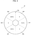
- the color wheel 35 has a plurality of primary color filters and a plurality of intermediate color filters. These filters are transparent colored filters, thus the lights from the lamp 32 penetrate through these color filters.
- the primary color filters are designed to divide the output lights into primary color lights.
- Each of the intermediate color filters comprises an intermediate colored filter whose color is intermediate between the adjacent primary colored filters.
- the color wheel 35 shows a circular shape, and 6 color filters (a filter 35R for red, a filter 35Y for yellow, a filter 35G for green, a filter 35C for cyan, a filter 35B for blue, and a filter 35M for magenta) are arranged in a circular direction.
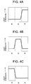
- the filters 35R, 35G, and 35B are the primary color filters for dividing the lights into the primary colors red (R), green (G) and blue (B) each having the spectral properties shown in Figs. 4A to 4C .
- Those primary color filters 35R, 35G, and 35B are arranged equally each having the equal angle at center of the color wheel 35. In this embodiment, the angle may be 60 degrees.
- the filter 35Y is one of the intermediate colored filters which is arranged between the green filter 35G and the red filter 35R.
- the filter 35Y is colored by yellow (Y) which is a complementary color between green and red (G+R) of the adjacent filters 35G and 35R.
- the filter 35C is another intermediate colored filter arranged between the green filter 35G and the blue filter 35B.
- the filter 35C is colored by cyan (C) which is a complementary color between green and blue (B+G) of the adjacent filters 35G and 35B.
- the filter 35M is also one of the intermediate color filters being arranged between the blue filter 35B and the red filter 35R.
- the filter 35M is colored by magenta (M) which is a complementary color between blue and red (R+B) of the adjacent filters 35B and 35R.
- the hole 35a is designed to detect positions of the color filters 35R, 35Y, 35G, 35C, 35B, and 35M.
- the color wheel motor 36 drives the color wheel 35 to rotate.
- the color wheel motor 36 rotates the color wheel 35 in the direction so that the lights from the lamp 32 penetrates the color filters on the color wheel 35 sequentially in order of red, yellow, green, cyan, blue, and magenta.
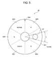
- the color wheel 35 thus rotates by the color wheel motor 36, and the lights from the lamp 32 go through the filters on the rotating color wheel 35.
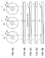
- a point where the lights go through the color wheel 35 is shown in Fig. 5 as a light spot SP.
- the size of the light spot SP is represented by angle ⁇ (see Fig. 5 ).
- Angle ⁇ is an angle between 2 straight lines both touching the circumference of the light spot SP while meeting at the center of the color wheel 35.
- the lights from the lamp 32 are divided into colored lights of red, yellow, green, cyan, blue or magenta when penetrating the color filters on the color wheel 35, and such the colored lights go toward the spatial light modulator 31 sequentially.
- the color wheel controller 37 controls the color wheel motor 36 to control rotation speed of the color wheel 35.
- Timing signals representing timings for synchronous with color signals (red, yellow, green, cyan, blue, and magenta) are supplied from the time division driver 39 to the color wheel controller 37.
- the color wheel controller 37 controls the color wheel motor 36 in accordance with the supplied timing signals.
- the photo sensor 38 may be comprised of photo couplers to detect positions of the color filters 35R, 35Y, 35G, 35C, 35B, and 35M.
- the photo sensor 38 detects the lights going through the hole 35a on the color wheel 35, and supplies detection signals to the time division driver 39.
- the time division driver 39 divides the RGB signals supplied from the RGB converter 26 in time sequence, thus generates primary color signals (a red color signal (R), a green color signal (G) and a blue color signal (B): RGB signals).
- the time division driver 39 drives the spatial light modulator 31 by supplying the divided RGB signals to the spatial light modulator 31.
- the time division driver 39 additionally generates a white color signal and intermediate color signals (a yellow color signal (Y), a magenta color signal (M) and a cyan color signal (C): YMC signals) by calculation based on the RGB signals supplied from the RGB converter 26.
- the time division driver 39 also divide those additional color signals in time sequence, and drives the spatial light modulator 31 by supplying those signals thereto.
- the time division driver 39 also obtains the detection signals from the photo sensor 38, thus obtains position of the light spot SP on the color wheel 35.
- the time division driver 39 supplies the divided RGB signals to the spatial light modulator 31 so as to correspond with the RGB colored lights divided by the primary color filters on the color wheel 35 during a term where the light spot SP is on the primary color filters 35R, 35G or 35B.
- the time division driver 39 supplies the divided YMC signals to the spatial light modulator 31 so as to correspond with the YMC colored lights divided by the intermediate color filters on the color wheel 35 during another term where the light spot SP is on the intermediate color filters 35Y, 35M or 35C.
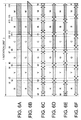
- Fig. 6A shows an order of the color filters according to a rotation of the color wheel 35.
- Fig. 6B shows changes of luminous fluxes according to a rotation of the color wheel 35.
- Fig. 6C shows changes of signals output by the time division driver 39 in a rotation of the color wheel 35 when the display control option 1 is performed.
- a term until time t1 from beginning represents a term where the lamp 32 emits lights toward the filter 35R of the color wheel 35 via the mirror tube 34, that is, the term where red colored luminous fluxes go toward the spatial light modulator 31 from the color wheel 35.
- terms each between t3 and t4, t6 and t7, t9 and t10, t12 and t13, and, t35 and t16 are terms where the luminous fluxes are colored by yellow, green, cyan, blue, and magenta respectively.
- terms each between t1 and t3, t4 and t6, t7 and t9, t10 and t12, and, t13 and t15 are color mixture terms each mixtures are red and yellow, yellow and green, green and cyan, cyan and blue, and, blue and magenta respectively.
- times t2, t5, t8, t11 and t14 are times at which two colors are mixed equally because the lights from the lamp 32 go through the 2 filters equally at those points.
- the display control option 1 is prepared for improving brightness of the projected images.
- the time division driver 39 controls the spatial light modulator 31 by supplying white color signals as the brightness control signal (hereinafter, referred to as "brightness signal W") thereto during the color mixture terms.
- the display control options 2 to 4 are prepared for enhancing hue.
- the option 2 is a display control for enhancing both the primary colors and the intermediate colors equally.
- the time division driver 39 controls the spatial light modulator 31 by supplying a color signal corresponding to color whose mixture rate is higher than that of the other mixed color during the color mixture terms.
- the display control option 3 is prepared for enhancing the intermediate colors.
- the time division driver 39 controls the spatial light modulator 31 by supplying intermediate color signals thereto during the color mixture terms.
- the display control option 4 is prepared for enhancing the primary colors.
- the time division driver 39 controls the spatial light modulator 31 by supplying primary color signals thereto during the color mixture terms.
- the time division driver 39 controls the spatial light modulator 31 with predetermined frame rate, for example, 30 frames per second.
- the light source lens 40 is a lens for gathering the lights from the color wheel 35 onto the spatial light modulator 31.
- the projection lens 41 is another lens for focusing the images by the lights from the spatial light modulator 31 onto the screen 2.
- the control unit 14 is a central controller of the projector 1 for controlling the most of the components in the projector 1.
- the control unit 14 may comprise a CPU, a ROM, a RAM, and the like (not shown).
- the CPU is a processor for controlling any components in the projector 1.
- the ROM is a memory device for storing programs to be executed by the CPU, and the like.
- the RAM is another memory device for storing data required for operations by the CPU, and the like.
- the control unit 14 controls the time division driver 39 in the projector engine 13 so that the time division driver 39 performs any one of the above display options 1 to 4.
- image data and audio data are supplied to the I/O interface 21.
- the audio processor 24 converts the supplied audio data into analog signals and outputs the audio signals to the speaker 12.
- the speaker 12 outputs sounds based on the supplied audio signals.
- the image processor 22 converts the supplied image data into predetermined formatted data, and stores them in the image memory 23.
- the RGB converter reads out the image data from the image memory 23, and develops them in the video RAM.
- the RGB converter converts the image data developed in the video RAM into RGB signals, and supplies the RGB signals to the projector engine 13.
- the time division driver 39 in the projector engine 13 performs calculation based on the supplied RGB signals to generate the brightness signal W. Then, the time division driver 39 divides the RGB signals and the brightness signal W in time sequence.
- the time division driver 39 also determines position of the color wheel 35 based on the detection signals supplied from the photo sensor 38.
- the control unit 14 controls the time division driver 39 to perform one of the display control options 1 to 4.
- control unit 14 controls the time division driver 39 to perform the display control option 1.
- the control unit 14 controls the time division driver 39 to perform the display control option 1.
- Fig 7A shows positions of the light spot SP at t1, t2 and t3 in the color mixture term of red and yellow.
- Fig. 7B shows changes of the color filters having the light spot SP during the term from t1 to t3.
- Fig. 7C shows changes of the luminous fluxes from the color wheel 35 during the term from t1 to t3.
- Fig. 7D shows changes of the signals output by the time division driver 39 during the term from t1 to t3.
- Fig. 7E shows changes of the projected lights during the term from t1 to t3.
- Fig 8A shows positions of the light spot SP at t4, t5 and t6 in the color mixture term of yellow and green.
- Fig. 8B shows changes of the color filters having the light spot SP during the term from t4 to t6.
- Fig. 8C shows changes of the luminous fluxes from the color wheel 35 during the term from t4 to t6.
- Fig. 8D shows changes of the signals output by the time division driver 39 during the term from t4 to t6.
- Fig. 8E shows changes of the projected lights during the term from t4 to t6.
- the time division driver 39 begins to control the spatial light modulator 31 by supplying the red color signal to the spatial light modulator 31 until time t1 (see Fig. 6C ).
- the time division driver 39 begins to supply the brightness signal W to the spatial light modulator 31 (see Fig. 6C and Fig. 7D ).
- red colored luminous fluxes from the color wheel 35 become weaker gradually, while yellow colored luminous fluxes become stronger gradually, as shown in Fig. 7C .
- the projected lights from the projector engine 13 show the same changes as that of the luminous fluxes as shown in Fig. 7E . That is, red colored projected lights become weaker gradually, while yellow colored projected lights become stronger gradually.
- the projected lights change to yellow from red smoothly even if red and yellow are mixed during the color mixture term. Moreover, the brightness of the projected images improves because the brightness signal is supplied to the spatial light modulator 31 during the color mixture term of red and yellow.
- the time division driver 39 supplies yellow color signals to the spatial light modulator 31 so as to correspond to the yellow colored lights from the color wheel 35 (see Fig. 7D ).
- the next color mixture term of yellow and green begins (see Fig. 6C and Fig. 8C ).
- the time division driver 39 begins to supply the brightness signal W to the spatial light modulator 31 (see Fig. 8D ).
- the projected lights shows mixed color of yellow and green, as shown in Fig. 8E .
- yellow is a composite color of red and green, as aforementioned, the color of the projected lights changes to green from yellow smoothly even if yellow and green are mixed during the color mixture term. Moreover, brightness of the projected image improves because the brightness signal W is supplied to the spatial light modulator 31 during the color mixture term of yellow and green.
- the color mixture term of yellow and green ends.
- the time division driver 39 continues to control the spatial light modulator 31 in the same manner for the other terms.
- the time division driver 39 supplies the green color signal to the spatial light modulator 31 (see Fig. 6C ).
- the next color mixture term begins at t7.
- the time division driver 39 supplies the brightness signal W to the spatial light modulator 31 (see Fig. 6C ).
- the time division driver 39 supplies cyan color signal to the spatial light modulator 31 (see Fig. 6C ).
- the next color mixture term of cyan and blue begins at t10.
- the time division driver 39 supplies the brightness signal W to the spatial light modulator 31 (see Fig. 6C ).
- the time division driver 39 supplies blue color signals to the spatial light modulator 31 (see Fig. 6C ).
- the time division driver 39 supplies the brightness signal W to the spatial light modulator 31 (see Fig. 6C ).
- the time division driver 39 supplies primary color signals during the primary color terms, intermediate color signals during the intermediate color terms, and brightness signals W during the color mixture terms, thus the brightness of the projected images improves.
- control unit 14 controls the time division driver 39 to execute one of the display control options 2 to 4.
- control unit 14 controls the time division driver 39 to perform display control option 2. Operations of the display control option 2, will now be described with reference to Fig. 6D .
- the time division driver 39 begins to control the spatial light modulator 31 by supplying the red color signal, because mixture rate of red is higher than that of yellow at beginning of the color mixture term of red and yellow.
- the time division driver 39 begins to supply yellow color signal (intermediate color) to the spatial light modulator 31.
- the time division driver 39 does not supply the brightness signal W to the spatial light modulator 31 during the color mixture term, thus hue is enhanced. Since yellow is a composite color of red and green, color of the projected images changes to green from red smoothly via yellow during the color mixture term. Since the primary color signals and the intermediate color signals are supplied equally during the color mixture term, both the primary colors and the intermediate colors are enhanced equally.
- the time division driver 39 controls the spatial light modulator 31 in the same manner by supplying corresponding primary and intermediate color signals during each of the color mixture terms (see Fig. 6D ), thus the other the primary colors (green, blue) and the intermediate color between them (cyan, magenta) will be enhanced equally as well.
- control unit 14 controls the time division driver 39 to execute display control option 3. Operations of the time division driver 39 for the display control option 3 will now be described with reference to Fig. 6E .
- the time division driver 39 begins to control the spatial light modulator 31 by supplying the yellow color signal (intermediate color) to the spatial light modulator 31.
- the time division driver 39 continues to supplied the yellow color signal to the spatial light modulator 31 during the intermediate color term of yellow (from t3 to t4) until the next color mixture term of yellow and green ends (from t4 to t6). Since the intermediate color signal is supplied during the color mixture term, the intermediate color is enhanced.
- the time division driver 39 controls the spatial light modulator 31 in the same manner by supplying corresponding intermediate color signals thereto during each of the color mixture terms (see Fig. 6E ), thus the other intermediate colors (cyan, magenta) will be enhanced as well.
- control unit 14 controls the time division driver 39 to execute display control option 4. Operations of the time division driver 39 for the display control option 4 will now be described with reference to Fig. 6F .
- the time division driver 39 begins to control the spatial light modulator 31 by supplying red color signal (primary color) to the spatial light modulator 31 during the color mixture term or red and yellow between t1 and t3.
- the time division driver 39 supplies yellow color signals (intermediate color) to the spatial light modulator 31. Since the primary color signal is supplied during the color mixture term, primary colors are enhanced.
- the time division driver 39 controls the spatial light modulator 31 in the same manner by supplying corresponding color signals thereto during each of the color mixture terms (see Fig. 6F ), thus the other primary colors (green, blue) will be enhanced as well.
- various display controls as described above are available, because it realizes fine intermediate color control being synchronous with the lights from the color wheel 35.
- the color wheel 35 of this embodiment according to the present invention has the intermediate color filters in addition to the primary color filters, that is, the color wheel 35 is 6-segment color wheel. Even if such the 6-segment structure, it realizes highly improved brightness as the same as the conventional 4-segment structure.
- the brightness value of the projector 1 according to the embodiment is equal to the brightness value of the conventional projector.
- the RGB primary color filters 35R, 35G and 35B are arranged equally in the color wheel 35, and the complementary color filters 35C, 35M and 35Y of typical intermediate colors are arranged between each adjacent primary color filters.
- the color wheel 35 has the 6-segment structure with 6 color filters.
- the number of segments (colors) is not limited to 6, for example, each of the intermediate color filters has a plurality of filters in accordance with gradation of the intermediate color.
- the above embodiment just showed an example of a color wheel according to the present invention.
- the color wheel must have equally arranged segments each angle at the wheel center is 60 degrees.
- the present invention may be applicable even if the color wheel has unequally arranged segments.
- the present invention may be applicable to a case where a color wheel has RGB segments having 90 degrees center angle for each, while each of YMC segments is 30 degrees.
- Brightness value resultant from such the unequally arranged segments differs from the brightness value example described above. However, it results better hue rather than a case where a color wheel has a W (white) segment instead of the YMC segments, and projected images are brighter rather than a case where a color wheel has only RGB segments.
- the time division driver 39 supplies the white color signals as the brightness control signal to the spatial light modulator 31 during the color mixture terms when it executes display control option 1 in the above embodiment, the time division driver 39 may supply black color signals to the spatial light modulator 31 during the color mixture terms for controlling brightness or hue.
- the present invention may be applicable to various projectors such as a film projector for movie films or still picture films.
Landscapes
- Engineering & Computer Science (AREA)
- Multimedia (AREA)
- Signal Processing (AREA)
- Physics & Mathematics (AREA)
- General Physics & Mathematics (AREA)
- Optics & Photonics (AREA)
- Projection Apparatus (AREA)
- Video Image Reproduction Devices For Color Tv Systems (AREA)
- Devices For Indicating Variable Information By Combining Individual Elements (AREA)
Claims (5)
- Projektor zur Projektion von Bildern auf ein Projektionselement, umfassend:eine Lichtquelle (32), die zum Aussenden von weißem Licht gestaltet ist;eine Filtereinheit (35), die Primärfarbfilter für Rot (R), Grün (G) und Blau (B) sowie Sekundärfarbfilter für Gelb (Y), Cyan (C) und Magenta (M) zur Zerlegung des weißen Lichts aus der Lichtquelle (32) in eine Vielzahl von Primärfarblichtern bzw. Sekundärfarblichtern aufweist, wobei die Primärfarbfilter und Sekundärfarbfilter in der Reihenfolge von Rot, Gelb, Grün, Cyan, Blau und Magenta angeordnet sind;einen räumlichen Lichtmodulator (31), der gesteuert wird, das durch die Filtereinheit (35) zerlegte Farblicht auf das Projektionselement zu projizieren, um die Bilder zu projizieren; undeinen Display treiber (39), dem eine Vielzahl von Primärfarbsignalen zum Erzeugen der auf das Projektionselement zu projizierenden Bilder zugeführt wird, der gestaltet ist, ein weißes Farbsignal und Sekundärfarbsignale basierend auf den zugeführten Primärfarbsignalen zu erzeugen, und gestaltet ist, den räumlichen Lichtmodulator (31) zu steuern, indem die Primärfarbsignale dem räumlichen Lichtmodulator (31) zugeführt werden, so dass Primärfarben der zugeführten Primärfarbsignale Primärfarblichtern aus der Filtereinheit (35) entsprechen, und indem die erzeugten Sekundärfarbsignale dem räumlichen Lichtmodulator (31) zugeführt werden, so dass Sekundärfarben der erzeugten Sekundärfarbsignale Sekundärfarblichtern aus der Filtereinheit (35) entsprechen,wobeider Display treiber (39) gestaltet ist, eine von einer ersten Displaysteueroption, einer zweiten Displaysteueroption, einer dritten Displaysteueroption und einer vierten Displaysteueroption bei Bedingungen auszuführen, wenn das durch die Filtereinheit (35) zerlegte Licht eine Farbmischung einer Primär- und einer Sekundärfarbe ist;wobei in der ersten Displaysteueroption das erzeugte weiße Farbsignal dem räumlichen Lichtmodulator (31) zugeführt wird;wobei in der dritten Displaysteueroption das der Sekundärfarbe der Farbmischung entsprechende, erzeugte Sekundärfarbsignal dem räumlichen Lichtmodulator (31) zugeführt wird;wobei in der zweiten Displaysteueroption dem räumlichen Lichtmodulator (31) das der Primärfarbe der Farbmischung entsprechende, zugeführte Primärfarbsignal zugeführt wird, wenn das Mischungsverhältnis der Primärfarbe höher ist als das der Sekundärfarbe, und das der Sekundärfarbe der Farbmischung entsprechende, erzeugte Sekundärfarbsignal zugeführt wird, wenn das Mischungsverhältnis der Sekundärfarbe höher ist als das der Primärfarbe; undwobei in der vierten Displaysteueroption das der Primärfarbe der Farbmischung entsprechende, zugeführte Primärfarbsignal dem räumlichen Lichtmodulator (31) zugeführt wird.
- Verfahren zur Steuerung eines räumlichen Lichtmodulators in einem Projektor nach Anspruch 1, umfassend die Schritte:Erhalten einer Vielzahl von Primärfarbsignalen zur Erzeugung von auf das Projektionselement zu projizierenden Bildern;Zuführen der Primärfarbsignale dem räumlichen Lichtmodulator (31), so dass Primärfarben der erhaltenen Primärfarbsignale den Primärfarblichtern aus der Filtereinheit (35) entsprechen;Erzeugen eines weißen Farbsignals und von Sekundärfarbsignalen basierend auf den erhaltenen Primärfarbsignalen; undZuführen der Sekundärfarbsignale dem räumlichen Lichtmodulator (31), so dass Sekundärfarben der zugeführten Sekundärfarbsignale Sekundärfarblichtern aus der Filtereinheit (35) entsprechen,Ausführen einer von einer ersten Displaysteueroption, einer zweiten Displaysteueroption, einer dritten Displaysteueroption und einer vierten Displaysteueroption bei Bedingungen, wenn das durch die Filtereinheit (35) zerlegte Licht eine Farbmischung einer Primär- und einer Sekundärfarbe ist;wobei in der ersten Displaysteueroption das erzeugte weiße Farbsignal dem räumlichen Lichtmodulator (31) zugeführt wird;wobei in der zweiten Displaysteueroption dem räumlichen Lichtmodulator (31) das der Primärfarbe der Farbmischung entsprechende, zugeführte Primärfarbsignal zugeführt wird, wenn das Mischungsverhältnis der Primärfarbe höher ist als das der Sekundärfarbe; und das der Sekundärfarbe der Farbmischung entsprechende, erzeugte Sekundärfarbsignal zugeführt wird, wenn das Mischungsverhältnis der Sekundärfarbe höher ist als das der Primärfarbe;wobei in der dritten Displaysteueroption das der Sekundärfarbe der Farbmischung entsprechende, erzeugte Sekundärfarbsignal dem räumlichen Lichtmodulator (31) zugeführt wird; undwobei in der vierten Displaysteueroption das der Primärfarbe der Farbmischung entsprechende, zugeführte Primärfarbsignal dem räumlichen Lichtmodulator (31) zugeführt wird.
- Computerlesbares Programm, umfassend Computerprogrammcodemittel, die gestaltet sind, alle Schritte des Verfahrens nach Anspruch 2 durchzuführen, wenn das Programm auf einem Computer abläuft.
- Projektor nach Anspruch 1, wobei der Displaytreiber ein Zeitverschachtelungstreiber ist, der gestaltet ist, umin der Art und Weise einer Zeitverschachtelung die Primärfarbsignale und die Sekundärfarbsignale zu dem räumlichen Lichtmodulator (31) zu übertragen, so dass der räumliche Lichtmodulator (31) Lichter aus der Filtereinheit (35) zum Projizieren von Bildern auf das Projektionselement moduliert; unddes Weiteren gestaltet ist, die Filtereinheit (35) zu steuern, indem Steuersignale der Filtereinheit (35) zugeführt werden, so dass Lichter aus der Filtereinheit (35) mit Farben, die den Primärfarbsignalen und den Sekundärfarbsignalen entsprechen, der räumlichen Lichtmodulation (31) zugeführt werden.
- Projektor nach Anspruch 1, wobei der räumliche Lichtmodulator gestaltet ist, in der Art und Weise einer Zeitverschachtelung Steuersignale zu empfangen, die von dem Displaytreiber (39) einschließlich Signalen zugeführt werden, die nicht nur auf Primärfarben sondern auch auf Sekundärfarben basieren; undaußerdem gestaltet ist, Lichter zu modulieren, deren Farben in der Art und Weise einer Zeitverschachtelung basierend auf den empfangenen Steuersignalen verändert sind.
Applications Claiming Priority (2)
| Application Number | Priority Date | Filing Date | Title |
|---|---|---|---|
| JP2005089624A JP4285428B2 (ja) | 2005-03-25 | 2005-03-25 | 投影装置 |
| PCT/JP2006/307000 WO2006101277A1 (en) | 2005-03-25 | 2006-03-27 | Projector, method for controlling a spatial light modulator, and program for controlling the same |
Publications (2)
| Publication Number | Publication Date |
|---|---|
| EP1862015A1 EP1862015A1 (de) | 2007-12-05 |
| EP1862015B1 true EP1862015B1 (de) | 2016-11-02 |
Family
ID=36337576
Family Applications (1)
| Application Number | Title | Priority Date | Filing Date |
|---|---|---|---|
| EP06730948.4A Ceased EP1862015B1 (de) | 2005-03-25 | 2006-03-27 | Projektor, verfahren zur steuerung eines räumlichen lichtmodulators und programm zu dessen steuerung |
Country Status (7)
| Country | Link |
|---|---|
| US (1) | US7665851B2 (de) |
| EP (1) | EP1862015B1 (de) |
| JP (1) | JP4285428B2 (de) |
| KR (2) | KR100904814B1 (de) |
| CN (1) | CN101147403A (de) |
| TW (1) | TWI341954B (de) |
| WO (1) | WO2006101277A1 (de) |
Families Citing this family (11)
| Publication number | Priority date | Publication date | Assignee | Title |
|---|---|---|---|---|
| US7760173B2 (en) * | 2005-07-11 | 2010-07-20 | Casio Computer Co., Ltd. | Projection display apparatus having image modulation timing changing function |
| KR100818985B1 (ko) * | 2006-08-10 | 2008-04-04 | 삼성전자주식회사 | 영상 보정 장치 및 방법 |
| US8061874B2 (en) | 2007-05-21 | 2011-11-22 | Production Resource Group, L.L.C. | Light coloring system |
| JP2009092745A (ja) * | 2007-10-04 | 2009-04-30 | Necディスプレイソリューションズ株式会社 | 映像表示装置及びその光源駆動方法 |
| JP5241356B2 (ja) * | 2008-07-11 | 2013-07-17 | 三菱電機株式会社 | 投射型映像装置 |
| KR101597822B1 (ko) * | 2008-11-25 | 2016-02-25 | 삼성전자주식회사 | 프로젝터의 색온도 조절 방법 |
| JP5674757B2 (ja) | 2009-03-17 | 2015-02-25 | コーニンクレッカ フィリップス エヌ ヴェ | カラーシーケンシャルディスプレイを駆動する方法 |
| JP5494610B2 (ja) * | 2011-10-17 | 2014-05-21 | カシオ計算機株式会社 | 投影装置、投影制御方法及びプログラム |
| JP6161804B2 (ja) * | 2013-06-07 | 2017-07-12 | アポトロニクス コーポレイション リミテッド | カラーホイールアッセンブリ及びその関連する光源システム |
| CN104930453A (zh) * | 2015-06-16 | 2015-09-23 | 广州彩熠灯光有限公司 | 便于定位的舞台灯具 |
| CN118838106A (zh) * | 2023-04-24 | 2024-10-25 | 昆山扬皓光电有限公司 | 色轮系统及色轮控制方法 |
Family Cites Families (15)
| Publication number | Priority date | Publication date | Assignee | Title |
|---|---|---|---|---|
| US6147720A (en) * | 1995-12-27 | 2000-11-14 | Philips Electronics North America Corporation | Two lamp, single light valve projection system |
| JPH11264953A (ja) | 1998-03-17 | 1999-09-28 | Minolta Co Ltd | カラー投影装置 |
| WO2000033288A1 (en) * | 1998-12-01 | 2000-06-08 | Seiko Epson Corporation | Color display device and color display method |
| US6324006B1 (en) * | 1999-05-17 | 2001-11-27 | Texas Instruments Incorporated | Spoke light recapture in sequential color imaging systems |
| US6567134B1 (en) * | 1999-06-08 | 2003-05-20 | Texas Instruments Incorporated | Secondary color boost in sequential color systems |
| US6771325B1 (en) * | 1999-11-05 | 2004-08-03 | Texas Instruments Incorporated | Color recapture for display systems |
| JP2002006395A (ja) * | 2000-06-26 | 2002-01-09 | Canon Inc | 画像表示装置 |
| US6726333B2 (en) * | 2001-02-09 | 2004-04-27 | Reflectivity, Inc | Projection display with multiply filtered light |
| JP4085723B2 (ja) | 2002-07-15 | 2008-05-14 | カシオ計算機株式会社 | 投影型表示装置及びその表示駆動方法 |
| JP3853730B2 (ja) | 2002-12-25 | 2006-12-06 | Necビューテクノロジー株式会社 | カラー画像表示装置の画像調整方法およびカラー画像表示装置 |
| JP4009542B2 (ja) | 2003-02-10 | 2007-11-14 | Necディスプレイソリューションズ株式会社 | 時分割映像表示方法及び装置並びにカラーホイール組立体 |
| FR2854698A1 (fr) * | 2003-05-09 | 2004-11-12 | Thomson Licensing Sa | Systeme de projection d'images a un seul imageur dote d'une roue coloree ayant plusieurs sous-ensembles de segments colores |
| FR2857814A1 (fr) | 2003-07-17 | 2005-01-21 | Thomson Licensing Sa | DISPOSITIF d'AFFICHAGE D'IMAGES EN COULEURS |
| WO2005019909A2 (en) | 2003-08-26 | 2005-03-03 | Genoa Color Technologies Ltd. | Spoke recovery in a color display |
| US7760173B2 (en) * | 2005-07-11 | 2010-07-20 | Casio Computer Co., Ltd. | Projection display apparatus having image modulation timing changing function |
-
2005
- 2005-03-25 JP JP2005089624A patent/JP4285428B2/ja not_active Expired - Lifetime
-
2006
- 2006-03-23 US US11/387,341 patent/US7665851B2/en active Active
- 2006-03-24 TW TW095110186A patent/TWI341954B/zh not_active IP Right Cessation
- 2006-03-27 KR KR1020077016387A patent/KR100904814B1/ko not_active Expired - Fee Related
- 2006-03-27 KR KR1020097007182A patent/KR100907593B1/ko not_active Expired - Fee Related
- 2006-03-27 CN CNA2006800097208A patent/CN101147403A/zh active Pending
- 2006-03-27 EP EP06730948.4A patent/EP1862015B1/de not_active Ceased
- 2006-03-27 WO PCT/JP2006/307000 patent/WO2006101277A1/en not_active Ceased
Also Published As
| Publication number | Publication date |
|---|---|
| EP1862015A1 (de) | 2007-12-05 |
| KR100907593B1 (ko) | 2009-07-14 |
| US20060215128A1 (en) | 2006-09-28 |
| TW200702879A (en) | 2007-01-16 |
| WO2006101277A1 (en) | 2006-09-28 |
| CN101147403A (zh) | 2008-03-19 |
| JP4285428B2 (ja) | 2009-06-24 |
| TWI341954B (en) | 2011-05-11 |
| US7665851B2 (en) | 2010-02-23 |
| JP2006267926A (ja) | 2006-10-05 |
| KR20090043609A (ko) | 2009-05-06 |
| KR20070087138A (ko) | 2007-08-27 |
| KR100904814B1 (ko) | 2009-06-25 |
Similar Documents
| Publication | Publication Date | Title |
|---|---|---|
| EP2942946B1 (de) | Lichtquellenvorrichtung, Videoprojektor und Videoprojektionsverfahren | |
| JP6565846B2 (ja) | 光源装置及び投影装置 | |
| KR100936836B1 (ko) | 프로젝터, 프로젝터 시스템, 및 프로그램을 기록한 컴퓨터 판독 가능한 기록 매체 | |
| JP6583664B2 (ja) | 光源装置及び投影装置 | |
| US20150253653A1 (en) | Illumination device, projector, and illumination method | |
| EP1862015B1 (de) | Projektor, verfahren zur steuerung eines räumlichen lichtmodulators und programm zu dessen steuerung | |
| JP2004333758A (ja) | 表示装置、及び表示方法、並びにプロジェクタ | |
| EP3474545B1 (de) | Projektor und projektionsverfahren | |
| JP2005266324A (ja) | 投射光学装置および投射型画像表示装置 | |
| JP2002287247A (ja) | 色分離合成光学系およびプロジェクタ | |
| EP3025324B1 (de) | Informationsverarbeitungsvorrichtung, bildprojektionssystem und computerprogramm | |
| JP2006510927A (ja) | 4つの原色を有するカラー順次投射型システム | |
| CN111812930B (zh) | 投影装置、投影控制装置以及记录介质 | |
| JP2008181116A (ja) | カラー画像を表示するための画像化システム、画像化システムを制御するためのコントローラ、カラー画像を画像化するための画像化セットアップ、およびカラー画像を画像化するための方法 | |
| JP4757534B2 (ja) | カラーリング切り替え機構を有する画像表示装置とカラーホイール制御方法 | |
| JP4983767B2 (ja) | 投影装置 | |
| JP5446355B2 (ja) | 表示装置、画像表示制御プログラム及び画像表示方法 | |
| JP2005043704A (ja) | カラー表示装置 | |
| JP2007133094A (ja) | プロジェクタ及び光調整方法 | |
| JP2005167680A (ja) | プロジェクタシステム | |
| JP7054458B2 (ja) | 投影装置、投影制御方法及びプログラム | |
| CN101191987B (zh) | 照明装置及投影型图像显示装置 | |
| HK1178260B (en) | Projection apparatus, and projection method | |
| HK1178260A1 (en) | Projection apparatus, and projection method | |
| JP2009134018A (ja) | 映像信号変換装置及び映像表示装置 |
Legal Events
| Date | Code | Title | Description |
|---|---|---|---|
| PUAI | Public reference made under article 153(3) epc to a published international application that has entered the european phase |
Free format text: ORIGINAL CODE: 0009012 |
|
| 17P | Request for examination filed |
Effective date: 20070615 |
|
| AK | Designated contracting states |
Kind code of ref document: A1 Designated state(s): DE FR GB |
|
| DAX | Request for extension of the european patent (deleted) | ||
| RBV | Designated contracting states (corrected) |
Designated state(s): DE FR GB |
|
| 17Q | First examination report despatched |
Effective date: 20080806 |
|
| GRAP | Despatch of communication of intention to grant a patent |
Free format text: ORIGINAL CODE: EPIDOSNIGR1 |
|
| INTG | Intention to grant announced |
Effective date: 20160629 |
|
| GRAS | Grant fee paid |
Free format text: ORIGINAL CODE: EPIDOSNIGR3 |
|
| GRAA | (expected) grant |
Free format text: ORIGINAL CODE: 0009210 |
|
| AK | Designated contracting states |
Kind code of ref document: B1 Designated state(s): DE FR GB |
|
| REG | Reference to a national code |
Ref country code: GB Ref legal event code: FG4D |
|
| REG | Reference to a national code |
Ref country code: DE Ref legal event code: R096 Ref document number: 602006050753 Country of ref document: DE |
|
| REG | Reference to a national code |
Ref country code: FR Ref legal event code: PLFP Year of fee payment: 12 |
|
| REG | Reference to a national code |
Ref country code: DE Ref legal event code: R097 Ref document number: 602006050753 Country of ref document: DE |
|
| PLBE | No opposition filed within time limit |
Free format text: ORIGINAL CODE: 0009261 |
|
| STAA | Information on the status of an ep patent application or granted ep patent |
Free format text: STATUS: NO OPPOSITION FILED WITHIN TIME LIMIT |
|
| 26N | No opposition filed |
Effective date: 20170803 |
|
| REG | Reference to a national code |
Ref country code: FR Ref legal event code: PLFP Year of fee payment: 13 |
|
| PGFP | Annual fee paid to national office [announced via postgrant information from national office to epo] |
Ref country code: FR Payment date: 20210210 Year of fee payment: 16 |
|
| PGFP | Annual fee paid to national office [announced via postgrant information from national office to epo] |
Ref country code: DE Payment date: 20210316 Year of fee payment: 16 Ref country code: GB Payment date: 20210318 Year of fee payment: 16 |
|
| REG | Reference to a national code |
Ref country code: DE Ref legal event code: R119 Ref document number: 602006050753 Country of ref document: DE |
|
| GBPC | Gb: european patent ceased through non-payment of renewal fee |
Effective date: 20220327 |
|
| PG25 | Lapsed in a contracting state [announced via postgrant information from national office to epo] |
Ref country code: GB Free format text: LAPSE BECAUSE OF NON-PAYMENT OF DUE FEES Effective date: 20220327 Ref country code: FR Free format text: LAPSE BECAUSE OF NON-PAYMENT OF DUE FEES Effective date: 20220331 Ref country code: DE Free format text: LAPSE BECAUSE OF NON-PAYMENT OF DUE FEES Effective date: 20221001 |