EP1858648B1 - Druckluft-drosselvorrichtung und pulversprühbeschichtungsvorrichtung - Google Patents
Druckluft-drosselvorrichtung und pulversprühbeschichtungsvorrichtung Download PDFInfo
- Publication number
- EP1858648B1 EP1858648B1 EP20060710394 EP06710394A EP1858648B1 EP 1858648 B1 EP1858648 B1 EP 1858648B1 EP 20060710394 EP20060710394 EP 20060710394 EP 06710394 A EP06710394 A EP 06710394A EP 1858648 B1 EP1858648 B1 EP 1858648B1
- Authority
- EP
- European Patent Office
- Prior art keywords
- throttle
- valve
- compressed air
- air
- powder
- Prior art date
- Legal status (The legal status is an assumption and is not a legal conclusion. Google has not performed a legal analysis and makes no representation as to the accuracy of the status listed.)
- Expired - Lifetime
Links
Images


Classifications
-
- B—PERFORMING OPERATIONS; TRANSPORTING
- B05—SPRAYING OR ATOMISING IN GENERAL; APPLYING FLUENT MATERIALS TO SURFACES, IN GENERAL
- B05B—SPRAYING APPARATUS; ATOMISING APPARATUS; NOZZLES
- B05B7/00—Spraying apparatus for discharge of liquids or other fluent materials from two or more sources, e.g. of liquid and air, of powder and gas
- B05B7/14—Spraying apparatus for discharge of liquids or other fluent materials from two or more sources, e.g. of liquid and air, of powder and gas designed for spraying particulate materials
- B05B7/1404—Arrangements for supplying particulate material
-
- B—PERFORMING OPERATIONS; TRANSPORTING
- B05—SPRAYING OR ATOMISING IN GENERAL; APPLYING FLUENT MATERIALS TO SURFACES, IN GENERAL
- B05B—SPRAYING APPARATUS; ATOMISING APPARATUS; NOZZLES
- B05B12/00—Arrangements for controlling delivery; Arrangements for controlling the spray area
- B05B12/08—Arrangements for controlling delivery; Arrangements for controlling the spray area responsive to condition of liquid or other fluent material to be discharged, of ambient medium or of target ; responsive to condition of spray devices or of supply means, e.g. pipes, pumps or their drive means
- B05B12/085—Arrangements for controlling delivery; Arrangements for controlling the spray area responsive to condition of liquid or other fluent material to be discharged, of ambient medium or of target ; responsive to condition of spray devices or of supply means, e.g. pipes, pumps or their drive means responsive to flow or pressure of liquid or other fluent material to be discharged
-
- B—PERFORMING OPERATIONS; TRANSPORTING
- B05—SPRAYING OR ATOMISING IN GENERAL; APPLYING FLUENT MATERIALS TO SURFACES, IN GENERAL
- B05B—SPRAYING APPARATUS; ATOMISING APPARATUS; NOZZLES
- B05B5/00—Electrostatic spraying apparatus; Spraying apparatus with means for charging the spray electrically; Apparatus for spraying liquids or other fluent materials by other electric means
- B05B5/025—Discharge apparatus, e.g. electrostatic spray guns
- B05B5/053—Arrangements for supplying power, e.g. charging power
- B05B5/0533—Electrodes specially adapted therefor; Arrangements of electrodes
-
- B—PERFORMING OPERATIONS; TRANSPORTING
- B05—SPRAYING OR ATOMISING IN GENERAL; APPLYING FLUENT MATERIALS TO SURFACES, IN GENERAL
- B05B—SPRAYING APPARATUS; ATOMISING APPARATUS; NOZZLES
- B05B5/00—Electrostatic spraying apparatus; Spraying apparatus with means for charging the spray electrically; Apparatus for spraying liquids or other fluent materials by other electric means
- B05B5/16—Arrangements for supplying liquids or other fluent material
-
- B—PERFORMING OPERATIONS; TRANSPORTING
- B05—SPRAYING OR ATOMISING IN GENERAL; APPLYING FLUENT MATERIALS TO SURFACES, IN GENERAL
- B05B—SPRAYING APPARATUS; ATOMISING APPARATUS; NOZZLES
- B05B7/00—Spraying apparatus for discharge of liquids or other fluent materials from two or more sources, e.g. of liquid and air, of powder and gas
- B05B7/14—Spraying apparatus for discharge of liquids or other fluent materials from two or more sources, e.g. of liquid and air, of powder and gas designed for spraying particulate materials
- B05B7/1404—Arrangements for supplying particulate material
- B05B7/1472—Powder extracted from a powder container in a direction substantially opposite to gravity by a suction device dipped into the powder
-
- Y—GENERAL TAGGING OF NEW TECHNOLOGICAL DEVELOPMENTS; GENERAL TAGGING OF CROSS-SECTIONAL TECHNOLOGIES SPANNING OVER SEVERAL SECTIONS OF THE IPC; TECHNICAL SUBJECTS COVERED BY FORMER USPC CROSS-REFERENCE ART COLLECTIONS [XRACs] AND DIGESTS
- Y10—TECHNICAL SUBJECTS COVERED BY FORMER USPC
- Y10T—TECHNICAL SUBJECTS COVERED BY FORMER US CLASSIFICATION
- Y10T137/00—Fluid handling
- Y10T137/8158—With indicator, register, recorder, alarm or inspection means
- Y10T137/8225—Position or extent of motion indicator
- Y10T137/8242—Electrical
-
- Y—GENERAL TAGGING OF NEW TECHNOLOGICAL DEVELOPMENTS; GENERAL TAGGING OF CROSS-SECTIONAL TECHNOLOGIES SPANNING OVER SEVERAL SECTIONS OF THE IPC; TECHNICAL SUBJECTS COVERED BY FORMER USPC CROSS-REFERENCE ART COLLECTIONS [XRACs] AND DIGESTS
- Y10—TECHNICAL SUBJECTS COVERED BY FORMER USPC
- Y10T—TECHNICAL SUBJECTS COVERED BY FORMER US CLASSIFICATION
- Y10T137/00—Fluid handling
- Y10T137/8158—With indicator, register, recorder, alarm or inspection means
- Y10T137/8225—Position or extent of motion indicator
- Y10T137/8275—Indicator element rigidly carried by the movable element whose position is indicated
-
- Y—GENERAL TAGGING OF NEW TECHNOLOGICAL DEVELOPMENTS; GENERAL TAGGING OF CROSS-SECTIONAL TECHNOLOGIES SPANNING OVER SEVERAL SECTIONS OF THE IPC; TECHNICAL SUBJECTS COVERED BY FORMER USPC CROSS-REFERENCE ART COLLECTIONS [XRACs] AND DIGESTS
- Y10—TECHNICAL SUBJECTS COVERED BY FORMER USPC
- Y10T—TECHNICAL SUBJECTS COVERED BY FORMER US CLASSIFICATION
- Y10T137/00—Fluid handling
- Y10T137/8593—Systems
- Y10T137/86493—Multi-way valve unit
- Y10T137/86509—Sequentially progressive opening or closing of plural ports
- Y10T137/86517—With subsequent closing of first port
Definitions
- the invention relates to a compressed air throttle apparatus, in particular for powder spray coating apparatus, according to the preamble of claim 1. Furthermore, the invention relates to a powder spray coating apparatus which includes at least one such throttle device.
- a powder spray coating apparatus with a throttle device of this kind is known from US 5,156,237 EP 1 156 882 B1 known. It contains an electric stepper motor which rotates a valve member via a bellows coupling.
- the valve member has a thread which engages a housing thread, so that the valve member is also axially displaced during its rotation relative to a valve seat to adjust the opening width of a throttle valve provided in the valve seat.
- the patent also shows a throttle device with two throttle valves, which are arranged opposite to each other and are driven by the same stepper motor, so that at an opening movement at one throttle valve, the other throttle valve performs a closing movement, or vice versa, depending on the direction of rotation of the stepping motor.
- the stepping motor is rotated from a reference position by a certain number of steps.
- the throttle valve in the reference position the smallest opening cross-section, which latter may either be completely closed or may be slightly open for a compressed air leakage current, which is measured before the start of the throttle device and the electrical control of the stepping motor is taken into account for setting a desired operating compressed air flow.
- FIG. 1 The drawings attached hereto show a known from practice embodiment of a powder spray coating apparatus according to said EP 1 156 882 B1 ,
- An electric stepping motor 2 is driven by an electric control device, not shown, to rotate about a bellows 4 a valve member 6 by a predetermined number of rotation steps, thereby adjusting a valve needle head 8 of the valve member 6 relative to a valve seat 10 and thereby the opening width of a set in the valve seat 10 formed throttle channel 12.
- the valve member 6 is provided with a thread 14 which engages in a thread 16 of a housing 17, so that the rotational movement of the stepping motor 2 is converted into an axial movement of the valve member 6.
- the throttle channel 12 can be opened by more than a single turn of 360 ° of the valve member 6, the two stops 18 and 20 already shortly before a complete revolution of 360 ° again as far axially distance accordingly FIG. 1 have from each other that they can be moved past each other in the direction of rotation are.
- the problem to be solved is to provide a possibility by which fine adjustments of the throttle device are possible in a simpler manner than in the prior art.
- the invention is useful not only for powder coating apparatus, but also for all other applications where fine adjustments of compressed air streams or liquid streams are required.
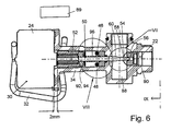
- the compressed air throttle device 21 which in the FIGS. 2 to 9 includes a throttle valve 22 and a controllable electric motor 24 with a motor shaft 26 for adjusting the throttle valve 22.
- the motor 24 may be any type of engine, the motor shaft 26 is controlled to defined rotational angle positions adjustable. It is preferably an electric stepper motor.
- the motor housing 30 of the electric motor 24 is held by a spring clip 32 to a valve housing 34.
- the spring clip 32 is between a rear end face 36 of the motor housing 30 and a front end face 37 of a Flange 38 of the valve housing 34 axially tensioned. To prevent rotation of the motor housing 30 to the valve housing 34, these two parts are connected to an eccentric to the axial center line 39 of the motor 24 axially parallel connector.
- the latter can, for example, have a projection 40, for example on the valve housing 34, and a recess 42 receiving this projection 40 on the respective other part, for example the motor housing 30, as it does FIG. 2 schematically shows.
- the rotation lock could also be achieved by other means, for example by a screw between the motor housing 30 and the flange 38th
- an electrical current path 44 which has at least two, for example three electrically conductive contact elements 46, 48, 50 for alternatively interrupting and closing the current path 44 as a function of the setting of the throttle valve 22.
- At least one of the contact elements for example the contact element 50, provided on an axially adjustable valve member 52 and together with this contact element 50 relative to the at least one other of the contact elements, for example relative to the other two contact elements 46 and 48 and while at the same time relative to a valve seat 54 of the throttle valve 22 of the motor 24 movable to change the opening width of a throttle valve 56 formed in the valve seat 54 by means of a valve head 58 of a valve element, preferably a valve needle 60, which is part of the adjustable valve member 52.
- the valve needle 60 is connected to the motor shaft 26 such that it is axially adjustable by rotations of the motor shaft 26 without the valve needle 60 rotates.
- the valve needle 60 is guided axially in a passage opening 64 of the valve housing 34.
- the passage opening 64 has a non-circular shape, preferably a polygonal shape, for example a quadrangular shape, at least over part of its length, to prevent rotation of the valve pin 60.
- a threaded bush 62 is fixed to the rear end of the valve needle 60, preferably in the Injection molding process molded, which has a polygonal outer peripheral portion 66 which is guided axially on a polygonal inner peripheral portion 68 of the through hole 64.
- the threaded bushing 62 has an internal thread 70 which engages in an external thread 72 of a second threaded bushing 74, which is arranged in a rotationally fixed manner on the motor shaft 26.
- the electrically conductive contact elements 46, 48 and 50 of the electrical current path 44 are arranged in the passage opening 64 between a forwardly facing end face 76 and a rearwardly facing end face 78 of an intermediate element 80 around the valve needle 60 around.
- the intermediate element 80 abuts axially on a rearwardly facing end face 82 of a shoulder of the passage opening 64.
- An opening portion 84 of the passage opening 64 which is narrowed by the shoulder 82 is sealed by a seal 86 with respect to a first valve chamber 88.
- the throttle valve 22 is located between the first valve chamber 88 and a second valve chamber 90.
- the two fixedly arranged contact elements 44 and 46 are immovably mounted on the rearwardly facing end face 78 of the intermediate element 80 spaced apart in a transverse plane which extends at right angles to the center line 39.
- the movable contact element 50 is movably arranged together with the movable valve part 52 and designed as a contact bridge for bridging the two a contact elements 44, 46, so that the electrical contact elements form a button. Trained as a contact bridge contact element 50 contacts and bridges the two stationary contact elements 44 and 46 respectively only when the valve needle 60 is in a predetermined reference position, preferably when the valve needle 60, the throttle channel 56 almost completely or preferably completely closes, as it Figures 2 . 3 and 4 demonstrate.
- a reference signal is generated in an electrical control device 89 shown only schematically, which corresponds to a reference setting (reference position) of the throttle valve 22, which is preferably the fully or almost completely closed closed position of the throttle valve. If the reference position is only a partially closed position of the throttle valve 22, the resulting leakage current can be measured at compressed air, which flows through the throttle valve 22.
- the throttle valve 22 is opened a little wider and thus allowed a little more compressed air through the throttle valve 22 therethrough.
- each of the electric control device 89 required by the motor 24 rotation step corresponds to a predetermined, measurable amount of compressed air, which flows through the throttle valve 22. A desired compressed air flow rate can thus be reproduced at any time.
- the throttle device is designed such that at the beginning of a movement of the valve needle 60 in the opening direction and the movable with the valve needle 60 contact element 50 away from the stationary contact elements 46 and 48 and thereby the current path 44 is opened.
- the adjustable valve member 52 and thus the valve needle 60 for example, be adjusted by an adjustment of 6 millimeters, wherein the axial distance of the rear end of the threaded bushing 62 of the motor housing 30 in the reference position according to FIGS. 2 to 4 For example, 8 millimeters and in the fully open valve position according to the FIGS. 6 to 8 for example, 2 millimeters.
- the electrically conductive contact elements 46, 48, 50 are only in the reference position of the valve needle 60, but in no other possible axial settings of the valve needle 60 in contact with each other.
- the electrical current path 44 is closed when contacting the contact elements 46, 48, 50 and interrupted when not contacting.
- valve needle 60 For carrying out the invention, another reference position of the valve needle 60 could be selected instead of the preferred reference position.
- the two stationary contact elements 44 and 46 each have an electrical connection element 46-1 or 48-1, which in the Figures 5 and 9 can be seen.
- the movable contact element 50 which is connected to the movable valve member 52, preferably the valve needle 60, for common movement, is preferably an electrically conductive contact ring which surrounds the valve needle 60 and rests on a forward facing support surface 92 tiltable, which latter on the Valve needle 60 or preferably according to the drawings on a forward projecting annular collar 94 of the threaded bushing 62 is formed.
- the contact ring 50 Due to the tiltability of the contact ring 50 it is ensured that it also abuts not only one, but both stationary contact elements 46 and 48 and electrically connects them together, if the contact surfaces of these contact elements 46 and 48 are not parallel to the contact ring 50 serving as the contact bridge are arranged.
- a compression spring 96 designed as a helical spring is axially clamped between the movable contact element 50 (contact bridge, contact ring) and the intermediate element 80 in order to hold the contact element 50 against the bearing surface 92 in all axial settings of the adjustable valve part 52.
- the compression spring 96 also causes that the teeth of the threads 70 and 72 always abut each other in the same axial direction, so that the clearance between these threads and tolerances have no influence on the setting accuracy of the throttle valve 22.
- none of the electrically conductive contact elements is a bridge element, but it is only one of the two fixed contact elements 46 or 48 is provided and the movable contact element 50 is provided with an electrical connection element which is connected to the electrical control device 89 is such that in the latter a signal is generated when the two contact elements 50 and 46 (or according to other embodiments 50 and 48) contact each other in the in FIG. 2 shown reference position, or not contact each other in all other positions of the valve needle 60th
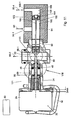
- FIGS. 10 and 11 show a further embodiment of a throttle device 121 according to the invention, to which with respect to the Other figures described first throttle valve 22, a second throttle valve 122 is provided which are mechanically connected to each other such that upon movement of the one throttle valve 22 in the opening direction at the other throttle valve 122 takes place in the closing direction and vice versa during a movement of the throttle valve 22 in Closing direction in the other throttle valve 122 takes place a movement in the opening direction.
- the valve needle 160 of the second throttle valve 122 is formed by an axial extension of the first valve needle 60.
- the second valve 122 has a but in opposite spatial arrangement, a valve head 158, a valve seat 154 and passing therethrough a throttle channel 156th
- the first valve chamber 88 of the first throttle valve 22 has an external compressed air port 88-1.
- the second valve chamber 90 of the first throttle valve 22 is connected via a valve connecting passage 94 to a second valve chamber 190 of the second throttle valve 122.
- the throttle passage 156 of the second throttle valve 122 is located between this second valve chamber 190 and a first valve chamber 188 which is provided with an external compressed air port 188-1.
- the valve connecting passage 94 is provided with an external compressed air port 94-1.
- compressed air source 96 may be pressurized by only the first throttle valve 22 or by both throttle valves 22 and 122 depending on the adjustment of the throttle valves 22 and 122 by the single motor 24 or flow only through the second throttle valve 122, each in a defined quantity distribution, as in the Figures 10 and Figure 22 is schematically illustrated by arrows 96-1, 96-2, 96-3 and 96-4.
- throttle devices according to the invention are powder spray coating devices, since in the powder spray coating, the efficiency and the coating quality is particularly dependent on the precise adjustment of compressed air streams.
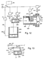
- Fig. 12 1 schematically shows an embodiment of a plurality of possible embodiments of a powder spray coating device according to the invention.
- An injector 200 draws coating powder 202 from a powder container 204 and conveys this powder in a stream of compressed air to a spray device 206, such as a spray gun, which has a spray orifice 208 or a rotary atomizer, not shown.
- a spray device 206 such as a spray gun, which has a spray orifice 208 or a rotary atomizer, not shown.
- a throttle device 21 which is designed according to the invention in the manner described, be arranged in at least one of the following air paths, which are supplied from a pressure source 210 with compressed air 211:
- a conveying air path 212 for conveying compressed air 213 to the Injector 200 for generating a negative pressure in a negative pressure region 214 and thereby for sucking coating powder 202 from the powder container 204; and / or in a soirluftweg 216 for the supply of additional compressed air 217 to the powder-air conveying path 218, in which the coating powder is pneumatically conveyed by the conveying compressed air 213 to the spraying device 206; and / or in a shaping air path 220 for shaping compressed air 221 for forming a sprayed powder cloud 222; and / or in an electrode purge air path 226 for purge compressed air 227 to a high voltage electrode 230 provided for electrostatically charging the coating powder in the powder flow path; and / or in a fluidizing air supply path 232 for fluidizing
- Fig. 13 shows a part of the powder spray coating device of FIG. 12
- the conveying air path 212 and in the additional air path 216 not individual throttling devices 21 according to FIGS FIGS. 2 to 9 are arranged, but for both air paths 212 and 216 together a single throttle device 121 according to the Figures 10 and 11 is arranged.
- the latter is in FIG. 13 shown only schematically.
- the one throttle valve 22 of this throttle device 121 is arranged in the conveying air path 212 for conveying compressed air 213 of the injector 200.
- the other throttle valve 122 of the throttle device 121 is arranged in the additional air path 216 for the supply of additional compressed air 217 in the powder compressed air flow path 218.
- the throttle device 121 is preferably designed such that in an adjustment of the conveying air-compressed air 213 to the same extent (or in another predetermined ratio) and the additional compressed air 217 is adjusted. Thereby, the amount of powder delivered per unit time can be changed by adjusting the delivery air 213, and at the same time the total amount of air in the powder compressed air flow path 218 downstream of the injector 200 can be kept constant.
- a reference position of the throttle valve is defined by means of one or more electrical contact elements.
- valve head of the valve needle is preferably conical in all embodiments of throttle valves, so that in an initial opening portion of the throttle channel upon movement of the valve needle only a small change in the amount of compressed air flowing through is generated and also when opening the throttle valve from the fully closed valve position to a slightly open valve position only a minimal increase in air takes place.
- the throttle valve is fully or nearly fully closed at the reference position.
- the threads 70, 72 of the threaded bushings 62 and 74 are preferably trapezoidal threads.
- the parts which are adjacent to the electrically conductive contact elements are made of electrically non-conductive material.
Landscapes
- Nozzles (AREA)
- Electrostatic Spraying Apparatus (AREA)
- Electrically Driven Valve-Operating Means (AREA)
- Lift Valve (AREA)
- Coating By Spraying Or Casting (AREA)
Applications Claiming Priority (2)
| Application Number | Priority Date | Filing Date | Title |
|---|---|---|---|
| DE102005007242A DE102005007242A1 (de) | 2005-02-17 | 2005-02-17 | Druckluft-Drosselvorrichtung und Pulversprühbeschichtungsvorrichtung |
| PCT/IB2006/000314 WO2006087625A1 (de) | 2005-02-17 | 2006-02-16 | Druckluft-drosselvorrichtung und pulversprühbeschichtungsvorrichtungsvorrichtung |
Publications (2)
| Publication Number | Publication Date |
|---|---|
| EP1858648A1 EP1858648A1 (de) | 2007-11-28 |
| EP1858648B1 true EP1858648B1 (de) | 2010-12-15 |
Family
ID=36283707
Family Applications (1)
| Application Number | Title | Priority Date | Filing Date |
|---|---|---|---|
| EP20060710394 Expired - Lifetime EP1858648B1 (de) | 2005-02-17 | 2006-02-16 | Druckluft-drosselvorrichtung und pulversprühbeschichtungsvorrichtung |
Country Status (14)
| Country | Link |
|---|---|
| US (1) | US8430346B2 (https=) |
| EP (1) | EP1858648B1 (https=) |
| JP (2) | JP2008537064A (https=) |
| KR (1) | KR101289375B1 (https=) |
| CN (1) | CN101115568B (https=) |
| AT (1) | ATE491523T1 (https=) |
| AU (1) | AU2006215376B2 (https=) |
| BR (1) | BRPI0608207A8 (https=) |
| CA (1) | CA2598358C (https=) |
| DE (2) | DE102005007242A1 (https=) |
| ES (1) | ES2357672T3 (https=) |
| MX (1) | MX2007009970A (https=) |
| TW (1) | TWI322243B (https=) |
| WO (1) | WO2006087625A1 (https=) |
Families Citing this family (11)
| Publication number | Priority date | Publication date | Assignee | Title |
|---|---|---|---|---|
| JP5557437B2 (ja) * | 2008-10-01 | 2014-07-23 | 旭サナック株式会社 | 粉体供給装置及び粉体塗装装置 |
| JP2013528061A (ja) | 2010-06-07 | 2013-07-08 | エソテリックス ジェネティック ラボラトリーズ, エルエルシー | 核酸の数え上げ |
| CN101992158B (zh) * | 2010-12-08 | 2012-03-21 | 中冶京诚工程技术有限公司 | 一种用于静电喷涂的流化式喷射器 |
| DE112013001963B4 (de) | 2012-04-09 | 2025-12-24 | Lincoln Industrial Corporation | Schmiermittelentlüftungsventil mit Schrittmotor-Antrieb |
| KR101593373B1 (ko) | 2015-07-21 | 2016-02-17 | (주)수호도장기산업 | 압축공기 정밀제어밸브 |
| US10518284B2 (en) * | 2015-08-04 | 2019-12-31 | Intelligent Agricultural Solutions Llc | Interactive liquid spraying system and method |
| KR101670926B1 (ko) | 2015-12-23 | 2016-11-11 | (주)수호도장기산업 | 압축공기 정밀제어밸브 |
| TWI634264B (zh) | 2017-01-13 | 2018-09-01 | 研能科技股份有限公司 | 空氣馬達 |
| US10801836B2 (en) * | 2017-06-13 | 2020-10-13 | The Boeing Company | Composite parts that facilitate ultrasonic imaging of layer boundaries |
| DE112018005971T5 (de) * | 2017-11-22 | 2020-07-30 | Bete Fog Nozzle Inc. | Sprühdüse |
| KR102136587B1 (ko) * | 2019-09-30 | 2020-07-23 | 이길호 | 경화 방지용 디스펜서 노즐 |
Family Cites Families (30)
| Publication number | Priority date | Publication date | Assignee | Title |
|---|---|---|---|---|
| US1644171A (en) * | 1923-10-11 | 1927-10-04 | Hendrix K Caldwell | Remote gas-control-valve apparatus |
| US1684603A (en) * | 1927-06-03 | 1928-09-18 | Henry L Stephenson | Valve |
| US3335756A (en) * | 1964-09-17 | 1967-08-15 | Peters & Russell Inc | Automatic sequence valve |
| US3620185A (en) * | 1969-09-08 | 1971-11-16 | Itt | Hydraulic control system |
| US4010717A (en) * | 1975-02-03 | 1977-03-08 | The Bendix Corporation | Fuel control system having an auxiliary circuit for correcting the signals generated by the pressure sensor during transient operating conditions |
| DE7606375U1 (de) * | 1976-03-03 | 1976-12-02 | Buerkert Gmbh, 7118 Ingelfingen | Elektrische stellungsanzeige |
| US4200207A (en) * | 1978-02-01 | 1980-04-29 | Nordson Corporation | Hot melt adhesive foam pump system |
| US4406303A (en) * | 1981-08-04 | 1983-09-27 | Acf Industries, Incorporated | Gate valve with position indicator |
| JPS58108667U (ja) * | 1982-01-19 | 1983-07-23 | 太平洋工業株式会社 | 比例制御弁 |
| JPS59128977U (ja) * | 1983-02-07 | 1984-08-30 | 株式会社東芝 | 電動膨張弁 |
| JPS59181379U (ja) * | 1983-05-21 | 1984-12-04 | パロマ工業株式会社 | 給湯器の自動弁装置 |
| JPS6144068U (ja) * | 1984-08-27 | 1986-03-24 | 株式会社 コスモ計器 | 絞り装置 |
| DE3721875A1 (de) * | 1987-07-02 | 1989-01-12 | Gema Ransburg Ag | Verfahren und einrichtung fuer eine pulverspruehbeschichtungsanlage |
| US5080133A (en) * | 1991-04-10 | 1992-01-14 | Allied-Signal Inc. | Control valve assembly |
| US5364066A (en) * | 1993-07-15 | 1994-11-15 | Sporlan Valve Company | Dual port valve with stepper motor actuator |
| ES2173973T3 (es) * | 1994-10-28 | 2002-11-01 | Technolog Ltd | Valvulas. |
| IT1267194B1 (it) * | 1994-12-07 | 1997-01-28 | Dromont S R L | Dispositivo miscelatore di fluidi, in particolare vernici o inchiostri industriali |
| US5765762A (en) * | 1995-01-30 | 1998-06-16 | Abb Industry K.K. | Spray gun type electrostatic paint coating machine |
| US5647543A (en) * | 1995-01-31 | 1997-07-15 | Graco Inc | Electrostatic ionizing system |
| DE19748821A1 (de) * | 1997-11-05 | 1999-05-06 | Itw Gema Ag | Pulver-Sprühbeschichtungsvorrichtung |
| DE19838276A1 (de) * | 1998-08-22 | 2000-02-24 | Itw Gema Ag | Pulver-Sprühbeschichtungsvorrichtung |
| DE19838279A1 (de) * | 1998-08-22 | 2000-02-24 | Itw Gema Ag | Pulver-Sprühbeschichtungsvorrichtung |
| US6460787B1 (en) * | 1998-10-22 | 2002-10-08 | Nordson Corporation | Modular fluid spray gun |
| JP2000213660A (ja) * | 1999-01-22 | 2000-08-02 | Samsung Electronics Co Ltd | 冷凍サイクル用電子膨張弁 |
| DE19910748A1 (de) * | 1999-03-11 | 2000-09-14 | Itw Gema Ag | Pulverbeschichtungsvorrichtung |
| JP3937029B2 (ja) * | 1999-03-26 | 2007-06-27 | 株式会社鷺宮製作所 | 電動弁 |
| JP2002022047A (ja) * | 2000-07-11 | 2002-01-23 | Smc Corp | ネジ式電動絞り弁 |
| DE10044294A1 (de) * | 2000-09-07 | 2002-05-16 | Siemens Ag | Drosselklappenstutzen |
| GB0122208D0 (en) * | 2001-09-14 | 2001-11-07 | Vincent Ltd G | Spray gun |
| CN1300241C (zh) * | 2004-10-15 | 2007-02-14 | 中国科学院理化技术研究所 | 抗菌高吸水性聚合物复合材料及其制备方法 |
-
2005
- 2005-02-17 DE DE102005007242A patent/DE102005007242A1/de not_active Ceased
-
2006
- 2006-02-10 TW TW95104630A patent/TWI322243B/zh not_active IP Right Cessation
- 2006-02-16 BR BRPI0608207A patent/BRPI0608207A8/pt active Search and Examination
- 2006-02-16 EP EP20060710394 patent/EP1858648B1/de not_active Expired - Lifetime
- 2006-02-16 JP JP2007555722A patent/JP2008537064A/ja not_active Withdrawn
- 2006-02-16 CN CN2006800045152A patent/CN101115568B/zh not_active Expired - Lifetime
- 2006-02-16 CA CA 2598358 patent/CA2598358C/en not_active Expired - Fee Related
- 2006-02-16 MX MX2007009970A patent/MX2007009970A/es active IP Right Grant
- 2006-02-16 KR KR1020077018770A patent/KR101289375B1/ko not_active Expired - Fee Related
- 2006-02-16 ES ES06710394T patent/ES2357672T3/es not_active Expired - Lifetime
- 2006-02-16 AU AU2006215376A patent/AU2006215376B2/en not_active Ceased
- 2006-02-16 US US11/816,591 patent/US8430346B2/en active Active
- 2006-02-16 AT AT06710394T patent/ATE491523T1/de active
- 2006-02-16 DE DE200650008508 patent/DE502006008508D1/de not_active Expired - Lifetime
- 2006-02-16 WO PCT/IB2006/000314 patent/WO2006087625A1/de not_active Ceased
-
2012
- 2012-08-24 JP JP2012185900A patent/JP5643267B2/ja not_active Expired - Fee Related
Also Published As
| Publication number | Publication date |
|---|---|
| DE502006008508D1 (de) | 2011-01-27 |
| ATE491523T1 (de) | 2011-01-15 |
| TWI322243B (en) | 2010-03-21 |
| WO2006087625A1 (de) | 2006-08-24 |
| CA2598358C (en) | 2012-05-01 |
| JP2013039563A (ja) | 2013-02-28 |
| WO2006087625A8 (de) | 2007-09-20 |
| CN101115568A (zh) | 2008-01-30 |
| US20090121051A1 (en) | 2009-05-14 |
| KR20070104911A (ko) | 2007-10-29 |
| KR101289375B1 (ko) | 2013-07-29 |
| JP2008537064A (ja) | 2008-09-11 |
| AU2006215376A1 (en) | 2006-08-24 |
| AU2006215376B2 (en) | 2009-09-10 |
| EP1858648A1 (de) | 2007-11-28 |
| CN101115568B (zh) | 2012-02-29 |
| DE102005007242A1 (de) | 2006-08-24 |
| JP5643267B2 (ja) | 2014-12-17 |
| CA2598358A1 (en) | 2006-08-24 |
| US8430346B2 (en) | 2013-04-30 |
| BRPI0608207A8 (pt) | 2016-06-07 |
| TW200632242A (en) | 2006-09-16 |
| ES2357672T3 (es) | 2011-04-28 |
| BRPI0608207A2 (pt) | 2009-12-01 |
| MX2007009970A (es) | 2007-10-11 |
Similar Documents
| Publication | Publication Date | Title |
|---|---|---|
| EP2451586B1 (de) | Farbspritzpistole | |
| DE69530275T2 (de) | Spritzpistole mit einstellbarem Abgabeventil | |
| EP1858648B1 (de) | Druckluft-drosselvorrichtung und pulversprühbeschichtungsvorrichtung | |
| DE4230535C2 (de) | Zweikomponenten-Spritzpistole | |
| EP1661627A1 (de) | Düsenvorrichtung | |
| DE3500983A1 (de) | Elektrostatische spritzpistole | |
| EP2704850A1 (de) | Farbspritzgerät | |
| WO2023041655A1 (de) | Lackierpistole und verfahren zum betreiben einer lackierpistole | |
| DE202015106132U1 (de) | Farbspritzgerät | |
| DE1546838A1 (de) | Vorrichtung zum wahlweisen Zerstaeuben und Auftragen verschiedener Stoffe | |
| DE102010038583A1 (de) | Düsenanordnung zum Abgeben von flüssigem Material | |
| DE1965509C3 (de) | Elektrostatische Spritzpistole | |
| DE19748821A1 (de) | Pulver-Sprühbeschichtungsvorrichtung | |
| EP0467129A2 (de) | Düse für Spritzgiessmaschinen | |
| DE2815246A1 (de) | Lackspritzpistole | |
| EP0681872A2 (de) | Sprühgerät-Befestigungsvorrichtung | |
| DE102011079982B4 (de) | Sprühkopf für reaktive Kunststoffe | |
| DE3711783A1 (de) | Spritzpistole fuer fluessigkeiten, insbesondere lacke | |
| EP2478967A1 (de) | Ventil für eine Spritzpistole, Spritzpistole und Verfahren | |
| DE10212601A1 (de) | Zerstäuber für eine Beschichtungsanlage | |
| EP4268971B1 (de) | Winkeladapter für eine pulversprühvorrichtung | |
| DE19507365A1 (de) | Vorrichtung zum Versprühen eines Zweistoffgemisches | |
| EP1048359B1 (de) | Sprühbeschichtungspistole | |
| WO2012139540A1 (de) | Luftkappe, anordnung aus haltering und luftkappe und farbleiteinrichtung für eine farbspritzpistole | |
| EP0100854A1 (de) | Verstelldüsenanordnung |
Legal Events
| Date | Code | Title | Description |
|---|---|---|---|
| PUAI | Public reference made under article 153(3) epc to a published international application that has entered the european phase |
Free format text: ORIGINAL CODE: 0009012 |
|
| 17P | Request for examination filed |
Effective date: 20070808 |
|
| AK | Designated contracting states |
Kind code of ref document: A1 Designated state(s): AT BE BG CH CY CZ DE DK EE ES FI FR GB GR HU IE IS IT LI LT LU LV MC NL PL PT RO SE SI SK TR |
|
| DAX | Request for extension of the european patent (deleted) | ||
| RAP1 | Party data changed (applicant data changed or rights of an application transferred) |
Owner name: ITW GEMA GMBH |
|
| GRAP | Despatch of communication of intention to grant a patent |
Free format text: ORIGINAL CODE: EPIDOSNIGR1 |
|
| GRAS | Grant fee paid |
Free format text: ORIGINAL CODE: EPIDOSNIGR3 |
|
| GRAA | (expected) grant |
Free format text: ORIGINAL CODE: 0009210 |
|
| AK | Designated contracting states |
Kind code of ref document: B1 Designated state(s): AT BE BG CH CY CZ DE DK EE ES FI FR GB GR HU IE IS IT LI LT LU LV MC NL PL PT RO SE SI SK TR |
|
| REG | Reference to a national code |
Ref country code: CH Ref legal event code: EP Ref country code: GB Ref legal event code: FG4D Free format text: NOT ENGLISH |
|
| REG | Reference to a national code |
Ref country code: IE Ref legal event code: FG4D |
|
| REF | Corresponds to: |
Ref document number: 502006008508 Country of ref document: DE Date of ref document: 20110127 Kind code of ref document: P |
|
| REG | Reference to a national code |
Ref country code: NL Ref legal event code: T3 |
|
| REG | Reference to a national code |
Ref country code: ES Ref legal event code: FG2A Ref document number: 2357672 Country of ref document: ES Kind code of ref document: T3 Effective date: 20110428 |
|
| PG25 | Lapsed in a contracting state [announced via postgrant information from national office to epo] |
Ref country code: LT Free format text: LAPSE BECAUSE OF FAILURE TO SUBMIT A TRANSLATION OF THE DESCRIPTION OR TO PAY THE FEE WITHIN THE PRESCRIBED TIME-LIMIT Effective date: 20101215 |
|
| LTIE | Lt: invalidation of european patent or patent extension |
Effective date: 20101215 |
|
| PG25 | Lapsed in a contracting state [announced via postgrant information from national office to epo] |
Ref country code: LV Free format text: LAPSE BECAUSE OF FAILURE TO SUBMIT A TRANSLATION OF THE DESCRIPTION OR TO PAY THE FEE WITHIN THE PRESCRIBED TIME-LIMIT Effective date: 20101215 Ref country code: CY Free format text: LAPSE BECAUSE OF FAILURE TO SUBMIT A TRANSLATION OF THE DESCRIPTION OR TO PAY THE FEE WITHIN THE PRESCRIBED TIME-LIMIT Effective date: 20101215 Ref country code: SI Free format text: LAPSE BECAUSE OF FAILURE TO SUBMIT A TRANSLATION OF THE DESCRIPTION OR TO PAY THE FEE WITHIN THE PRESCRIBED TIME-LIMIT Effective date: 20101215 Ref country code: BG Free format text: LAPSE BECAUSE OF FAILURE TO SUBMIT A TRANSLATION OF THE DESCRIPTION OR TO PAY THE FEE WITHIN THE PRESCRIBED TIME-LIMIT Effective date: 20110315 Ref country code: SE Free format text: LAPSE BECAUSE OF FAILURE TO SUBMIT A TRANSLATION OF THE DESCRIPTION OR TO PAY THE FEE WITHIN THE PRESCRIBED TIME-LIMIT Effective date: 20101215 Ref country code: FI Free format text: LAPSE BECAUSE OF FAILURE TO SUBMIT A TRANSLATION OF THE DESCRIPTION OR TO PAY THE FEE WITHIN THE PRESCRIBED TIME-LIMIT Effective date: 20101215 |
|
| REG | Reference to a national code |
Ref country code: IE Ref legal event code: FD4D |
|
| PG25 | Lapsed in a contracting state [announced via postgrant information from national office to epo] |
Ref country code: IS Free format text: LAPSE BECAUSE OF FAILURE TO SUBMIT A TRANSLATION OF THE DESCRIPTION OR TO PAY THE FEE WITHIN THE PRESCRIBED TIME-LIMIT Effective date: 20110415 Ref country code: GR Free format text: LAPSE BECAUSE OF FAILURE TO SUBMIT A TRANSLATION OF THE DESCRIPTION OR TO PAY THE FEE WITHIN THE PRESCRIBED TIME-LIMIT Effective date: 20110316 Ref country code: PT Free format text: LAPSE BECAUSE OF FAILURE TO SUBMIT A TRANSLATION OF THE DESCRIPTION OR TO PAY THE FEE WITHIN THE PRESCRIBED TIME-LIMIT Effective date: 20110415 Ref country code: IE Free format text: LAPSE BECAUSE OF FAILURE TO SUBMIT A TRANSLATION OF THE DESCRIPTION OR TO PAY THE FEE WITHIN THE PRESCRIBED TIME-LIMIT Effective date: 20101215 Ref country code: CZ Free format text: LAPSE BECAUSE OF FAILURE TO SUBMIT A TRANSLATION OF THE DESCRIPTION OR TO PAY THE FEE WITHIN THE PRESCRIBED TIME-LIMIT Effective date: 20101215 Ref country code: EE Free format text: LAPSE BECAUSE OF FAILURE TO SUBMIT A TRANSLATION OF THE DESCRIPTION OR TO PAY THE FEE WITHIN THE PRESCRIBED TIME-LIMIT Effective date: 20101215 |
|
| BERE | Be: lapsed |
Owner name: ITW GEMA GMBH Effective date: 20110228 |
|
| PG25 | Lapsed in a contracting state [announced via postgrant information from national office to epo] |
Ref country code: PL Free format text: LAPSE BECAUSE OF FAILURE TO SUBMIT A TRANSLATION OF THE DESCRIPTION OR TO PAY THE FEE WITHIN THE PRESCRIBED TIME-LIMIT Effective date: 20101215 Ref country code: RO Free format text: LAPSE BECAUSE OF FAILURE TO SUBMIT A TRANSLATION OF THE DESCRIPTION OR TO PAY THE FEE WITHIN THE PRESCRIBED TIME-LIMIT Effective date: 20101215 Ref country code: SK Free format text: LAPSE BECAUSE OF FAILURE TO SUBMIT A TRANSLATION OF THE DESCRIPTION OR TO PAY THE FEE WITHIN THE PRESCRIBED TIME-LIMIT Effective date: 20101215 |
|
| PG25 | Lapsed in a contracting state [announced via postgrant information from national office to epo] |
Ref country code: MC Free format text: LAPSE BECAUSE OF NON-PAYMENT OF DUE FEES Effective date: 20110228 |
|
| PLBE | No opposition filed within time limit |
Free format text: ORIGINAL CODE: 0009261 |
|
| STAA | Information on the status of an ep patent application or granted ep patent |
Free format text: STATUS: NO OPPOSITION FILED WITHIN TIME LIMIT |
|
| PG25 | Lapsed in a contracting state [announced via postgrant information from national office to epo] |
Ref country code: DK Free format text: LAPSE BECAUSE OF FAILURE TO SUBMIT A TRANSLATION OF THE DESCRIPTION OR TO PAY THE FEE WITHIN THE PRESCRIBED TIME-LIMIT Effective date: 20101215 |
|
| 26N | No opposition filed |
Effective date: 20110916 |
|
| PG25 | Lapsed in a contracting state [announced via postgrant information from national office to epo] |
Ref country code: BE Free format text: LAPSE BECAUSE OF NON-PAYMENT OF DUE FEES Effective date: 20110228 |
|
| REG | Reference to a national code |
Ref country code: DE Ref legal event code: R097 Ref document number: 502006008508 Country of ref document: DE Effective date: 20110916 |
|
| REG | Reference to a national code |
Ref country code: DE Ref legal event code: R081 Ref document number: 502006008508 Country of ref document: DE Owner name: GEMA SWITZERLAND GMBH, CH Free format text: FORMER OWNER: ITW GEMA GMBH, ST. GALLEN, CH Effective date: 20121213 |
|
| PG25 | Lapsed in a contracting state [announced via postgrant information from national office to epo] |
Ref country code: LU Free format text: LAPSE BECAUSE OF NON-PAYMENT OF DUE FEES Effective date: 20110216 |
|
| PG25 | Lapsed in a contracting state [announced via postgrant information from national office to epo] |
Ref country code: HU Free format text: LAPSE BECAUSE OF FAILURE TO SUBMIT A TRANSLATION OF THE DESCRIPTION OR TO PAY THE FEE WITHIN THE PRESCRIBED TIME-LIMIT Effective date: 20101215 |
|
| REG | Reference to a national code |
Ref country code: CH Ref legal event code: PFA Owner name: GEMA SWITZERLAND GMBH, CH Free format text: FORMER OWNER: ITW GEMA GMBH, CH |
|
| REG | Reference to a national code |
Ref country code: ES Ref legal event code: PC2A Owner name: GEMA SWITZERLAND GMBH Effective date: 20131223 |
|
| REG | Reference to a national code |
Ref country code: FR Ref legal event code: CD Owner name: GEMA SWITZERLAND GMBH Effective date: 20140106 |
|
| REG | Reference to a national code |
Ref country code: NL Ref legal event code: TD Effective date: 20140127 |
|
| REG | Reference to a national code |
Ref country code: AT Ref legal event code: HC Ref document number: 491523 Country of ref document: AT Kind code of ref document: T Owner name: GEMA SWITZERLAND GMBH, CH Effective date: 20131219 |
|
| PGFP | Annual fee paid to national office [announced via postgrant information from national office to epo] |
Ref country code: NL Payment date: 20140226 Year of fee payment: 9 |
|
| PGFP | Annual fee paid to national office [announced via postgrant information from national office to epo] |
Ref country code: ES Payment date: 20140226 Year of fee payment: 9 Ref country code: AT Payment date: 20140203 Year of fee payment: 9 |
|
| REG | Reference to a national code |
Ref country code: NL Ref legal event code: V1 Effective date: 20150901 |
|
| PG25 | Lapsed in a contracting state [announced via postgrant information from national office to epo] |
Ref country code: NL Free format text: LAPSE BECAUSE OF NON-PAYMENT OF DUE FEES Effective date: 20150901 |
|
| REG | Reference to a national code |
Ref country code: AT Ref legal event code: MM01 Ref document number: 491523 Country of ref document: AT Kind code of ref document: T Effective date: 20150216 |
|
| PG25 | Lapsed in a contracting state [announced via postgrant information from national office to epo] |
Ref country code: AT Free format text: LAPSE BECAUSE OF NON-PAYMENT OF DUE FEES Effective date: 20150216 |
|
| REG | Reference to a national code |
Ref country code: FR Ref legal event code: PLFP Year of fee payment: 11 |
|
| REG | Reference to a national code |
Ref country code: ES Ref legal event code: FD2A Effective date: 20160330 |
|
| PG25 | Lapsed in a contracting state [announced via postgrant information from national office to epo] |
Ref country code: ES Free format text: LAPSE BECAUSE OF NON-PAYMENT OF DUE FEES Effective date: 20150217 |
|
| REG | Reference to a national code |
Ref country code: FR Ref legal event code: PLFP Year of fee payment: 12 |
|
| REG | Reference to a national code |
Ref country code: FR Ref legal event code: PLFP Year of fee payment: 13 |
|
| P01 | Opt-out of the competence of the unified patent court (upc) registered |
Effective date: 20230621 |
|
| PGFP | Annual fee paid to national office [announced via postgrant information from national office to epo] |
Ref country code: DE Payment date: 20250227 Year of fee payment: 20 |
|
| PGFP | Annual fee paid to national office [announced via postgrant information from national office to epo] |
Ref country code: CH Payment date: 20250306 Year of fee payment: 20 |
|
| PGFP | Annual fee paid to national office [announced via postgrant information from national office to epo] |
Ref country code: FR Payment date: 20250225 Year of fee payment: 20 |
|
| PGFP | Annual fee paid to national office [announced via postgrant information from national office to epo] |
Ref country code: GB Payment date: 20250227 Year of fee payment: 20 Ref country code: IT Payment date: 20250220 Year of fee payment: 20 |
|
| PGFP | Annual fee paid to national office [announced via postgrant information from national office to epo] |
Ref country code: TR Payment date: 20250205 Year of fee payment: 20 |
|
| REG | Reference to a national code |
Ref country code: CH Ref legal event code: H14 Free format text: ST27 STATUS EVENT CODE: U-0-0-H10-H14 (AS PROVIDED BY THE NATIONAL OFFICE) Effective date: 20260216 Ref country code: DE Ref legal event code: R071 Ref document number: 502006008508 Country of ref document: DE |
|
| REG | Reference to a national code |
Ref country code: GB Ref legal event code: PE20 Expiry date: 20260215 |