EP1858648B1 - Compressed air throttle device and a power spray coatong device - Google Patents
Compressed air throttle device and a power spray coatong device Download PDFInfo
- Publication number
- EP1858648B1 EP1858648B1 EP20060710394 EP06710394A EP1858648B1 EP 1858648 B1 EP1858648 B1 EP 1858648B1 EP 20060710394 EP20060710394 EP 20060710394 EP 06710394 A EP06710394 A EP 06710394A EP 1858648 B1 EP1858648 B1 EP 1858648B1
- Authority
- EP
- European Patent Office
- Prior art keywords
- throttle
- valve
- compressed air
- air
- powder
- Prior art date
- Legal status (The legal status is an assumption and is not a legal conclusion. Google has not performed a legal analysis and makes no representation as to the accuracy of the status listed.)
- Active
Links
- 239000007921 spray Substances 0.000 title description 4
- 239000000843 powder Substances 0.000 claims abstract description 26
- 238000005507 spraying Methods 0.000 claims abstract description 17
- 239000011248 coating agent Substances 0.000 claims description 15
- 238000000576 coating method Methods 0.000 claims description 15
- 229940098458 powder spray Drugs 0.000 claims description 15
- 238000010926 purge Methods 0.000 claims description 4
- 238000007786 electrostatic charging Methods 0.000 claims 1
- 239000011435 rock Substances 0.000 claims 1
- 230000006835 compression Effects 0.000 description 2
- 238000007906 compression Methods 0.000 description 2
- 238000004519 manufacturing process Methods 0.000 description 2
- 230000002093 peripheral effect Effects 0.000 description 2
- 238000007493 shaping process Methods 0.000 description 2
- 230000008878 coupling Effects 0.000 description 1
- 238000010168 coupling process Methods 0.000 description 1
- 238000005859 coupling reaction Methods 0.000 description 1
- 230000001419 dependent effect Effects 0.000 description 1
- 238000009826 distribution Methods 0.000 description 1
- 238000001746 injection moulding Methods 0.000 description 1
- 239000007788 liquid Substances 0.000 description 1
- 239000012811 non-conductive material Substances 0.000 description 1
Images


Classifications
-
- B—PERFORMING OPERATIONS; TRANSPORTING
- B05—SPRAYING OR ATOMISING IN GENERAL; APPLYING FLUENT MATERIALS TO SURFACES, IN GENERAL
- B05B—SPRAYING APPARATUS; ATOMISING APPARATUS; NOZZLES
- B05B7/00—Spraying apparatus for discharge of liquids or other fluent materials from two or more sources, e.g. of liquid and air, of powder and gas
- B05B7/14—Spraying apparatus for discharge of liquids or other fluent materials from two or more sources, e.g. of liquid and air, of powder and gas designed for spraying particulate materials
- B05B7/1404—Arrangements for supplying particulate material
-
- B—PERFORMING OPERATIONS; TRANSPORTING
- B05—SPRAYING OR ATOMISING IN GENERAL; APPLYING FLUENT MATERIALS TO SURFACES, IN GENERAL
- B05B—SPRAYING APPARATUS; ATOMISING APPARATUS; NOZZLES
- B05B12/00—Arrangements for controlling delivery; Arrangements for controlling the spray area
- B05B12/08—Arrangements for controlling delivery; Arrangements for controlling the spray area responsive to condition of liquid or other fluent material to be discharged, of ambient medium or of target ; responsive to condition of spray devices or of supply means, e.g. pipes, pumps or their drive means
- B05B12/085—Arrangements for controlling delivery; Arrangements for controlling the spray area responsive to condition of liquid or other fluent material to be discharged, of ambient medium or of target ; responsive to condition of spray devices or of supply means, e.g. pipes, pumps or their drive means responsive to flow or pressure of liquid or other fluent material to be discharged
-
- B—PERFORMING OPERATIONS; TRANSPORTING
- B05—SPRAYING OR ATOMISING IN GENERAL; APPLYING FLUENT MATERIALS TO SURFACES, IN GENERAL
- B05B—SPRAYING APPARATUS; ATOMISING APPARATUS; NOZZLES
- B05B5/00—Electrostatic spraying apparatus; Spraying apparatus with means for charging the spray electrically; Apparatus for spraying liquids or other fluent materials by other electric means
- B05B5/025—Discharge apparatus, e.g. electrostatic spray guns
- B05B5/053—Arrangements for supplying power, e.g. charging power
- B05B5/0533—Electrodes specially adapted therefor; Arrangements of electrodes
-
- B—PERFORMING OPERATIONS; TRANSPORTING
- B05—SPRAYING OR ATOMISING IN GENERAL; APPLYING FLUENT MATERIALS TO SURFACES, IN GENERAL
- B05B—SPRAYING APPARATUS; ATOMISING APPARATUS; NOZZLES
- B05B5/00—Electrostatic spraying apparatus; Spraying apparatus with means for charging the spray electrically; Apparatus for spraying liquids or other fluent materials by other electric means
- B05B5/16—Arrangements for supplying liquids or other fluent material
-
- B—PERFORMING OPERATIONS; TRANSPORTING
- B05—SPRAYING OR ATOMISING IN GENERAL; APPLYING FLUENT MATERIALS TO SURFACES, IN GENERAL
- B05B—SPRAYING APPARATUS; ATOMISING APPARATUS; NOZZLES
- B05B7/00—Spraying apparatus for discharge of liquids or other fluent materials from two or more sources, e.g. of liquid and air, of powder and gas
- B05B7/14—Spraying apparatus for discharge of liquids or other fluent materials from two or more sources, e.g. of liquid and air, of powder and gas designed for spraying particulate materials
- B05B7/1404—Arrangements for supplying particulate material
- B05B7/1472—Powder extracted from a powder container in a direction substantially opposite to gravity by a suction device dipped into the powder
-
- Y—GENERAL TAGGING OF NEW TECHNOLOGICAL DEVELOPMENTS; GENERAL TAGGING OF CROSS-SECTIONAL TECHNOLOGIES SPANNING OVER SEVERAL SECTIONS OF THE IPC; TECHNICAL SUBJECTS COVERED BY FORMER USPC CROSS-REFERENCE ART COLLECTIONS [XRACs] AND DIGESTS
- Y10—TECHNICAL SUBJECTS COVERED BY FORMER USPC
- Y10T—TECHNICAL SUBJECTS COVERED BY FORMER US CLASSIFICATION
- Y10T137/00—Fluid handling
- Y10T137/8158—With indicator, register, recorder, alarm or inspection means
- Y10T137/8225—Position or extent of motion indicator
- Y10T137/8242—Electrical
-
- Y—GENERAL TAGGING OF NEW TECHNOLOGICAL DEVELOPMENTS; GENERAL TAGGING OF CROSS-SECTIONAL TECHNOLOGIES SPANNING OVER SEVERAL SECTIONS OF THE IPC; TECHNICAL SUBJECTS COVERED BY FORMER USPC CROSS-REFERENCE ART COLLECTIONS [XRACs] AND DIGESTS
- Y10—TECHNICAL SUBJECTS COVERED BY FORMER USPC
- Y10T—TECHNICAL SUBJECTS COVERED BY FORMER US CLASSIFICATION
- Y10T137/00—Fluid handling
- Y10T137/8158—With indicator, register, recorder, alarm or inspection means
- Y10T137/8225—Position or extent of motion indicator
- Y10T137/8275—Indicator element rigidly carried by the movable element whose position is indicated
-
- Y—GENERAL TAGGING OF NEW TECHNOLOGICAL DEVELOPMENTS; GENERAL TAGGING OF CROSS-SECTIONAL TECHNOLOGIES SPANNING OVER SEVERAL SECTIONS OF THE IPC; TECHNICAL SUBJECTS COVERED BY FORMER USPC CROSS-REFERENCE ART COLLECTIONS [XRACs] AND DIGESTS
- Y10—TECHNICAL SUBJECTS COVERED BY FORMER USPC
- Y10T—TECHNICAL SUBJECTS COVERED BY FORMER US CLASSIFICATION
- Y10T137/00—Fluid handling
- Y10T137/8593—Systems
- Y10T137/86493—Multi-way valve unit
- Y10T137/86509—Sequentially progressive opening or closing of plural ports
- Y10T137/86517—With subsequent closing of first port
Definitions
- the invention relates to a compressed air throttle apparatus, in particular for powder spray coating apparatus, according to the preamble of claim 1. Furthermore, the invention relates to a powder spray coating apparatus which includes at least one such throttle device.
- a powder spray coating apparatus with a throttle device of this kind is known from US 5,156,237 EP 1 156 882 B1 known. It contains an electric stepper motor which rotates a valve member via a bellows coupling.
- the valve member has a thread which engages a housing thread, so that the valve member is also axially displaced during its rotation relative to a valve seat to adjust the opening width of a throttle valve provided in the valve seat.
- the patent also shows a throttle device with two throttle valves, which are arranged opposite to each other and are driven by the same stepper motor, so that at an opening movement at one throttle valve, the other throttle valve performs a closing movement, or vice versa, depending on the direction of rotation of the stepping motor.
- the stepping motor is rotated from a reference position by a certain number of steps.
- the throttle valve in the reference position the smallest opening cross-section, which latter may either be completely closed or may be slightly open for a compressed air leakage current, which is measured before the start of the throttle device and the electrical control of the stepping motor is taken into account for setting a desired operating compressed air flow.
- FIG. 1 The drawings attached hereto show a known from practice embodiment of a powder spray coating apparatus according to said EP 1 156 882 B1 ,
- An electric stepping motor 2 is driven by an electric control device, not shown, to rotate about a bellows 4 a valve member 6 by a predetermined number of rotation steps, thereby adjusting a valve needle head 8 of the valve member 6 relative to a valve seat 10 and thereby the opening width of a set in the valve seat 10 formed throttle channel 12.
- the valve member 6 is provided with a thread 14 which engages in a thread 16 of a housing 17, so that the rotational movement of the stepping motor 2 is converted into an axial movement of the valve member 6.
- the throttle channel 12 can be opened by more than a single turn of 360 ° of the valve member 6, the two stops 18 and 20 already shortly before a complete revolution of 360 ° again as far axially distance accordingly FIG. 1 have from each other that they can be moved past each other in the direction of rotation are.
- the problem to be solved is to provide a possibility by which fine adjustments of the throttle device are possible in a simpler manner than in the prior art.
- the invention is useful not only for powder coating apparatus, but also for all other applications where fine adjustments of compressed air streams or liquid streams are required.
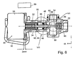
- the compressed air throttle device 21 which in the FIGS. 2 to 9 includes a throttle valve 22 and a controllable electric motor 24 with a motor shaft 26 for adjusting the throttle valve 22.
- the motor 24 may be any type of engine, the motor shaft 26 is controlled to defined rotational angle positions adjustable. It is preferably an electric stepper motor.
- the motor housing 30 of the electric motor 24 is held by a spring clip 32 to a valve housing 34.
- the spring clip 32 is between a rear end face 36 of the motor housing 30 and a front end face 37 of a Flange 38 of the valve housing 34 axially tensioned. To prevent rotation of the motor housing 30 to the valve housing 34, these two parts are connected to an eccentric to the axial center line 39 of the motor 24 axially parallel connector.
- the latter can, for example, have a projection 40, for example on the valve housing 34, and a recess 42 receiving this projection 40 on the respective other part, for example the motor housing 30, as it does FIG. 2 schematically shows.
- the rotation lock could also be achieved by other means, for example by a screw between the motor housing 30 and the flange 38th
- an electrical current path 44 which has at least two, for example three electrically conductive contact elements 46, 48, 50 for alternatively interrupting and closing the current path 44 as a function of the setting of the throttle valve 22.
- At least one of the contact elements for example the contact element 50, provided on an axially adjustable valve member 52 and together with this contact element 50 relative to the at least one other of the contact elements, for example relative to the other two contact elements 46 and 48 and while at the same time relative to a valve seat 54 of the throttle valve 22 of the motor 24 movable to change the opening width of a throttle valve 56 formed in the valve seat 54 by means of a valve head 58 of a valve element, preferably a valve needle 60, which is part of the adjustable valve member 52.
- the valve needle 60 is connected to the motor shaft 26 such that it is axially adjustable by rotations of the motor shaft 26 without the valve needle 60 rotates.
- the valve needle 60 is guided axially in a passage opening 64 of the valve housing 34.
- the passage opening 64 has a non-circular shape, preferably a polygonal shape, for example a quadrangular shape, at least over part of its length, to prevent rotation of the valve pin 60.
- a threaded bush 62 is fixed to the rear end of the valve needle 60, preferably in the Injection molding process molded, which has a polygonal outer peripheral portion 66 which is guided axially on a polygonal inner peripheral portion 68 of the through hole 64.
- the threaded bushing 62 has an internal thread 70 which engages in an external thread 72 of a second threaded bushing 74, which is arranged in a rotationally fixed manner on the motor shaft 26.
- the electrically conductive contact elements 46, 48 and 50 of the electrical current path 44 are arranged in the passage opening 64 between a forwardly facing end face 76 and a rearwardly facing end face 78 of an intermediate element 80 around the valve needle 60 around.
- the intermediate element 80 abuts axially on a rearwardly facing end face 82 of a shoulder of the passage opening 64.
- An opening portion 84 of the passage opening 64 which is narrowed by the shoulder 82 is sealed by a seal 86 with respect to a first valve chamber 88.
- the throttle valve 22 is located between the first valve chamber 88 and a second valve chamber 90.
- the two fixedly arranged contact elements 44 and 46 are immovably mounted on the rearwardly facing end face 78 of the intermediate element 80 spaced apart in a transverse plane which extends at right angles to the center line 39.
- the movable contact element 50 is movably arranged together with the movable valve part 52 and designed as a contact bridge for bridging the two a contact elements 44, 46, so that the electrical contact elements form a button. Trained as a contact bridge contact element 50 contacts and bridges the two stationary contact elements 44 and 46 respectively only when the valve needle 60 is in a predetermined reference position, preferably when the valve needle 60, the throttle channel 56 almost completely or preferably completely closes, as it Figures 2 . 3 and 4 demonstrate.
- a reference signal is generated in an electrical control device 89 shown only schematically, which corresponds to a reference setting (reference position) of the throttle valve 22, which is preferably the fully or almost completely closed closed position of the throttle valve. If the reference position is only a partially closed position of the throttle valve 22, the resulting leakage current can be measured at compressed air, which flows through the throttle valve 22.
- the throttle valve 22 is opened a little wider and thus allowed a little more compressed air through the throttle valve 22 therethrough.
- each of the electric control device 89 required by the motor 24 rotation step corresponds to a predetermined, measurable amount of compressed air, which flows through the throttle valve 22. A desired compressed air flow rate can thus be reproduced at any time.
- the throttle device is designed such that at the beginning of a movement of the valve needle 60 in the opening direction and the movable with the valve needle 60 contact element 50 away from the stationary contact elements 46 and 48 and thereby the current path 44 is opened.
- the adjustable valve member 52 and thus the valve needle 60 for example, be adjusted by an adjustment of 6 millimeters, wherein the axial distance of the rear end of the threaded bushing 62 of the motor housing 30 in the reference position according to FIGS. 2 to 4 For example, 8 millimeters and in the fully open valve position according to the FIGS. 6 to 8 for example, 2 millimeters.
- the electrically conductive contact elements 46, 48, 50 are only in the reference position of the valve needle 60, but in no other possible axial settings of the valve needle 60 in contact with each other.
- the electrical current path 44 is closed when contacting the contact elements 46, 48, 50 and interrupted when not contacting.
- valve needle 60 For carrying out the invention, another reference position of the valve needle 60 could be selected instead of the preferred reference position.
- the two stationary contact elements 44 and 46 each have an electrical connection element 46-1 or 48-1, which in the Figures 5 and 9 can be seen.
- the movable contact element 50 which is connected to the movable valve member 52, preferably the valve needle 60, for common movement, is preferably an electrically conductive contact ring which surrounds the valve needle 60 and rests on a forward facing support surface 92 tiltable, which latter on the Valve needle 60 or preferably according to the drawings on a forward projecting annular collar 94 of the threaded bushing 62 is formed.
- the contact ring 50 Due to the tiltability of the contact ring 50 it is ensured that it also abuts not only one, but both stationary contact elements 46 and 48 and electrically connects them together, if the contact surfaces of these contact elements 46 and 48 are not parallel to the contact ring 50 serving as the contact bridge are arranged.
- a compression spring 96 designed as a helical spring is axially clamped between the movable contact element 50 (contact bridge, contact ring) and the intermediate element 80 in order to hold the contact element 50 against the bearing surface 92 in all axial settings of the adjustable valve part 52.
- the compression spring 96 also causes that the teeth of the threads 70 and 72 always abut each other in the same axial direction, so that the clearance between these threads and tolerances have no influence on the setting accuracy of the throttle valve 22.
- none of the electrically conductive contact elements is a bridge element, but it is only one of the two fixed contact elements 46 or 48 is provided and the movable contact element 50 is provided with an electrical connection element which is connected to the electrical control device 89 is such that in the latter a signal is generated when the two contact elements 50 and 46 (or according to other embodiments 50 and 48) contact each other in the in FIG. 2 shown reference position, or not contact each other in all other positions of the valve needle 60th
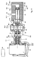
- FIGS. 10 and 11 show a further embodiment of a throttle device 121 according to the invention, to which with respect to the Other figures described first throttle valve 22, a second throttle valve 122 is provided which are mechanically connected to each other such that upon movement of the one throttle valve 22 in the opening direction at the other throttle valve 122 takes place in the closing direction and vice versa during a movement of the throttle valve 22 in Closing direction in the other throttle valve 122 takes place a movement in the opening direction.
- the valve needle 160 of the second throttle valve 122 is formed by an axial extension of the first valve needle 60.
- the second valve 122 has a but in opposite spatial arrangement, a valve head 158, a valve seat 154 and passing therethrough a throttle channel 156th
- the first valve chamber 88 of the first throttle valve 22 has an external compressed air port 88-1.
- the second valve chamber 90 of the first throttle valve 22 is connected via a valve connecting passage 94 to a second valve chamber 190 of the second throttle valve 122.
- the throttle passage 156 of the second throttle valve 122 is located between this second valve chamber 190 and a first valve chamber 188 which is provided with an external compressed air port 188-1.
- the valve connecting passage 94 is provided with an external compressed air port 94-1.
- compressed air source 96 may be pressurized by only the first throttle valve 22 or by both throttle valves 22 and 122 depending on the adjustment of the throttle valves 22 and 122 by the single motor 24 or flow only through the second throttle valve 122, each in a defined quantity distribution, as in the Figures 10 and Figure 22 is schematically illustrated by arrows 96-1, 96-2, 96-3 and 96-4.
- throttle devices according to the invention are powder spray coating devices, since in the powder spray coating, the efficiency and the coating quality is particularly dependent on the precise adjustment of compressed air streams.
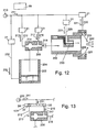
- Fig. 12 1 schematically shows an embodiment of a plurality of possible embodiments of a powder spray coating device according to the invention.
- An injector 200 draws coating powder 202 from a powder container 204 and conveys this powder in a stream of compressed air to a spray device 206, such as a spray gun, which has a spray orifice 208 or a rotary atomizer, not shown.
- a spray device 206 such as a spray gun, which has a spray orifice 208 or a rotary atomizer, not shown.
- a throttle device 21 which is designed according to the invention in the manner described, be arranged in at least one of the following air paths, which are supplied from a pressure source 210 with compressed air 211:
- a conveying air path 212 for conveying compressed air 213 to the Injector 200 for generating a negative pressure in a negative pressure region 214 and thereby for sucking coating powder 202 from the powder container 204; and / or in a soirluftweg 216 for the supply of additional compressed air 217 to the powder-air conveying path 218, in which the coating powder is pneumatically conveyed by the conveying compressed air 213 to the spraying device 206; and / or in a shaping air path 220 for shaping compressed air 221 for forming a sprayed powder cloud 222; and / or in an electrode purge air path 226 for purge compressed air 227 to a high voltage electrode 230 provided for electrostatically charging the coating powder in the powder flow path; and / or in a fluidizing air supply path 232 for fluidizing
- Fig. 13 shows a part of the powder spray coating device of FIG. 12
- the conveying air path 212 and in the additional air path 216 not individual throttling devices 21 according to FIGS FIGS. 2 to 9 are arranged, but for both air paths 212 and 216 together a single throttle device 121 according to the Figures 10 and 11 is arranged.
- the latter is in FIG. 13 shown only schematically.
- the one throttle valve 22 of this throttle device 121 is arranged in the conveying air path 212 for conveying compressed air 213 of the injector 200.
- the other throttle valve 122 of the throttle device 121 is arranged in the additional air path 216 for the supply of additional compressed air 217 in the powder compressed air flow path 218.
- the throttle device 121 is preferably designed such that in an adjustment of the conveying air-compressed air 213 to the same extent (or in another predetermined ratio) and the additional compressed air 217 is adjusted. Thereby, the amount of powder delivered per unit time can be changed by adjusting the delivery air 213, and at the same time the total amount of air in the powder compressed air flow path 218 downstream of the injector 200 can be kept constant.
- a reference position of the throttle valve is defined by means of one or more electrical contact elements.
- valve head of the valve needle is preferably conical in all embodiments of throttle valves, so that in an initial opening portion of the throttle channel upon movement of the valve needle only a small change in the amount of compressed air flowing through is generated and also when opening the throttle valve from the fully closed valve position to a slightly open valve position only a minimal increase in air takes place.
- the throttle valve is fully or nearly fully closed at the reference position.
- the threads 70, 72 of the threaded bushings 62 and 74 are preferably trapezoidal threads.
- the parts which are adjacent to the electrically conductive contact elements are made of electrically non-conductive material.
Landscapes
- Nozzles (AREA)
- Electrostatic Spraying Apparatus (AREA)
- Electrically Driven Valve-Operating Means (AREA)
- Coating By Spraying Or Casting (AREA)
- Lift Valve (AREA)
Abstract
Description
Die Erfindung betrifft eine Druckluft-Drosselvorrichtung, insbesondere für Pulversprühbeschichtungsvorrichtungen, gemäß dem Oberbegriff von Anspruch 1. Ferner betrifft die Erfindung eine Pulversprühbeschichtungsvorrichtung, welche mindestens eine solche Drosselvorrichtung enthält.The invention relates to a compressed air throttle apparatus, in particular for powder spray coating apparatus, according to the preamble of
Eine Pulversprühbeschichtungsvorrichtung mit einer Drosselvorrichtung dieser Art ist aus der
In der praktischen Anwendung der bekannten Drosselvorrichtung hat das Drosselventil in der Referenzposition den kleinsten Öffnungsquerschnitt, welch letzterer entweder vollständig geschlossen sein kann oder leicht geöffnet sein kann für einen Druckluft-Leckstrom, welcher vor der Inbetriebnahme der Drosselvorrichtung gemessen wird und bei der elektrischen Ansteuerung des Schrittmotors zur Einstellung eines gewünschten Betriebs-Druckluftstromes berücksichtigt wird. In der Praxis hat es sich wegen Herstelltoleranzen und wegen der zu berücksichtigenden Winkelstellung der Motorwelle beim Beenden eines Drehbewegungsschrittes als äußerst schwierig erwiesen, die vollständige Schließstellung des Drosselventils als Referenzposition zu verwenden, von welcher aus die Schritte des Schrittmotors gezählt werden, um eine bestimmte Druckluftströmung durch das Drosselventil hindurch zu lassen.In the practical application of the known throttle device, the throttle valve in the reference position, the smallest opening cross-section, which latter may either be completely closed or may be slightly open for a compressed air leakage current, which is measured before the start of the throttle device and the electrical control of the stepping motor is taken into account for setting a desired operating compressed air flow. In practice, it has proved because of manufacturing tolerances and because of the taking into account the angular position of the motor shaft at the completion of a rotary movement step to use the full closed position of the throttle valve as a reference position, from which the steps of the stepping motor are counted to a certain compressed air flow through to let the throttle valve through.
Durch die Erfindung soll die Aufgabe gelöst werden, eine Möglichkeit zu schaffen, durch welche Feineinstellungen der Drosselvorrichtung auf einfachere Weise als beim Stand der Technik möglich sind.By the invention the problem to be solved is to provide a possibility by which fine adjustments of the throttle device are possible in a simpler manner than in the prior art.
Diese Aufgabe wird gemäß der Erfindung durch die Merkmale der Drosselvorrichtung nach Anspruch 1 gelöst.This object is achieved according to the invention by the features of the throttle device according to
Besonders vorteilhaft ist die Anwendung einer solchen Drosselvorrichtung gemäß der Erfindung bei Pulversprühbeschichtungsvorrichtungen, weil es dort zur Erzielung von guten Beschichtungsqualitäten und zur Erzielung eines guten Wirkungsgrads bezüglich der erforderlichen Menge an Beschichtungspulver besonders wichtig ist, die dazu erforderlichen Druckluftströme genau und damit in feinen kleinen Schritten oder schrittlos und damit kontinuierlich einstellen zu können. Alle diese Möglichkeiten bietet die neue Erfindung.Particularly advantageous is the use of such a throttle device according to the invention in Pulversprühbeschichtungsvorrichtungen, because it is there to achieve good coating qualities and to achieve a good efficiency with respect to the required amount of coating powder is particularly important, the required compressed air flows exactly and thus in fine small steps or to be able to adjust continuously and thus continuously. All these possibilities are offered by the new invention.
Die Erfindung ist jedoch nicht nur für Pulverbeschichtungsvorrichtungen verwendbar, sondern auch für alle anderen Anwendungen, wo Feineinstellungen von Druckluftströmen oder von Flüssigkeitsströmen erforderlich sind.However, the invention is useful not only for powder coating apparatus, but also for all other applications where fine adjustments of compressed air streams or liquid streams are required.
Weitere Merkmale sind in den Unteransprüchen enthalten.Further features are contained in the subclaims.
Die Erfindung wird im folgenden mit Bezug auf die Zeichnungen anhand von bevorzugten Ausführungsformen der Erfindung als Beispiele beschrieben. In den Zeichnungen zeigen
- Fig. 1
- schematisch und teilweise im Axialschnitt eine Druckluft-Drosselvorrichtung nach dem Stand der Technik für eine Pulversprühbeschichtungsvorrichtung,
- Fig. 2
- eine Druckluft-Drosselvorrichtung nach der Erfindung im Axialschnitt längs der Ebene II-II von
Figur 5 gesehen in vollständiger oder teilweiser Schließstellung, was bei dieser Ausführungsform eine Referenzposition für die Steuerung der Drosselvorrichtung ist, - Fig. 3
- ein vergrößertes Detail III von
Figur 2 - Fig. 4
- ein vergrößertes Detail IV von
Figur 2 - Fig. 5
- eine Vorderansicht der Drosselvorrichtung von
Figur 2Figur 2 - Fig. 6
- einen Axialschnitt der Drosselvorrichtung nach der Erfindung in einer vollständigen Offenstellung des Drosselventils,
- Fig. 7
- ein vergrößertes Detail VII von
Figur 6 - Fig. 8
- ein vergrößertes Detail VIII von
Figur 6 - Fig. 9
- eine Rückansicht der Drosselvorrichtung nach der Erfindung in Richtung eines Pfeils IX von
Figur 6 - Fig. 10
- einen Längsschnitt einer weiteren Ausführungsform einer Drosselvorrichtung nach der Erfindung ähnlich der ersten Ausführungsform nach der Erfindung in einer vollständigen oder teilweisen Schließstellung des beschriebenen ersten Drosselventils, wobei diese Schließstellung als Referenzposition für die Steuerung der Drosselvorrichtung dient, und wobei zusätzlich zu dem beschriebenen ersten Drosselventil ein zweites Drosselventil vorgesehen ist, welches in Öffnungsrichtung bewegt wird, wenn das erste Drosselventil in Schließrichtung bewegt wird, und welches in umgekehrter Weise in Schließrichtung bewegt wird, wenn das erste Drosselventil in Öffnungsrichtung bewegt wird, wobei
Figur 10 - Fig. 11
- die Drosselvorrichtung von
Figur 10 - Fig. 12
- schematisch eine Pulversprühbeschichtungsvorrichtung nach der Erfindung, welche mindestens in einem Druckluftweg eine Drosselvorrichtung nach der Erfindung entsprechend einer der
Figuren 2 bis 10 - Fig. 13
- einen Teil der Pulversprühbeschichtungsvorrichtung nach
Figur 12Figuren 2 bis 9Figuren 1011 verwendet wird.
- Fig. 1
- schematically and partially in axial section of a compressed air throttle device according to the prior art for a powder spray coating device,
- Fig. 2
- a compressed air throttle device according to the invention in axial section along the plane II-II of
FIG. 5 seen in full or partial closed position, which in this embodiment is a reference position for the control of the throttle device, - Fig. 3
- an enlarged detail III of
FIG. 2 . - Fig. 4
- an enlarged detail IV of
FIG. 2 . - Fig. 5
- a front view of the throttle device of
FIG. 2 in the direction of an arrow V ofFIG. 2 seen, - Fig. 6
- an axial section of the throttle device according to the invention in a fully open position of the throttle valve,
- Fig. 7
- an enlarged detail VII of
FIG. 6 . - Fig. 8
- an enlarged detail VIII of
FIG. 6 . - Fig. 9
- a rear view of the throttle device according to the invention in the direction of an arrow IX of
FIG. 6 seen, - Fig. 10
- a longitudinal section of another embodiment of a throttle device according to the invention similar to the first embodiment of the invention in a full or partial closed position of the described first throttle valve, this closed position serves as a reference position for the control of the throttle device, and wherein in addition to the described first throttle valve, a second throttle valve is provided, which is moved in the opening direction when the first throttle valve moves in the closing direction is moved, and which is reversely moved in the closing direction when the first throttle valve is moved in the opening direction, wherein
FIG. 10 shows the first throttle valve in the closed position or partial closed position and the second throttle valve in complete or almost complete open position, - Fig. 11
- the throttle device of
FIG. 10 wherein the first throttle valve is fully or nearly fully opened and the second throttle valve is fully or partially closed, - Fig. 12
- schematically a powder spray coating apparatus according to the invention, which at least in a compressed air path, a throttle device according to the invention according to one of
FIGS. 2 to 10 contains - Fig. 13
- a part of the powder spray coating device according to
FIG. 12 , wherein instead of two throttle devices after theFIGS. 2 to 9 a throttle device with two oppositely arranged and jointly operated throttle valves after theFigures 10 and11 is used.
Die Druckluft-Drosselvorrichtung 21 nach der Erfindung, welche in den
Ferner ist gemäß der Erfindung ein elektrischer Strompfad 44 vorgesehen, welcher mindestens zwei, beispielsweise drei elektrisch leitfähige Kontaktelemente 46, 48, 50 zum alternativen Unterbrechen und Schließen des Strompfades 44 in Abhängigkeit von der Einstellung des Drosselventils 22 aufweist.Furthermore, according to the invention, an electrical
Gemäß einer besonderen Ausführungsform der Erfindung ist mindestens eines der Kontaktelemente, beispielsweise das Kontaktelement 50, an einem axial verstellbaren Ventilteil 52 vorgesehen und zusammen mit diesem Kontaktelement 50 relativ zu dem mindestens einen anderen der Kontaktelemente, beispielsweise relativ zu den beiden anderen Kontaktelementen 46 und 48 und dabei gleichzeitig relativ zu einem Ventilsitz 54 des Drosselventils 22 von dem Motor 24 bewegbar zur Veränderung der Öffnungsweite eines im Ventilsitz 54 gebildeten Drosselkanals 56 mittels eines Ventil kopfes 58 eines Ventilelementes, vorzugsweise einer Ventilnadel 60, welche Bestandteil des verstellbaren Ventilteils 52 ist.According to a particular embodiment of the invention, at least one of the contact elements, for example the
Die Ventilnadel 60 ist mit der Motorwelle 26 derart verbunden, dass sie durch Drehungen der Motorwelle 26 axial verstellbar ist, ohne dass sich die Ventilnadel 60 dreht. Hierfür ist die Ventilnadel 60 in einer Durchgangsöffnung 64 des Ventilgehäuses 34 axial geführt. Die Durchgangsöffnung 64 hat mindestens auf einem Teil ihrer Länge eine unrunde Form, vorzugsweise eine mehreckige Form, zum Beispiel eine viereckige Form, um eine Drehung der Ventilnadel 60 zu verhindern. Gemäß der in den Zeichnungen gezeigten bevorzugten Ausführungsform ist an dem hinteren Ende der Ventilnadel 60 eine Gewindebuchse 62 befestigt, vorzugsweise im Spritzgussverfahren angespritzt, welche einen mehrkantigen Außenumfangsabschnitt 66 aufweist, welcher an einem mehrkantigen Innenumfangsabschnitt 68 der Durchgangsöffnung 64 axial geführt ist. Die Gewindebuchse 62 hat ein Innengewinde 70, welches in ein Außengewinde 72 einer auf der Motorwelle 26 drehfest angeordneten zweiten Gewindebuchse 74 eingreift.The
Die elektrisch leitfähigen Kontaktelemente 46, 48 und 50 des elektrischen Strompfades 44 sind in der Durchgangsöffnung 64 zwischen einer nach vorne zeigenden Stirnfläche 76 und einer nach hinten zeigenden Stirnfläche 78 eines Zwischenelementes 80 um die Ventilnadel 60 herum angeordnet. Das Zwischenelement 80 liegt axial an einer nach hinten zeigenden Stirnfläche 82 eines Absatzes der Durchgangsöffnung 64 an.The electrically
Ein durch den Absatz 82 verengter Öffnungsabschnitt 84 der Durchgangsöffnung 64 ist durch eine Dichtung 86 gegenüber einer ersten Ventilkammer 88 abgedichtet. Das Drosselventil 22 befindet sich zwischen der ersten Ventilkammer 88 und einer zweiten Ventilkammer 90.An opening
Bei der bevorzugten Ausführungsform nach der Erfindung sind die beiden ortsfest angeordneten Kontaktelemente 44 und 46 an der nach hinten zeigenden Stirnfläche 78 des Zwischenelements 80 mit Abstand voneinander in einer Querebene unbeweglich angeordnet, welche sich rechtwinklig zur Mittellinie 39 erstreckt. Das bewegliche Kontaktelement 50 ist zusammen mit dem bewegbaren Ventilteil 52 bewegbar angeordnet und als Kontaktbrücke zur Überbrückung der beiden einen Kontaktelemente 44, 46 ausgebildet, sodass die elektrischen Kontaktelemente einen Taster bilden. Das als Kontaktbrücke ausgebildete Kontaktelement 50 berührt und überbrückt die beiden ortsfesten Kontaktelemente 44 und 46 jeweils nur dann, wenn die Ventilnadel 60 in einer vorbestimmten Referenzposition ist, vorzugsweise dann, wenn die Ventilnadel 60 den Drosselkanal 56 nahezu vollständig oder vorzugsweise vollständig verschließt, wie es die
Wenn die elektrischen Kontakte 46, 48, 50 geschlossen sind, wird in einer nur schematisch gezeigten elektrischen Steuereinrichtung 89 ein Referenzsignal erzeugt, welches einer Referenzeinstellung (Referenzposition) des Drosselventils 22 entspricht, welches vorzugsweise die vollständig oder nahezu vollständig geschlossene Schließstellung des Drosselventils ist. Wenn die Referenzposition eine nur teilweise Schließstellung des Drosselventils 22 ist, kann der dadurch entstehende Leckstrom an Druckluft gemessen werden, welcher durch das Drosselventil 22 strömt. Bei jedem Schritt des Schrittmotors 24 wird das Drosselventil 22 etwas weiter geöffnet und damit etwas mehr Druckluft durch das Drosselventil 22 hindurch gelassen. Dadurch entspricht jeder von der elektrischen Steuereinrichtung 89 von dem Motor 24 geforderte Drehschritt einer vorbestimmten, messbaren Druckluftmenge, welche durch das Drosselventil 22 strömt. Eine gewünschte Druckluft-Strömungsmenge ist damit jederzeit reproduzierbar.When the
Die Drosselvorrichtung ist derart ausgebildet, dass sich bei Beginn einer Bewegung der Ventilnadel 60 in Öffnungsrichtung auch das mit der Ventilnadel 60 bewegbare Kontaktelement 50 von den ortsfesten Kontaktelementen 46 und 48 entfernt und dadurch der Strompfad 44 geöffnet wird.The throttle device is designed such that at the beginning of a movement of the
Wie die
Zur Ausführung der Erfindung könnte an Stelle der bevorzugten Referenzposition auch eine andere Referenzposition der Ventilnadel 60 gewählt werden.For carrying out the invention, another reference position of the
Die beiden ortsfesten Kontaktelemente 44 und 46 haben jeweils ein elektrisches Anschlusselement 46-1 bzw. 48-1, welche in den
Eine als Schraubenfeder ausgebildete Druckfeder 96 ist zwischen das bewegbare Kontaktelement 50 (Kontaktbrücke, Kontaktring) und das Zwischenelement 80 axial eingespannt, um das Kontaktelement 50 an der Lagerfläche 92 in Anlage zu halten bei allen Axialeinstellungen des verstellbaren Ventilteils 52. Die Druckfeder 96 bewirkt außerdem, dass die Zähne der Gewinde 70 und 72 immer in gleicher Axialrichtung aneinander anliegen, sodass Spielraum zwischen diesen Gewinden und Toleranzen keinen Einfluss auf die Einstellgenauigkeit des Drosselventils 22 haben.A
Gemäß einer anderen, nicht gezeigten Ausführungsform der Erfindung ist keines der elektrisch leitfähigen Kontaktelemente ein Brückenelement, sondern es ist nur eines der beiden ortsfesten Kontaktelemente 46 oder 48 vorgesehen und das bewegbare Kontaktelement 50 ist mit einem elektrischen Anschlusselement versehen, welches mit der elektrischen Steuereinrichtung 89 verbunden ist, sodass in Letzterer ein Signal erzeugt wird, wenn die beiden Kontaktelemente 50 und 46 (oder gemäß anderer Ausführungsform 50 und 48) einander kontaktieren in der in
Die
Die erste Ventilkammer 88 des ersten Drosselventils 22 hat einen externen Druckluftanschluss 88-1. Die zweite Ventilkammer 90 des ersten Drosselventils 22 ist über einen Ventilverbindungskanal 94 mit einer zweiten Ventilkammer 190 des zweiten Drosselventils 122 verbunden. Der Drosselkanal 156 des zweiten Drosselventils 122 befindet sich zwischen dieser zweiten Ventilkammer 190 und einer ersten Ventilkammer 188, welche mit einem externen Druckluftanschluss 188-1 versehen ist. Der Ventilverbindungskanal 94 ist mit einem externen Druckluftanschluss 94-1 versehen. Wenn der externe Druckluftanschluss 94-1 des Ventilverbindungskanals 94 an eine Druckluftquelle angeschlossen ist, kann Druckluft 96 der Druckluftquelle in Abhängigkeit von der Einstellung der Drosselventile 22 und 122 durch den einzigen Motor 24 entweder nur durch das erste Drosselventil 22 oder durch beide Drosselventile 22 und 122 oder nur durch das zweite Drosselventil 122 strömen, jeweils in einer definierten Mengenverteilung, wie dies in den
Ein bevorzugtes Anwendungsgebiet für Drosselvorrichtungen nach der Erfindung sind Pulversprühbeschichtungsvorrichtungen, da bei der Pulversprühbeschichtung der Wirkungsgrad und die Beschichtungsqualität besonders stark von der genauen Einstellung von Druckluftströmen abhängig ist.A preferred application for throttle devices according to the invention are powder spray coating devices, since in the powder spray coating, the efficiency and the coating quality is particularly dependent on the precise adjustment of compressed air streams.
Dadurch kann die pro Zeiteinheit geförderte Pulvermenge durch Verstellen der Förder-Druckluft 213 verändert werden und gleichzeitig die Gesamtluftmenge im Pulver-Druckluft-Strömungsweg 218 stromabwärts des Injektors 200 konstant gehalten werden. Dies ist eine bevorzugte Ausführungsform, welche jedoch andere Ausführungsformen der Erfindung nicht ausschließt. Bei allen Ausführungsformen der Erfindung besteht ein wesentliches Merkmal darin, dass eine Referenzposition des Drosselventils mittels eines oder mehrerer elektrischer Kontaktelemente definiert wird.
Thereby, the amount of powder delivered per unit time can be changed by adjusting the
Der Ventilkopf der Ventilnadel ist bei allen Ausführungsformen von Drosselventilen vorzugsweise konisch, sodass in einem anfänglichen Öffnungsbereich des Drosselkanals bei einer Bewegung der Ventilnadel nur eine kleine Änderung der durchströmenden Druckluftmenge erzeugt wird und auch beim Öffnen des Drosselventils von der vollständig geschlossenen Ventilstellung in eine geringfügig geöffnete Ventilstellung nur ein minimaler Luftanstieg erfolgt.The valve head of the valve needle is preferably conical in all embodiments of throttle valves, so that in an initial opening portion of the throttle channel upon movement of the valve needle only a small change in the amount of compressed air flowing through is generated and also when opening the throttle valve from the fully closed valve position to a slightly open valve position only a minimal increase in air takes place.
Bei den bevorzugten Ausführungsformen ist das Drosselventil in der Referenzposition vollständig oder nahezu vollständig geschlossen.In the preferred embodiments, the throttle valve is fully or nearly fully closed at the reference position.
Die Gewinde 70, 72 der Gewindebuchsen 62 und 74 sind vorzugsweise Trapezgewinde.The
Die Teile, welche den elektrisch leitfähigen Kontaktelementen benachbart sind, bestehen aus elektrisch nicht leitendem Material.The parts which are adjacent to the electrically conductive contact elements are made of electrically non-conductive material.
Die Patentansprüche betreffen Beispiele von bevorzugten Ausführungsformen der Erfindung. Die Erfindung betrifft jedoch auch die Verwendung von jedem einzelnen Merkmal und von Unterkombinationen von Merkmalen, welche in den Patentansprüchen, der Beschreibung und/oder den Zeichnungen offenbart sind.The claims relate to examples of preferred embodiments of the invention. However, the invention also relates to the use of each individual feature and sub-combinations of features disclosed in the claims, the description and / or the drawings.
Claims (13)
- Compressed air throttle device, in particular for powder spray coating devices, including at least one adjustable throttle valve (22; 122), characterized in that at least one electric current path (44) is provided, having electrically conductive contact elements (46, 48, 50) for alternatively interrupting and closing the current path (44) depending on the setting of the at least one throttle valve (22; 122).
- Throttle device according to Claim 1, characterized in that a fixed valve part (34, 54; 34, 154) and a movable valve part (52, 60; 52, 60, 160), movable in relation to said fixed valve part and thereby adjustable, are provided for changing the opening width of a throttle channel (56; 156) of the at least one throttle valve (22; 122), the throttle channel extending through a valve seat (54; 154); in that at least one of the contact elements (46, 48) is arranged on the fixed valve part (34, 54; 34, 154) and at least one of the contact elements (50) is arranged on the movable valve part (52, 60; 52, 60, 160) and can be moved by the latter in relation to the fixed contact element (46, 48) when there are changes of the opening width of a throttle channel, the contact elements contacting one another, and thereby closing the current path (44), only in a predetermined position of the adjustable valve part, while the contact elements are at a distance from one another, and thereby interrupt the current path (44), in all other positions of the adjustable valve part.
- Throttle device according to Claim 2, characterized in that the movable valve part (52, 60; 52, 60, 160) is movable along a straight centre line (39), but is arranged non-rotatably about this centre line (39), in that the movable valve part has a thread (70), which is in engagement with a thread that can be rotated by a motor (24) in order to set the movable valve part in relation to the valve seat of the throttle valve along the centre line.
- Throttle device according to either of Claims 2 and 3, characterized in that one of the contact elements to be contacted with one another, preferably the contact element (50) arranged on the movable valve part (52, 60; 52, 60, 160), is a bridge element and in that at least two of the other contact elements (46, 48) are arranged at a distance from one another and can in each case be bridged by the bridge element for closing the current path, or, by moving the bridge element away, can be electrically disconnected from one another for interrupting the current path.
- Throttle device according to Claim 4, characterized in that the contact element (50) formed as a bridge element is mounted in a rocking manner, so that it can rock in relation to the other contact elements (46, 48) to be contacted, in order to establish contact with all these other contact elements (46, 48) and bridge the latter even when they are at unequal distances from the contact element (50) formed as a bridge element.
- Throttle device according to one of Claims 2 to 5, characterized in that a spring (96) is restrained between the movable valve part and the fixed valve part in the adjusting direction of the movable valve part, preferably in the direction of opening of the at least one throttle valve.
- Throttle device according to one of Claims 4 to 6, characterized in that the spring (96) is biased against the contact element (50) formed as a bridge element.
- Throttle device according to one of Claims 3 to 7, characterized in that the movable valve part comprises at least two parts, of which one part is a valve element (60; 160) with a valve head (58; 158), which latter is arranged adjacent to the valve seat (54; 154) for setting the opening width of the throttle channel (56; 156), and of which another part is a guiding element (62), which is connected to the valve element (60; 160) for joint movement along the centre line, but is mounted non-rotatably about this centre line (39) and has the thread (70).
- Throttle device according to at least one of the preceding claims, characterized in that, in addition to the throttle valve (22), a second throttle valve (122) is provided, in that the two throttle valves are mechanically connected to one another in such a way that, when there is a movement of one in the opening direction, a movement in the closing direction takes place in the case of the other, and conversely, when there is a movement of one in the closing direction, a movement in the opening direction takes place in the case of the other.
- Throttle device according to Claim 9 in combination with one of Claims 2 to 8, characterized in that the throttle channels (56; 156) of the two throttle valves (22; 122) are arranged axially in relation to one another and are connected to one another by a connecting channel (94); in that only one movable valve part (52, 60, 160) is provided jointly for both throttle valves and this movable valve part extends through the throttle channels (56; 156) of both throttle valves (22, 122) and through the connecting channel (94); in that the connecting channel (94) is provided with a compressed air inlet (94-1) and in that each of the two throttle valves (22, 122) is provided on its valve side facing away from the connecting channel (94) with a compressed air outlet (88-1, 188-1).
- Powder spray coating device, characterized by a throttle device (21; 121) according to at least one of the preceding claims in at least one compressed air path (212, 216, 220, 226, 232) for supplying compressed air.
- Powder spray coating device according to Claim 11, characterized by a throttle device (21; 121) according to at least one of the preceding claims in at least one of the following compressed air paths:a delivery air path (212) for delivery air/compressed air to an injector (200) for the pneumatic delivery of coating powder; an additional air path (216) for additional compressed air into a powder-air delivery path (218), in which coating powder is pneumatically delivered by the delivery air; a forming air path (220) for forming air/compressed air for the forming of a sprayed powder cloud; an electrode purging air path (226) for purging air/compressed air to a high-voltage electrode (231), which is provided for the electrostatic charging of the coating powder; and/or a fluidizing air supply path (232) for fluidizing air/compressed air for fluidizing coating powder in a powder container.
- Powder spray coating device according to Claim 11, characterized by a throttle device according to Claim 9 or 10, one (22) of the two throttle valves (22, 122) being arranged in a delivery air path (212) for the delivery of delivery air/compressed air to an injector (200) for the pneumatic delivery of coating powder and the other (122) of the two throttle valves (22, 122) being arranged in an additional air path (216) for the supply of additional air/compressed air to a powder/air delivery path (218) in which the coating powder is pneumatically delivered by the delivery air.
Applications Claiming Priority (2)
| Application Number | Priority Date | Filing Date | Title |
|---|---|---|---|
| DE102005007242A DE102005007242A1 (en) | 2005-02-17 | 2005-02-17 | Compressed air throttle device and powder spray coating device |
| PCT/IB2006/000314 WO2006087625A1 (en) | 2005-02-17 | 2006-02-16 | Compressed air throttle device and a powder spray coating device |
Publications (2)
| Publication Number | Publication Date |
|---|---|
| EP1858648A1 EP1858648A1 (en) | 2007-11-28 |
| EP1858648B1 true EP1858648B1 (en) | 2010-12-15 |
Family
ID=36283707
Family Applications (1)
| Application Number | Title | Priority Date | Filing Date |
|---|---|---|---|
| EP20060710394 Active EP1858648B1 (en) | 2005-02-17 | 2006-02-16 | Compressed air throttle device and a power spray coatong device |
Country Status (14)
| Country | Link |
|---|---|
| US (1) | US8430346B2 (en) |
| EP (1) | EP1858648B1 (en) |
| JP (2) | JP2008537064A (en) |
| KR (1) | KR101289375B1 (en) |
| CN (1) | CN101115568B (en) |
| AT (1) | ATE491523T1 (en) |
| AU (1) | AU2006215376B2 (en) |
| BR (1) | BRPI0608207A8 (en) |
| CA (1) | CA2598358C (en) |
| DE (2) | DE102005007242A1 (en) |
| ES (1) | ES2357672T3 (en) |
| MX (1) | MX2007009970A (en) |
| TW (1) | TWI322243B (en) |
| WO (1) | WO2006087625A1 (en) |
Families Citing this family (11)
| Publication number | Priority date | Publication date | Assignee | Title |
|---|---|---|---|---|
| JP5557437B2 (en) * | 2008-10-01 | 2014-07-23 | 旭サナック株式会社 | Powder supply device and powder coating device |
| CA2801039A1 (en) | 2010-06-07 | 2011-12-15 | Esoterix Genetic Laboratories, Llc | Enumeration of nucleic acids |
| CN101992158B (en) * | 2010-12-08 | 2012-03-21 | 中冶京诚工程技术有限公司 | Fluidized ejector for electrostatic spraying |
| AU2013246106A1 (en) | 2012-04-09 | 2014-10-30 | Lincoln Industrial Corporation | Lubricant vent valve with stepper motor drive |
| KR101593373B1 (en) | 2015-07-21 | 2016-02-17 | (주)수호도장기산업 | Precision Control Valve of Compressed Air |
| US10518284B2 (en) * | 2015-08-04 | 2019-12-31 | Intelligent Agricultural Solutions Llc | Interactive liquid spraying system and method |
| KR101670926B1 (en) | 2015-12-23 | 2016-11-11 | (주)수호도장기산업 | Precision Control Valve of Compressed Air |
| TWI634264B (en) | 2017-01-13 | 2018-09-01 | 研能科技股份有限公司 | Air pump |
| US10801836B2 (en) * | 2017-06-13 | 2020-10-13 | The Boeing Company | Composite parts that facilitate ultrasonic imaging of layer boundaries |
| US11400464B2 (en) * | 2017-11-22 | 2022-08-02 | Bete Fog Nozzle, Inc. | Spray nozzle |
| KR102136587B1 (en) * | 2019-09-30 | 2020-07-23 | 이길호 | Curing Prevention Dispenser Nozzle |
Family Cites Families (30)
| Publication number | Priority date | Publication date | Assignee | Title |
|---|---|---|---|---|
| US1644171A (en) * | 1923-10-11 | 1927-10-04 | Hendrix K Caldwell | Remote gas-control-valve apparatus |
| US1684603A (en) * | 1927-06-03 | 1928-09-18 | Henry L Stephenson | Valve |
| US3335756A (en) * | 1964-09-17 | 1967-08-15 | Peters & Russell Inc | Automatic sequence valve |
| US3620185A (en) * | 1969-09-08 | 1971-11-16 | Itt | Hydraulic control system |
| US4010717A (en) * | 1975-02-03 | 1977-03-08 | The Bendix Corporation | Fuel control system having an auxiliary circuit for correcting the signals generated by the pressure sensor during transient operating conditions |
| DE7606375U1 (en) * | 1976-03-03 | 1976-12-02 | Buerkert Gmbh, 7118 Ingelfingen | ELECTRIC POSITION INDICATOR |
| US4200207A (en) * | 1978-02-01 | 1980-04-29 | Nordson Corporation | Hot melt adhesive foam pump system |
| US4406303A (en) * | 1981-08-04 | 1983-09-27 | Acf Industries, Incorporated | Gate valve with position indicator |
| JPS58108667U (en) * | 1982-01-19 | 1983-07-23 | 太平洋工業株式会社 | proportional control valve |
| JPS59128977U (en) * | 1983-02-07 | 1984-08-30 | 株式会社東芝 | electric expansion valve |
| JPS59181379U (en) | 1983-05-21 | 1984-12-04 | パロマ工業株式会社 | Water heater automatic valve device |
| JPS6144068U (en) * | 1984-08-27 | 1986-03-24 | 株式会社 コスモ計器 | Squeezing device |
| DE3721875A1 (en) * | 1987-07-02 | 1989-01-12 | Gema Ransburg Ag | METHOD AND DEVICE FOR A POWDER SPRAY COATING SYSTEM |
| US5080133A (en) * | 1991-04-10 | 1992-01-14 | Allied-Signal Inc. | Control valve assembly |
| US5364066A (en) * | 1993-07-15 | 1994-11-15 | Sporlan Valve Company | Dual port valve with stepper motor actuator |
| DE69526105T2 (en) * | 1994-10-28 | 2002-11-07 | Technolog Ltd., Wirksworth | VALVE |
| IT1267194B1 (en) * | 1994-12-07 | 1997-01-28 | Dromont S R L | MIXING DEVICE FOR FLUIDS, IN PARTICULAR PAINTS OR INDUSTRIAL INKS |
| EP0756898A4 (en) * | 1995-01-30 | 1998-02-04 | Abb Industry K K | Spray gun type electrostatic painting apparatus |
| US5647543A (en) * | 1995-01-31 | 1997-07-15 | Graco Inc | Electrostatic ionizing system |
| DE19748821A1 (en) * | 1997-11-05 | 1999-05-06 | Itw Gema Ag | Powder spray device |
| DE19838279A1 (en) * | 1998-08-22 | 2000-02-24 | Itw Gema Ag | Powder coating system has an injector stage with air supply controlled by restrictor valves that are coupled to a processor |
| DE19838276A1 (en) * | 1998-08-22 | 2000-02-24 | Itw Gema Ag | Powder spray coating arrangement has variable choke control element in delivery airline whose flow resistance can be varied by control motor activated by electronic regulator |
| US6460787B1 (en) * | 1998-10-22 | 2002-10-08 | Nordson Corporation | Modular fluid spray gun |
| JP2000213660A (en) * | 1999-01-22 | 2000-08-02 | Samsung Electronics Co Ltd | Electronic expansion valve for refrigerating cycle |
| DE19910748A1 (en) | 1999-03-11 | 2000-09-14 | Itw Gema Ag | Powder coating device |
| JP3937029B2 (en) * | 1999-03-26 | 2007-06-27 | 株式会社鷺宮製作所 | Motorized valve |
| JP2002022047A (en) * | 2000-07-11 | 2002-01-23 | Smc Corp | Screw-type electric throttle valve |
| DE10044294A1 (en) * | 2000-09-07 | 2002-05-16 | Siemens Ag | throttle body |
| GB0122208D0 (en) * | 2001-09-14 | 2001-11-07 | Vincent Ltd G | Spray gun |
| CN1300241C (en) * | 2004-10-15 | 2007-02-14 | 中国科学院理化技术研究所 | Antibacterial high water absorption polymer composite material and preparation method thereof |
-
2005
- 2005-02-17 DE DE102005007242A patent/DE102005007242A1/en not_active Ceased
-
2006
- 2006-02-10 TW TW95104630A patent/TWI322243B/en not_active IP Right Cessation
- 2006-02-16 AU AU2006215376A patent/AU2006215376B2/en not_active Ceased
- 2006-02-16 CA CA 2598358 patent/CA2598358C/en not_active Expired - Fee Related
- 2006-02-16 DE DE200650008508 patent/DE502006008508D1/en active Active
- 2006-02-16 MX MX2007009970A patent/MX2007009970A/en active IP Right Grant
- 2006-02-16 KR KR1020077018770A patent/KR101289375B1/en not_active IP Right Cessation
- 2006-02-16 EP EP20060710394 patent/EP1858648B1/en active Active
- 2006-02-16 WO PCT/IB2006/000314 patent/WO2006087625A1/en active Application Filing
- 2006-02-16 ES ES06710394T patent/ES2357672T3/en active Active
- 2006-02-16 BR BRPI0608207A patent/BRPI0608207A8/en active Search and Examination
- 2006-02-16 AT AT06710394T patent/ATE491523T1/en active
- 2006-02-16 JP JP2007555722A patent/JP2008537064A/en not_active Withdrawn
- 2006-02-16 US US11/816,591 patent/US8430346B2/en active Active
- 2006-02-16 CN CN2006800045152A patent/CN101115568B/en active Active
-
2012
- 2012-08-24 JP JP2012185900A patent/JP5643267B2/en not_active Expired - Fee Related
Also Published As
| Publication number | Publication date |
|---|---|
| KR101289375B1 (en) | 2013-07-29 |
| JP5643267B2 (en) | 2014-12-17 |
| JP2013039563A (en) | 2013-02-28 |
| MX2007009970A (en) | 2007-10-11 |
| AU2006215376A1 (en) | 2006-08-24 |
| ATE491523T1 (en) | 2011-01-15 |
| EP1858648A1 (en) | 2007-11-28 |
| CN101115568B (en) | 2012-02-29 |
| US8430346B2 (en) | 2013-04-30 |
| WO2006087625A1 (en) | 2006-08-24 |
| TWI322243B (en) | 2010-03-21 |
| US20090121051A1 (en) | 2009-05-14 |
| WO2006087625A8 (en) | 2007-09-20 |
| CA2598358A1 (en) | 2006-08-24 |
| BRPI0608207A8 (en) | 2016-06-07 |
| DE502006008508D1 (en) | 2011-01-27 |
| JP2008537064A (en) | 2008-09-11 |
| DE102005007242A1 (en) | 2006-08-24 |
| TW200632242A (en) | 2006-09-16 |
| AU2006215376B2 (en) | 2009-09-10 |
| KR20070104911A (en) | 2007-10-29 |
| CA2598358C (en) | 2012-05-01 |
| ES2357672T3 (en) | 2011-04-28 |
| CN101115568A (en) | 2008-01-30 |
| BRPI0608207A2 (en) | 2009-12-01 |
Similar Documents
| Publication | Publication Date | Title |
|---|---|---|
| EP1858648B1 (en) | Compressed air throttle device and a power spray coatong device | |
| EP2451586B1 (en) | Paint spray gun | |
| DE69530275T2 (en) | Spray gun with adjustable dispensing valve | |
| DE4230535C2 (en) | Two-component spray gun | |
| EP1661627A1 (en) | Nozzle | |
| EP2704850A1 (en) | Paint-spraying apparatus | |
| WO2017081276A1 (en) | Paint-spraying device | |
| DE1546838A1 (en) | Device for the optional atomization and application of various substances | |
| DE1965509C3 (en) | Electrostatic spray gun | |
| DE102010038583A1 (en) | Nozzle arrangement for dispensing liquid material | |
| DE19748821A1 (en) | Powder spray device | |
| DE2815246A1 (en) | PAINT SPRAY GUN | |
| DE102011079982B4 (en) | Spray head for reactive plastics | |
| EP0681872A2 (en) | Fastening device for a spray device | |
| EP2478967A1 (en) | Valve for a spray gun, spray gun and method | |
| DE3711783A1 (en) | SPRAY GUN FOR LIQUIDS, IN PARTICULAR PAINT | |
| DE19507365A1 (en) | Spray for dispensing two-component mixture | |
| DE10212601A1 (en) | Atomizer for a coating system | |
| DE3604147A1 (en) | SPRAY GUN | |
| EP1048359B1 (en) | Spray coating gun | |
| EP0100854A1 (en) | Adjustable spray nozzle | |
| DE2758297A1 (en) | Polyurethane foam mixing head - with rotary valves for mixing chamber or reflux system | |
| WO2023041655A1 (en) | Spray gun, and method for operating a spray gun | |
| WO2012139540A1 (en) | Air cap, arrangement comprising a retaining ring and an air cap, and a paint directing device for a paint spray gun | |
| EP0568904A1 (en) | Mixing device for fluid mediums |
Legal Events
| Date | Code | Title | Description |
|---|---|---|---|
| PUAI | Public reference made under article 153(3) epc to a published international application that has entered the european phase |
Free format text: ORIGINAL CODE: 0009012 |
|
| 17P | Request for examination filed |
Effective date: 20070808 |
|
| AK | Designated contracting states |
Kind code of ref document: A1 Designated state(s): AT BE BG CH CY CZ DE DK EE ES FI FR GB GR HU IE IS IT LI LT LU LV MC NL PL PT RO SE SI SK TR |
|
| DAX | Request for extension of the european patent (deleted) | ||
| RAP1 | Party data changed (applicant data changed or rights of an application transferred) |
Owner name: ITW GEMA GMBH |
|
| GRAP | Despatch of communication of intention to grant a patent |
Free format text: ORIGINAL CODE: EPIDOSNIGR1 |
|
| GRAS | Grant fee paid |
Free format text: ORIGINAL CODE: EPIDOSNIGR3 |
|
| GRAA | (expected) grant |
Free format text: ORIGINAL CODE: 0009210 |
|
| AK | Designated contracting states |
Kind code of ref document: B1 Designated state(s): AT BE BG CH CY CZ DE DK EE ES FI FR GB GR HU IE IS IT LI LT LU LV MC NL PL PT RO SE SI SK TR |
|
| REG | Reference to a national code |
Ref country code: CH Ref legal event code: EP Ref country code: GB Ref legal event code: FG4D Free format text: NOT ENGLISH |
|
| REG | Reference to a national code |
Ref country code: IE Ref legal event code: FG4D |
|
| REF | Corresponds to: |
Ref document number: 502006008508 Country of ref document: DE Date of ref document: 20110127 Kind code of ref document: P |
|
| REG | Reference to a national code |
Ref country code: NL Ref legal event code: T3 |
|
| REG | Reference to a national code |
Ref country code: ES Ref legal event code: FG2A Ref document number: 2357672 Country of ref document: ES Kind code of ref document: T3 Effective date: 20110428 |
|
| PG25 | Lapsed in a contracting state [announced via postgrant information from national office to epo] |
Ref country code: LT Free format text: LAPSE BECAUSE OF FAILURE TO SUBMIT A TRANSLATION OF THE DESCRIPTION OR TO PAY THE FEE WITHIN THE PRESCRIBED TIME-LIMIT Effective date: 20101215 |
|
| LTIE | Lt: invalidation of european patent or patent extension |
Effective date: 20101215 |
|
| PG25 | Lapsed in a contracting state [announced via postgrant information from national office to epo] |
Ref country code: LV Free format text: LAPSE BECAUSE OF FAILURE TO SUBMIT A TRANSLATION OF THE DESCRIPTION OR TO PAY THE FEE WITHIN THE PRESCRIBED TIME-LIMIT Effective date: 20101215 Ref country code: CY Free format text: LAPSE BECAUSE OF FAILURE TO SUBMIT A TRANSLATION OF THE DESCRIPTION OR TO PAY THE FEE WITHIN THE PRESCRIBED TIME-LIMIT Effective date: 20101215 Ref country code: SI Free format text: LAPSE BECAUSE OF FAILURE TO SUBMIT A TRANSLATION OF THE DESCRIPTION OR TO PAY THE FEE WITHIN THE PRESCRIBED TIME-LIMIT Effective date: 20101215 Ref country code: BG Free format text: LAPSE BECAUSE OF FAILURE TO SUBMIT A TRANSLATION OF THE DESCRIPTION OR TO PAY THE FEE WITHIN THE PRESCRIBED TIME-LIMIT Effective date: 20110315 Ref country code: SE Free format text: LAPSE BECAUSE OF FAILURE TO SUBMIT A TRANSLATION OF THE DESCRIPTION OR TO PAY THE FEE WITHIN THE PRESCRIBED TIME-LIMIT Effective date: 20101215 Ref country code: FI Free format text: LAPSE BECAUSE OF FAILURE TO SUBMIT A TRANSLATION OF THE DESCRIPTION OR TO PAY THE FEE WITHIN THE PRESCRIBED TIME-LIMIT Effective date: 20101215 |
|
| REG | Reference to a national code |
Ref country code: IE Ref legal event code: FD4D |
|
| PG25 | Lapsed in a contracting state [announced via postgrant information from national office to epo] |
Ref country code: IS Free format text: LAPSE BECAUSE OF FAILURE TO SUBMIT A TRANSLATION OF THE DESCRIPTION OR TO PAY THE FEE WITHIN THE PRESCRIBED TIME-LIMIT Effective date: 20110415 Ref country code: GR Free format text: LAPSE BECAUSE OF FAILURE TO SUBMIT A TRANSLATION OF THE DESCRIPTION OR TO PAY THE FEE WITHIN THE PRESCRIBED TIME-LIMIT Effective date: 20110316 Ref country code: PT Free format text: LAPSE BECAUSE OF FAILURE TO SUBMIT A TRANSLATION OF THE DESCRIPTION OR TO PAY THE FEE WITHIN THE PRESCRIBED TIME-LIMIT Effective date: 20110415 Ref country code: IE Free format text: LAPSE BECAUSE OF FAILURE TO SUBMIT A TRANSLATION OF THE DESCRIPTION OR TO PAY THE FEE WITHIN THE PRESCRIBED TIME-LIMIT Effective date: 20101215 Ref country code: CZ Free format text: LAPSE BECAUSE OF FAILURE TO SUBMIT A TRANSLATION OF THE DESCRIPTION OR TO PAY THE FEE WITHIN THE PRESCRIBED TIME-LIMIT Effective date: 20101215 Ref country code: EE Free format text: LAPSE BECAUSE OF FAILURE TO SUBMIT A TRANSLATION OF THE DESCRIPTION OR TO PAY THE FEE WITHIN THE PRESCRIBED TIME-LIMIT Effective date: 20101215 |
|
| BERE | Be: lapsed |
Owner name: ITW GEMA GMBH Effective date: 20110228 |
|
| PG25 | Lapsed in a contracting state [announced via postgrant information from national office to epo] |
Ref country code: PL Free format text: LAPSE BECAUSE OF FAILURE TO SUBMIT A TRANSLATION OF THE DESCRIPTION OR TO PAY THE FEE WITHIN THE PRESCRIBED TIME-LIMIT Effective date: 20101215 Ref country code: RO Free format text: LAPSE BECAUSE OF FAILURE TO SUBMIT A TRANSLATION OF THE DESCRIPTION OR TO PAY THE FEE WITHIN THE PRESCRIBED TIME-LIMIT Effective date: 20101215 Ref country code: SK Free format text: LAPSE BECAUSE OF FAILURE TO SUBMIT A TRANSLATION OF THE DESCRIPTION OR TO PAY THE FEE WITHIN THE PRESCRIBED TIME-LIMIT Effective date: 20101215 |
|
| PG25 | Lapsed in a contracting state [announced via postgrant information from national office to epo] |
Ref country code: MC Free format text: LAPSE BECAUSE OF NON-PAYMENT OF DUE FEES Effective date: 20110228 |
|
| PLBE | No opposition filed within time limit |
Free format text: ORIGINAL CODE: 0009261 |
|
| STAA | Information on the status of an ep patent application or granted ep patent |
Free format text: STATUS: NO OPPOSITION FILED WITHIN TIME LIMIT |
|
| PG25 | Lapsed in a contracting state [announced via postgrant information from national office to epo] |
Ref country code: DK Free format text: LAPSE BECAUSE OF FAILURE TO SUBMIT A TRANSLATION OF THE DESCRIPTION OR TO PAY THE FEE WITHIN THE PRESCRIBED TIME-LIMIT Effective date: 20101215 |
|
| 26N | No opposition filed |
Effective date: 20110916 |
|
| PG25 | Lapsed in a contracting state [announced via postgrant information from national office to epo] |
Ref country code: BE Free format text: LAPSE BECAUSE OF NON-PAYMENT OF DUE FEES Effective date: 20110228 |
|
| REG | Reference to a national code |
Ref country code: DE Ref legal event code: R097 Ref document number: 502006008508 Country of ref document: DE Effective date: 20110916 |
|
| REG | Reference to a national code |
Ref country code: DE Ref legal event code: R081 Ref document number: 502006008508 Country of ref document: DE Owner name: GEMA SWITZERLAND GMBH, CH Free format text: FORMER OWNER: ITW GEMA GMBH, ST. GALLEN, CH Effective date: 20121213 |
|
| PG25 | Lapsed in a contracting state [announced via postgrant information from national office to epo] |
Ref country code: LU Free format text: LAPSE BECAUSE OF NON-PAYMENT OF DUE FEES Effective date: 20110216 |
|
| PG25 | Lapsed in a contracting state [announced via postgrant information from national office to epo] |
Ref country code: HU Free format text: LAPSE BECAUSE OF FAILURE TO SUBMIT A TRANSLATION OF THE DESCRIPTION OR TO PAY THE FEE WITHIN THE PRESCRIBED TIME-LIMIT Effective date: 20101215 |
|
| REG | Reference to a national code |
Ref country code: CH Ref legal event code: PFA Owner name: GEMA SWITZERLAND GMBH, CH Free format text: FORMER OWNER: ITW GEMA GMBH, CH |
|
| REG | Reference to a national code |
Ref country code: ES Ref legal event code: PC2A Owner name: GEMA SWITZERLAND GMBH Effective date: 20131223 |
|
| REG | Reference to a national code |
Ref country code: FR Ref legal event code: CD Owner name: GEMA SWITZERLAND GMBH Effective date: 20140106 |
|
| REG | Reference to a national code |
Ref country code: NL Ref legal event code: TD Effective date: 20140127 |
|
| REG | Reference to a national code |
Ref country code: AT Ref legal event code: HC Ref document number: 491523 Country of ref document: AT Kind code of ref document: T Owner name: GEMA SWITZERLAND GMBH, CH Effective date: 20131219 |
|
| PGFP | Annual fee paid to national office [announced via postgrant information from national office to epo] |
Ref country code: NL Payment date: 20140226 Year of fee payment: 9 |
|
| PGFP | Annual fee paid to national office [announced via postgrant information from national office to epo] |
Ref country code: ES Payment date: 20140226 Year of fee payment: 9 Ref country code: AT Payment date: 20140203 Year of fee payment: 9 |
|
| REG | Reference to a national code |
Ref country code: NL Ref legal event code: V1 Effective date: 20150901 |
|
| PG25 | Lapsed in a contracting state [announced via postgrant information from national office to epo] |
Ref country code: NL Free format text: LAPSE BECAUSE OF NON-PAYMENT OF DUE FEES Effective date: 20150901 |
|
| REG | Reference to a national code |
Ref country code: AT Ref legal event code: MM01 Ref document number: 491523 Country of ref document: AT Kind code of ref document: T Effective date: 20150216 |
|
| PG25 | Lapsed in a contracting state [announced via postgrant information from national office to epo] |
Ref country code: AT Free format text: LAPSE BECAUSE OF NON-PAYMENT OF DUE FEES Effective date: 20150216 |
|
| REG | Reference to a national code |
Ref country code: FR Ref legal event code: PLFP Year of fee payment: 11 |
|
| REG | Reference to a national code |
Ref country code: ES Ref legal event code: FD2A Effective date: 20160330 |
|
| PG25 | Lapsed in a contracting state [announced via postgrant information from national office to epo] |
Ref country code: ES Free format text: LAPSE BECAUSE OF NON-PAYMENT OF DUE FEES Effective date: 20150217 |
|
| REG | Reference to a national code |
Ref country code: FR Ref legal event code: PLFP Year of fee payment: 12 |
|
| REG | Reference to a national code |
Ref country code: FR Ref legal event code: PLFP Year of fee payment: 13 |
|
| P01 | Opt-out of the competence of the unified patent court (upc) registered |
Effective date: 20230621 |
|
| PGFP | Annual fee paid to national office [announced via postgrant information from national office to epo] |
Ref country code: DE Payment date: 20240228 Year of fee payment: 19 Ref country code: GB Payment date: 20240227 Year of fee payment: 19 Ref country code: CH Payment date: 20240301 Year of fee payment: 19 |
|
| PGFP | Annual fee paid to national office [announced via postgrant information from national office to epo] |
Ref country code: TR Payment date: 20240202 Year of fee payment: 19 Ref country code: IT Payment date: 20240222 Year of fee payment: 19 Ref country code: FR Payment date: 20240226 Year of fee payment: 19 |