EP1854591B1 - Robot parallèle - Google Patents
Robot parallèle Download PDFInfo
- Publication number
- EP1854591B1 EP1854591B1 EP07350006A EP07350006A EP1854591B1 EP 1854591 B1 EP1854591 B1 EP 1854591B1 EP 07350006 A EP07350006 A EP 07350006A EP 07350006 A EP07350006 A EP 07350006A EP 1854591 B1 EP1854591 B1 EP 1854591B1
- Authority
- EP
- European Patent Office
- Prior art keywords
- arms
- head
- plane
- displacement device
- gripper
- Prior art date
- Legal status (The legal status is an assumption and is not a legal conclusion. Google has not performed a legal analysis and makes no representation as to the accuracy of the status listed.)
- Not-in-force
Links
Images


Classifications
-
- B—PERFORMING OPERATIONS; TRANSPORTING
- B25—HAND TOOLS; PORTABLE POWER-DRIVEN TOOLS; MANIPULATORS
- B25J—MANIPULATORS; CHAMBERS PROVIDED WITH MANIPULATION DEVICES
- B25J17/00—Joints
- B25J17/02—Wrist joints
- B25J17/0258—Two-dimensional joints
- B25J17/0266—Two-dimensional joints comprising more than two actuating or connecting rods
-
- B—PERFORMING OPERATIONS; TRANSPORTING
- B25—HAND TOOLS; PORTABLE POWER-DRIVEN TOOLS; MANIPULATORS
- B25J—MANIPULATORS; CHAMBERS PROVIDED WITH MANIPULATION DEVICES
- B25J9/00—Program-controlled manipulators
- B25J9/003—Program-controlled manipulators having parallel kinematics
- B25J9/0045—Program-controlled manipulators having parallel kinematics with kinematics chains having a rotary joint at the base
- B25J9/0051—Program-controlled manipulators having parallel kinematics with kinematics chains having a rotary joint at the base with kinematics chains of the type rotary-universal-universal or rotary-spherical-spherical, e.g. Delta type manipulators
Definitions
- the invention relates to a device for moving an object in space.
- manipulator arms whose joints are mounted in series and those whose joints are mounted in parallel. These arms are still called robots.
- Typical robots with serial joints have the disadvantage of being relatively heavy and therefore have a significant inertia that prevents them from working with high speeds.
- the invention relates to a so-called parallel robot.
- the device forms a kind of deformable pyramid with triangular bases.
- Each actuator is an electric motor whose axis of rotation is coupled to an arm (moving part) which pivots about the axis of rotation of the actuator.
- the pivot axes of the arms form a triangle and the connecting elements are articulated respectively to a head (small base) and the corresponding movable part.
- a telescopic transmission gripper is mounted in the center of the system.
- a central support carries the actuators. This central support has substantially the dimensions defined by the three pivot axes.
- the rotation bearings of the pivoting arms are straddling the pivot axes and each half of them in the area defined by the pivot axes of the arms.
- the arms are, at least in their end portion, radial and extend outwardly of the central support.
- the amplitude of movement is minimized by the extent of the support which must be of sufficient size to carry the actuators and often a fourth arm forming a gripper connecting the large base to the small base.
- the range of motion is related to the effective length of the arm.
- the size is defined by the circle passing through the ends of the arms when the system is in neutral position, the arms are then in the same plane here horizontal.
- the length of the arm is 350 millimeters, the working height is thus of the order of 300 to 350 millimeters.
- EP-A-1,129,829 shows an improvement to this type of device provided for mounting the telescopic transmission gripper mounted in the center of the system to increase the displacement amplitude of the transmission. This improvement requires to increase the size of the triangle to clear a wider opening for the gripper.
- Spherical and orientable displacement systems of a head are known WO 2004/106011 , US2005 / 0159075 or US5847528 allowing the orientation of said head.
- the problem is different. It does not take into account the cadence and the amplitude of the movement of these machines whose objective is to take an object placed on a plane, to move it very quickly towards another plane, possibly changing its orientation by the movement of the gripper in parallel with its displacement, then come back to grab another object (pick and place).
- the invention proposes a device that provides a greater range of work, particularly in the horizontal movement of the arms.
- the invention relates to a displacement device according to claim 1.
- Embodiments of the invention are defined in the dependent claims.
- This device makes it possible to move objects with a high rate.
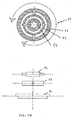
- the device comprises at least three arms 2 each pivoting about a pivot axis 3, said pivot axes being in the same plane here horizontal.
- An actuator 4 at least indirectly engages one of the two ends of each pivoting arm, each of these arms 2 being furthermore connected to a head 5 by means of connecting elements 6 articulated respectively on the head and on the arm. These joints are two degrees of freedom.
- the parallel type displacement device forms a kind of deformable truncated pyramid with triangular bases (for three axes of pivots) comprising at least three arms 2 each pivoting about a pivot axis 3 guided in rotation on at least one bearing 7, each of the arms being actuated by an actuator 4, said axes of pivots being optionally in the same plane called plane A of the large base and each of these arms being, in addition, connected to a head 5 forming a small base by via connecting elements 6 hinged respectively on the head and the arm with two degrees of freedom, the head always keeping its orientation and its inclination when the head moves in a plane. The head does not move in spherical motions.
- the axes of pivots are inclined downward towards the center. They could be inclined upward towards the center.
- connecting elements are shown as straight segments with one end of an arm in a median radial plane at the anchoring points of the connecting elements on the head but another configuration of all of these arms and elements of link (eg S-elements) might be suitable.
- This S shape could be independent of the architecture of the robot (orientation of the axes and position of the bearings).
- the arm can be straight, L, L truncated or curved.
- pivot pins 3 are mounted radial with a common intersection point disposed in the center of the large base. It is the same inclined axes that also meet at a point of intersection.
- Each arm ( figure 3 ) comprises two parts, a proximal portion 2a coaxial with the axis of rotation of the actuator and a distal portion 2b which extends along a second axis also radial forming an angle of 90 ° with the proximal portion.
- This distal portion connects to the proximal portion at a point near the intersection of the three pivot axes.
- the length of the imaginary arm is equal to the radius R defining the bulk of the arms.
- the end of the arm can therefore move approximately between + 90 ° and -90 ° relative to the so-called large base plane without encountering an obstacle.
- the amplitude of vertical displacement of the head from the neutral position, the arms being horizontal, is at most close to R the distance between the central point of the large base and the end of the arm.
- the pivot axes are angularly distributed in a pitch of 120 °.
- the angular position of the pivot axes can be non-regular, that is to say the angles are not necessarily all at 120 °. Of course if you have a robot with four arms, the angular disposition is different.
- the effective length of tilting of the connecting elements 6 is therefore the distance measured between the joints of these connecting elements to the arms and the center of the large base.
- the rotation of the arm about the pivot axis is not limited by an obstacle located in the central portion.
- An intermediate portion 2c connects the proximal portions 2a and 2b of the distal arm forming a truncated L which allows to leave a free space for possibly a gripper arm and to take into account the section of the arms.
- the pivot axis is always radial and the axis of rotation of the actuator perpendicularly attacks the proximal portion 2a of the arm which is extended by the distal portion which is at 90 ° forming an L whose corner of the L is outgoing .
- This distal portion is parallel to the axis of rotation of the actuator and therefore to the pivot axis.
- the three pivot axes form a triangle outside of which are mounted bearings 7.
- the arms also have a shape to position the head in neutral position in the vertical of the large base.
- the arm has an L shape with the reentrant corner facing the center.
- the proximal portion of the arm is coaxial with the pivot axis. Since the bearings 7 are carried outside the surface defined by the intersection of the pivot axes, this surface can be reduced to its limit value so that the effective length of the arm is substantially equal to the distance between the center of the large base and the end of the arm so substantially to the radius R defining the size.
- the pivot axes of the arms also form a triangle but the L-shaped arm has its corner of the outgoing L as in the figure 2 .
- the connecting elements are connected to the arm and to the head by articulations with two degrees of freedom such as universal joints.
- the head is always oriented in the same direction and always has the same inclination.
- the figure 10 shows a robot seen from above, the arms being rectilinear (the connecting elements are partially represented and the head is not shown).
- the displacement device comprises a gripper 10 with telescopic transmission.
- This gripper is mounted in the center (center of the pyramid with three sides when it is at its zero point, the arms being in the same plane as the pivot axes.).
- Rotation guidance for this gripper is performed on the head of the device.
- An additional actuator can rotate the gripper around its longitudinal axis.
- the upper part of this gripper can be supported on one of the arms.
- a coaxial connection can bring the power and control of the gripper through the arm.
- the gripper can be equipped with a suction cup, claws or any other means to grasp an object.
- the gripper is often mobile about its longitudinal axis and it is often composed of an actuator, a high articulation, a telescopic transmission (two rods sliding one inside the other), a low articulation (cardan or kneecap) positioned on the head and a gripping member.
- the high articulation is positioned above the plane A containing the arms when they are horizontal. That is, relative to the plane A, it is in the space opposite to that containing the head. Or the plane A is arranged between the upper articulation and the head.
- the gripper is fixed on the head 5 by a hinge 50 while its upper part (the rod 10A) slides freely in a guide means 51 orientable.
- This swiveling guide means is traversed by the gripper for axial guidance.
- the figure 12B shows an inner ring 52 through which the rod of the gripper.
- This inner ring 52 is pivotally mounted on an intermediate ring 53 itself pivotally mounted on an outer ring 54.
- This outer ring can be rotated.
- the axial guidance of the inner ring does not allow rotation of the rod in this axial guide and therefore when the outer ring rotates, the gripper rotates.
- the positioning of the axial guiding means is chosen according to the configuration of the robot knowing that the higher it is, the lower the working angle will be, but the longer the rod will be. Depending on the need, it will be chosen to reduce this angle by positioning the guide means above the plane A or to reduce the rod by moving it downwards.
- the actuators are, for example, electric motors known as "brushless” but it could be different means. They can be mounted at the end of axis but a toothed belt transmission or other allows to position them in a different plane.
- the head can be delta or radial.
- the transverse parts 80 which join the two points of low joints of the connecting elements to the head are arranged radially relative to the head.
- the point of attachment of the crosspieces is at the top of the triangle whereas for the figure 13C , the point of attachment is in the middle of the side of the triangle.
- the axes of these transverse pieces may be parallel or inclined with respect to the working plane of the head 5.
Landscapes
- Engineering & Computer Science (AREA)
- Robotics (AREA)
- Mechanical Engineering (AREA)
- Manipulator (AREA)
- Transmission Devices (AREA)
Description
- L'invention se rapporte à un dispositif de déplacement d'un objet dans l'espace.
- Pour déplacer un objet dans l'espace, on connaît les bras manipulateurs dont les articulations sont montées en série et ceux dont les articulations sont montées en parallèles. Ces bras sont encore appelés robots.
- Les robots types à articulations en série présentent l'inconvénient d'être relativement lourds et ont donc une inertie importante qui les empêche de travailler avec de grandes cadences.
- Les robots dits parallèles permettent des déplacements beaucoup plus rapides mais l'amplitude des mouvements est restreinte.
- L'invention se rapporte à un robot dit parallèle.
- On connaît précisément un tel robot
EP-A-250 470 - Le dispositif forme une sorte de pyramide déformable à bases triangulaires.
- Chaque actionneur est un moteur électrique dont l'axe de rotation est couplé à un bras (partie mobile) qui pivote autour de l'axe de rotation de l'actionneur.
- Les axes de pivots des bras forment un triangle et les éléments de liaison sont articulés respectivement à une tête (petite base) et à la partie mobile correspondante.
- Les articulations de ces éléments de liaison tant sur le bras que sur la tête sont à deux degrés de liberté.
- Ainsi, l'orientation et l'inclinaison de la tête restent inchangées dans l'espace.
- Un préhenseur à transmission télescopique est monté au centre du système.
- Un support central porte les actionneurs. Ce support central a sensiblement les dimensions définies par les trois axes de pivot.
- Les paliers de rotation des bras qui pivotent sont à cheval sur les axes de pivot et inscrits chacun pour moitié dans la surface définie par les axes de pivot des bras.
- Les bras sont, au moins dans leur partie terminale, radiaux et s'étendent vers l'extérieur du support central. L'amplitude de déplacement est minimisée par l'étendue du support qui doit avoir une taille suffisante pour porter les actionneurs et souvent un quatrième bras formant préhenseur reliant la grande base à la petite base. L'amplitude de mouvement est liée à la longueur utile du bras.
- L'encombrement est défini par le cercle passant par les extrémités des bras lorsque le système est en position neutre, les bras sont alors dans un même plan ici horizontal.
- On comprend bien que plus le support est de grande dimension pour un encombrement donné, plus la longueur des bras sera réduite. Ainsi pour un encombrement d'environ 550 millimètres de rayon, la longueur du bras est de 350 millimètres, la hauteur travail est ainsi de l'ordre de 300 à 350 millimètres.
- Pour augmenter la longueur des bras, pour un encombrement donné, il faut réduire la taille du support mais celui ci dépend de la taille des actionneurs et dans les configurations connues il ne peut être fortement réduit.
- On peut certes augmenter l'encombrement mais cela pose également des soucis d'implantation.
-
EP-A-1 129 829 , sur lequel repose le préambule de la revendication 1, montre un perfectionnement à ce type de dispositif apporté au montage du préhenseur à transmission télescopique monté au centre du système pour augmenter l'amplitude de déplacement de la transmission. Ce perfectionnement impose d'augmenter la taille du triangle pour dégager une ouverture plus large pour le préhenseur. - On connait des systèmes à déplacements sphériques et orientables d'une tête
WO 2004/106011 ,US2005/0159075 ouUS5847528 permettant l'orientation de la dite tête. La problématique est différente. Elle ne prend pas en compte la cadence et l'amplitude du mouvement de ces machines dont l'objectif est de prendre un objet posé sur un plan, de le déplacer très rapidement vers un autre plan, en changeant éventuellement son orientation par le mouvement du préhenseur en parallèle à son déplacement, puis de revenir saisir un autre objet (pick and place). - L'invention propose un dispositif qui apporte une plus grande amplitude de travail notamment dans le mouvement horizontal des bras.
- A cet effet, l'invention se rapporte à un dispositif de déplacement selon la revendication 1. Des mises en oeuvre de l'invention sont définies dans les revendications dépendantes.
- L'invention sera bien comprise à la lecture de la description ci-après faite à titre d'exemple non limitatif en regard du dessin qui représente :
-
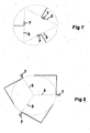
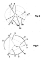
FIG 1 : Etat de la technique en vue de dessus simplifiée -
FIG 2 à FIG 4 : L'invention en vue de dessus simplifiée les axes de pivots étant radiaux. -
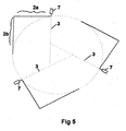
FIG 5 à FIG 7 : L'invention en vues de dessus simplifiées les axes de pivots formant un triangle -
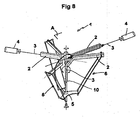
FIG 8 : Vue en perspective de l'invention. -
FIG 9 : Vue en perspective d'une variante de l'invention. -
FIG 10 : Vue de dessus d'un robot avec des bras droits. -
FIG 11A : Vue de face d'un exemple de robot -
FIG 11B : Coupe selon AA de lafigure 11A -
FIG 12A : Vue de face d'un robot avec un préhenseur -
FIG 12B : Vue d'un détail. -
FIG 13A,13B, 13C : Différentes têtes. - En se reportant à la
figure 8 , on voit un dispositif 1 de déplacement d'objets du type parallèle. - Ce dispositif permet de déplacer des objets avec une cadence élevée.
- Classiquement, le dispositif comprend au moins trois bras 2 pivotants chacun autour d'un axe 3 de pivot, lesdits axes de pivots étant dans un même plan ici horizontal.
- Un actionneur 4 engage au moins indirectement une des deux extrémités de chaque bras pivotant, chacun de ces bras 2 étant en outre relié à une tête 5 par l'intermédiaire d'éléments de liaison 6 articulés respectivement sur la tête et sur le bras. Ces articulations sont à deux degrés de liberté.
- Le dispositif de déplacement du type parallèle forme une sorte de pyramide tronquée déformable à bases triangulaires (pour trois axes de pivots) comprenant au moins trois bras 2 pivotants chacun autour d'un axe 3 de pivot guidé en rotation sur au moins un palier 7, chacun des bras étant actionné par un actionneur 4, lesdits axes de pivots étant éventuellement dans un même plan dite plan A de la grande base et chacun de ces bras étant, en outre, relié à une tête 5 formant une petite base par l'intermédiaire d'éléments de liaison 6 articulés respectivement sur la tête et sur le bras à deux degrés de liberté, la tête gardant toujours son orientation et son inclinaison lorsque la tête se déplace dans un plan. La tête ne se déplace pas selon des mouvements sphériques.
- A l'exception de la
figure 9 , les axes de pivots sont dans un même plan. - Pour la
figure 9 , les axes de pivots sont inclinés vers le bas en direction du centre. Ils pourraient être inclinés vers le haut en direction du centre. - Pour les
figures 1 à 7 on a représenté uniquement les bras et les paliers de pivots. - En rejetant vers l'extérieur les pivots d'articulation des bras et en conformant les bras et les éléments de liaison comme si ces bras avait une longueur utile proche de la distance entre le centre de la grande base et l'extrémité du bras sur laquelle s'articule l'élément de liaison, on va permettre d'augmenter la longueur opérationnelle des bras. En position que l'on appellera neutre, la tête se trouve à l'aplomb de la grande base et la force qui est exercée sur cette tête par un bras prolongé de son élément de liaison s'exerce dans un plan radial à la tête.
- Dans les dessins
figures 8 et9 , on a représenté les éléments de liaison sous forme de segments rectilignes avec une extrémité de bras dans un plan radial médian aux points d'ancrage des éléments de liaison sur la tête mais une autre configuration de l'ensemble de ces bras et des éléments de liaison (par exemple éléments en S) pourrait convenir. Cette forme en S pourrait être indépendante de l'architecture du robot (orientation des axes et position des paliers). - Dans des formes simples le bras peut être droit, en L , en L tronqué ou courbe.
- On va détailler ci-après quelques variantes.
- Dans une première version (
figure 2 ,3,4 ) les axes 3 de pivot sont montés radiaux avec un point d'intersection commun disposé au centre de la grande base. Il en est de même des axes inclinés qui se rejoignent aussi en un point d'intersection. - Cela permet d'avoir la longueur maximale de bras fictif.
- Chaque bras (
figure 3 ) comprend deux parties, une partie proximale 2a coaxiale à l'axe de rotation de l'actionneur et une partie distale 2b qui s'étend selon un deuxième axe également radial formant un angle de 90° avec la partie proximale. - Cette partie distale se raccorde à la partie proximale en un point proche de l'intersection des trois axes de pivot.
- Ainsi la longueur du bras fictif est égale au rayon R définissant l'encombrement des bras.
- L'extrémité du bras peut donc se déplacer approximativement entre +90° et -90° par rapport au plan dit de grande base sans rencontrer un obstacle.
- L'amplitude de déplacement vertical de la tête depuis la position neutre, les bras étant horizontaux, est au plus proche de R la distance entre le point central de la grande base et l'extrémité du bras.
- Les axes de pivot sont répartis angulairement selon un pas de 120°. La position angulaire des axes de pivot peut être non régulière, c'est-à-dire les angles ne sont pas nécessairement tous à 120°. Bien entendu si on dispose d'un robot à quatre bras, la disposition angulaire est différente.
- C'est sur la partie distale que s'articule l'élément de liaison.
- La longueur effective de basculement des éléments 6 de liaison est donc la distance mesurée entre les articulations de ces éléments de liaison aux bras et le centre de la grande base.
- Du fait de cette disposition, la rotation du bras autour de l'axe de pivot n'est pas limitée par un obstacle situé dans la partie centrale.
- On comprend bien que les actionneurs sont déplacés vers l'extérieur de la surface de croisement des axes.
- Une partie 2c intermédiaire relie les parties proximale 2a et distale 2b du bras formant un L tronqué qui permet de laisser une espace libre pour éventuellement un bras 10 préhenseur et pour tenir compte de la section des bras.
- Dans une seconde forme de réalisation du bras (
figure 2 ), l'axe de pivot est toujours radial et l'axe de rotation de l'actionneur attaque perpendiculairement la partie 2a proximale du bras qui se prolonge par la partie distale qui est à 90° formant un L dont le coin du L est sortant. Cette partie distale est parallèle à l'axe de rotation de l'actionneur et donc à l'axe de pivot. - Dans une 3ème variante et 4ième variante de réalisation, les axes 3 de pivots forment un triangle en dehors duquel sont montés les paliers 7.
- Les bras ont également une forme permettant de positionner la tête en position neutre à la verticale de la grande base.
- Dans l'exemple représenté
figure 6 , le bras à une forme en L avec le coin rentrant orienté vers le centre. - On a une configuration proche du dispositif de la
figure 3 mais la partie 2a proximale n'est pas radiale. - La partie proximale du bras est coaxiale à l'axe de pivot. Du fait que les paliers 7 sont reportés à l'extérieur de la surface définie par l'intersection des axes de pivots, cette surface peut être réduite à sa valeur limite en sorte que la longueur effective du bras est sensiblement égale à la distance entre le centre de la grande base et l'extrémité du bras donc sensiblement au rayon R définissant l'encombrement.
- Dans la quatrième variante
figure 5 , les axes de pivots des bras forment également un triangle mais le bras en L a son coin du L sortant comme dans lafigure 2 . - Comme on peut le voir sur les dessins
figure 8 ,9 , les éléments de liaison sont reliés au bras et à la tête par des articulations à deux degrés de liberté tels des cardans. - Ils se composent de deux profilés formant un parallélogramme déformable.
- Ainsi lors de ses déplacements, la tête reste toujours orientée dans la même direction et a toujours la même inclinaison.
- On a représenté également un robot avec des bras courbes
figure 4 ,7 . - La
figure 10 montre un robot vu de dessus, les bras étant rectilignes (les éléments de liaison sont partiellement représentés et la tête n'est pas représentée). - On voit entre autre que le dispositif de déplacement (
figures 8 ,9 ,11A ,11B ) comprend un préhenseur 10 à transmission télescopique. Ce préhenseur est monté en son centre (centre de la pyramide à trois cotés lorsque celle ci est en son point zéro, les bras étant dans le même plan que les axes de pivot.). - Un guidage en rotation, pour ce préhenseur est réalisé sur la tête du dispositif.
- Un actionneur supplémentaire peut faire tourner le préhenseur autour de son axe longitudinal.
- La partie haute de ce préhenseur peut prendre appui sur l'un des bras. Une connexion coaxiale peut amener la puissance et la commande du préhenseur au travers du bras.
- Le préhenseur peut être équipé d'une ventouse, de griffes ou tout autre moyen pour saisir un objet.
- Le préhenseur est souvent mobile autour de son axe longitudinal et il est souvent constitué d'un actionneur, d'une articulation haute, d'une transmission télescopique (deux tiges qui coulissent l'une dans l'autre), d'une articulation basse (cardan ou rotule) positionnée sur la tête et d'un organe de préhension.
- Avantageusement, l'articulation haute se positionne au dessus du plan A contenant les bras lorsqu'ils sont horizontaux. C'est à dire, par rapport au plan A, elle se situe dans l'espace opposé à celui contenant la tête. Ou encore le plan A est disposé entre l'articulation haute et la tête.
- On a représenté, en
figure 12A , un préhenseur 10 qui pourrait être monté sur un robot ne reprenant pas nécessairement les caractéristiques décrites, donc indépendant de la position des axes de pivot et des paliers. - Le préhenseur est fixé sur la tête 5 par une articulation 50 tandis que sa partie haute (la tige 10A) coulisse librement dans un moyen de guidage 51 orientable.
- Ce moyen de guidage orientable à la manière d'une rotule est traversé par le préhenseur pour un guidage axial. La
figure 12B montre une bague interne 52 traversée par la tige du préhenseur. - Cette bague 52 interne est montée basculante sur une bague intermédiaire 53 elle-même montée basculante sur une bague externe 54. Cette bague externe peut être entrainée en rotation. Le guidage axial de la bague interne ne permet pas la rotation de la tige dans ce guidage axial et par conséquent lorsque la bague externe tourne, le préhenseur tourne.
- Le positionnement du moyen de guidage axial est choisi selon la configuration du robot sachant que plus il est haut plus l'angle de travail sera faible mais plus la tige sera longue. Selon le besoin, on choisira de diminuer cet angle en positionnant le moyen de guidage au dessus du plan A ou de réduire la tige en le déplaçant vers le bas. Les actionneurs sont, par exemple, des moteurs électriques connus sous l'appellation « brushless » mais il pourrait s'agir de moyens différents. Ils peuvent être montés en bout d'axe mais une transmission par courroie crantée ou autre permet de les positionner dans un plan différent.
- Il peut être prévu que l'actionneur de ce préhenseur soit monté directement sur la tête mais cela augmente le poids donc l'inertie.
- On notera que sur le montage dit radial, il n'existe qu'un seul point du plan de déplacement de la dite tête où l'axe orthogonal au plan de la tête coïncide avec le point de croisement des axes de pivots.
- On notera également que la distance entre le centre de la tête et l'articulation entre le bras 2 et l'élément de liaison 6 varie lors du déplacement de la tête.
- La tête peut être à disposition delta ou radiale.
- On a représenté en
figures 13A, 13B, 13C des exemples de têtes 5. - Dans l'exemple
figure 13A , les pièces transversales 80 qui joignent les deux points d'articulations bas des éléments de liaison à la tête sont disposés radialement par rapport à la tête. - Dans les versions
figures 13B et 13C les axes longitudinaux de ces pièces transversales forment un triangle. - Sur la
figure 13B le point d'attache des pièces transversales est au sommet du triangle alors que pour lafigure 13C , le point d'attache est au milieu du coté du triangle. Les axes de ces pièces transversales peuvent être parallèles ou inclinés par rapport au plan de travail de la tête 5.
Claims (8)
- Dispositif de déplacement dans les trois dimensions de l'espace du type parallèle comprenant au moins trois bras (2) pivotants chacun autour d'un axe (3) de pivot guidé en rotation sur au moins un palier (7), chacun des bras étant actionné par un actionneur (4), et chacun de ces bras étant, en outre, relié à une tête (5) formant une petite base par l'intermédiaire d'éléments de liaison (6) articulés respectivement sur la tête (5) et sur le bras (2) à deux degrés de liberté, la tête gardant toujours son orientation et son inclinaison en se déplaçant dans un plan, les dits axes (3) de pivots étant dans un plan parallèle au plan de déplacement de la tête ou inclinés par rapport à un tel plan, ce dispositif de déplacement étant caractérisé en ce que les axes (3) de pivots définissent un point d'intersection commun ou que les paliers (7) de pivot des bras sont montés totalement à l'extérieur polygone délimité par les intersections deux à deux des axes de pivot ou de leurs projections sur le plan des paliers (7).
- Dispositif de déplacement selon la revendication 1 caractérisé en ce que les bras ont une forme de L.
- Dispositif de déplacement selon la revendication 2 caractérisé en ce que les bras ont une forme de L tronqué.
- Dispositif de déplacement selon la revendication 1 caractérisé en ce que les bras ont une forme courbe.
- Dispositif de déplacement selon l'une quelconque des revendications précédentes caractérisé en ce qu'il comprend un préhenseur à transmission télescopique.
- Dispositif de déplacement selon la revendication 5 caractérisé en ce qu'une connexion coaxiale amène la puissance et la commande du préhenseur au travers d'un bras.
- Dispositif de déplacement selon la revendication 5 comprenant pour le préhenseur, une articulation haute, une transmission télescopique, une articulation basse caractérisé en ce que le plan A contenant les bras lorsqu'ils sont horizontaux est situé entre l'articulation haute et la tête.
- Dispositif de déplacement selon l'une quelconque des revendications 1 à 7 caractérisé en ce qu'il comprend un préhenseur fixé sur la tête (5) par une articulation (50) tandis que sa partie haute coulisse librement dans un moyen de guidage (51) orientable
Applications Claiming Priority (1)
| Application Number | Priority Date | Filing Date | Title |
|---|---|---|---|
| FR0604169A FR2900857B1 (fr) | 2006-05-11 | 2006-05-11 | Robot manipulateur |
Publications (2)
| Publication Number | Publication Date |
|---|---|
| EP1854591A1 EP1854591A1 (fr) | 2007-11-14 |
| EP1854591B1 true EP1854591B1 (fr) | 2010-07-28 |
Family
ID=37682597
Family Applications (1)
| Application Number | Title | Priority Date | Filing Date |
|---|---|---|---|
| EP07350006A Not-in-force EP1854591B1 (fr) | 2006-05-11 | 2007-05-10 | Robot parallèle |
Country Status (6)
| Country | Link |
|---|---|
| EP (1) | EP1854591B1 (fr) |
| AT (1) | ATE475516T1 (fr) |
| DE (1) | DE602007008008D1 (fr) |
| DK (1) | DK1854591T3 (fr) |
| ES (1) | ES2349876T3 (fr) |
| FR (1) | FR2900857B1 (fr) |
Families Citing this family (13)
| Publication number | Priority date | Publication date | Assignee | Title |
|---|---|---|---|---|
| JP2008264904A (ja) * | 2007-04-17 | 2008-11-06 | Fanuc Ltd | パラレルリンク型作業装置 |
| DE102008009328A1 (de) | 2007-11-29 | 2009-06-04 | Weber Maschinenbau Gmbh Breidenbach | Roboter mit Delta-Kinematik |
| JP4598864B2 (ja) * | 2009-01-29 | 2010-12-15 | ファナック株式会社 | パラレルロボット |
| US8893578B2 (en) | 2009-02-13 | 2014-11-25 | Fanuc Corporation | Parallel robot provided with wrist section having three degrees of freedom |
| JP4659098B2 (ja) * | 2009-02-13 | 2011-03-30 | ファナック株式会社 | 3自由度を有する姿勢変更機構を備えたパラレルリンクロボット |
| JP5397856B2 (ja) * | 2009-08-28 | 2014-01-22 | 国立大学法人東京工業大学 | 6自由度パラレル機構 |
| CN102049786A (zh) * | 2009-11-05 | 2011-05-11 | 鸿富锦精密工业(深圳)有限公司 | 转动机构及使用该转动机构的机器人 |
| CN102069495B (zh) * | 2009-11-23 | 2014-01-22 | 鸿富锦精密工业(深圳)有限公司 | 并联机器人 |
| JP5785055B2 (ja) | 2011-11-07 | 2015-09-24 | Ntn株式会社 | リンク作動装置 |
| CN102490177B (zh) * | 2011-12-13 | 2014-04-30 | 天津大学 | 四自由度并联机器人 |
| DE102016215744A1 (de) | 2016-08-23 | 2018-03-01 | Hartmut Ilch | Industrieroboter |
| CN108161901B (zh) * | 2017-12-27 | 2020-02-14 | 中国地质大学(武汉) | 一种具有高偏转能力的两转并联机构 |
| TWI889292B (zh) * | 2023-04-17 | 2025-07-01 | 香港大學 | 用於手術持針器的立體定位器 |
Family Cites Families (4)
| Publication number | Priority date | Publication date | Assignee | Title |
|---|---|---|---|---|
| US5847528A (en) * | 1995-05-19 | 1998-12-08 | Canadian Space Agency | Mechanism for control of position and orientation in three dimensions |
| EP1930133B1 (fr) * | 2000-03-01 | 2014-04-09 | Robert Bosch GmbH | Robot pour la manipulation de produits dans un espace tridimensionnel |
| ITGE20030040A1 (it) * | 2003-05-30 | 2004-11-30 | Rezia Molfino | Meccanismo armillare per il supporto alla visione stereoscopica in ambienti sottomarini e ad alta resistenza idrodinamica |
| JP2005144627A (ja) * | 2003-11-18 | 2005-06-09 | Ntn Corp | リンク作動装置 |
-
2006
- 2006-05-11 FR FR0604169A patent/FR2900857B1/fr not_active Expired - Fee Related
-
2007
- 2007-05-10 EP EP07350006A patent/EP1854591B1/fr not_active Not-in-force
- 2007-05-10 AT AT07350006T patent/ATE475516T1/de not_active IP Right Cessation
- 2007-05-10 ES ES07350006T patent/ES2349876T3/es active Active
- 2007-05-10 DK DK07350006.8T patent/DK1854591T3/da active
- 2007-05-10 DE DE602007008008T patent/DE602007008008D1/de active Active
Also Published As
| Publication number | Publication date |
|---|---|
| ATE475516T1 (de) | 2010-08-15 |
| DK1854591T3 (da) | 2010-11-22 |
| EP1854591A1 (fr) | 2007-11-14 |
| ES2349876T3 (es) | 2011-01-12 |
| DE602007008008D1 (de) | 2010-09-09 |
| FR2900857B1 (fr) | 2008-10-17 |
| FR2900857A1 (fr) | 2007-11-16 |
Similar Documents
| Publication | Publication Date | Title |
|---|---|---|
| EP1854591B1 (fr) | Robot parallèle | |
| EP2125301B1 (fr) | Robot manipulateur compact | |
| EP2155553B1 (fr) | Dispositif de commande de pales d'helicoptere ou similaire | |
| EP0270469A1 (fr) | Machine robotisée, notamment pour la récolte de fruits | |
| CA2411915A1 (fr) | Bras de commande a deux branches en parallele | |
| FR3028441A1 (fr) | Dispositif et procede pour la manipulation d'articles tels que des emballages, des marchandises au detail ou autres | |
| EP1015192B1 (fr) | Machine robotisee pourvue d'au moins un bras a pantographe symetrique, par exemple pour la recolte de fruits ou le tri d'objets divers | |
| FR3000696A1 (fr) | Robot manipulateur translationnel pur a trois degres de liberte serie a encombrement reduit | |
| WO2015177154A1 (fr) | Nacelle pour robot parallèle destiné à agir sur un objet | |
| EP3994012B1 (fr) | Roue transformable adaptée pour franchir tout type de terrain et robot autonome équipé d'au moins une telle roue | |
| FR2559411A1 (fr) | Installation de manipulation de pieces, notamment pour le chargement et le dechargement de machines-outils | |
| EP0491613B1 (fr) | Dispositif manipulateur pour déplacer un objet, dans l'espace, parallèlement à lui-même | |
| EP3919234B1 (fr) | Dispositif pour deplacer des objets | |
| EP1099590B1 (fr) | Ensemble de captage de courant et véhicule ferroviaire correspondant | |
| EP0358563A1 (fr) | Machine à recolter les baies et notamment à vendanger | |
| CA3082924C (fr) | Vehicule destine a une ligne electrique | |
| EP0508841A1 (fr) | Bras d'essuie-glace, notamment pour véhicule à grande vitesse | |
| EP1072366A1 (fr) | Dispositif transporteur | |
| CA2325868C (fr) | Ensemble comprenant un premier chassis et un deuxieme chassis pendulant lateralement par rapport au premier chassis, et vehicule ferroviaire correspondant | |
| FR2771707A1 (fr) | Dispositif a plateaux cycliques de commande du pas des pales d'un rotor avec patins cylindriques glissant sur colonnes non-tournantes | |
| EP1820079A1 (fr) | Interface haptique a cables | |
| FR2940925A1 (fr) | Robot type parallele | |
| EP3381759A1 (fr) | Liaison mecanique a double liaison pivot, et vehicule ferroviaire comportant une telle liaison mecanique | |
| FR2900633A1 (fr) | Systeme de support de voile pour engin propulse a la voile | |
| FR3131861A1 (fr) | Dispositif de préhension adaptatif permettant de manipuler des éléments de carrosserie. |
Legal Events
| Date | Code | Title | Description |
|---|---|---|---|
| PUAI | Public reference made under article 153(3) epc to a published international application that has entered the european phase |
Free format text: ORIGINAL CODE: 0009012 |
|
| AK | Designated contracting states |
Kind code of ref document: A1 Designated state(s): AT BE BG CH CY CZ DE DK EE ES FI FR GB GR HU IE IS IT LI LT LU LV MC MT NL PL PT RO SE SI SK TR |
|
| AX | Request for extension of the european patent |
Extension state: AL BA HR MK YU |
|
| 17P | Request for examination filed |
Effective date: 20080502 |
|
| 17Q | First examination report despatched |
Effective date: 20080602 |
|
| AKX | Designation fees paid |
Designated state(s): AT BE BG CH CY CZ DE DK EE ES FI FR GB GR HU IE IS IT LI LT LU LV MC MT NL PL PT RO SE SI SK TR |
|
| GRAP | Despatch of communication of intention to grant a patent |
Free format text: ORIGINAL CODE: EPIDOSNIGR1 |
|
| RAP1 | Party data changed (applicant data changed or rights of an application transferred) |
Owner name: MAREL FOOD SYSTEMS HF. |
|
| RIN1 | Information on inventor provided before grant (corrected) |
Inventor name: CHENU, JEAN-MARIE |
|
| GRAS | Grant fee paid |
Free format text: ORIGINAL CODE: EPIDOSNIGR3 |
|
| GRAA | (expected) grant |
Free format text: ORIGINAL CODE: 0009210 |
|
| AK | Designated contracting states |
Kind code of ref document: B1 Designated state(s): AT BE BG CH CY CZ DE DK EE ES FI FR GB GR HU IE IS IT LI LT LU LV MC MT NL PL PT RO SE SI SK TR |
|
| REG | Reference to a national code |
Ref country code: GB Ref legal event code: FG4D Free format text: NOT ENGLISH |
|
| REG | Reference to a national code |
Ref country code: CH Ref legal event code: EP |
|
| REG | Reference to a national code |
Ref country code: IE Ref legal event code: FG4D Free format text: LANGUAGE OF EP DOCUMENT: FRENCH |
|
| REF | Corresponds to: |
Ref document number: 602007008008 Country of ref document: DE Date of ref document: 20100909 Kind code of ref document: P |
|
| REG | Reference to a national code |
Ref country code: NL Ref legal event code: T3 |
|
| REG | Reference to a national code |
Ref country code: CH Ref legal event code: NV Representative=s name: ISLER & PEDRAZZINI AG |
|
| REG | Reference to a national code |
Ref country code: SE Ref legal event code: TRGR |
|
| REG | Reference to a national code |
Ref country code: DK Ref legal event code: T3 |
|
| LTIE | Lt: invalidation of european patent or patent extension |
Effective date: 20100728 |
|
| REG | Reference to a national code |
Ref country code: ES Ref legal event code: FG2A Effective date: 20101229 |
|
| PG25 | Lapsed in a contracting state [announced via postgrant information from national office to epo] |
Ref country code: AT Free format text: LAPSE BECAUSE OF FAILURE TO SUBMIT A TRANSLATION OF THE DESCRIPTION OR TO PAY THE FEE WITHIN THE PRESCRIBED TIME-LIMIT Effective date: 20100728 Ref country code: FI Free format text: LAPSE BECAUSE OF FAILURE TO SUBMIT A TRANSLATION OF THE DESCRIPTION OR TO PAY THE FEE WITHIN THE PRESCRIBED TIME-LIMIT Effective date: 20100728 Ref country code: LT Free format text: LAPSE BECAUSE OF FAILURE TO SUBMIT A TRANSLATION OF THE DESCRIPTION OR TO PAY THE FEE WITHIN THE PRESCRIBED TIME-LIMIT Effective date: 20100728 |
|
| PG25 | Lapsed in a contracting state [announced via postgrant information from national office to epo] |
Ref country code: IS Free format text: LAPSE BECAUSE OF FAILURE TO SUBMIT A TRANSLATION OF THE DESCRIPTION OR TO PAY THE FEE WITHIN THE PRESCRIBED TIME-LIMIT Effective date: 20101128 Ref country code: PT Free format text: LAPSE BECAUSE OF FAILURE TO SUBMIT A TRANSLATION OF THE DESCRIPTION OR TO PAY THE FEE WITHIN THE PRESCRIBED TIME-LIMIT Effective date: 20101129 Ref country code: SI Free format text: LAPSE BECAUSE OF FAILURE TO SUBMIT A TRANSLATION OF THE DESCRIPTION OR TO PAY THE FEE WITHIN THE PRESCRIBED TIME-LIMIT Effective date: 20100728 Ref country code: BG Free format text: LAPSE BECAUSE OF FAILURE TO SUBMIT A TRANSLATION OF THE DESCRIPTION OR TO PAY THE FEE WITHIN THE PRESCRIBED TIME-LIMIT Effective date: 20101028 Ref country code: CY Free format text: LAPSE BECAUSE OF FAILURE TO SUBMIT A TRANSLATION OF THE DESCRIPTION OR TO PAY THE FEE WITHIN THE PRESCRIBED TIME-LIMIT Effective date: 20100728 Ref country code: PL Free format text: LAPSE BECAUSE OF FAILURE TO SUBMIT A TRANSLATION OF THE DESCRIPTION OR TO PAY THE FEE WITHIN THE PRESCRIBED TIME-LIMIT Effective date: 20100728 |
|
| REG | Reference to a national code |
Ref country code: IE Ref legal event code: FD4D |
|
| PG25 | Lapsed in a contracting state [announced via postgrant information from national office to epo] |
Ref country code: GR Free format text: LAPSE BECAUSE OF FAILURE TO SUBMIT A TRANSLATION OF THE DESCRIPTION OR TO PAY THE FEE WITHIN THE PRESCRIBED TIME-LIMIT Effective date: 20101029 Ref country code: LV Free format text: LAPSE BECAUSE OF FAILURE TO SUBMIT A TRANSLATION OF THE DESCRIPTION OR TO PAY THE FEE WITHIN THE PRESCRIBED TIME-LIMIT Effective date: 20100728 |
|
| PG25 | Lapsed in a contracting state [announced via postgrant information from national office to epo] |
Ref country code: IE Free format text: LAPSE BECAUSE OF FAILURE TO SUBMIT A TRANSLATION OF THE DESCRIPTION OR TO PAY THE FEE WITHIN THE PRESCRIBED TIME-LIMIT Effective date: 20100728 |
|
| PG25 | Lapsed in a contracting state [announced via postgrant information from national office to epo] |
Ref country code: SK Free format text: LAPSE BECAUSE OF FAILURE TO SUBMIT A TRANSLATION OF THE DESCRIPTION OR TO PAY THE FEE WITHIN THE PRESCRIBED TIME-LIMIT Effective date: 20100728 Ref country code: RO Free format text: LAPSE BECAUSE OF FAILURE TO SUBMIT A TRANSLATION OF THE DESCRIPTION OR TO PAY THE FEE WITHIN THE PRESCRIBED TIME-LIMIT Effective date: 20100728 Ref country code: EE Free format text: LAPSE BECAUSE OF FAILURE TO SUBMIT A TRANSLATION OF THE DESCRIPTION OR TO PAY THE FEE WITHIN THE PRESCRIBED TIME-LIMIT Effective date: 20100728 Ref country code: CZ Free format text: LAPSE BECAUSE OF FAILURE TO SUBMIT A TRANSLATION OF THE DESCRIPTION OR TO PAY THE FEE WITHIN THE PRESCRIBED TIME-LIMIT Effective date: 20100728 |
|
| PLBE | No opposition filed within time limit |
Free format text: ORIGINAL CODE: 0009261 |
|
| STAA | Information on the status of an ep patent application or granted ep patent |
Free format text: STATUS: NO OPPOSITION FILED WITHIN TIME LIMIT |
|
| 26N | No opposition filed |
Effective date: 20110429 |
|
| REG | Reference to a national code |
Ref country code: DE Ref legal event code: R097 Ref document number: 602007008008 Country of ref document: DE Effective date: 20110429 |
|
| PG25 | Lapsed in a contracting state [announced via postgrant information from national office to epo] |
Ref country code: MC Free format text: LAPSE BECAUSE OF NON-PAYMENT OF DUE FEES Effective date: 20110531 Ref country code: MT Free format text: LAPSE BECAUSE OF FAILURE TO SUBMIT A TRANSLATION OF THE DESCRIPTION OR TO PAY THE FEE WITHIN THE PRESCRIBED TIME-LIMIT Effective date: 20100728 |
|
| PG25 | Lapsed in a contracting state [announced via postgrant information from national office to epo] |
Ref country code: LU Free format text: LAPSE BECAUSE OF NON-PAYMENT OF DUE FEES Effective date: 20110510 |
|
| PG25 | Lapsed in a contracting state [announced via postgrant information from national office to epo] |
Ref country code: TR Free format text: LAPSE BECAUSE OF FAILURE TO SUBMIT A TRANSLATION OF THE DESCRIPTION OR TO PAY THE FEE WITHIN THE PRESCRIBED TIME-LIMIT Effective date: 20100728 |
|
| PG25 | Lapsed in a contracting state [announced via postgrant information from national office to epo] |
Ref country code: HU Free format text: LAPSE BECAUSE OF FAILURE TO SUBMIT A TRANSLATION OF THE DESCRIPTION OR TO PAY THE FEE WITHIN THE PRESCRIBED TIME-LIMIT Effective date: 20100728 |
|
| REG | Reference to a national code |
Ref country code: FR Ref legal event code: PLFP Year of fee payment: 9 |
|
| PGFP | Annual fee paid to national office [announced via postgrant information from national office to epo] |
Ref country code: CH Payment date: 20150512 Year of fee payment: 9 Ref country code: DE Payment date: 20150525 Year of fee payment: 9 Ref country code: SE Payment date: 20150522 Year of fee payment: 9 Ref country code: ES Payment date: 20150512 Year of fee payment: 9 Ref country code: DK Payment date: 20150526 Year of fee payment: 9 Ref country code: GB Payment date: 20150526 Year of fee payment: 9 |
|
| PGFP | Annual fee paid to national office [announced via postgrant information from national office to epo] |
Ref country code: FR Payment date: 20150601 Year of fee payment: 9 Ref country code: BE Payment date: 20150519 Year of fee payment: 9 Ref country code: IT Payment date: 20150513 Year of fee payment: 9 Ref country code: NL Payment date: 20150519 Year of fee payment: 9 |
|
| PG25 | Lapsed in a contracting state [announced via postgrant information from national office to epo] |
Ref country code: BE Free format text: LAPSE BECAUSE OF NON-PAYMENT OF DUE FEES Effective date: 20160531 |
|
| REG | Reference to a national code |
Ref country code: DE Ref legal event code: R119 Ref document number: 602007008008 Country of ref document: DE |
|
| REG | Reference to a national code |
Ref country code: CH Ref legal event code: PL |
|
| REG | Reference to a national code |
Ref country code: DK Ref legal event code: EBP Effective date: 20160531 |
|
| REG | Reference to a national code |
Ref country code: NL Ref legal event code: MM Effective date: 20160601 |
|
| GBPC | Gb: european patent ceased through non-payment of renewal fee |
Effective date: 20160510 |
|
| PG25 | Lapsed in a contracting state [announced via postgrant information from national office to epo] |
Ref country code: CH Free format text: LAPSE BECAUSE OF NON-PAYMENT OF DUE FEES Effective date: 20160531 Ref country code: LI Free format text: LAPSE BECAUSE OF NON-PAYMENT OF DUE FEES Effective date: 20160531 |
|
| PG25 | Lapsed in a contracting state [announced via postgrant information from national office to epo] |
Ref country code: NL Free format text: LAPSE BECAUSE OF NON-PAYMENT OF DUE FEES Effective date: 20160601 Ref country code: IT Free format text: LAPSE BECAUSE OF NON-PAYMENT OF DUE FEES Effective date: 20160510 Ref country code: SE Free format text: LAPSE BECAUSE OF NON-PAYMENT OF DUE FEES Effective date: 20160511 |
|
| REG | Reference to a national code |
Ref country code: FR Ref legal event code: ST Effective date: 20170131 |
|
| PG25 | Lapsed in a contracting state [announced via postgrant information from national office to epo] |
Ref country code: FR Free format text: LAPSE BECAUSE OF NON-PAYMENT OF DUE FEES Effective date: 20160531 Ref country code: DE Free format text: LAPSE BECAUSE OF NON-PAYMENT OF DUE FEES Effective date: 20161201 |
|
| PG25 | Lapsed in a contracting state [announced via postgrant information from national office to epo] |
Ref country code: DK Free format text: LAPSE BECAUSE OF NON-PAYMENT OF DUE FEES Effective date: 20160531 Ref country code: GB Free format text: LAPSE BECAUSE OF NON-PAYMENT OF DUE FEES Effective date: 20160510 |
|
| PG25 | Lapsed in a contracting state [announced via postgrant information from national office to epo] |
Ref country code: ES Free format text: LAPSE BECAUSE OF NON-PAYMENT OF DUE FEES Effective date: 20160511 |
|
| REG | Reference to a national code |
Ref country code: ES Ref legal event code: FD2A Effective date: 20181204 |