EP1854199B1 - Moteur du type a double rotor - Google Patents
Moteur du type a double rotor Download PDFInfo
- Publication number
- EP1854199B1 EP1854199B1 EP06702890.2A EP06702890A EP1854199B1 EP 1854199 B1 EP1854199 B1 EP 1854199B1 EP 06702890 A EP06702890 A EP 06702890A EP 1854199 B1 EP1854199 B1 EP 1854199B1
- Authority
- EP
- European Patent Office
- Prior art keywords
- core
- insulator
- rotor
- type motor
- rotor type
- Prior art date
- Legal status (The legal status is an assumption and is not a legal conclusion. Google has not performed a legal analysis and makes no representation as to the accuracy of the status listed.)
- Active
Links
- 230000009977 dual effect Effects 0.000 title claims description 39
- 239000012212 insulator Substances 0.000 claims description 85
- 238000005192 partition Methods 0.000 claims description 35
- 238000000465 moulding Methods 0.000 claims description 26
- 238000001816 cooling Methods 0.000 claims description 22
- 238000005406 washing Methods 0.000 claims description 22
- 239000002184 metal Substances 0.000 claims description 19
- 229910052751 metal Inorganic materials 0.000 claims description 19
- 230000002787 reinforcement Effects 0.000 claims description 12
- 230000003014 reinforcing effect Effects 0.000 claims description 8
- 235000005824 Zea mays ssp. parviglumis Nutrition 0.000 claims description 3
- 235000002017 Zea mays subsp mays Nutrition 0.000 claims description 3
- 235000005822 corn Nutrition 0.000 claims description 3
- 239000011810 insulating material Substances 0.000 claims 3
- 240000008042 Zea mays Species 0.000 claims 1
- 238000004049 embossing Methods 0.000 description 8
- 238000000034 method Methods 0.000 description 8
- 239000011347 resin Substances 0.000 description 8
- 229920005989 resin Polymers 0.000 description 8
- XLYOFNOQVPJJNP-UHFFFAOYSA-N water Substances O XLYOFNOQVPJJNP-UHFFFAOYSA-N 0.000 description 5
- 230000000694 effects Effects 0.000 description 3
- RYGMFSIKBFXOCR-UHFFFAOYSA-N Copper Chemical compound [Cu] RYGMFSIKBFXOCR-UHFFFAOYSA-N 0.000 description 2
- 241000209149 Zea Species 0.000 description 2
- 210000003298 dental enamel Anatomy 0.000 description 2
- 238000001746 injection moulding Methods 0.000 description 2
- 239000000463 material Substances 0.000 description 2
- 238000004804 winding Methods 0.000 description 2
- 239000003599 detergent Substances 0.000 description 1
- 238000007599 discharging Methods 0.000 description 1
- 238000002347 injection Methods 0.000 description 1
- 239000007924 injection Substances 0.000 description 1
- 230000002452 interceptive effect Effects 0.000 description 1
- 238000002844 melting Methods 0.000 description 1
- 230000008018 melting Effects 0.000 description 1
- 238000013021 overheating Methods 0.000 description 1
- 239000000243 solution Substances 0.000 description 1
- 238000009987 spinning Methods 0.000 description 1
- 239000000725 suspension Substances 0.000 description 1
Images


Classifications
-
- D—TEXTILES; PAPER
- D06—TREATMENT OF TEXTILES OR THE LIKE; LAUNDERING; FLEXIBLE MATERIALS NOT OTHERWISE PROVIDED FOR
- D06F—LAUNDERING, DRYING, IRONING, PRESSING OR FOLDING TEXTILE ARTICLES
- D06F37/00—Details specific to washing machines covered by groups D06F21/00 - D06F25/00
- D06F37/30—Driving arrangements
- D06F37/304—Arrangements or adaptations of electric motors
-
- H—ELECTRICITY
- H02—GENERATION; CONVERSION OR DISTRIBUTION OF ELECTRIC POWER
- H02K—DYNAMO-ELECTRIC MACHINES
- H02K1/00—Details of the magnetic circuit
- H02K1/06—Details of the magnetic circuit characterised by the shape, form or construction
- H02K1/12—Stationary parts of the magnetic circuit
- H02K1/14—Stator cores with salient poles
- H02K1/146—Stator cores with salient poles consisting of a generally annular yoke with salient poles
- H02K1/148—Sectional cores
-
- H—ELECTRICITY
- H02—GENERATION; CONVERSION OR DISTRIBUTION OF ELECTRIC POWER
- H02K—DYNAMO-ELECTRIC MACHINES
- H02K16/00—Machines with more than one rotor or stator
- H02K16/02—Machines with one stator and two or more rotors
-
- H—ELECTRICITY
- H02—GENERATION; CONVERSION OR DISTRIBUTION OF ELECTRIC POWER
- H02K—DYNAMO-ELECTRIC MACHINES
- H02K21/00—Synchronous motors having permanent magnets; Synchronous generators having permanent magnets
- H02K21/12—Synchronous motors having permanent magnets; Synchronous generators having permanent magnets with stationary armatures and rotating magnets
-
- H—ELECTRICITY
- H02—GENERATION; CONVERSION OR DISTRIBUTION OF ELECTRIC POWER
- H02K—DYNAMO-ELECTRIC MACHINES
- H02K7/00—Arrangements for handling mechanical energy structurally associated with dynamo-electric machines, e.g. structural association with mechanical driving motors or auxiliary dynamo-electric machines
- H02K7/14—Structural association with mechanical loads, e.g. with hand-held machine tools or fans
Definitions
- the present invention relates to a motor, and more particularly, to a dual rotor type brushless DC (hereinafter, BLDC) motor which improves torque by means of dually mounting rotors in both sides of a stator of an appliance such as a washing machine.
- BLDC brushless DC
- drum type washing method detergent, washing water and the laundry are introduced and washing is performed by using a friction power between a rotating drum and the laundry after receiving a drive force of a motor.
- the drum type washing method has not only an enhanced washing efficiency but also little laundry damage and laundry tangle.
- a conventional drum type washing machine is classified into an indirect drive type in which driving force of a motor is indirectly transmitted to a drum through a belt tied around a motor pulley and a drum pulley, and a direct drive type in which driving force of a motor is directly transmitted to a drum by reason that a rotor of a BLDC motor is directly connected to a drum.
- the indirect method has some problems of energy loss and a lot of noise, which are caused in a process transmitting the driving force.
- FIG. 1 a related art drum type washing machine will be described.
- a tub 2 is mounted within a cabinet 1, and a drum 3 is rotatably mounted in a center of the tub 2.
- a motor having a stator 6 and a rotor 5 is mounted in rear of the tub 2.
- the stator 6 is secured on a rear wall of the tub, and the rotor 5 passes through the tub and is connected to the drum 3 by a shaft with covering the stator 6.
- Magnets are alternatively provided on an inner circumferential surface of the rotor 5 in opposite poles.
- a tub supporter made of metal which has almost the same appearance of an exterior of the rear wall of the tub 2 is interposed between the rear wall of the tub and the stator for maintaining concentricity of the stator as well as supporting load of the stator by being secured to the rear wall of the tub.
- a door 7 is provided in front of the cabinet 1, and a gasket 8 is provided between the door 7 and the tub 2.
- a suspension spring 9a is provided between an inner surface of the cabinet's upper portion and an outer circumferential surface of the tub's upper portion for supporting the tub 2.
- a friction damper 9b is provided between an inner surface of the cabinet's lower portion and an outer circumferential surface of the tub's lower portion for dampening vibration of the tub 2 generated in a spinning cycle.
- FIG. 2 is an enlarged sectional view of the motor.
- the stator 6 is secured to a bearing housing 2a on a rear surface of the tub 2, and the rotor 5 is rotoatably mounted in an outer of the stator 6.
- a first end of a shaft 4 is secured to a center of the rotor 5, and a second thereof is secured to a rear surface of the drum 3.
- a permanent magnet 5a is mounted on the inner circumferential surface of the rotor 5, and the stator 6 is employed as an electromagnet due to a core and a coil wound on an outer circumferential surface of the core.
- the rotor 5 rotates due to rotating magnetic field created between the permanent magnet and the electromagnet, and rotation torque of the rotor 5 is transmitted to the drum 3 through the shaft 4.
- the above related art motor has a limitation of increasing output and power, because it uses one rotor.
- output torque and power of a motor should be increased to rotate a drum of a washing machine as capacity thereof is enlarged.
- the size of the rotor and stator is also enlarged so as to increase the output of the motor. Thereby, it may cause a problem that size and weight of a motor should be increased.
- US 2004/245878 A1 discloses a dual rotor type motor, which is applied to an appliance such as a washing machine.
- An object of the present invention devised to solve the problem is to provide a dual rotor motor having an efficient structure which can beautifully enhance output of a motor without increasing a size and weight thereof.
- a dual rotor type motor according to the present invention has an advantageous effect that the output of the motor may be enhanced without enlarging the size and weight of the motor, because the inner rotor and the outer rotor are provided in the inner portion and outer portion of the stator according to the present invention.
- stator it is easy to secure to an appliance such as a washing machine, because the core of the stator and the insulator are supported by the molding part.
- the molding part is surrounding the core of the stator, the insulator and the coil, water-proof efficiency of the stator may be enhanced.
- water-proof efficiency of the stator may be enhanced.
- air for cooling is ventilated smoothly to radiate the heat of the motor more efficiently even in rotating/ reverse-rotating the shaft of the motor by agitating.
- the inner space of the inner rotor may be cooled efficiently, because air can flow into the inner and outer side of the inner rotor through the intervals on the portion having the outer rotor and the inner rotor fastened thereto by the embossing of the base of the outer rotor.
- FIGS. 3 through 9 a first embodiment of a dual rotor type motor according to the present invention will be described.
- the dual rotor type motor of the present invention is applied to a washing machine.
- the dual rotor type motor of the present invention may be applied not only to a washing machine but also to other appliances such as an air conditioner.
- a shaft 4 is rotatably mounted on a rear surface center of a tub 2 (see FIG. 1 ) for driving a drum 3.
- the shaft 4 is supported by a bearing 2b within a bearing housing 2a provided in rear of the tub 2.
- a motor is mounted on the bearing housing 2a for driving the shaft 4.
- the motor is provided so as to maintain a predetermined distance between a stator 30 secured on the bearing housing 2a and an inner/outer surface of the stator 30, and there are an outer rotor 10 and an inner rotor 20 having a first/second end of the shaft 4 secured thereto.
- the outer rotor 10 and the inner rotor 20 are made of metal, but may be made of injection molded resin.
- the outer rotor 10 is formed as a disk shape and has a bushing 40 of resin material secured to a center thereof.
- the bushing 40 is fastened to the shaft 4.
- the bushing 40 is secured to a center of the outer rotor 10 by securing means such as a bolt 42, and may be formed on the outer rotor as one body.
- the bushing 40 has a hole the shaft 4 is inserted to and serration part 41 formed on an inner circumferential surface of the hole for being connected with a serration part 4a on an outer circumferential surface of the shaft 4.
- the outer rotor 10 includes an outer rotor frame 11 of a disk shape, an outer magnets 12 having an S-pole and N-pole thereof alternatively disposed in the outer rotor frame 11, and a cooling hole 13.
- the inner rotor 20 includes an inner rotor frame 21 of an annular shape concentrically secured to the outer rotor 10, and an inner magnets 22 provided along an outer circumferential surface of the inner rotor frame 22.
- An S-pole and an N-pole of the inner magnets 22 are also alternatively disposed.
- the outer rotor frame 11 includes a base 11a, an extension 11b extending from an outer circumferential surface toward a perpendicular direction of the base 11a.
- Each outer magnets 12 is provided on an inner circumferential surface of the extension 11b along a radius direction.
- an embossing 14 is formed on the base 11a, which is embossed upwardly at a predetermined height by press finishing.
- a plurality of the embossings 14 is formed along a circumferential direction of the base 11a at a predetermined distance.
- a caulking part 15 is formed by press finishing and caulking at a portion where the embossing 14 and the inner rotor 20 are contacted. Thereby, the inner rotor 20 is secured to an upper surface of the base 11a.
- the portion where the embossing and the inner rotor 20 are contacted is secured by a calking hole part 15.
- the calking hole part 15 is formed by press finishing, which uses a press die, and caulking.
- the outer rotor 10 and the inner rotor 20 are positioned on the press die for forming the caulking hole part 102, the inner circumferential surface of the inner rotor 20 and the outer circumferential surface of the outer rotor are aligned by a align device, and automatically each center thereof is in accordance. That is, the outer rotor 10 and the inner rotor 20 are concentrically secured.
- the caulking hole part 14 has a hole passing through a lower surface of the inner rotor 20 from the base 11a, and a rim of the hole is compressed and banded. Thereby, the lower surface of the inner rotor 20 is clapped between a caulking 16 and the base 11a to be secured.
- a cooling hole part 13 is provided at the base 11a for allow air cooling the motor to pass through, and preferably the cooling hole part 13 is formed at an exact outside of the outer circumferential surface of the inner rotor 20.
- the cooling hole part 13 includes a cooling hole 13a formed along a circumferential direction of the base 11a at a predetermined distance for allowing air to pass through, and a guide part 13b projected along a rim of the cooling hole 13a at a predetermined height.
- air may pass through the cooling hole 13a for being discharged outside of the outer rotor 10 or drawn inside. Also, air in the inner rotor 20 passes through the space between the lower surface of the inner rotor 20 and the base 11a, and after that the air may be discharged outside through the cooling hole 13a. By the above air circulation, heat generated from the motor may be radiated.
- the guide part 13b is inclined toward an inside of the cooling hole 13a for softening air steam line passing through the cooling hole 13a.
- a section of the guide part may be formed variously such as a round-shape.
- the guide part 13b of the cooling hole part 13 is formed as a separate piece, but preferably as one body with the base 11a, for example, by lancing.
- the cooling hole part 13 is formed at the outer rotor 10, even in case that the motor rotates/counter-rotates, air is ventilated through the cooling hole part to prevent the motor's overheating.
- the stator 30 includes a plurality of single-partition cores 31, an insulator 32 of insulating resin for surrounding the single-partition cores 31, a coil 34 wound on an outside of the insulator 32, and a molding part 33 of resin made by means of insert molding for surrounding and supporting the insulator 32 and the coil 34 as one body.
- the molding part 33 is in a circular shape, and made each single-partition core 31 exposed outside on each inner/outer surface thereof facing the magnets 12 and 22 of the outer rotor 10 and the inner rotor.
- a fixing part 35 is formed at an end of the molding part 33 adjacent to the bearing housing 2a as one body extending toward an inner circumferential direction for being fastened to the bearing housing 2a.
- a plurality of fastening holes 35a is formed at an inner end of the fixing part 33 at a predetermined distance, and the fastening hole 35 is corresponding to the bolt fastening hole 2c of the bearing housing.
- the stator 30 should be secured to the shaft 4 with a precise concentricity.
- a plurality of position-determining protrusions is further projectedly formed at a first side of the bolt fastening hole 2c of the bearing housing 2a at a predetermined distance.
- position-determining recesses are formed for making the position-determining protrusions 2d inserted tightly thereto.
- the position-determining recess may be formed as a through hole passing through the fixing part 35.
- the bearing housing 2a may have position-determining recesses, and the fixing part 35 may have position-determining protrusions.
- the position-determining protrusion 2d includes a body having a regular diameter, and a guide formed at an end of the body as a corn shape for helping the position-determining protrusion inserted to the position-determining recess 35b more smoothly.
- the position-determining recess 35b and the position-determining protrusion 2d are same in size and appearance for fastening the position-determining protrusion 2d tight enough not to move the position-determining protrusion. That is, the position-determining recess 35b has a portion having the body of the position-determining protrusion 2d inserted thereto, of which a diameter is regular, whereas, a portion having the end of the guide inserted thereto, which is inclined in a corn shape.
- the position-determining recess 35d of the fixing part 35 is smaller than the fastening hole 35a in diameter.
- a portion around the fastening hole of the fixing part 35 is a little bit more projected than the other portions.
- a plurality of strength enforcement ribs 33a is formed on an outer surface of the molding part 33 for reinforcing strength.
- the strength enforcement rib 33a is extending to an outer surface of the fixing part 35.
- An enforcement rib 35c is also formed on an inner surface of the fixing part 35 or enforcing the strength of the fixing part 35 in a range of not interfering with the rotation of the inner rotor 20.
- a metal enforcement bracket of an annular shape (not shown) is in a close contact with the inner or outer surface of the molding part 33 without the strength enforcement rib 35c to enforcing the strength of the molding part 33.
- a connector 37 is formed in the molding part 33 as one body for supplying power to each coil 34 of the stator 30.
- a hall sensor securing part 38 is formed as one body in a first side of the molding part 33, which has a hall sensor unit secured thereon for detecting a position of the magnets 22 of the inner rotor 20.
- An insert hole 38a is formed at the hall sensor securing part 38 for having a sensor terminal 51 of the hall sensor unit 50 inserted thereto.
- the insert hole 38a may pass through the inner surface of the molding part 33, or may be recessed enough to be adjacent to the magnets 22 of the inner rotor 20.
- the sensor terminal 51 may detect the position of the magnets 12 of the outer rotor 10.
- a plurality of cooling holes is formed in the molding part 33 to be passed through outside for discharging heat generated when driving the motor outside.
- the core of the stator 30 is a single-partition core 31.
- the single-partition core 31 is formed in a T-shape.
- the single-partition cores 31 of a T-shape may be used independently or may be used in a pair facing each other.
- the insulator 32 includes a lower insulator 32a and an upper insulator 32b fastened to an upper portion of the lower insulator 32a.
- the lower and upper insulator 32a and 32b may be fastened in a hook fastening mechanism and alternatively may be formed by insert-molding as one body to cover the single-partition cores 31.
- Each of the upper and lower insulators 32a and 32b includes a core holder 32c for holding each single-partition core 31, and a connecting part 32d for connecting each inner end of the core holder together as well as making the insulator a circular shape.
- the connecting part 32d may connect two outer ends of each core holder 32c to connect the core holders 32 as one body.
- the core holder 32c has an inner/outer end thereof opened to expose a shoe 31a of both ends outside.
- the coil 34 wound around each core holder 32c in the insulator 32 may be an enameled copper wire.
- the stator 30 with the above configurations is manufactured as follows.
- a single-partition core 31 is seated on each core holder 32c of the lower insulator 32, and the upper insulator 32b is fastened to the upper portion of the lower insulator 32a.
- a coil 34 is wound around each core holder 32c of the insulator 32 by means of a winding machine.
- the molding part 33 is formed.
- the melting point of the resin is lower than that of the enamel of the coil 34 as well as that of the insulator material, so that the resin of the molder 33 may not damage the enamel of the coil 34 and the insulator 32.
- the lower and upper insulator 32 may be not connected each other and independently separated. In that case, since the single-partition core 31 and the insulator are discrete components, there may be an advantageous effect that the coil 34 is wound very fast without interference of the other insulator.
- the single-partition core and the insulator are discrete components
- the single-partition core is divided into a first single-partition core 131a of a middle portion thereof and a second single-partition core 131b and the insulator 132 is a one body not divided into the lower and upper insulator.
- the first and second single-partition core 131a and 131b are inserted through both opened portions of the insulator 132, and then secured by means of caulking.
- the divided surface of the first and second single-partition core 131a and 131b is bended like an L-shape for increasing secured area of the core.
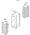
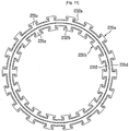
- FIG. 11 illustrates a third embodiment of the stator 30, especially a core and an insulator.
- the stator 30 includes an outer core 231a having a plurality of teeth 231 extending outwardly in a radial direction and a base 131d connecting each inner end of the teeth 231c as one body; and an inner core 231b having a plurality of teeth 231e extending inwardly in a radius direction and a base 231f connecting each outer end of the teeth 231e.
- an insulator includes a first insulator 232a surrounding the outer core 231a and a second insulator 232b surrounding the inner core 231b.
- the first and second insulator 232a and 232b may be formed separately, but preferably is formed as one body. Even in case that the first and second insulator 232a and 232b are formed as one body, preferably a partition wall is provided between the first and second insulator 232a and 232b so as to partition the outer core 231a and the inner core 231b.
- the first and second insulator 22a and 232b include each upper and lower insulator to be fastened as one body, as similarly as the insulator of the embodiment described before.
- each core 231a and 231b may be a can type core layered with a plurality of metal plates having appearances of the teeth 231c and 231e, and the base 231d and 231f.
- the outer core 231a and the inner core 231b may be made as a spiral core layered with metal plates, with rotating them in a spiral shape, having appearances of the teeth 231c and 231e and the base 231d and 231f.
- the outer and inner core 231a and 231b allow a plurality of multi-partition cores layered with a plurality of metal plates formed, and connects those multi-partition cores one another in a circular shape.
- the metal plates have appearances of the plurality of the teeth 231c and 231e and the base 231d and 231f.
- Each stator of the dual rotor type motor described in the above embodiments has the molding part for supporting the core and the insulator at the same time.
- the insulator may support the core.
- FIGS. 12 through 14 illustrate a second embodiment of that stator.
- the structure of an outer rotor 10 and an inner rotor 20 according to the second embodiment of the dual type motor is the same as the structure of the dual rotor type motor according to the first embodiment of the present invention. Thereby, it will be omitted.
- the stator 330 of the dual rotor type motor according to the second embodiment of the present invention includes a plurality of single-partition cores 331 as discrete components, an insulator 332 of insulating resin for surrounding the single-partition cores 331, and a coil 334 wound around an outer surface of the insulator 332.
- the single-partition core 331 is formed in an approximate I-shape, but may be a T-shape or each pair thereof may face each other.
- the insulator 332 includes a lower insulator 332a and an upper insulator 332b fastened to an upper of the lower insulator 332a.
- the lower and upper insulator 332a and 332b include a core holder 332c for respectively holding the single-partition cores 331, a connector 332d for connecting inner ends of the core holder 332c as well as forming the insulator of a circular shape.
- the connecting part may connect outer ends of the core holder 332c to connect it as one unit.
- the core holder 332c of the lower and upper insulator 332a and 332b has an inner and outer end thereof opened, and both ends of the single-partition core 331 has a shoe 331a thereof exposed outside.
- the exposed shoes 331a of each single-partition core 331 are facing the magnets 12 and 22 of the outer rotor 10 and inner rotor 20.
- a fixing part 335 of an annular shape having an L-shape section is formed as one body on an inner circumferential surface of the upper insulator 332c.
- the fixing part 335 is injection-molded as one body when injection-molding the insulator 332, and alternatively, it may be fastened to the insulator by fastening means such as screws or by bonding.
- a strength reinforcement rib 335c is formed on an inner or an outer surface of the fixing part 335, or both of the inner and outer surfaces thereof for reinforcing the strength of the fixed part.
- the second embodiment of the present invention suggests that strength reinforcement ribs 335c are formed on the outer surface of the fixing part 335. In case that they are formed on the inner surfaces of the fixing part 335, the strength reinforcement ribs should not interfere with the rotation of the inner rotor 20.
- a strength reinforcement bracket (not shown) may be tightly fastened to the inner or outer surface of the fixing part 335 for reinforcing the strength of the fixing part 335.
- a plurality of fastening holes 35a each corresponding to the bolt fastening hole 2c of the bearing housing 2a is formed in a predetermined distance.
- a portion around each fastening hole 35a of the fixing part 35, more specifically the portion where a head of the bolt 39 is contacted, is slightly projected from the other portions.
- the stator 330 is secured to the shaft 4 with a precise concentricity.
- a plurality of position-determining protrusions 2d is projected at a first side of the bolt fastening hole 2c in a predetermined distance, and preferably a position-determining recess 335b is formed to have each position-determining protrusion inserted thereto precisely.
- the position-determining recess 335b may be formed as a through hole passing through the fixing part 335.
- a position-determining recess is formed at the bearing housing 2a, and a position-determining protrusion s formed at the fixing part 335.
- a connector 337 for supplying power to each coil 334 of the stator 330, and a hall sensor 338 for detecting the position of the magnets 22 of the inner rotor 20 are fastened to the insulator 332.
- the hall sensor 338 is provided for detecting the position of the magnets 22 of the inner rotor 20, but alternatively a hall sensor may be provided for detecting the position of the magnets 12 of the outer rotor 10.
- the coil 334 wound around each core holding part 332c of the insulator 332 is preferably an enameled copper wire.
- the stator 330 of the motor with the above configurations will be assembled as follows.
- each coil 334 is wound around each core holding part 332c of the insulator 332 by means of the winding machine.
- a worker inserts the position-determining recess 335b of the fixing part 335 to the position-determining protrusion 2d of the bearing housing 2a for securing the position of the insulator 332 to the bearing housing 2a precisely. Also, he/ she fastens each bolt 339 through each fastening hole 335a of the fixing part 335 and each bolt fastening hole 2c of the bearing housing 2a.
- cores connecting a plurality of cores one another may be used as core of the stator, not the single-partition core.
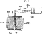
- a core of the stator includes an outer core 431a having a plurality of teeth 431c extending outwardly in a radius direction and a base 431d for connecting inner ends of the teeth one another as one body; and an inner core 431b having a plurality of teeth 431e extending inwardly in a radius direction and a base 431f for connecting outer ends of the teeth 431e one another as one body.
- An insulator 432 includes an upper insulator surrounding the outer core 431a and an upper of the inner core 431b, and a lower insulator 432a surrounding the outer core 431a and a lower of the inner core431b.
- a partition wall 432c is formed between an inside and outside of the lower and upper insulator 432a and 432b as one body for separating the outer core 431a from the inner core 431b.
- the lower and upper insulator 432a and 432b may be fastened in a well-known method of a hook fastening method.
- the lower and upper insulator may be formed as one body by means of insert injection-molding for surrounding the outer core 431a and the inner core 431b.
- a fixing part 435 is formed in the middle of the upper insulator 432b for securing the lower and upper insulator 432a and 432b to the bearing housing 2a.
- the fixing part 435 has an L-shaped section as similar as the embodiment described before, and extends inwardly in a radius direction.
- a plurality of fastening holes 435a corresponding with the bolt fastening holes 2b (see FIG. 12 ) of the bearing housing 2a (see FIG. 12 ) is formed at an inner end of the fixing part 435, with passing through the fixing part.
- a plurality of strength reinforcement ribs 435c is formed at an outer surface of the fixing part 435 for reinforcing the strength of the fixing part.
- each core 431a and 431b may be formed as a tube type core layered with a plurality of metal plates having shapes of the teeth 431c and 431e and the base 431d and 431f.
- the outer core 431a and the inner core 431b may be each formed as a spiral core spirally layered with metal plates each having the shape of the teeth 431c and 431e and the base 431d and 431f.
- the outer core 431a and the inner core 431b may be formed as a plurality of multi-partition cores layered with a plurality of metal plates to connect the multi-partition cores one another in a circular shape.
- each of the metal plates may have a plurality of teeth 431c and 431e and a base of a circular arc shape 431d and 431f.
- a reference number 434 with no description is a coil wound around the insulator 432.
- the fixing parts 335 and 435 of the insulators 332 and 432 are extending inwardly in a radius direction from a first end of the insulator, but alternatively may be extending outwardly in a radius direction.
- the stator 30 of the motor is described to be secured to the hearing housing 2a of the washing machine, but alternatively may be secured to the rear surface of the tub 2 (see FIG. 1 ) and also may be secured to other portions concentrically with the shaft 4.
- the output of the motor may be enhanced without enlarging the size and weight of the motor, because the inner rotor and the outer rotor are provided in the inner portion and outer portion of the stator according to the present invention.
- stator it is easy to secure to an appliance such as a washing machine, because the core of the stator and the insulator are supported by the molding part.
- the molding part is surrounding the core of the stator, the insulator and the coil, water-proof efficiency of the stator may be enhanced.
- water-proof efficiency of the stator may be enhanced.
- air for cooling is ventilated smoothly to radiate the heat of the motor more efficiently even in rotating/ reverse-rotating the shaft of the motor by agitating.
- the inner space of the inner rotor may be cooled efficiently, because air can flow into the inner and outer side of the inner rotor through the intervals on the portion having the outer rotor and the inner rotor fastened thereto by the embossing of the base of the outer rotor.
- the dual rotor type motor according to the present invention may be applied to a drum type washing machine for great efficiency, and also may be applied to other appliances such as an air conditioner in the same method or similar ones.
Landscapes
- Engineering & Computer Science (AREA)
- Power Engineering (AREA)
- Textile Engineering (AREA)
- Iron Core Of Rotating Electric Machines (AREA)
Claims (14)
- Moteur de type à double rotor, comprenant :un arbre (4) rotatif logé dans un carter de palier (2a) d'une machine ;un ensemble de rotor rotatif et dont le centre est fixé à l'arbre, ledit ensemble de rotor comprenant un rotor extérieur (10) espacé d'une distance définie du centre de l'arbre et pourvu d'aimants fixés le long d'une direction circonférentielle, et un rotor intérieur (20) prévu à une distance définie à l'intérieur du rotor extérieur (10), avec des aimants fixés le long d'une direction circonférentielle ; etun stator (30) comprenant un noyau en métal, un isolant (32) en matériau isolant destiné à entourer le noyau (31) de sorte qu'une première surface et une deuxième surface du noyau (31) sont exposées vers l'extérieur, une bobine (34) enroulée sur la surface extérieure de l'isolant (32), une pièce moulée (33) en matériau isolant destinée à entourer l'isolant (32) et la bobine (34) par moulage par insertion en tant que corps monobloc de sorte que la première et la deuxième surfaces du noyau (31) sont exposées dans un état de l'isolant (32), et prévue avec une forme circulaire, et une pièce de fixation (35) pour fixer la pièce moulée (33) au carter de palier, le stator (30) étant monté entre le rotor extérieur (10) et le rotor intérieur (20) de sorte que la première et la deuxième surfaces exposées du noyau (31) font face à une distance définie aux aimants du rotor extérieur et du rotor intérieur (10, 20), respectivement,caractérisé en ce que le noyau (31) comprend :un noyau extérieur (231a) comprenant une première pluralité de dents (231c) s'étendant en direction radiale, une première surface de ceux-ci étant opposée aux aimants du rotor extérieur (10), et une première base (231d) pour la connexion entre elles d'extrémités intérieures de la première pluralité de dents (231 c) ; etun noyau intérieur (231b) comprenant une deuxième pluralité de dents (231e) s'étendant en direction radiale, une deuxième surface de ceux-ci étant opposée aux aimants du rotor intérieur (20), et une deuxième base (231f) pour la connexion entre elles d'extrémités extérieures de la deuxième pluralité de dents (23 le).
- Moteur de type à double rotor selon la revendication 1, comprenant en outre une unité de détermination de position destinée à déterminer la position de la pièce moulée (33) sur la base de la position du carter de palier (2a).
- Moteur de type à double rotor selon la revendication 1, comprenant en outre une pièce de renforcement de résistance destinée à renforcer la résistance de la pièce moulée (33), et où la pièce de renforcement de résistance consiste en une pluralité de nervures de renforcement de résistance (33a) formées sur une surface extérieure de la pièce moulée (33) en tant que corps monobloc.
- Moteur de type à double rotor selon la revendication 1, où une pluralité de nervures de renforcement de résistance (33a) est formée sur la pièce de fixation (35) pour renforcer la résistance de la pièce de fixation (35),
et comprenant en outre un support métallique de renforcement de résistance de forme annulaire prévu sur une partie de raccordement de la pièce moulée (33) à la pièce de fixation (35) pour un renforcement de résistance. - Moteur de type à double rotor selon la revendication 1, où
le stator (30) comprend le noyau (31) en métal, l'isolant (32) en matériau isolant destiné à entourer le noyau (31) de sorte qu'une première surface et une deuxième surface du noyau (31) sont exposées vers l'extérieur, la bobine (34) enroulée sur la surface extérieure de l'isolant (32), et une pièce de fixation (35) pour fixer l'isolant (32) au carter de palier, le stator (30) étant monté entre le rotor extérieur (10) et le rotor intérieur (20) de sorte que la première et la deuxième surfaces exposées du noyau (31) font face à une distance définie aux aimants du rotor extérieur et du rotor intérieur (10, 20), respectivement. - Moteur de type à double rotor selon la revendication 1 ou la revendication 5, où le noyau (31) comprend un noyau à cloison unique (31) en tant que composant discret.
- Moteur de type à double rotor selon la revendication 1 ou la revendication 5, où le noyau extérieur (31) et le noyau intérieur (31) se présentent chacun sous forme de noyau stratifié d'une pluralité de plaques métalliques ayant la forme des dents et des bases,
où le noyau extérieur (31) et le noyau intérieur (31) se présentent chacun sous forme de noyau hélicoïdal stratifié en spirale d'une plaque métallique comme un ruban ayant la forme des dents et des bases, ou bien
où le noyau extérieur (31) et le noyau intérieur (31) ont des noyaux à plusieurs cloisons stratifiés d'une pluralité de plaques métalliques pourvues d'une pluralité de dents et d'une base circulaire reliant la pluralité de dents, et où les noyaux à plusieurs cloisons sont reliés avec une forme circulaire. - Moteur de type à double rotor selon la revendication 1 ou la revendication 5, où l'isolant (32) entourant le noyau (31) comprend un premier isolant (32) destiné à entourer le noyau extérieur (231a), un deuxième isolant (32) destiné à entourer le noyau intérieur (231b), et une paroi de cloisonnement prévue entre le premier et le deuxième isolant (32) pour séparer le noyau extérieur (23 la) du noyau intérieur (231b).
- Moteur de type à double rotor selon la revendication 5, où la pièce de fixation (35) est moulée par injection dans l'isolant (32).
- Moteur de type à double rotor selon la revendication 5, comprenant en outre une pluralité de nervures de renforcement de résistance (33a) formées comme corps monobloc avec la pièce de fixation (35), et
un support métallique de renforcement de résistance prévu dans la pièce de fixation (35) pour renforcer la résistance de la pièce de fixation (35). - Moteur de type à double rotor selon la revendication 5, comprenant en outre une unité de détermination de position destinée à déterminer la position de la pièce de fixation (35) sur la base de la position du carter de palier.
- Moteur de type à double rotor selon la revendication 2 ou la revendication 11, où l'unité de détermination de position comprend au moins une saillie de détermination de position se dressant sur le carter de palier, et au moins une cavité de détermination de position (35b) formée sur la pièce de fixation (35) pour recevoir la saillie de détermination de position qui y est engagée,
la saillie de détermination de position comprenant un corps de diamètre régulier, et une section de guidage (13b) formée à une extrémité du corps avec un flanc de forme conique,
la cavité de détermination de position (35b) comprenant une section horizontale de diamètre régulier correspondant au corps de la saillie de détermination de position, et une section inclinée formée en cône à une extrémité de la section horizontale, et
la cavité de détermination de position ayant un diamètre inférieur au trou de fixation de la pièce de fixation (35) fixé par le boulon. - Moteur de type à double rotor selon la revendication 1 ou la revendication 5, comprenant en outre une section à trous de refroidissement (13) comprenant une pluralité de trous de refroidissement (13a) traversant le rotor extérieur (10) pour un passage d'air, et une section de guidage (13b) formée en saillie sur le rebord du trou de refroidissement (13) pour guider l'air dans les deux sens de rotation du rotor.
- Moteur de type à double rotor selon la revendication 1 ou la revendication 5, où la machine recevant le moteur de type à double rotor est une machine à laver.
Applications Claiming Priority (4)
| Application Number | Priority Date | Filing Date | Title |
|---|---|---|---|
| KR1020050004170A KR100640803B1 (ko) | 2005-01-17 | 2005-01-17 | 이중 로터형 모터 |
| KR1020050004169A KR100640802B1 (ko) | 2005-01-17 | 2005-01-17 | 이중 로터형 모터 |
| KR1020050004984A KR100640804B1 (ko) | 2005-01-19 | 2005-01-19 | 모터 |
| PCT/KR2006/000171 WO2006075903A2 (fr) | 2005-01-17 | 2006-01-17 | Moteur du type a double rotor |
Publications (3)
| Publication Number | Publication Date |
|---|---|
| EP1854199A2 EP1854199A2 (fr) | 2007-11-14 |
| EP1854199A4 EP1854199A4 (fr) | 2016-12-07 |
| EP1854199B1 true EP1854199B1 (fr) | 2018-03-28 |
Family
ID=36678019
Family Applications (1)
| Application Number | Title | Priority Date | Filing Date |
|---|---|---|---|
| EP06702890.2A Active EP1854199B1 (fr) | 2005-01-17 | 2006-01-17 | Moteur du type a double rotor |
Country Status (3)
| Country | Link |
|---|---|
| US (1) | US7557486B2 (fr) |
| EP (1) | EP1854199B1 (fr) |
| WO (1) | WO2006075903A2 (fr) |
Families Citing this family (50)
| Publication number | Priority date | Publication date | Assignee | Title |
|---|---|---|---|---|
| EP1516418B1 (fr) * | 2002-06-26 | 2011-03-23 | Amotech Co., Ltd. | Moteur a courant continu sans balai de type a carcasse radiale ayant une structure à double rotors |
| KR100651850B1 (ko) * | 2005-02-01 | 2006-12-01 | 엘지전자 주식회사 | 세탁기 |
| KR100651849B1 (ko) * | 2005-02-01 | 2006-12-01 | 엘지전자 주식회사 | 세탁기 |
| US7348706B2 (en) * | 2005-10-31 | 2008-03-25 | A. O. Smith Corporation | Stator assembly for an electric machine and method of manufacturing the same |
| CN100438278C (zh) * | 2006-09-14 | 2008-11-26 | 湖南大学 | 复合式电机 |
| JP4420245B2 (ja) * | 2007-03-12 | 2010-02-24 | パナソニック株式会社 | モータ |
| KR101273594B1 (ko) * | 2007-04-05 | 2013-06-14 | 삼성전자주식회사 | 모터 및 이를 갖춘 드럼세탁기 |
| US7800276B2 (en) * | 2007-05-17 | 2010-09-21 | Kurz-Kasch, Inc. | Rotor assembly |
| JP5256801B2 (ja) * | 2007-07-05 | 2013-08-07 | パナソニック株式会社 | 電動機 |
| AU2008283118A1 (en) * | 2007-08-01 | 2009-02-05 | Fisher & Paykel Appliances Limited | Improved appliance, rotor and magnet element |
| US7671509B2 (en) * | 2007-08-20 | 2010-03-02 | Scott Terry D | Rotor and stator assemblies for permanent magnet electric generator |
| JP4966164B2 (ja) * | 2007-11-05 | 2012-07-04 | 株式会社東芝 | 洗濯機 |
| JP5556000B2 (ja) * | 2008-10-15 | 2014-07-23 | パナソニック株式会社 | デュアルロータモータ |
| KR101026083B1 (ko) * | 2008-12-23 | 2011-03-31 | 주식회사 아모텍 | 슬림형 스테이터 및 그의 제조방법 |
| JP5398274B2 (ja) * | 2009-01-15 | 2014-01-29 | 株式会社東芝 | 永久磁石回転電機 |
| ES2373773T3 (es) | 2009-03-12 | 2012-02-08 | Whirlpool Corporation | Lavadora con un sistema de motor de accionamiento directo. |
| KR101460133B1 (ko) * | 2009-08-17 | 2014-11-11 | 삼성전자 주식회사 | 세탁기용 모터와 이를 가지는 세탁기 |
| US8405268B2 (en) | 2010-02-18 | 2013-03-26 | Nidec Motor Corporation | Stator with monolithic mounting bosses and assembly comprising the same |
| KR101039635B1 (ko) * | 2010-03-11 | 2011-06-08 | 주식회사 제이엠더블유 | 헤어 드라이어용 비엘디씨 모터 |
| AR083135A1 (es) * | 2011-10-05 | 2013-02-06 | Ind Metalurgicas Pescarmona S A I C Y F | Generador eolico sincronico |
| US9080279B2 (en) | 2011-10-24 | 2015-07-14 | Lg Electronics Inc. | Washing machine to produce three-dimensional motion |
| US9512551B2 (en) | 2011-10-24 | 2016-12-06 | Lg Electronics Inc. | Washing machine to produce three-dimensional motion |
| US8866362B2 (en) | 2011-10-25 | 2014-10-21 | General Electric Company | Lamination stack for an electrical machine stator |
| US8539665B2 (en) | 2011-10-26 | 2013-09-24 | Whirlpool Corporation | Method of manufacturing a rotor for an electric motor for a washing machine |
| KR101368243B1 (ko) * | 2011-11-10 | 2014-02-27 | 주식회사 아모텍 | 세탁기용 모터, 세탁기 모터 제조방법 및 이를 구비한 세탁기 |
| KR20130102665A (ko) * | 2012-03-07 | 2013-09-23 | 삼성전자주식회사 | 모터와 이를 가지는 세탁기 |
| US9425664B2 (en) | 2012-05-09 | 2016-08-23 | Thingap, Llc | Composite stator for electromechanical power conversion |
| US9312730B2 (en) * | 2012-10-11 | 2016-04-12 | Whirlpool Corporation | Stator with a polymeric casing for an electric motor of a washing machine and method of manufacturing the same |
| CA2830944C (fr) * | 2012-10-24 | 2019-10-22 | Mcmaster University | Machine a reluctance commutee a double rotor |
| CN104884699B (zh) * | 2012-12-18 | 2017-02-15 | 阿莫泰克有限公司 | 洗衣机的驱动装置及具有该驱动装置的洗衣机 |
| CN104838054B (zh) * | 2012-12-18 | 2017-06-13 | 阿莫泰克有限公司 | 洗衣机的驱动装置及具有该驱动装置的洗衣机 |
| WO2014112839A1 (fr) * | 2013-01-21 | 2014-07-24 | 주식회사 아모텍 | Dispositif d'entraînement de moteur polyphasé, appareil et procédé d'entraînement de moteur pour machine à laver à l'aide dudit dispositif |
| KR101491050B1 (ko) * | 2013-01-28 | 2015-02-23 | 주식회사 아모텍 | 드럼 세탁기용 구동 모터, 이를 구비한 드럼 세탁기 및 그 구동방법 |
| US9577486B2 (en) * | 2014-04-08 | 2017-02-21 | Remy Technologies, L.L.C. | Conductor retention member for a stator assembly |
| KR101693686B1 (ko) * | 2014-09-23 | 2017-01-09 | 주식회사 아모텍 | 스테이터 및 이를 구비한 모터 |
| CN107210630B (zh) * | 2014-10-31 | 2019-08-16 | 安可赛斯责任有限公司 | 蓄能器以及包括该蓄能器的用户装置 |
| KR102331602B1 (ko) * | 2015-04-06 | 2021-11-30 | 엘지전자 주식회사 | 의류처리장치 |
| EP3165664B1 (fr) * | 2015-11-05 | 2020-07-22 | Electrolux Appliances Aktiebolag | Groupe de lavage pour machines à laver le linge |
| ITUB20160930A1 (it) * | 2016-02-22 | 2017-08-22 | Sit Spa | Struttura di motore elettrico in particolare per ventilatori per aria di combustione, o per miscela aria/gas di combustione, in bruciatori a gas, gruppo statorico per tale struttura di motore elettrico e procedimento di assemblaggio per tale gruppo statorico |
| SE541438C2 (en) * | 2017-07-12 | 2019-10-01 | Scania Cv Ab | A vehicle propulsion system |
| ES2941256T3 (es) | 2018-01-12 | 2023-05-19 | Carrier Corp | Máquina electromagnética sin núcleo con doble rotor |
| EP3518388A1 (fr) * | 2018-01-12 | 2019-07-31 | Carrier Corporation | Intégration d'entraînement de moteur électrique |
| KR102047880B1 (ko) * | 2018-02-01 | 2019-12-04 | 엘지전자 주식회사 | 토크리플 감소를 위한 듀얼 로터 타입 모터 및 이를 포함하는 압축기 |
| US11773525B2 (en) | 2019-05-02 | 2023-10-03 | Whirlpool Corporation | Double-rotor washing type drum washing machine |
| DE102020103397A1 (de) | 2020-02-11 | 2021-08-12 | Dr. Ing. H.C. F. Porsche Aktiengesellschaft | Vorrichtung und Verfahren zum Herstellen eines mit Magneten bestückten Blechpakets eines Rotors einer elektrischen Maschine |
| DE102021003942B4 (de) | 2021-07-29 | 2023-05-11 | DeepDrive GmbH | Stator für eine Radialfluss-Doppelrotormaschine, Radialfluss-Doppelrotormaschine und Verfahren zur Herstellung eines Stators für eine Radialfluss-Doppelrotormaschine |
| DE102022202123B4 (de) | 2022-03-02 | 2023-09-28 | DeepDrive GmbH | Elektrisches Antriebssystem |
| US20230327531A1 (en) * | 2022-04-12 | 2023-10-12 | Hamilton Sundstrand Corporation | Aircraft electric motor |
| DE102022205930B3 (de) | 2022-06-10 | 2023-09-28 | DeepDrive GmbH | Radialfluss-Doppelrotormaschine |
| KR20240041692A (ko) * | 2022-09-23 | 2024-04-01 | 뉴모텍(주) | 세탁기용 모터 |
Family Cites Families (12)
| Publication number | Priority date | Publication date | Assignee | Title |
|---|---|---|---|---|
| US4731554A (en) * | 1985-11-14 | 1988-03-15 | Allied Corporation | Low profile ring-shaped motor |
| US5783894A (en) * | 1995-10-31 | 1998-07-21 | Wither; Thomas A. | Method and apparatus for generating electrical energy |
| US6396190B1 (en) * | 1999-06-07 | 2002-05-28 | Lg Electronics Inc. | Brushless dc motor in washing machine |
| US6460382B1 (en) * | 1999-10-18 | 2002-10-08 | Lg Electronics Inc. | Structure of driving unit in drum type washing machine |
| EP1420099B1 (fr) * | 1999-10-18 | 2012-02-01 | LG Electronics, Inc. | Structure de l'unité d'entraînement dans une machine à laver à tambour |
| EP1516418B1 (fr) * | 2002-06-26 | 2011-03-23 | Amotech Co., Ltd. | Moteur a courant continu sans balai de type a carcasse radiale ayant une structure à double rotors |
| KR100432954B1 (ko) | 2002-06-26 | 2004-05-28 | 주식회사 아모텍 | 레이디얼 코어타입 더블 로터 방식의 비엘디씨 모터 |
| KR20040045732A (ko) | 2002-11-25 | 2004-06-02 | 엘지전자 주식회사 | 세탁기의 모터 냉각구조 |
| ES2307249T3 (es) * | 2002-12-10 | 2008-11-16 | Lg Electronics Inc. | Maquina lavadora del tipo de tambor. |
| KR100545848B1 (ko) | 2003-06-23 | 2006-01-24 | 주식회사 아모텍 | 레이디얼 코어타입 더블 로터 방식의 비엘디씨 모터 및그의 제조방법 |
| JP4457777B2 (ja) * | 2004-06-28 | 2010-04-28 | 日産自動車株式会社 | 回転電機 |
| KR100651873B1 (ko) * | 2005-01-24 | 2006-12-01 | 엘지전자 주식회사 | 모터 |
-
2006
- 2006-01-17 EP EP06702890.2A patent/EP1854199B1/fr active Active
- 2006-01-17 US US10/592,684 patent/US7557486B2/en active Active
- 2006-01-17 WO PCT/KR2006/000171 patent/WO2006075903A2/fr active Application Filing
Non-Patent Citations (1)
| Title |
|---|
| None * |
Also Published As
| Publication number | Publication date |
|---|---|
| EP1854199A2 (fr) | 2007-11-14 |
| WO2006075903A2 (fr) | 2006-07-20 |
| US20070205682A1 (en) | 2007-09-06 |
| US7557486B2 (en) | 2009-07-07 |
| EP1854199A4 (fr) | 2016-12-07 |
| WO2006075903A3 (fr) | 2009-04-30 |
Similar Documents
| Publication | Publication Date | Title |
|---|---|---|
| EP1854199B1 (fr) | Moteur du type a double rotor | |
| US8220295B2 (en) | Driving apparatus for washing machine | |
| EP1842278B1 (fr) | Moteur de type a double rotor | |
| KR100651873B1 (ko) | 모터 | |
| US20050057108A1 (en) | Structure of driving unit in drum type washing machine | |
| KR101707402B1 (ko) | 세탁기용 모터와 이를 갖는 세탁기 | |
| US20090064727A1 (en) | Driving apparatus for washing machine | |
| US20060076845A1 (en) | Rotor of an outer-rotor type motor for use in a washing machine | |
| US7755228B2 (en) | Direct drive motor in washing machine | |
| CN101512878B (zh) | 双转子型马达 | |
| WO2006083108A2 (fr) | Machine a laver avec moteur de type double rotor | |
| KR100640803B1 (ko) | 이중 로터형 모터 | |
| KR20090083153A (ko) | 모터, 이의 제조 방법 및 이를 포함하는 가전 제품 | |
| KR100657660B1 (ko) | 드럼 세탁기용 모터의 로터 구조 | |
| KR100611451B1 (ko) | 드럼 세탁기용 모터의 로터 구조 | |
| KR100651874B1 (ko) | 이중 로터형 모터 | |
| KR20100023697A (ko) | 모터 |
Legal Events
| Date | Code | Title | Description |
|---|---|---|---|
| PUAI | Public reference made under article 153(3) epc to a published international application that has entered the european phase |
Free format text: ORIGINAL CODE: 0009012 |
|
| 17P | Request for examination filed |
Effective date: 20070726 |
|
| AK | Designated contracting states |
Kind code of ref document: A2 Designated state(s): AT BE BG CH CY CZ DE DK EE ES FI FR GB GR HU IE IS IT LI LT LU LV MC NL PL PT RO SE SI SK TR |
|
| AX | Request for extension of the european patent |
Extension state: AL BA HR MK YU |
|
| DAX | Request for extension of the european patent (deleted) | ||
| R17D | Deferred search report published (corrected) |
Effective date: 20090430 |
|
| RIC1 | Information provided on ipc code assigned before grant |
Ipc: D06F 37/30 20060101ALI20090513BHEP Ipc: H02K 16/02 20060101AFI20090513BHEP Ipc: H02K 1/27 20060101ALI20090513BHEP Ipc: H02K 3/32 20060101ALI20090513BHEP Ipc: H02K 1/14 20060101ALI20090513BHEP Ipc: H02K 1/18 20060101ALI20090513BHEP |
|
| A4 | Supplementary search report drawn up and despatched |
Effective date: 20161107 |
|
| RIC1 | Information provided on ipc code assigned before grant |
Ipc: H02K 7/14 20060101ALI20161031BHEP Ipc: D06F 37/30 20060101ALI20161031BHEP Ipc: H02K 1/14 20060101ALI20161031BHEP Ipc: H02K 16/02 20060101AFI20161031BHEP Ipc: H02K 3/32 20060101ALI20161031BHEP Ipc: H02K 1/27 20060101ALI20161031BHEP Ipc: H02K 1/18 20060101ALI20161031BHEP Ipc: H02K 21/12 20060101ALI20161031BHEP |
|
| GRAP | Despatch of communication of intention to grant a patent |
Free format text: ORIGINAL CODE: EPIDOSNIGR1 |
|
| STAA | Information on the status of an ep patent application or granted ep patent |
Free format text: STATUS: GRANT OF PATENT IS INTENDED |
|
| INTG | Intention to grant announced |
Effective date: 20171009 |
|
| RIN1 | Information on inventor provided before grant (corrected) |
Inventor name: JEONG, SEONG HAI Inventor name: KIM, YEONG SOO Inventor name: AHN, IN GEUN Inventor name: CHOI, SOUNG BONG Inventor name: CHO, HUNG MYONG |
|
| GRAJ | Information related to disapproval of communication of intention to grant by the applicant or resumption of examination proceedings by the epo deleted |
Free format text: ORIGINAL CODE: EPIDOSDIGR1 |
|
| STAA | Information on the status of an ep patent application or granted ep patent |
Free format text: STATUS: REQUEST FOR EXAMINATION WAS MADE |
|
| GRAR | Information related to intention to grant a patent recorded |
Free format text: ORIGINAL CODE: EPIDOSNIGR71 |
|
| GRAS | Grant fee paid |
Free format text: ORIGINAL CODE: EPIDOSNIGR3 |
|
| STAA | Information on the status of an ep patent application or granted ep patent |
Free format text: STATUS: GRANT OF PATENT IS INTENDED |
|
| GRAA | (expected) grant |
Free format text: ORIGINAL CODE: 0009210 |
|
| STAA | Information on the status of an ep patent application or granted ep patent |
Free format text: STATUS: THE PATENT HAS BEEN GRANTED |
|
| INTC | Intention to grant announced (deleted) | ||
| RIN1 | Information on inventor provided before grant (corrected) |
Inventor name: KIM, YEONG SOO Inventor name: CHO, HUNG MYONG Inventor name: JEONG, SEONG HAI Inventor name: AHN, IN GEUN Inventor name: CHOI, SOUNG BONG |
|
| AK | Designated contracting states |
Kind code of ref document: B1 Designated state(s): AT BE BG CH CY CZ DE DK EE ES FI FR GB GR HU IE IS IT LI LT LU LV MC NL PL PT RO SE SI SK TR |
|
| INTG | Intention to grant announced |
Effective date: 20180216 |
|
| REG | Reference to a national code |
Ref country code: GB Ref legal event code: FG4D |
|
| REG | Reference to a national code |
Ref country code: CH Ref legal event code: EP |
|
| REG | Reference to a national code |
Ref country code: AT Ref legal event code: REF Ref document number: 984251 Country of ref document: AT Kind code of ref document: T Effective date: 20180415 |
|
| REG | Reference to a national code |
Ref country code: IE Ref legal event code: FG4D |
|
| REG | Reference to a national code |
Ref country code: DE Ref legal event code: R096 Ref document number: 602006055000 Country of ref document: DE |
|
| PG25 | Lapsed in a contracting state [announced via postgrant information from national office to epo] |
Ref country code: FI Free format text: LAPSE BECAUSE OF FAILURE TO SUBMIT A TRANSLATION OF THE DESCRIPTION OR TO PAY THE FEE WITHIN THE PRESCRIBED TIME-LIMIT Effective date: 20180328 Ref country code: LT Free format text: LAPSE BECAUSE OF FAILURE TO SUBMIT A TRANSLATION OF THE DESCRIPTION OR TO PAY THE FEE WITHIN THE PRESCRIBED TIME-LIMIT Effective date: 20180328 |
|
| REG | Reference to a national code |
Ref country code: NL Ref legal event code: MP Effective date: 20180328 |
|
| REG | Reference to a national code |
Ref country code: LT Ref legal event code: MG4D |
|
| PG25 | Lapsed in a contracting state [announced via postgrant information from national office to epo] |
Ref country code: GR Free format text: LAPSE BECAUSE OF FAILURE TO SUBMIT A TRANSLATION OF THE DESCRIPTION OR TO PAY THE FEE WITHIN THE PRESCRIBED TIME-LIMIT Effective date: 20180629 Ref country code: BG Free format text: LAPSE BECAUSE OF FAILURE TO SUBMIT A TRANSLATION OF THE DESCRIPTION OR TO PAY THE FEE WITHIN THE PRESCRIBED TIME-LIMIT Effective date: 20180628 Ref country code: SE Free format text: LAPSE BECAUSE OF FAILURE TO SUBMIT A TRANSLATION OF THE DESCRIPTION OR TO PAY THE FEE WITHIN THE PRESCRIBED TIME-LIMIT Effective date: 20180328 Ref country code: LV Free format text: LAPSE BECAUSE OF FAILURE TO SUBMIT A TRANSLATION OF THE DESCRIPTION OR TO PAY THE FEE WITHIN THE PRESCRIBED TIME-LIMIT Effective date: 20180328 |
|
| PG25 | Lapsed in a contracting state [announced via postgrant information from national office to epo] |
Ref country code: PL Free format text: LAPSE BECAUSE OF FAILURE TO SUBMIT A TRANSLATION OF THE DESCRIPTION OR TO PAY THE FEE WITHIN THE PRESCRIBED TIME-LIMIT Effective date: 20180328 Ref country code: NL Free format text: LAPSE BECAUSE OF FAILURE TO SUBMIT A TRANSLATION OF THE DESCRIPTION OR TO PAY THE FEE WITHIN THE PRESCRIBED TIME-LIMIT Effective date: 20180328 Ref country code: EE Free format text: LAPSE BECAUSE OF FAILURE TO SUBMIT A TRANSLATION OF THE DESCRIPTION OR TO PAY THE FEE WITHIN THE PRESCRIBED TIME-LIMIT Effective date: 20180328 Ref country code: RO Free format text: LAPSE BECAUSE OF FAILURE TO SUBMIT A TRANSLATION OF THE DESCRIPTION OR TO PAY THE FEE WITHIN THE PRESCRIBED TIME-LIMIT Effective date: 20180328 Ref country code: ES Free format text: LAPSE BECAUSE OF FAILURE TO SUBMIT A TRANSLATION OF THE DESCRIPTION OR TO PAY THE FEE WITHIN THE PRESCRIBED TIME-LIMIT Effective date: 20180328 |
|
| PG25 | Lapsed in a contracting state [announced via postgrant information from national office to epo] |
Ref country code: CZ Free format text: LAPSE BECAUSE OF FAILURE TO SUBMIT A TRANSLATION OF THE DESCRIPTION OR TO PAY THE FEE WITHIN THE PRESCRIBED TIME-LIMIT Effective date: 20180328 Ref country code: SK Free format text: LAPSE BECAUSE OF FAILURE TO SUBMIT A TRANSLATION OF THE DESCRIPTION OR TO PAY THE FEE WITHIN THE PRESCRIBED TIME-LIMIT Effective date: 20180328 |
|
| REG | Reference to a national code |
Ref country code: AT Ref legal event code: MK05 Ref document number: 984251 Country of ref document: AT Kind code of ref document: T Effective date: 20180328 |
|
| PG25 | Lapsed in a contracting state [announced via postgrant information from national office to epo] |
Ref country code: PT Free format text: LAPSE BECAUSE OF FAILURE TO SUBMIT A TRANSLATION OF THE DESCRIPTION OR TO PAY THE FEE WITHIN THE PRESCRIBED TIME-LIMIT Effective date: 20180730 |
|
| REG | Reference to a national code |
Ref country code: DE Ref legal event code: R097 Ref document number: 602006055000 Country of ref document: DE |
|
| PG25 | Lapsed in a contracting state [announced via postgrant information from national office to epo] |
Ref country code: AT Free format text: LAPSE BECAUSE OF FAILURE TO SUBMIT A TRANSLATION OF THE DESCRIPTION OR TO PAY THE FEE WITHIN THE PRESCRIBED TIME-LIMIT Effective date: 20180328 Ref country code: DK Free format text: LAPSE BECAUSE OF FAILURE TO SUBMIT A TRANSLATION OF THE DESCRIPTION OR TO PAY THE FEE WITHIN THE PRESCRIBED TIME-LIMIT Effective date: 20180328 |
|
| PLBE | No opposition filed within time limit |
Free format text: ORIGINAL CODE: 0009261 |
|
| STAA | Information on the status of an ep patent application or granted ep patent |
Free format text: STATUS: NO OPPOSITION FILED WITHIN TIME LIMIT |
|
| PG25 | Lapsed in a contracting state [announced via postgrant information from national office to epo] |
Ref country code: IT Free format text: LAPSE BECAUSE OF FAILURE TO SUBMIT A TRANSLATION OF THE DESCRIPTION OR TO PAY THE FEE WITHIN THE PRESCRIBED TIME-LIMIT Effective date: 20180328 |
|
| 26N | No opposition filed |
Effective date: 20190103 |
|
| PG25 | Lapsed in a contracting state [announced via postgrant information from national office to epo] |
Ref country code: SI Free format text: LAPSE BECAUSE OF FAILURE TO SUBMIT A TRANSLATION OF THE DESCRIPTION OR TO PAY THE FEE WITHIN THE PRESCRIBED TIME-LIMIT Effective date: 20180328 |
|
| PG25 | Lapsed in a contracting state [announced via postgrant information from national office to epo] |
Ref country code: MC Free format text: LAPSE BECAUSE OF FAILURE TO SUBMIT A TRANSLATION OF THE DESCRIPTION OR TO PAY THE FEE WITHIN THE PRESCRIBED TIME-LIMIT Effective date: 20180328 |
|
| REG | Reference to a national code |
Ref country code: CH Ref legal event code: PL |
|
| GBPC | Gb: european patent ceased through non-payment of renewal fee |
Effective date: 20190117 |
|
| PG25 | Lapsed in a contracting state [announced via postgrant information from national office to epo] |
Ref country code: LU Free format text: LAPSE BECAUSE OF NON-PAYMENT OF DUE FEES Effective date: 20190117 |
|
| REG | Reference to a national code |
Ref country code: BE Ref legal event code: MM Effective date: 20190131 |
|
| REG | Reference to a national code |
Ref country code: IE Ref legal event code: MM4A |
|
| PG25 | Lapsed in a contracting state [announced via postgrant information from national office to epo] |
Ref country code: FR Free format text: LAPSE BECAUSE OF NON-PAYMENT OF DUE FEES Effective date: 20190131 |
|
| PG25 | Lapsed in a contracting state [announced via postgrant information from national office to epo] |
Ref country code: BE Free format text: LAPSE BECAUSE OF NON-PAYMENT OF DUE FEES Effective date: 20190131 |
|
| PG25 | Lapsed in a contracting state [announced via postgrant information from national office to epo] |
Ref country code: CH Free format text: LAPSE BECAUSE OF NON-PAYMENT OF DUE FEES Effective date: 20190131 Ref country code: LI Free format text: LAPSE BECAUSE OF NON-PAYMENT OF DUE FEES Effective date: 20190131 Ref country code: GB Free format text: LAPSE BECAUSE OF NON-PAYMENT OF DUE FEES Effective date: 20190117 |
|
| PG25 | Lapsed in a contracting state [announced via postgrant information from national office to epo] |
Ref country code: IE Free format text: LAPSE BECAUSE OF NON-PAYMENT OF DUE FEES Effective date: 20190117 |
|
| PG25 | Lapsed in a contracting state [announced via postgrant information from national office to epo] |
Ref country code: TR Free format text: LAPSE BECAUSE OF FAILURE TO SUBMIT A TRANSLATION OF THE DESCRIPTION OR TO PAY THE FEE WITHIN THE PRESCRIBED TIME-LIMIT Effective date: 20180328 |
|
| PG25 | Lapsed in a contracting state [announced via postgrant information from national office to epo] |
Ref country code: CY Free format text: LAPSE BECAUSE OF FAILURE TO SUBMIT A TRANSLATION OF THE DESCRIPTION OR TO PAY THE FEE WITHIN THE PRESCRIBED TIME-LIMIT Effective date: 20180328 |
|
| PG25 | Lapsed in a contracting state [announced via postgrant information from national office to epo] |
Ref country code: IS Free format text: LAPSE BECAUSE OF FAILURE TO SUBMIT A TRANSLATION OF THE DESCRIPTION OR TO PAY THE FEE WITHIN THE PRESCRIBED TIME-LIMIT Effective date: 20180728 |
|
| PG25 | Lapsed in a contracting state [announced via postgrant information from national office to epo] |
Ref country code: HU Free format text: LAPSE BECAUSE OF FAILURE TO SUBMIT A TRANSLATION OF THE DESCRIPTION OR TO PAY THE FEE WITHIN THE PRESCRIBED TIME-LIMIT; INVALID AB INITIO Effective date: 20060117 |
|
| PGFP | Annual fee paid to national office [announced via postgrant information from national office to epo] |
Ref country code: DE Payment date: 20221205 Year of fee payment: 18 |