EP1854168B1 - Folienantenne für ein fahrzeug - Google Patents
Folienantenne für ein fahrzeug Download PDFInfo
- Publication number
- EP1854168B1 EP1854168B1 EP06706322A EP06706322A EP1854168B1 EP 1854168 B1 EP1854168 B1 EP 1854168B1 EP 06706322 A EP06706322 A EP 06706322A EP 06706322 A EP06706322 A EP 06706322A EP 1854168 B1 EP1854168 B1 EP 1854168B1
- Authority
- EP
- European Patent Office
- Prior art keywords
- contact
- film
- electronic device
- antenna
- antenna arrangement
- Prior art date
- Legal status (The legal status is an assumption and is not a legal conclusion. Google has not performed a legal analysis and makes no representation as to the accuracy of the status listed.)
- Expired - Lifetime
Links
Images


Classifications
-
- H—ELECTRICITY
- H01—ELECTRIC ELEMENTS
- H01Q—ANTENNAS, i.e. RADIO AERIALS
- H01Q1/00—Details of, or arrangements associated with, antennas
- H01Q1/27—Adaptation for use in or on movable bodies
- H01Q1/32—Adaptation for use in or on road or rail vehicles
- H01Q1/325—Adaptation for use in or on road or rail vehicles characterised by the location of the antenna on the vehicle
-
- H—ELECTRICITY
- H01—ELECTRIC ELEMENTS
- H01Q—ANTENNAS, i.e. RADIO AERIALS
- H01Q1/00—Details of, or arrangements associated with, antennas
- H01Q1/12—Supports; Mounting means
- H01Q1/1271—Supports; Mounting means for mounting on windscreens
-
- H—ELECTRICITY
- H01—ELECTRIC ELEMENTS
- H01Q—ANTENNAS, i.e. RADIO AERIALS
- H01Q1/00—Details of, or arrangements associated with, antennas
- H01Q1/36—Structural form of radiating elements, e.g. cone, spiral, umbrella; Particular materials used therewith
- H01Q1/38—Structural form of radiating elements, e.g. cone, spiral, umbrella; Particular materials used therewith formed by a conductive layer on an insulating support
-
- H—ELECTRICITY
- H01—ELECTRIC ELEMENTS
- H01R—ELECTRICALLY-CONDUCTIVE CONNECTIONS; STRUCTURAL ASSOCIATIONS OF A PLURALITY OF MUTUALLY-INSULATED ELECTRICAL CONNECTING ELEMENTS; COUPLING DEVICES; CURRENT COLLECTORS
- H01R12/00—Structural associations of a plurality of mutually-insulated electrical connecting elements, specially adapted for printed circuits, e.g. printed circuit boards [PCB], flat or ribbon cables, or like generally planar structures, e.g. terminal strips, terminal blocks; Coupling devices specially adapted for printed circuits, flat or ribbon cables, or like generally planar structures; Terminals specially adapted for contact with, or insertion into, printed circuits, flat or ribbon cables, or like generally planar structures
- H01R12/50—Fixed connections
- H01R12/59—Fixed connections for flexible printed circuits, flat or ribbon cables or like structures
- H01R12/65—Fixed connections for flexible printed circuits, flat or ribbon cables or like structures characterised by the terminal
- H01R12/67—Fixed connections for flexible printed circuits, flat or ribbon cables or like structures characterised by the terminal insulation penetrating terminals
- H01R12/68—Fixed connections for flexible printed circuits, flat or ribbon cables or like structures characterised by the terminal insulation penetrating terminals comprising deformable portions
-
- H—ELECTRICITY
- H01—ELECTRIC ELEMENTS
- H01R—ELECTRICALLY-CONDUCTIVE CONNECTIONS; STRUCTURAL ASSOCIATIONS OF A PLURALITY OF MUTUALLY-INSULATED ELECTRICAL CONNECTING ELEMENTS; COUPLING DEVICES; CURRENT COLLECTORS
- H01R2201/00—Connectors or connections adapted for particular applications
- H01R2201/02—Connectors or connections adapted for particular applications for antennas
-
- H—ELECTRICITY
- H05—ELECTRIC TECHNIQUES NOT OTHERWISE PROVIDED FOR
- H05K—PRINTED CIRCUITS; CASINGS OR CONSTRUCTIONAL DETAILS OF ELECTRIC APPARATUS; MANUFACTURE OF ASSEMBLAGES OF ELECTRICAL COMPONENTS
- H05K1/00—Printed circuits
- H05K1/02—Details
- H05K1/11—Printed elements for providing electric connections to or between printed circuits
- H05K1/118—Printed elements for providing electric connections to or between printed circuits specially for flexible printed circuits, e.g. using folded portions
-
- H—ELECTRICITY
- H05—ELECTRIC TECHNIQUES NOT OTHERWISE PROVIDED FOR
- H05K—PRINTED CIRCUITS; CASINGS OR CONSTRUCTIONAL DETAILS OF ELECTRIC APPARATUS; MANUFACTURE OF ASSEMBLAGES OF ELECTRICAL COMPONENTS
- H05K3/00—Apparatus or processes for manufacturing printed circuits
- H05K3/30—Assembling printed circuits with electric components, e.g. with resistors
- H05K3/32—Assembling printed circuits with electric components, e.g. with resistors electrically connecting electric components or wires to printed circuits
- H05K3/325—Assembling printed circuits with electric components, e.g. with resistors electrically connecting electric components or wires to printed circuits by abutting or pinching; Mechanical auxiliary parts therefor
- H05K3/326—Assembling printed circuits with electric components, e.g. with resistors electrically connecting electric components or wires to printed circuits by abutting or pinching; Mechanical auxiliary parts therefor the printed circuit having integral resilient or deformable parts, e.g. tabs or parts of flexible circuits
-
- H—ELECTRICITY
- H05—ELECTRIC TECHNIQUES NOT OTHERWISE PROVIDED FOR
- H05K—PRINTED CIRCUITS; CASINGS OR CONSTRUCTIONAL DETAILS OF ELECTRIC APPARATUS; MANUFACTURE OF ASSEMBLAGES OF ELECTRICAL COMPONENTS
- H05K3/00—Apparatus or processes for manufacturing printed circuits
- H05K3/36—Assembling printed circuits with other printed circuits
- H05K3/361—Assembling flexible printed circuits with other printed circuits
Definitions
- the invention relates to an antenna arrangement for a vehicle having at least one conductive antenna structure according to the features of the preamble of claim 1.
- An antenna arrangement for a vehicle which has at least one conductive antenna structure, wherein this conductive antenna structure is arranged in the form of an electrical conductor in or on a planar component of the vehicle.
- the flat component of the vehicle is a window, in particular the rear window.
- the antenna structures are electrically contacted with an antenna amplifier, wherein the antenna amplifier has a printed circuit board with conductor tracks, on which the corresponding components are arranged and contacted with the conductor tracks in order to realize the function of the antenna amplifier.
- the circuit board itself is inserted into a plastic frame, after the plastic frame has been fixed in turn on the rear window by a gluing process.
- the antenna structures are guided to specific contact points, which also have to be arranged on the rear window.
- an electrical connection between the contact points of the antenna structure and the corresponding contact points on the printed circuit board takes place by means of intermediate contact springs.
- Such a known antenna arrangement has indeed proven itself many times in practice is but in terms of flexibility (eg, if antenna structures change) and due to the high assembly costs unsatisfactory.
- the contacting between the contact point of the antenna structure and the corresponding contact point on the circuit board is possible.
- the invention is therefore based on the object to provide an antenna assembly for a vehicle with a downstream electronic device, which is improved in terms of flexibility and the contact reliability and beyond the assembly cost is reduced.
- the at least one antenna structure is arranged in or on a foil, wherein the foil has a contact area via which the at least one antenna structure is connected electronically directly or via at least one contact partner to the electronic device and the foil is attached to the planar component is arranged.
- the assembly of the film in or on the flat component can be done for example by means of clips or gluing. Clamping or fixing the foil by means of a holding frame is also possible.
- the insertion between two layers of a plastic part is a particularly elegant solution. The structures of the antenna are then particularly well protected and the film is fixed at the same time.
- the film After the film has been arranged on the flat component, it also takes place arrangement of the electronic device adjacent to the film, which in turn has at the end of the respective antenna structures a contact region at which converge the ends of the antenna structures for the purpose of contacting.
- This contact area is either connected directly to the electronic device, or there are intermediate circuits of electrical conductors possible.
- the interposition of electrical conductors comes into consideration when the film is arranged with the antenna structures away from the place where the electronic device is located. However, if the contact region of the film and electronic device are arranged adjacent to one another, it makes sense to electrically connect the contact region, ie the end region of the electrically conductive antenna structures, directly to corresponding contact partners or contact points of the electronic device.
- a direct connection is thus to be understood as meaning processes (detachable or non-detachable connection processes) in which the ends of the antenna structures are directly electrically connected to the corresponding contact points on the printed circuit board of the electronic device.
- it can be thought to make a kind of indirect electrical connection including, for example, in the contact area of the film, a plug connection is provided, which is inserted into a corresponding connector on the electronic device.
- a connector with contact partners is present, wherein the number of contact partners of this connector corresponds to the number of antenna structures. It is also conceivable to lead several antenna structures to a plurality of connectors, so that different connectors are realized for different antenna structures. The at least one connector or a plurality of connectors can then be contacted with corresponding connectors on the electronic device or in the event that the electronic device is not adjacent to the film with the antenna structures, via intermediate electrical conductors (ie a kind of extension cable) electrically get connected.
- intermediate electrical conductors ie a kind of extension cable
- printed conductors and components contacted with these printed conductors for implementing the function of the electronic device are likewise arranged in addition to the antenna structures on the film.
- This has the particular advantage that both the conductor tracks of the electronic device and the antenna structures are arranged on or in the film.
- Particularly advantageous is the arrangement of the electrically conductive regions on the film, so that these, for example, in a screen printing process on the Foil can be printed.
- a further contact between the antenna structures and the electronic device can be dispensed with, which means that the at least one antenna structure is connected directly to the electronic device.
- the at least one antenna structure is connected directly to the electronic device.
- FIG. 1 shows an example Atennenan Aunt 1, in which a plurality of antenna structures 3, 4, 5 are present on a film 2.
- These antenna structures 3 to 5 are applied, for example, in a screen printing process or by any other suitable method on the film 2, wherein the geometric shape and extent of the antenna structures 3 to 5 on the film 2 are directed to the frequencies to be received or transmitted.
- the illustrated antenna structures 3 to 5 are exemplary and are tuned to the respective applications. Use cases are, for example, the reception of radio signals (AM, FM, DAB or the like), television signals (TV, DVB-T or the like) or other signals (eg for central locking of vehicles or the like).
- the film 2 corresponds with their dimensions at most the dimensions of the flat component of the vehicle on which it is arranged.
- the film 2 does not have to be designed plane-parallel, but may also have the contours of the component.
- an attachment of the film 2 for example, below the trunk lid, which consist of an electrically non-conductive material, conceivable, as well as the attachment of the film 2 on vehicle windows (then the film must be 2 transparent) or other components of the vehicle, such as bumpers , Sunroofs, headliners or the like.
- the ends of the electrically conductive antenna structures 3 to 5 are brought together in a contact region 6 of the film 2, so that a contacting of the antenna structures 3 to 5 takes place centrally via this contact region 6 can.
- This contact region 6 is dependent on the outer contours of the film 2, but can also be designed flush with the outer dimensions of the film 2. It is also not necessarily required that the contact region 6 is arranged on an outer edge of the film 2, but may also be present within the film 2.
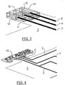
- FIG. 2 shows as an example in an enlarged view the contact region 6 of the film 2, where the ends of the antenna structures 3 to 5 are summarized.
- several contact partners 7, 8, 9 are indicated by way of example, wherein in the case of several antenna structures 3 to 5, in each case identical contact partners are used.
- the first contact partner 7 is a plug or a socket, wherein this contact partner is arranged by means of a crimping operation on the antenna structure 3 and contacted with this electrically.
- the illustrated crimping furthermore has the advantage that, on the one hand, the contact partner 7 is fixed in position on the film 2 and, at the same time, the electrical contacting takes place with the antenna structure 3, which may also have an electrically insulating covering layer, which is pierced by the crimping process.
- the second contact partner 8 is contacted by means of an adhesive bond to the antenna structure 4, for which purpose it must be exposed if it should have an electrically insulating cover layer.
- the further contact partner 9 is a riveted connection, wherein the two contact partners 8, 9 are permanently connected to their associated antenna structures 4, 5.
- the contact partners 8, 9 are connected to an electrical conductor 10, in particular by means of a crimping process.
- the outgoing electrical conductor 10 are, for example, round conductors (strands), but they can also be designed as a ribbon cable. On the side facing away from the contact partners 8, 9 of the electrical conductors 10, for example, these are provided with a plug connection, which can be connected to the electronic device (not shown here). Alternatively, the electrical conductors 10 but also inextricably, for example by means of a soldering process, be connected to the electronic device.
- FIG. 3 is shown as an example that in the contact region 6 of the film 2, a connector 11 is attached, which receives a plurality of contact partners 12, each with the Antenna structures 3 to 5 in a suitable manner (eg in insulation displacement technology, equipment or other way) are connected.
- a connector 11 has the advantage that it centrally receives all contact partners 12 and protects them by an electrically insulating housing from damage, short circuits or the like.
- the handling of such a connector 11 is much easier than if individual contact partners are present.
- FIG. 4 shows as an example the film 2 with the antenna structures arranged thereon 3 to 5, which are bundled in the contact area 6 and connected for example via individual connectors with the corresponding contact points (contact partners) of a downstream electronic device 13.
- This electronic device 13 is, for example, an antenna amplifier, an impedance converter, a booster, a diversity processor or the like. While in FIG. 4 each one connector for each antenna structure 3 to 5 is shown, it is also conceivable that in FIG. 3 shown plug connector 11 with a corresponding mating connector to the electronic device 13.
- FIG. 4 is shown as an example that the electronic device 13 is arranged adjacent to the contact region 6 of the film 2. While a plug connection between the film 2 and the electronic device 13 is shown, it is also conceivable to connect the ends of the antenna structures 3 to 5 in the contact region 6 directly with corresponding contact points of the electronic device 13, in particular by means of an electrically conductive adhesive or a soldering process , In the event that the film 2 and the electronic device 13 are not adjacent to each other, it is conceivable in the contact area 6 and in the region of the electronic device 13 each provide a connector, and between these two connectors an electrical cable (a kind of extension cable ) to switch between end with arranged corresponding connectors.
- an electrical cable a kind of extension cable
- FIG. 5 an embodiment of the invention is shown that the contact region 6 with the ends of the antenna structures 3 to 5 is not located on the edge, but disposed within the film 2 is.
- the contact region 6 can be punched out and connected to the respectively suitable contact partner.
- the electronic device 13 which in turn has a printed circuit board with components arranged thereon, is attached to the film 2 via fastening means (eg, rivets).
- fastening means eg, rivets
- the electronic device 13 has a printed circuit board with electronic components and the antenna structures are connected via contact partners or connectors to the electronic device 13, it is conceivable in another embodiment of the invention that tracks and contacted with these tracks (electronic) components to realize the function of the electronic device 13 are arranged on the film 2.
- tracks and contacted with these tracks (electronic) components to realize the function of the electronic device 13 are arranged on the film 2.
- the tracks on the film 2 for the electronic device 13 are equipped with the components (eg SMD components), so that only only a plug connection for the power supply of the film 2 arranged on the electronic device 13 and an output-side connector for dispensing or Infeed of signals from or into the electronic device 13 must be provided.
- Such a film 2 with integrated electronic device can also completely prefabricated, tested and then delivered to the vehicle manufacturer for installation in the vehicle.
- the films according to the invention are a preferred solution, above all in the edge region of vehicle windows under the black print or on the side. But even a completely pasted vehicle window is conceivable.
- the films can also be self-adhesive. The review is then unproblematic, since there are such film solutions against stone chipping or sunlight (but without conductive structures and without components).
- contact partners for example the contact partners 7 to 9, 12
- at least one of the contact partners is designed as a spring element, which consists of an electrically conductive material and the antenna structure with the other electrical partner (for example, the antenna amplifier or its conductor or pad) electrically connects.
- the spring element has the advantage that it is under bias after contacting (since it has been elastically deformed) and thus maintains the required contact forces throughout its life.
- the Federelemt can be designed so that it comes on the surface of the antenna structure to the plant or possibly also additionally surrounds the film in order to increase the mechanical stability.
Landscapes
- Engineering & Computer Science (AREA)
- Remote Sensing (AREA)
- Details Of Aerials (AREA)
- Support Of Aerials (AREA)
Abstract
Description
- Die Erfindung betrifft eine Antennenanordnung für ein Fahrzeug mit zumindest einer leitfähigen Antennenstruktur gemäß den Merkmalen des Oberbegriffes des Patentanspruches 1.
- Aus der
DE 198 23 202 ist eine Antennenanordnung für ein Fahrzeug bekannt, die zumindest eine leitfähige Antennenstruktur aufweist, wobei diese leitfähige Antennenstruktur in Form eines elektrischen Leiters in oder auf einem flächigen Bauteil des Fahrzeuges angeordnet ist. Bei diesem Stand der Technik ist das flächige Bauteil des Fahrzeuges eine Fensterscheibe, insbesondere die Heckscheibe. Die Antennenstrukturen sind elektrisch mit einem Antennenverstärker kontaktiert, wobei der Antennenverstärker eine Leiterplatte mit Leiterbahnen aufweist, auf der die entsprechenden Bauteile angeordnet und mit den Leiterbahnen kontaktiert sind, um die Funktion des Antennenverstärkers zu realisieren. Die Leiterplatte selber wird in einen Kunststoffrahmen eingesetzt, nachdem der Kunststoffrahmen seinerseits auf der Heckscheibe durch einen Klebevorgang fixiert worden ist. Zur Kontaktierung der Antennenstrukturen mit dem Antennenverstärker sind die Antennenstrukturen zu bestimmten Kontaktstellen geführt, die ebenfalls auf der Heckscheibe angeordnet werden müssen. Beim Einsetzen der Leiterplatte in den Kunststoffrahmen erfolge eine elektrische Verbindung zwischen den Kontaktstellen der Antennenstruktur und den korrespondierenden Kontaktstellen auf der Leiterplatte durch zwischengeschaltete Kontaktfedern. Eine solche bekannte Antennenanordnung hat sich zwar vielfach in der Praxis bewährt, ist aber hinsichtlich der Flexibilität (z.B. wenn sich Antennenstrukturen ändern) sowie auf Grund des hohen Montageaufwandes unbefriedigend. Darüber hinaus ist die Kontaktierung zwischen der Kontaktstelle der Antennenstruktur und der korrespondierenden Kontaktstelle auf der Leiterplatte möglich. Außerdem ist es für den Fall, dass eine Antennenstruktur beschädigt wurde, immer zwangsweise erforderlich, dass die gesamte Scheibe ausgetauscht werden muss, was in nachteiliger Weise mit hohen Kosten verbunden ist. - Der Erfindung liegt daher die Aufgabe zu Grunde, eine Antennenanordnung für ein Fahrzeug mit einem nachgeschalteten elektronischen Gerät bereitzustellen, das hinsichtlich der Flexibilität sowie der Kontaktsicherheit verbessert ist und darüber hinaus der Montageaufwand verringert wird.
- Diese Aufgabe ist durch die Merkmale des Patentanspruches 1 gelöst.
- Erfindungsgemäß ist vorgesehen, dass die zumindest eine Antennenstruktur in oder auf einer Folie angeordnet ist, wobei die Folie einen Kontaktbereich aufweist, über den die zumindest eine Antennenstruktur direkt oder über zumindest einen Kontaktpartner mit dem elektronischen Gerät elektronisch verbunden ist und die Folie an dem flächigen Bauteil angeordnet wird. Die Kombination dieser Merkmale hat mehrere Vorteile. Zum einen ist eine sehr hohe Flexibilität gegeben, da ein aufwändiger Herstellungsprozess eines flächigen Bauteiles des Fahrzeuges mit darin integrierten Antennenstrukturen entfallen kann. Denn in vorteilhafter Weise sind die Antennenstrukturen nunmehr in oder auf der Folie vorhanden und dort beispielsweise als eine elektrisch leitfähige Paste aufgebracht. Die Antennenstrukturen können beispielsweise in einem Siebdruckverfahren in einfachster Weise auf die Folie gedruckt werden. Damit lassen sich Änderungen der Antennenstrukturen sehr schnell und auf einfache Art und Weise realisieren, ohne dass der Herstellungsprozess des flächigen Bauteiles berücksichtigt werden muss. Denn gerade bei Scheiben von Fahrzeugen, die Regelfall aus Verbundmaterial bestehen, sind aufwändige Abstimmungsprozesse erforderlich, wenn innerhalb dieses Verbundes Antennenstrukturen vorhanden sind und diese geändert werden müssen. Außerdem wird der Montageaufwand deutlich verringert, da eine Folie auf die entsprechenden Maße des flächigen Bauteiles zugeschnitten werden kann, und anschließend mit dem flächigen Bauteil durch entsprechende Maßnahmen verbunden wird. Solche Maßnahmen können z.B. Clipsvorgänge, Klebungen oder dergleichen sein.
- Die Montage der Folie in bzw. auf das flächige Bauteil kann zum Beispiel mit Hilfe von Clipsen oder Kleben erfolgen. Klemmen oder Fixieren der Folie mit Hilfe eines Halterahmens ist auch möglich. Das Einlegen zwischen zwei Schichten eines Kunststoffteils stellt eine besonders elegante Lösung dar. Die Strukturen der Antenne sind dann besonders gut geschützt und die Folie ist gleichzeitig fixiert.
- Nachdem die Folie an dem flächigen Bauteil angeordnet worden ist, erfolgt ebenfalls sie Anordnung des elektronischen Gerätes benachbart zu der Folie, die ihrerseits am Ende der jeweiligen Antennenstrukturen einen Kontaktbereich aufweist, an dem die Enden der Antennenstrukturen zusammenlaufen zwecks Kontaktierung. Dieser Kontaktbereich wird entweder direkt mit dem elektronischen Gerät verbunden, oder es sind Zwischenschaltungen von elektrischen Leitern möglich. Die Zwischenschaltung von elektrischen Leitern kommt dann in Betracht, wenn die Folie mit den Antennenstrukturen entfernt von dem Ort angeordnet ist, an dem sich das elektronische Gerät befindet. Sind aber Kontaktbereich der Folie und elektronisches Gerät benachbart zueinander angeordnet, bietet es sich an, den Kontaktbereich, d.h. den Endbereich der elektrisch leitfähigen Antennenstrukturen, direkt mit korrespondierenden Kontaktpartnern bzw. Kontaktstellen des elektronischen Gerätes elektrisch zu verbinden. So kann beispielsweise daran gedacht werden, dass die auf der Folie freiliegenden elektrisch leitfähigen Enden der Antennenstruktur mittels eines elektrisch leitfähigen Klebers mit korrespondierenden Leiterbahnen auf der Leiterplatte des elektronischen Gerätes verbunden werden. Unter einer direkten Verbindung sind also solche Vorgänge (lösbare oder unlösbare Verbindungsvorgänge) zu verstehen, bei denen die Enden der Antennenstrukturen direkt elektrisch mit den korrespondierenden Kontaktstellen auf der Leiterplatte des elektronischen Gerätes verbunden werden. Alternativ dazu kann daran gedacht werden, eine Art indirekte elektrische Verbindung vorzunehmen, wozu z.B. im Kontaktbereich der Folie eine Steckverbindung vorgesehen wird, die in eine korrespondierende Steckverbindung an dem elektronischen Gerät eingesteckt wird. Darüber hinaus ist es weiterhin denkbar, dass im Kontaktbereich der Folie ein Steckverbinder mit Kontaktpartnern vorhanden ist, wobei die Anzahl der Kontaktpartner dieses Steckverbinders der Anzahl der Antennenstrukturen entspricht. Es ist auch denkbar, mehrere Antennenstrukturen zu mehreren Steckverbindern zu führen, so dass für verschiedene Antennenstrukturen auch verschiedene Steckverbinder realisiert sind. Der zumindest eine Steckverbinder oder auch mehrere Steckverbinder können dann mit korrespondierenden Steckverbindern an dem elektronischen Gerät kontaktiert werden oder für den Fall, dass das elektronische Gerät nicht benachbart zu der Folie mit den Antennenstrukturen angeordnet ist, über zwischengeschaltete elektrische Leiter (also eine Art Verlängerungskabel) elektrisch verbunden werden.
- Je nach Anwendungsfall kommen zur Verbindung der Kontaktpartner der Antennenstruktur mit den korrespondierenden Kontaktstellten bzw. Kontaktpartnem des elektronischen Gerätes lösbare Verbindungen wie Schraub- oder Steckverbindungen in Betracht. Diese haben den Vorteil, dass die Folie mit der Antennenstruktur bzw. das elektronische Gerät z.B. im Defektfalle voneinander getrennt und ausgetauscht werden können. Ergänzend oder alternativ dazu kommen unlösbare elektrische Verbindungen wie z.B. Crimp-, Löt-, Klebe-, Niet- oder Bondverbindungen (Bonden = Verbinden durch Klebung und Erwärmung) in Betracht.
- In einer besonderen Ausgestaltung der Erfindung sind Leiterbahnen und mit diesen Leiterbahnen kontaktierte Bauelemente zur Realisierung der Funktion des elektronischen Gerätes ebenfalls in Ergänzung zu den Antennenstrukturen auf der Folie angeordnet. Dies hat den besonderen Vorteil, dass sowohl die Leiterbahnen des elektronischen Gerätes als auch die Antennenstrukturen auf oder in der Folie angeordnet sind. Besonders vorteilhaft ist die Anordnung der elektrisch leitfähigen Bereiche auf der Folie, so dass diese z.B. in einem Siebdruckverfahren auf die Folie aufgedruckt werden können. Insgesamt steht nach Bestückung der Leiterbahnen mit den entsprechenden Bauelementen zur Realisierung der Funktion des elektronischen Gerätes eine vorfertigbare Folie zur Verfügung, die geprüft und nach erfolgreicher Prüfung an den Fahrzeughersteller zum Einbau in das Fahrzeug geliefert werden kann. Es ist lediglich noch eine Stromversorgung und eine ausgangsseitige Kontaktierung des elektronischen Gerätes mit nachgeschalteten Geräten erforderlich. Eine weitere Kontaktierung zwischen den Antennenstrukturen und dem elektronischen Gerät kann damit entfallen, was bedeutet, dass die zumindest eine Antennenstruktur direkt mit dem elektronischen Gerät verbunden ist. Somit werden jegliche Kontaktprobleme zwischen der zumindest einen Antennenstruktur und dem elektronischen Gerät vermieden. Darüber hinaus reduziert sich in vorteilhafter Weise die Bauteilvielfalt, so dass Kosteneinsparungen möglich sind.
- Wenn somit das erfindungsgemäße Gesamtkonzept (Montage sowie Integration) betrachtet wird, sind in vorteilhafter Weise Kosteneinsparungen zu erwarten.
- Da in Fahrzeugen in Zukunft vermehrt Kunststoffteile eingesetzt werden, bieten diese die Möglichkeit mit hoher Designfreiheit dort Antennen bzw. Antennenstrukturen auf der Folie zu integrieren, so dass eine Anpassung an die neuen Möglichkeiten ohne weiteres gegeben ist.
- Verschiedene Beispiele und Ausführungsbeispiele der Erfindung, auf die diese jedoch nicht beschränkt ist, sind im Folgenden beschrieben und anhand der Figuren erläutert.
- Es zeigen:
- Figur 1:
- eine Folie mit Antennenstrukturen,
- Figur 2:
- verschiedene Kontaktpartner, die an der Folie angeordnet sind,
- Figur 3:
- ein Steckverbinder, der an der Folie angeordnet ist,
- Figur 4:
- ein elektronisches Gerät, das an der Folie mit Antennenstrukturen angeordnet ist,
- Figur 5:
- ein elektronisches Gerät, das auf der Folie angeordnet ist
-
Figur 1 zeigt als Beispiel eine Atennenanordnung 1, bei der auf einer Folie 2 mehrere Antennenstrukturen 3, 4, 5 vorhanden sind. Diese Antennenstrukturen 3 bis 5 sind z.B. in einem Siebdruckverfahren oder mittels jedes anderen geeigneten Verfahrens auf der Folie 2 aufgebracht, wobei sich die geometrische Form und Erstreckung der Antennenstrukturen 3 bis 5 auf der Folie 2 nach den zu empfangenden bzw. auszusendenden Frequenzen richten. Die gezeigten Antennenstrukturen 3 bis 5 sind beispielhaft und werden auf die jeweiligen Anwendungsfälle abgestimmt. Anwendungsfälle sind beispielsweise der Empfang von Radiosignalen (AM, FM, DAB oder dergleichen), Fernsehsignalen (TV, DVB-T oder dergleichen) oder sonstiger Signale (z.B. für Zentralverriegelungen von Fahrzeugen oder dergleichen). Die Folie 2 entspricht mit ihren Abmessungen höchstens den Ausmaßen des flächigen Bauteils des Fahrzeuges, an dem sie angeordnet wird. Die Folie 2 muss nicht planparallel ausgestaltet sein, sondern kann auch die Konturen des Bauteils aufweisen. So ist eine Anbringung der Folie 2 z.B. unterhalb von Kofferraumdeckeln, die aus einem elektrisch nicht leitfähigem Material bestehen, denkbar, genauso wie die Anbringung der Folie 2 auf Fahrzeugscheiben (dann muss die Folie 2 durchsichtig sein) oder sonstigen Bauteilen des Fahrzeuges, wie z.B. Stoßfänger, Schiebedächer, Dachhimmel oder dergleichen. - Die Enden der elektrisch leitfähigen Antennenstrukturen 3 bis 5 sind in einen Kontaktbereich 6 der Folie 2 zusammengeführt, so dass zentral über diesen Kontaktbereich 6 eine Kontaktierung der Antennenstrukturen 3 bis 5 erfolgen kann. Dieser Kontaktbereich 6 steht von den äußeren Konturen der Folie 2 ab, kann aber auch bündig mit den Außenabmessungen der Folie 2 gestaltet sein. Es ist auch nicht zwangsweise erforderlich, dass der Kontaktbereich 6 an einem äußeren Rand der Folie 2 angeordnet ist, sondern kann auch innerhalb der Folie 2 vorhanden sein.
-
Figur 2 zeigt als Beispiel in vergrößerter Darstellung den Kontaktbereich 6 der Folie 2, wo die Enden der Antennenstrukturen 3 bis 5 zusammengefasst sind. An diesen Enden der Antennenstrukturen 3 bis 5 sind beispielhaft mehrere Kontaktpartner 7, 8, 9 angedeutet, wobei im Regelfall bei mehreren Antennenstrukturen 3 bis 5 jeweils gleiche Kontaktpartner verwendet werden. Der erste Kontaktpartner 7 ist ein Stecker oder eine Buchse, wobei dieser Kontaktpartner mittels eines Crimpvorganges an der Antennenstruktur 3 angeordnet und mit dieser elektrisch kontaktiert wird. Die dargestellte Vercrimpung hat darüber hinaus den Vorteil, dass einerseits der Kontaktpartner 7 an der Folie 2 lagefixiert wird und gleichzeitig die elektrische Kontaktierung mit der Antennenstruktur 3 erfolgt, wobei diese auch eine elektrisch isolierende Deckschicht aufweisen kann, die von dem Crimpvorgang durchstoßen wird. Der zweite Kontaktpartner 8 wird mittels einer Klebeverbindung an der Antennenstruktur 4 kontaktiert, wozu diese freigelegt werden muss, falls sie eine elektrisch isolierende Deckschicht aufweisen sollte. Der weitere Kontaktpartner 9 ist eine Nietverbindung, wobei die beiden Kontaktpartner 8, 9 unlösbar mit ihre zugehörigen Antennenstrukturen 4, 5 verbunden sind. Abgangsseitig sind die Kontaktpartner 8, 9 mit einem elektrischen Leiter 10, insbesondere mittels eines Crimpvorganges, verbunden. Die abgangsseitigen elektrischen Leiter 10 sind beispielsweise Rundleiter (Litzen), wobei sie aber auch als Flachbandkabel ausgebildet sein können. Auf der den Kontaktpartnern 8, 9 abgewandten Seite der elektrischen Leiter 10 sind diese z.B. mit einer Steckverbindung versehen, die mit dem elektronischen Gerät (hier nicht dargestellt) verbunden werden können. Alternativ dazu können die elektrischen Leiter 10 aber auch unlösbar, z.B. mittels eines Lötvorganges, mit dem elektronischen Gerät verbunden sein. - In
Figur 3 ist als Beispiel dargestellt, dass im Kontaktbereich 6 der Folie 2 ein Steckverbinder 11 befestigt ist, der mehrere Kontaktpartner 12 aufnimmt, die jeweils mit den Antennenstrukturen 3 bis 5 in geeigneter Weise (z.B. in Schneid-Klemmtechnik, Anlagetechnik oder sonstiger Weise) verbunden sind. Ein solcher Steckverbinder 11 hat den Vorteil, dass er zentral alle Kontaktpartner 12 aufnimmt und diese durch ein elektrisch isolierendes Gehäuse vor Beschädigungen, Kurzschlüssen oder dergleichen schützt. Außerdem ist das Handling eines solchen Steckverbinders 11 wesentlich einfacher als wenn einzelne Kontaktpartner vorhanden sind. -
Figur 4 zeigt als Beispiel die Folie 2 mit den darauf angeordneten Antennenstrukturen 3 bis 5, die im Kontaktbereich 6 gebündelt und z.B. über einzelne Steckverbinder mit den korrespondierenden Kontaktstellen (Kontaktpartnern) eines nachgeschalteten elektronischen Gerätes 13 verbunden sind. Bei diesem elektronischen Gerät 13 handelt es sich beispielsweise um einen Antennenverstärker, einen Impedanzwandler, einen Booster, einen Diversity-Prozessor oder dergleichen. Während inFigur 4 jeweils ein Steckverbinder für jeweils eine Antennenstruktur 3 bis 5 dargestellt ist, ist es auch denkbar, den inFigur 3 gezeigten Steckverbinder 11 mit einem entsprechenden Gegensteckverbinder an dem elektronischen Gerät 13 einzustecken. - In
Figur 4 ist als Beispiel dargestellt, dass das elektronische Gerät 13 benachbart zu dem Kontaktbereich 6 der Folie 2 angeordnet ist. Während eine Steckverbindung zwischen der Folie 2 und dem elektronischen Gerät 13 gezeigt ist, ist es auch denkbar, die Enden der Antennenstrukturen 3 bis 5 im Kontaktbereich 6 direkt mit korrespondierenden Kontaktstellen des elektronischen Gerätes 13 zu verbinden, insbesondere mittels eines elektrisch leitfähigen Klebers oder eines Lötvorganges. Für den Fall, dass die Folie 2 und das elektronische Gerät 13 nicht benachbart zueinander angeordnet sind, ist es denkbar, im Kontaktbereich 6 sowie im Bereich des elektronischen Gerätes 13 jeweils eine Steckverbindung vorzusehen, und zwischen diesen beiden Steckverbindungen eine elektrisches Kabel (eine Art Verlängerungskabel) mit endseitig angeordneten korrespondierenden Steckverbindungen zwischen zu schalten. - In
Figur 5 ist ein Ausführungsbeispiel der Erfindung gezeigt, dass der Kontaktbereich 6 mit den Enden der Antennenstrukturen 3 bis 5 nicht am Rand liegt, sondern innerhalb der Folie 2 angeordnet ist. In diesem Fall kann z.B. nach dem Aufdrucken der Antennenstrukturen 3 bis 5 auf die Folie 2 der Kontaktbereich 6 ausgestanzt werden und mit dem jeweils geeigneten Kontaktpartner verbunden werden. Weiterhin ist auch das elektronische Gerät 13, das seinerseits eine Leiterplatte mit darauf angeordneten Bauteilen aufweist, über Befestigungsmittel (z.B. Nieten) an der Folie 2 befestigt ist. Bei dieser Ausgestaltung sind also innerhalb der Außenabmessungen der Folie 2 sowohl die Antennenstrukturen 3 bis 5 als auch das elektronische Gerät 13 vorhanden und damit ein Modul gebildet, das vorgefertigt, geprüft und dann an den Fahrzeughersteller zum Einbau in das Fahrzeug geliefert werden kann. - Während in
Figur 5 gezeigt ist, dass das elektronische Gerät 13 eine Leiterplatte mit elektronischen Bauelementen aufweist und die Antennenstrukturen über Kontaktpartner bzw. Steckverbinder mit dem elektronischen Gerät 13 verbunden sind, ist es in einer weiteren erfindungsgemäßen Ausgestaltung denkbar, dass Leiterbahnen und mit diesen Leiterbahnen kontaktierte (elektronische) Bauelemente zur Realisierung der Funktion des elektronischen Gerätes 13 auf der Folie 2 angeordnet sind. Das bedeutet, dass sowohl die Antennenstrukturen 3 bis 5 als auch die inFigur 5 nicht dargestellten Leiterbahnen, die an und für sich auf der Leiterplatte vorhanden sind, nunmehr allesamt auf die Folie 2 aufgedruckt werden. In diesem Fall entfällt das Ausstanzen des Kontaktbereiches 6 aus der Folie 2. Außerdem entfällt eine elektrische Verbindung (Kontaktierung) der Enden der Antennenstrukturen 3 bis 5 mit den zugehörigen Leiterbahnen des elektronischen Gerätes 13, da diese schon durchgehend auf der Folie 2 vorhanden sind. Dies hat den großen Vorteil, dass damit die gegebenenfalls vorhandenen oder sich einstellenden Kontaktprobleme umgangen werden. Die Leiterbahnen auf der Folie 2 für das elektronische Gerät 13 werden mit den Bauelementen (z.B. SMD-Bauelemente) bestückt, so dass lediglich nur noch eine Steckverbindung für die Stromversorgung des auf der Folie 2 angeordneten elektronischen Gerätes 13 sowie eine ausgangsseitige Steckverbindung zur Abgabe bzw. Einspeisung von Signalen aus bzw. in das elektronische Gerät 13 vorgesehen werden muss. Eine solche Folie 2 mit integriertem elektronischen Gerät kann ebenfalls komplett vorgefertigt, geprüft und dann an den Fahrzeughersteller zum Einbau in das Fahrzeug geliefert werden. - Die erfindungsgemäßen Folien zumindest mit den Antennenstrukturen sind vor allem im Randbereich von Fahrzeugscheiben unter dem Schwarzdruck oder an der Seite eine bevorzugte Lösung. Aber auch eine ganz beklebte Fahrzeugscheibe ist denkbar. Die Folien können auch selbstklebend sein. Die Durchsicht ist dann unproblematisch, da es solche Folienlösungen schon gegen Steinschlag oder Sonneneinstrahlung gibt (allerdings ohne leitende Strukturen und ohne Bauelemente).
- In der vorangegangenen Beschreibung wurde der Kontaktbereich 6, genauer die dort endenden Antennenstrukturen 3 bis 5 fest mit Kontaktpartnern (zum Beispiel die Kontaktpartner 7 bis 9, 12) verbunden. Hier ist es alternativ oder ergänzend auch noch denkbar, dass zumindest einer der Kontaktpartner als Federelement ausgebildet ist, welches aus einem elektrisch leitfähigen Material besteht und die Antennenstruktur mit dem weiteren elektrischen Partner (zum Beispiel dem Antennenverstärker bzw. dessen Leiterbahn oder Kontaktstelle) elektrisch verbindet. Das Federelement hat den Vorteil, dass es nach der Kontaktierung unter Vorspannung steht (da es elastisch verformt wurde) und somit die erforderlichen Kontaktkräfte während seiner gesamten Lebensdauer beibehält. Das Federelemt kann dabei so gestaltet sein, dass es auf der Oberfläche der Antennenstruktur zur Anlage kommte oder gegebenenfalls auch zusätzlich die Folie zwecks Erhöhung der mechanischen Stabilität umgreift.
-
- 1.
- Antennenanordnung
- 2.
- Folie
- 3.
- Antennenstruktur
- 4.
- Antennenstruktur
- 5.
- Antennenstruktur
- 6.
- Kontaktbereich
- 7.
- Kontaktpartner
- 8.
- Kontaktpartner
- 9.
- Kontaktpartner
- 10.
- elektrischer Leiter
- 11.
- Steckverbinder
- 12.
- Kontaktpartner
- 13.
- elektronisches Gerät
Claims (10)
- Antennenanordnung (1) für ein Fahrzeug, wobei die zumindest eine leitfähige Antennenstruktur (3, 4, 5) aufweisende Antennenanordnung (1) In oder auf einem flächigen Bauteil des Fahrzeuges angeordnet ist und elektrisch mit einem elektronischen Gerät (13) kontaktiert ist, wobei die zumindest eine Antennenstruktur (3. 4, 5) In oder auf einer Folie (2) angeordnet ist, wobei die Folie (2) einen Kontaktbereich (6) aufweist, über den die zumindest eine Antennenstruktur (3, 4, 5) direkt oder über zumindest einen Kontaktpartner (7, 8, 9, 12) mit dem elektronischen Gerät (13) elektrisch verbunden ist und die Folie (2) an dem flächigen Bauteil angeordnet wird, dadurch gekennzeichnet, dass der Kontaktbereich (6) mit den Enden der Antennenstrukturen (3 bis 5) innerhalb der Folie (2) angeordnet und ausgestanzt ist und dass das elektronische Gerät (13) über Befestigungsmittel an der Folie (2) befestigt ist
- Antennenanordnung (1) nach Anspruch 1, dadurch gekennzeichnet, dass die zumindest eine leitfähige Antennenstruktur (3, 4, 5) lösbar mit dem zumindest einen Kontaktpartner (7, 8, 9, 12) verbunden ist.
- Antennenanordnung (1) nach Anspruch 2, dadurch gekennzeichnet, dass die lösbare Verbindung eine Schraub- oder Steckverbindung ist.
- Antennenanordnung (1) nach Anspruch 1, dadurch gekennzeichnet, dass die zumindest eine leitfähige Antennenstruktur (3, 4, 5) unlösbar mit dem zumindest einen Kontaktpartner (7, 8, 9, 12) verbunden ist.
- Antennenanordnung (1) nach Anspruch 4, dadurch gekennzeichnet, dass die unlösbare Verbindung eine Crimp-, Löt-, Klebe-, Niet- oder Bondverbindung ist.
- Antennenanordnung (1) nach einem der vorhergehenden Ansprüche, dadurch gekennzeichnet, dass die Kontaktpartner (7, 8, 9, 12) direkt mit korrespondierenden Kontaktpartner des elektronischen Gerätes (13) kontaktierbar sind.
- Antennenanordnung (1) nach einem der vorhergehenden Ansprüche, dadurch gekennzeichnet, dass die Kontaktpartner (7, 8, 9, 12) über zumindest einen elektrischen Leiter (10) mit korrespondierenden Kontaktpartner des elektronischen Gerätes (13) kontaktierbar sind.
- Antennenanordnung (1) nach einem der vorhergehenden Ansprüche, dadurch gekennzeichnet, dass Leiterbahnen und mit diesen Leiterbahnen kontaktierte Bauelemente zur Realisierung der Funktion des elektronischen Gerätes (13) auf der Folie (2) angeordnet sind.
- Antennenanordnung (1) nach einem der vorhergehenden Ansprüche, dadurch gekennzeichnet, dass der elektrische Leiter (10) Bestandteil einer Flachbandleitung ist.
- Antennenanordnung (1) nach einem der vorhergehenden Ansprüche, dadurch gekennzeichnet, dass der zumindest ein Kontaktpartner (7, 8, 9, 12) als Federelement ausgebildet ist.
Applications Claiming Priority (2)
| Application Number | Priority Date | Filing Date | Title |
|---|---|---|---|
| DE200510009443 DE102005009443A1 (de) | 2005-03-02 | 2005-03-02 | Folienantenne für ein Fahrzeug |
| PCT/EP2006/000481 WO2006092188A1 (de) | 2005-03-02 | 2006-01-20 | Folienantenne für ein fahrzeug |
Publications (2)
| Publication Number | Publication Date |
|---|---|
| EP1854168A1 EP1854168A1 (de) | 2007-11-14 |
| EP1854168B1 true EP1854168B1 (de) | 2012-05-16 |
Family
ID=36090953
Family Applications (1)
| Application Number | Title | Priority Date | Filing Date |
|---|---|---|---|
| EP06706322A Expired - Lifetime EP1854168B1 (de) | 2005-03-02 | 2006-01-20 | Folienantenne für ein fahrzeug |
Country Status (3)
| Country | Link |
|---|---|
| EP (1) | EP1854168B1 (de) |
| DE (1) | DE102005009443A1 (de) |
| WO (1) | WO2006092188A1 (de) |
Cited By (1)
| Publication number | Priority date | Publication date | Assignee | Title |
|---|---|---|---|---|
| EP4648219A1 (de) * | 2024-05-08 | 2025-11-12 | Harman International Industries, Incorporated | Integrierte telematikeinheitsantennen für fahrzeuge |
Families Citing this family (15)
| Publication number | Priority date | Publication date | Assignee | Title |
|---|---|---|---|---|
| DE102006053407A1 (de) * | 2006-11-13 | 2008-05-15 | Siemens Ag | Standardisiertes Elektronikgehäuse mit modularen Kontaktpartnern |
| DE102008004320A1 (de) * | 2007-02-02 | 2008-08-14 | Hirschmann Car Communication Gmbh | Antenne, insbesondere für die Datenkommunikation via Satellit |
| EP1995820A1 (de) * | 2007-05-25 | 2008-11-26 | Laird Technologies AB | Verbinder für Antennenvorrichtung, Antennenvorrichtung mit einem derartigen Verbinder und tragbares Funkkommunikationsgerät mit einer derartigen Antennenvorrichtung |
| ATE547824T1 (de) * | 2007-10-16 | 2012-03-15 | Hirschmann Car Comm Gmbh | Verfahren zur herstellung einer fahrzeugantenneneinrichtung |
| DE102009010411A1 (de) | 2008-02-29 | 2009-09-10 | Hirschmann Car Communication Gmbh | Anwendung von Folienantennen |
| DE102009005294A1 (de) | 2009-01-16 | 2010-07-22 | Volkswagen Ag | Verfahren zur Befestigung einer Fenterscheibe eines Kraftfahrzeuges und HF-Anordnung |
| JP5720308B2 (ja) * | 2010-06-16 | 2015-05-20 | セントラル硝子株式会社 | 車両用ガラスアンテナ |
| DE102010041612B4 (de) * | 2010-09-29 | 2021-02-11 | Bayerische Motoren Werke Aktiengesellschaft | Empfangsanordnung eines Kraftfahrzeugs |
| DE102011012963B3 (de) | 2011-03-04 | 2012-05-10 | Audi Ag | Antennenanordnung in einem Kraftfahrzeug |
| US9236655B2 (en) | 2012-02-07 | 2016-01-12 | Hirschmann Car Communication Gmbh | Antenna assembly and method of making same |
| DE102015201379B4 (de) * | 2014-01-27 | 2021-02-11 | Hirschmann Car Communication Gmbh | Fahrzeugantennen mit einem flexiblen Substrat als Antennenträger |
| DE102014205117A1 (de) | 2014-03-19 | 2015-09-24 | Gemü Gebr. Müller Apparatebau Gmbh & Co. Kommanditgesellschaft | Membran und Verfahren zu deren Herstellung |
| DE102014108218B4 (de) * | 2014-06-12 | 2022-08-25 | Leoni Bordnetz-Systeme Gmbh | Stromverteilerbox |
| EP3213367A1 (de) * | 2014-10-31 | 2017-09-06 | Hirschmann Car Communication GmbH | Hochfrequenz-smd-crimp |
| DE102015012888A1 (de) * | 2015-10-06 | 2017-04-06 | Audi Ag | Bauteil für ein Kraftfahrzeug |
Family Cites Families (14)
| Publication number | Priority date | Publication date | Assignee | Title |
|---|---|---|---|---|
| US4381566A (en) * | 1979-06-14 | 1983-04-26 | Matsushita Electric Industrial Co., Ltd. | Electronic tuning antenna system |
| US4737795A (en) * | 1986-07-25 | 1988-04-12 | General Motors Corporation | Vehicle roof mounted slot antenna with AM and FM grounding |
| JPH0623054Y2 (ja) * | 1987-10-07 | 1994-06-15 | 日本板硝子株式会社 | 自動車用アンテナ装置 |
| IT8846817A0 (it) * | 1988-02-29 | 1988-02-29 | Zendar Spa | Materiale recettivo per antenne autoradio |
| DE3911178A1 (de) * | 1989-04-06 | 1990-10-11 | Lindenmeier Heinz | Scheibenantennensystem mit antennenverstaerker |
| DE4215659A1 (de) * | 1991-05-17 | 1992-12-10 | Hirschmann Richard Gmbh Co | Antennenanordnung |
| DE4332320C1 (de) * | 1993-09-23 | 1995-05-04 | Ver Glaswerke Gmbh | Verfahren zum Herstellen einer Verbundglasscheibe mit eingelegten Antennendrähten |
| US5712645A (en) * | 1995-10-06 | 1998-01-27 | Minnesota Mining And Manufacturing Company | Antenna adapted for placement in the window of a vehicle |
| DE19823202C2 (de) * | 1998-05-25 | 2003-05-28 | Hirschmann Electronics Gmbh | Fahrzeug-Antenneneinrichtung |
| JP3693870B2 (ja) * | 1999-11-30 | 2005-09-14 | リンテック株式会社 | アンテナシート |
| US6204480B1 (en) * | 2000-02-01 | 2001-03-20 | Southwall Technologies, Inc. | Vacuum deposition of bus bars onto conductive transparent films |
| DE10242526B4 (de) * | 2002-09-12 | 2004-12-09 | Daimlerchrysler Ag | Fahrzeugteile aus Kunststoff mit integrierten Antennenelementen sowie Verfahren zu deren Herstellung und Verwendung der Fahrzeugteile |
| DE10301352B3 (de) * | 2003-01-16 | 2004-07-15 | Saint-Gobain Sekurit Deutschland Gmbh & Co. Kg | Lötanschlusselement sowie Verfahren zum Herstellen eines Lötanschlusses |
| JP2004343351A (ja) * | 2003-05-14 | 2004-12-02 | Kansai Paint Co Ltd | 自動車用アンテナ形成方法 |
-
2005
- 2005-03-02 DE DE200510009443 patent/DE102005009443A1/de not_active Ceased
-
2006
- 2006-01-20 EP EP06706322A patent/EP1854168B1/de not_active Expired - Lifetime
- 2006-01-20 WO PCT/EP2006/000481 patent/WO2006092188A1/de not_active Ceased
Cited By (1)
| Publication number | Priority date | Publication date | Assignee | Title |
|---|---|---|---|---|
| EP4648219A1 (de) * | 2024-05-08 | 2025-11-12 | Harman International Industries, Incorporated | Integrierte telematikeinheitsantennen für fahrzeuge |
Also Published As
| Publication number | Publication date |
|---|---|
| WO2006092188A1 (de) | 2006-09-08 |
| DE102005009443A1 (de) | 2006-09-07 |
| EP1854168A1 (de) | 2007-11-14 |
Similar Documents
| Publication | Publication Date | Title |
|---|---|---|
| EP3192126B1 (de) | Antennenmodul | |
| DE19742458C1 (de) | Kunststoffgehäuse zur Aufnahme einer elektrischen Leiterplatte | |
| EP1854168A1 (de) | Folienantenne für ein fahrzeug | |
| EP0876743A2 (de) | Steuergerät, insbesondere für ein kraftfahrzeug | |
| EP2380241B1 (de) | Kontaktierungsstecker sowie kontaktierungssteckverbindung | |
| DE20215634U1 (de) | Fahrzeugglasscheibe | |
| DE10111371A1 (de) | Felxible Flachbandleitung und Verfahren zum Anschluss eines elektrischen Funktionsbauteils an eine flexible Flachbandleitung | |
| EP3132496B1 (de) | Antennenplatine für die oberflächenmontage | |
| EP2693570B1 (de) | Kontaktanordnung zum elektrischen Kontaktieren einer Leiterplatte | |
| EP3330737A1 (de) | Radarsensor für ein fahrzeug und verfahren zum zusammenbau eines radar-sensors | |
| EP1905121B1 (de) | Träger zur aufnahme eines antennenverstärkers eines fahrzeuges | |
| EP1486388B1 (de) | Optoelektronische Sensoreinrichtung | |
| WO2018108757A1 (de) | Verfahren zum verbinden eines bauelementträgers mit einer leiterplatte und verbund aus einer leiterplatte und einem bauelementträger | |
| EP1491077B2 (de) | Steuergerät | |
| DE10134958A1 (de) | Leiterplatine | |
| EP1905122A1 (de) | Elektronisches gerät für ein fahrzeug mit einer direkt kontaktierten leiterplatte | |
| DE102006009582B4 (de) | Elektronisches Gerät eines Fahrzeuges, insbesondere ein Antennenverstärker oder ein TV-Tuner, mit einem Aufnahmeraum für einen Steckverbinder | |
| WO2015110658A1 (de) | Fahrzeugantennen mit einem flexiblen substrat als antennenträger | |
| EP1915892B1 (de) | Befestigung eines lüfters für ein elektronisches gerät | |
| EP1523060A1 (de) | Kontaktierung einer Fensterscheibenantenne mit einer flexiblen Leitung | |
| EP3084895B1 (de) | Verbindungsanordnung und kraftfahrzeug mit einer solchen verbindungsanordnung | |
| EP1130686B1 (de) | Elektrisches Flachbandkabel mit einem Stecker oder einer Buchse | |
| DE102009005294A1 (de) | Verfahren zur Befestigung einer Fenterscheibe eines Kraftfahrzeuges und HF-Anordnung | |
| WO2006106008A2 (de) | Anordnung einer leiterplatte bei einem drosselklappensteller | |
| EP1507308A2 (de) | Hebelartige Kontaktelemente |
Legal Events
| Date | Code | Title | Description |
|---|---|---|---|
| PUAI | Public reference made under article 153(3) epc to a published international application that has entered the european phase |
Free format text: ORIGINAL CODE: 0009012 |
|
| 17P | Request for examination filed |
Effective date: 20070222 |
|
| AK | Designated contracting states |
Kind code of ref document: A1 Designated state(s): AT BE BG CH CY CZ DE DK EE ES FI FR GB GR HU IE IS IT LI LT LU LV MC NL PL PT RO SE SI SK TR |
|
| 17Q | First examination report despatched |
Effective date: 20080424 |
|
| DAX | Request for extension of the european patent (deleted) | ||
| RIC1 | Information provided on ipc code assigned before grant |
Ipc: H01Q 1/38 20060101ALI20111222BHEP Ipc: H01Q 1/32 20060101ALI20111222BHEP Ipc: H05K 1/00 20060101ALI20111222BHEP Ipc: H01Q 1/12 20060101AFI20111222BHEP |
|
| GRAP | Despatch of communication of intention to grant a patent |
Free format text: ORIGINAL CODE: EPIDOSNIGR1 |
|
| GRAS | Grant fee paid |
Free format text: ORIGINAL CODE: EPIDOSNIGR3 |
|
| GRAA | (expected) grant |
Free format text: ORIGINAL CODE: 0009210 |
|
| AK | Designated contracting states |
Kind code of ref document: B1 Designated state(s): AT BE BG CH CY CZ DE DK EE ES FI FR GB GR HU IE IS IT LI LT LU LV MC NL PL PT RO SE SI SK TR |
|
| REG | Reference to a national code |
Ref country code: GB Ref legal event code: FG4D Free format text: NOT ENGLISH |
|
| REG | Reference to a national code |
Ref country code: CH Ref legal event code: EP |
|
| REG | Reference to a national code |
Ref country code: AT Ref legal event code: REF Ref document number: 558461 Country of ref document: AT Kind code of ref document: T Effective date: 20120615 |
|
| REG | Reference to a national code |
Ref country code: IE Ref legal event code: FG4D Free format text: LANGUAGE OF EP DOCUMENT: GERMAN |
|
| REG | Reference to a national code |
Ref country code: DE Ref legal event code: R096 Ref document number: 502006011440 Country of ref document: DE Effective date: 20120712 |
|
| REG | Reference to a national code |
Ref country code: NL Ref legal event code: VDEP Effective date: 20120516 |
|
| REG | Reference to a national code |
Ref country code: LT Ref legal event code: MG4D Effective date: 20120516 |
|
| PG25 | Lapsed in a contracting state [announced via postgrant information from national office to epo] |
Ref country code: LT Free format text: LAPSE BECAUSE OF FAILURE TO SUBMIT A TRANSLATION OF THE DESCRIPTION OR TO PAY THE FEE WITHIN THE PRESCRIBED TIME-LIMIT Effective date: 20120516 Ref country code: FI Free format text: LAPSE BECAUSE OF FAILURE TO SUBMIT A TRANSLATION OF THE DESCRIPTION OR TO PAY THE FEE WITHIN THE PRESCRIBED TIME-LIMIT Effective date: 20120516 Ref country code: CY Free format text: LAPSE BECAUSE OF FAILURE TO SUBMIT A TRANSLATION OF THE DESCRIPTION OR TO PAY THE FEE WITHIN THE PRESCRIBED TIME-LIMIT Effective date: 20120516 Ref country code: IS Free format text: LAPSE BECAUSE OF FAILURE TO SUBMIT A TRANSLATION OF THE DESCRIPTION OR TO PAY THE FEE WITHIN THE PRESCRIBED TIME-LIMIT Effective date: 20120916 Ref country code: PL Free format text: LAPSE BECAUSE OF FAILURE TO SUBMIT A TRANSLATION OF THE DESCRIPTION OR TO PAY THE FEE WITHIN THE PRESCRIBED TIME-LIMIT Effective date: 20120516 Ref country code: SE Free format text: LAPSE BECAUSE OF FAILURE TO SUBMIT A TRANSLATION OF THE DESCRIPTION OR TO PAY THE FEE WITHIN THE PRESCRIBED TIME-LIMIT Effective date: 20120516 |
|
| PG25 | Lapsed in a contracting state [announced via postgrant information from national office to epo] |
Ref country code: GR Free format text: LAPSE BECAUSE OF FAILURE TO SUBMIT A TRANSLATION OF THE DESCRIPTION OR TO PAY THE FEE WITHIN THE PRESCRIBED TIME-LIMIT Effective date: 20120817 Ref country code: PT Free format text: LAPSE BECAUSE OF FAILURE TO SUBMIT A TRANSLATION OF THE DESCRIPTION OR TO PAY THE FEE WITHIN THE PRESCRIBED TIME-LIMIT Effective date: 20120917 Ref country code: LV Free format text: LAPSE BECAUSE OF FAILURE TO SUBMIT A TRANSLATION OF THE DESCRIPTION OR TO PAY THE FEE WITHIN THE PRESCRIBED TIME-LIMIT Effective date: 20120516 Ref country code: SI Free format text: LAPSE BECAUSE OF FAILURE TO SUBMIT A TRANSLATION OF THE DESCRIPTION OR TO PAY THE FEE WITHIN THE PRESCRIBED TIME-LIMIT Effective date: 20120516 |
|
| PG25 | Lapsed in a contracting state [announced via postgrant information from national office to epo] |
Ref country code: DK Free format text: LAPSE BECAUSE OF FAILURE TO SUBMIT A TRANSLATION OF THE DESCRIPTION OR TO PAY THE FEE WITHIN THE PRESCRIBED TIME-LIMIT Effective date: 20120516 Ref country code: RO Free format text: LAPSE BECAUSE OF FAILURE TO SUBMIT A TRANSLATION OF THE DESCRIPTION OR TO PAY THE FEE WITHIN THE PRESCRIBED TIME-LIMIT Effective date: 20120516 Ref country code: NL Free format text: LAPSE BECAUSE OF FAILURE TO SUBMIT A TRANSLATION OF THE DESCRIPTION OR TO PAY THE FEE WITHIN THE PRESCRIBED TIME-LIMIT Effective date: 20120516 Ref country code: EE Free format text: LAPSE BECAUSE OF FAILURE TO SUBMIT A TRANSLATION OF THE DESCRIPTION OR TO PAY THE FEE WITHIN THE PRESCRIBED TIME-LIMIT Effective date: 20120516 Ref country code: CZ Free format text: LAPSE BECAUSE OF FAILURE TO SUBMIT A TRANSLATION OF THE DESCRIPTION OR TO PAY THE FEE WITHIN THE PRESCRIBED TIME-LIMIT Effective date: 20120516 Ref country code: SK Free format text: LAPSE BECAUSE OF FAILURE TO SUBMIT A TRANSLATION OF THE DESCRIPTION OR TO PAY THE FEE WITHIN THE PRESCRIBED TIME-LIMIT Effective date: 20120516 |
|
| PG25 | Lapsed in a contracting state [announced via postgrant information from national office to epo] |
Ref country code: IT Free format text: LAPSE BECAUSE OF FAILURE TO SUBMIT A TRANSLATION OF THE DESCRIPTION OR TO PAY THE FEE WITHIN THE PRESCRIBED TIME-LIMIT Effective date: 20120516 |
|
| PLBE | No opposition filed within time limit |
Free format text: ORIGINAL CODE: 0009261 |
|
| STAA | Information on the status of an ep patent application or granted ep patent |
Free format text: STATUS: NO OPPOSITION FILED WITHIN TIME LIMIT |
|
| 26N | No opposition filed |
Effective date: 20130219 |
|
| PG25 | Lapsed in a contracting state [announced via postgrant information from national office to epo] |
Ref country code: ES Free format text: LAPSE BECAUSE OF FAILURE TO SUBMIT A TRANSLATION OF THE DESCRIPTION OR TO PAY THE FEE WITHIN THE PRESCRIBED TIME-LIMIT Effective date: 20120827 |
|
| REG | Reference to a national code |
Ref country code: DE Ref legal event code: R097 Ref document number: 502006011440 Country of ref document: DE Effective date: 20130219 |
|
| BERE | Be: lapsed |
Owner name: HIRSCHMANN CAR COMMUNICATION G.M.B.H. Effective date: 20130131 |
|
| PG25 | Lapsed in a contracting state [announced via postgrant information from national office to epo] |
Ref country code: BG Free format text: LAPSE BECAUSE OF FAILURE TO SUBMIT A TRANSLATION OF THE DESCRIPTION OR TO PAY THE FEE WITHIN THE PRESCRIBED TIME-LIMIT Effective date: 20120816 |
|
| PG25 | Lapsed in a contracting state [announced via postgrant information from national office to epo] |
Ref country code: MC Free format text: LAPSE BECAUSE OF NON-PAYMENT OF DUE FEES Effective date: 20130131 |
|
| REG | Reference to a national code |
Ref country code: CH Ref legal event code: PL |
|
| GBPC | Gb: european patent ceased through non-payment of renewal fee |
Effective date: 20130120 |
|
| REG | Reference to a national code |
Ref country code: IE Ref legal event code: MM4A |
|
| PG25 | Lapsed in a contracting state [announced via postgrant information from national office to epo] |
Ref country code: BE Free format text: LAPSE BECAUSE OF NON-PAYMENT OF DUE FEES Effective date: 20130131 Ref country code: LI Free format text: LAPSE BECAUSE OF NON-PAYMENT OF DUE FEES Effective date: 20130131 Ref country code: CH Free format text: LAPSE BECAUSE OF NON-PAYMENT OF DUE FEES Effective date: 20130131 |
|
| PG25 | Lapsed in a contracting state [announced via postgrant information from national office to epo] |
Ref country code: GB Free format text: LAPSE BECAUSE OF NON-PAYMENT OF DUE FEES Effective date: 20130120 |
|
| PG25 | Lapsed in a contracting state [announced via postgrant information from national office to epo] |
Ref country code: IE Free format text: LAPSE BECAUSE OF NON-PAYMENT OF DUE FEES Effective date: 20130120 |
|
| REG | Reference to a national code |
Ref country code: AT Ref legal event code: MM01 Ref document number: 558461 Country of ref document: AT Kind code of ref document: T Effective date: 20130120 |
|
| PG25 | Lapsed in a contracting state [announced via postgrant information from national office to epo] |
Ref country code: AT Free format text: LAPSE BECAUSE OF NON-PAYMENT OF DUE FEES Effective date: 20130120 |
|
| PG25 | Lapsed in a contracting state [announced via postgrant information from national office to epo] |
Ref country code: TR Free format text: LAPSE BECAUSE OF FAILURE TO SUBMIT A TRANSLATION OF THE DESCRIPTION OR TO PAY THE FEE WITHIN THE PRESCRIBED TIME-LIMIT Effective date: 20120516 |
|
| PG25 | Lapsed in a contracting state [announced via postgrant information from national office to epo] |
Ref country code: LU Free format text: LAPSE BECAUSE OF NON-PAYMENT OF DUE FEES Effective date: 20130120 Ref country code: HU Free format text: LAPSE BECAUSE OF FAILURE TO SUBMIT A TRANSLATION OF THE DESCRIPTION OR TO PAY THE FEE WITHIN THE PRESCRIBED TIME-LIMIT; INVALID AB INITIO Effective date: 20060120 |
|
| REG | Reference to a national code |
Ref country code: FR Ref legal event code: PLFP Year of fee payment: 11 |
|
| REG | Reference to a national code |
Ref country code: FR Ref legal event code: PLFP Year of fee payment: 12 |
|
| REG | Reference to a national code |
Ref country code: FR Ref legal event code: PLFP Year of fee payment: 13 |
|
| REG | Reference to a national code |
Ref country code: DE Ref legal event code: R082 Ref document number: 502006011440 Country of ref document: DE Representative=s name: WILHELM & BECK, DE |
|
| PGFP | Annual fee paid to national office [announced via postgrant information from national office to epo] |
Ref country code: DE Payment date: 20250129 Year of fee payment: 20 |
|
| PGFP | Annual fee paid to national office [announced via postgrant information from national office to epo] |
Ref country code: FR Payment date: 20250127 Year of fee payment: 20 |
|
| REG | Reference to a national code |
Ref country code: DE Ref legal event code: R071 Ref document number: 502006011440 Country of ref document: DE |