EP1853373B1 - Luftbefeuchter - Google Patents
Luftbefeuchter Download PDFInfo
- Publication number
- EP1853373B1 EP1853373B1 EP06723103.5A EP06723103A EP1853373B1 EP 1853373 B1 EP1853373 B1 EP 1853373B1 EP 06723103 A EP06723103 A EP 06723103A EP 1853373 B1 EP1853373 B1 EP 1853373B1
- Authority
- EP
- European Patent Office
- Prior art keywords
- housing
- collector
- humidifier
- air stream
- cited
- Prior art date
- Legal status (The legal status is an assumption and is not a legal conclusion. Google has not performed a legal analysis and makes no representation as to the accuracy of the status listed.)
- Expired - Lifetime
Links
Images



Classifications
-
- F—MECHANICAL ENGINEERING; LIGHTING; HEATING; WEAPONS; BLASTING
- F24—HEATING; RANGES; VENTILATING
- F24F—AIR-CONDITIONING; AIR-HUMIDIFICATION; VENTILATION; USE OF AIR CURRENTS FOR SCREENING
- F24F6/00—Air-humidification, e.g. cooling by humidification
- F24F6/02—Air-humidification, e.g. cooling by humidification by evaporation of water in the air
-
- B—PERFORMING OPERATIONS; TRANSPORTING
- B01—PHYSICAL OR CHEMICAL PROCESSES OR APPARATUS IN GENERAL
- B01D—SEPARATION
- B01D53/00—Separation of gases or vapours; Recovering vapours of volatile solvents from gases; Chemical or biological purification of waste gases, e.g. engine exhaust gases, smoke, fumes, flue gases, aerosols
- B01D53/22—Separation of gases or vapours; Recovering vapours of volatile solvents from gases; Chemical or biological purification of waste gases, e.g. engine exhaust gases, smoke, fumes, flue gases, aerosols by diffusion
-
- B—PERFORMING OPERATIONS; TRANSPORTING
- B01—PHYSICAL OR CHEMICAL PROCESSES OR APPARATUS IN GENERAL
- B01D—SEPARATION
- B01D53/00—Separation of gases or vapours; Recovering vapours of volatile solvents from gases; Chemical or biological purification of waste gases, e.g. engine exhaust gases, smoke, fumes, flue gases, aerosols
- B01D53/26—Drying gases or vapours
- B01D53/268—Drying gases or vapours by diffusion
-
- H—ELECTRICITY
- H01—ELECTRIC ELEMENTS
- H01M—PROCESSES OR MEANS, e.g. BATTERIES, FOR THE DIRECT CONVERSION OF CHEMICAL ENERGY INTO ELECTRICAL ENERGY
- H01M8/00—Fuel cells; Manufacture thereof
- H01M8/04—Auxiliary arrangements, e.g. for control of pressure or for circulation of fluids
- H01M8/04082—Arrangements for control of reactant parameters, e.g. pressure or concentration
- H01M8/04089—Arrangements for control of reactant parameters, e.g. pressure or concentration of gaseous reactants
- H01M8/04119—Arrangements for control of reactant parameters, e.g. pressure or concentration of gaseous reactants with simultaneous supply or evacuation of electrolyte; Humidifying or dehumidifying
- H01M8/04126—Humidifying
- H01M8/04141—Humidifying by water containing exhaust gases
-
- H—ELECTRICITY
- H01—ELECTRIC ELEMENTS
- H01M—PROCESSES OR MEANS, e.g. BATTERIES, FOR THE DIRECT CONVERSION OF CHEMICAL ENERGY INTO ELECTRICAL ENERGY
- H01M8/00—Fuel cells; Manufacture thereof
- H01M8/04—Auxiliary arrangements, e.g. for control of pressure or for circulation of fluids
- H01M8/04082—Arrangements for control of reactant parameters, e.g. pressure or concentration
- H01M8/04089—Arrangements for control of reactant parameters, e.g. pressure or concentration of gaseous reactants
- H01M8/04119—Arrangements for control of reactant parameters, e.g. pressure or concentration of gaseous reactants with simultaneous supply or evacuation of electrolyte; Humidifying or dehumidifying
- H01M8/04126—Humidifying
- H01M8/04149—Humidifying by diffusion, e.g. making use of membranes
-
- B—PERFORMING OPERATIONS; TRANSPORTING
- B01—PHYSICAL OR CHEMICAL PROCESSES OR APPARATUS IN GENERAL
- B01D—SEPARATION
- B01D2319/00—Membrane assemblies within one housing
- B01D2319/04—Elements in parallel
-
- F—MECHANICAL ENGINEERING; LIGHTING; HEATING; WEAPONS; BLASTING
- F24—HEATING; RANGES; VENTILATING
- F24F—AIR-CONDITIONING; AIR-HUMIDIFICATION; VENTILATION; USE OF AIR CURRENTS FOR SCREENING
- F24F3/00—Air-conditioning systems in which conditioned primary air is supplied from one or more central stations to distributing units in the rooms or spaces where it may receive secondary treatment; Apparatus specially designed for such systems
- F24F3/12—Air-conditioning systems in which conditioned primary air is supplied from one or more central stations to distributing units in the rooms or spaces where it may receive secondary treatment; Apparatus specially designed for such systems characterised by the treatment of the air otherwise than by heating and cooling
- F24F3/14—Air-conditioning systems in which conditioned primary air is supplied from one or more central stations to distributing units in the rooms or spaces where it may receive secondary treatment; Apparatus specially designed for such systems characterised by the treatment of the air otherwise than by heating and cooling by humidification; by dehumidification
- F24F2003/1435—Air-conditioning systems in which conditioned primary air is supplied from one or more central stations to distributing units in the rooms or spaces where it may receive secondary treatment; Apparatus specially designed for such systems characterised by the treatment of the air otherwise than by heating and cooling by humidification; by dehumidification comprising semi-permeable membrane
-
- F—MECHANICAL ENGINEERING; LIGHTING; HEATING; WEAPONS; BLASTING
- F28—HEAT EXCHANGE IN GENERAL
- F28F—DETAILS OF HEAT-EXCHANGE AND HEAT-TRANSFER APPARATUS, OF GENERAL APPLICATION
- F28F9/00—Casings; Header boxes; Auxiliary supports for elements; Auxiliary members within casings
- F28F9/02—Header boxes; End plates
- F28F2009/0285—Other particular headers or end plates
-
- Y—GENERAL TAGGING OF NEW TECHNOLOGICAL DEVELOPMENTS; GENERAL TAGGING OF CROSS-SECTIONAL TECHNOLOGIES SPANNING OVER SEVERAL SECTIONS OF THE IPC; TECHNICAL SUBJECTS COVERED BY FORMER USPC CROSS-REFERENCE ART COLLECTIONS [XRACs] AND DIGESTS
- Y02—TECHNOLOGIES OR APPLICATIONS FOR MITIGATION OR ADAPTATION AGAINST CLIMATE CHANGE
- Y02E—REDUCTION OF GREENHOUSE GAS [GHG] EMISSIONS, RELATED TO ENERGY GENERATION, TRANSMISSION OR DISTRIBUTION
- Y02E60/00—Enabling technologies; Technologies with a potential or indirect contribution to GHG emissions mitigation
- Y02E60/30—Hydrogen technology
- Y02E60/50—Fuel cells
-
- Y—GENERAL TAGGING OF NEW TECHNOLOGICAL DEVELOPMENTS; GENERAL TAGGING OF CROSS-SECTIONAL TECHNOLOGIES SPANNING OVER SEVERAL SECTIONS OF THE IPC; TECHNICAL SUBJECTS COVERED BY FORMER USPC CROSS-REFERENCE ART COLLECTIONS [XRACs] AND DIGESTS
- Y10—TECHNICAL SUBJECTS COVERED BY FORMER USPC
- Y10S—TECHNICAL SUBJECTS COVERED BY FORMER USPC CROSS-REFERENCE ART COLLECTIONS [XRACs] AND DIGESTS
- Y10S261/00—Gas and liquid contact apparatus
- Y10S261/04—Auto humidifiers
-
- Y—GENERAL TAGGING OF NEW TECHNOLOGICAL DEVELOPMENTS; GENERAL TAGGING OF CROSS-SECTIONAL TECHNOLOGIES SPANNING OVER SEVERAL SECTIONS OF THE IPC; TECHNICAL SUBJECTS COVERED BY FORMER USPC CROSS-REFERENCE ART COLLECTIONS [XRACs] AND DIGESTS
- Y10—TECHNICAL SUBJECTS COVERED BY FORMER USPC
- Y10S—TECHNICAL SUBJECTS COVERED BY FORMER USPC CROSS-REFERENCE ART COLLECTIONS [XRACs] AND DIGESTS
- Y10S261/00—Gas and liquid contact apparatus
- Y10S261/15—Duct humidifiers
Definitions
- the invention relates to a humidifier, including at least a housing in which a plurality of fibres are arranged as steam-permeable hollow fibre membranes, wherein a first air stream may be passed inside the fibres and a second air stream may be passed outside of the fibres.
- Humidifiers of such kind are known from DE 101 02 358 .
- the previously known humidifier is used primarily in fuel cells.
- a supply of humidified inlet air is particularly necessary with polymer electrolyte membrane (PEM) fuel cells, since the power generating efficiency in the electrolyte membrane decreases when the electrolyte membrane dries up.
- the previously known humidifier has several housings, each of which contains a multiplicity of water-permeable hollow fibre membranes.
- the housings are of tubular design and are combined into a tube register. Tubular housings extend by the same distance both vertically and horizontally, so that the space requirement is the same in both directions.
- DE 102 44 707 discloses an humidifier with the features of the preamble of claim 1.
- the object of the invention is to provide a humidifier with low space requirement.
- the housing is provided in a flattened construction.
- the housing When viewed transversely to the direction of the airflow, the housing may be for example ellipsoidal or rectangular in shape.
- the flat design results in an overall low-profile construction of the humidifier, which allows limited installation spaces to be used, particularly in the vertical dimension.
- the fibres may be combined in fibre modules, which may have a rectangular or square shape.
- An arrangement of rectangular fibre modules in an ellipsoidal housing results in a clear, fibre-free cross-section at the top and bottom. The fibre-free cross-section assures even distribution of the air flowing in and out.
- an ellipsoidal housing is pressure stable, which is particularly advantageous when dealing with high internal pressures.
- the first air stream may be steam-containing humidifying air for a downstream unit and the second air stream may be a supply air stream.
- the steam-containing humidifying air flows outside the fibres and the supply air stream flows within the fibres.
- the steam-containing humidifying air is often composed of the process air of a fuel cell, which has a high steam content. Passing the humidifying air outside the fibres prevents the fibres from becoming clogged.
- the steam is transferred from the humidifying air into the hydrophilic fibres, condensed in the capillaries of the fibres, and is released to the supply air, which flows along the inner wall of the fibres.
- the first air stream may be formed by the supply air and the second air stream may be formed by the steam-containing humidifying air.
- the first air stream and the second air stream may be able to flow in opposite directions.
- the supply air to be humidified is constantly enriched with liquid and the humidifying air constantly releases steam.
- the release of steam and the steam uptake are almost constant. Uniform mass transfer takes place over the length of the fibre.
- the air streams may also flow in parallel. This is particularly advantageous when only one limited length is available, since the gradient of the mass transfer is greatest at the beginning of the fibre and falls quickly, so that only small amounts of mass are transferred by the end of the fibre.
- a combination from both air flow directions is provided by a crossflow path that is selectable in further embodiments.
- a first collector may be arranged on at least one frontal face of the housing, wherein the first air stream may be guided to and away from the fibres via the first collector.
- the collector is arranged on the frontal face of the housing and essentially extends over the full width thereof. In this way hereby, the flow of incoming air is distributed evenly across the entire width of the housing, wherein all fibres may be exposed to the flow equally. In addition, the air stream is calmed via the collector, since the flow speed is reduced considerably by the increase in the cross-section.
- At least one second collector may be assigned to the housing, wherein the second air stream may be guided to or away from the housing via this collector.
- the second collector may also be arranged on a frontal surface or on the top and/or bottom of the housing. The second collector assures uniform flow of the second air stream into the housing, wherein all the fibres are exposed to the air stream. Like the first collector, the second collector also calms the air flow, because in this case as well the wider cross-section causes the flow rate to be slowed significantly.
- the second collector may surround the first collector at least partially.
- the second collector surrounds the first collector in the manner of a rucksack. This is a particularly space-saving arrangement.
- the inflow and outflow may occur adjacent to one another, thereby avoiding dead areas.
- the second collector may at least partially enclose the housing at the top and bottom. In this way, the second collector may be constructed with a larger volume.
- the second collector may surround the housing in the manner of a clamp. This arrangement has the further advantage that no penetration of the first collector is necessary.
- the second air stream is flows perpendicularly to the direction of the main stream.
- the second collector may surround the housing in the manner of a ring. In this arrangement too, no penetration of the first collector is required.
- the second air stream also flows perpendicularly to the direction of the main stream in the form of a closed ring.
- an inlet opening may be provided on each side of the housing so that, for example, a square-shaped housing may have four inlet openings.
- At least one frontal face of the housing may have at least one slit-like aperture.
- the slit-like aperture is provided in an area of the frontal face that is covered by the first collector. In this way, the air stream passing outside the fibres is caused to flow evenly over the entire width of the housing and dead areas where no flow occurs are minimised.
- the inflow occurs in a linear fashion. This is advantageous in contrast with a punctiform inflow, which results for example with an inflow through bore holes. With the punctiform inflow, dead areas occur in which no inflow occurs and the loss of pressure is greater than with a slit-like aperture.
- a slit-like aperture may be provided in each area enclosed by the second collector on the top or the bottom of the housing.
- the simultaneous airflow from the top and the bottom results in an advantageous behaviour of the air stream that flows outside of the fibres, wherein dead areas are minimised. This is particularly advantageous in the case of the flat design in accordance with the invention, because when the housing is of flat construction the air stream penetrates the housing fully in a vertical direction with only a small loss of pressure. Since an annular collector surrounds the housing on all sides, slit-like apertures may also be provided on the sides in this embodiment.
- the slit-like aperture may extend essentially over the entire width of the housing. In this way, all the fibres are exposed evenly to the air flow and again the dead areas where no air flows are minimised.
- Both frontal faces may be equipped with second collectors, which may communicate conductively with one another by an adjustable bypass.
- the water content of the humidifying air may be adjusted via the bypass and residual moisture in the humidifying air may be fed back into the circuit after it exits the humidifier.
- an additional cavity may be provided on the top and / or bottom of the housing.
- This additional cavity opens towards the fibres and may be square in shape and may essentially completely cover both the top and the bottom of the housing.
- a slit-like aperture may be provided on the top of the wall of the additional cavity, for feeding air in and out. No fibres are arranged in the additional cavity, which means that the air stream introduced is distributed throughout the entire additional cavity and then flows evenly between the fibres. In this way, a cross-current is formed in this embodiment with a smaller loss of pressure than with a countercurrent.
- FIG. 1 shows a humidifier 1, with a housing 2 in which fibres constructed as steam-permeable hollow fibre membranes are arranged.
- Housing 2 is rectangular and of flattened construction.
- Housing 2 has a first collector 7 on both frontal faces 6, 14, through each of which a first air stream 4 may flow into and out of housing 2.
- First air stream 4 passes inside fibres 3.
- a second collector 8 is positioned on each of the two frontal faces 6, 14, wherein second collector 8 partially surrounds first collector 7, in this embodiment in the manner of a rucksack.
- the first collector 7 is configured as the inner collector and second collector 8 as the outer collector.
- Second collector 8 also partially encloses housing 2 at the top 10 and bottom 11. Second air stream 5 may be fed into and out of the housing through second collector 8.
- a slit-like aperture 12, 13 that extends the entire width of housing 2 is provided in areas on both the top 10 and bottom 11 of the housing that are enclosed by a second collector 8. Both second collectors 8 communicate conductively with one another via a bypass 15.
- Bypass 15 may have, for example, a throttle valve to adjust the volume flow.
- first air stream 4, which flows inside fibre 3 serves as supply air for a downstream unit, which in this embodiment is a PEM fuel cell.
- Second air stream 5, which flows outside of fibre 3, forms a steam-containing humidifying air stream that may be created with the exhaust air from a PEM fuel cell enriched with steam.
- the first and second air streams 4, 5 flow in opposite directions, and the flow of the second air stream 5 may be laminar.
- FIG. 2 shows a humidifier 1 in accordance with Figure 1 in longitudinal section.
- the two frontal faces 6, 14 of housing 2 are completely open in this embodiment and form a free flow cross-section for the first air stream.
- First air stream 4 is thus evenly distributed in first collector 7 and passes into or out of fibres 3 over the entire cross-section of frontal faces 6, 14.
- Fibres 3 are combined and arranged in housing 2 in bundles.
- the flow of second air stream 5 is guided into housing 2 via second collector 8 and via two slit-like apertures 12, 13. In this way, airflows around fibres 3.
- FIG 3 shows a humidifier 1 in accordance with Figure 1 , wherein second collector 8 surrounds housing 2 in the area of the two frontal faces 6, 14, in this embodiment in the manner of a clamp.
- collectors 7, 8 are arranged at a distance from one another on housing 2.
- Inlet openings in the form of slits are arranged in the area of housing 2 that is covered by second collector 8.
- FIG 4 shows the humidifier 1 in accordance with Figure 3 in cross-section.
- Housing 2 has a toric flow guide 18 in the area covered by second collector 8, in order to smooth out the flow.
- FIG 5 shows a humidifier 1 in accordance with Figure 1 , wherein second collector 8 surrounds housing 2 in the area of the two frontal faces 6, 14, in this embodiment in a ring shape.
- Collectors 7, 8 are arranged at a distance from one another on the housing 2.
- slit-like inlet openings 12, 13 are provided on all four sides of housing 2 in the area covered by second collector 8.
- FIG. 6 shows humidifier 1 in accordance with Figure 5 in cross-section.
- Housing 2 has a toric flow guide 18 at the edges of the area covered by second collector 8 in order to smooth the flow.
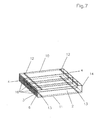
- FIG. 7 shows a housing 2 for a humidifier 1 in an embodiment in accordance with the previous figures.
- Housing 2 is rectangular and flattened.
- the two frontal faces 6, 14 are completely open.
- Four bundles 16 are arranged in housing 2, a large number of fibres 3 being arranged in each of the bundles 16.
- First air stream 4, which flows inside fibres 3, may be guided via frontal faces 6, 14.
- Slit-like apertures 12 and 13 are provided on both the top 10 and bottom 11 thereof.
- Second air stream 5 may be guided via slit-like apertures 12, 13.
- Figure 8 shows a bundle 16 in which a multiplicity of fibres 3 are combined.
- Bundle 16 has a ring 17 on its frontal faces, via which the fibres are stabilised.
- Ring 17 is made from a resin and the fibres are stuck together thereby, the spaces between the fibres are penetrated by the resin and thus sealed airtight.
- the outer circumference of ring 17 forms a circumferential seal. In this way, bundles 16 are arranged in the housing in such manner that first air stream 4 and second air stream 5 are unable to mix.
Landscapes
- Chemical & Material Sciences (AREA)
- Engineering & Computer Science (AREA)
- General Chemical & Material Sciences (AREA)
- Chemical Kinetics & Catalysis (AREA)
- Sustainable Energy (AREA)
- Life Sciences & Earth Sciences (AREA)
- Sustainable Development (AREA)
- Electrochemistry (AREA)
- Manufacturing & Machinery (AREA)
- Analytical Chemistry (AREA)
- Oil, Petroleum & Natural Gas (AREA)
- Combustion & Propulsion (AREA)
- Mechanical Engineering (AREA)
- General Engineering & Computer Science (AREA)
- Air Humidification (AREA)
- Fuel Cell (AREA)
Claims (11)
- Luftbefeuchter (1), der mindestens ein Gehäuse (2) enthält, in dem mehrere Fasern (3), die als wasserdurchlässige, hohle Fasermembranen konfiguriert sind, angeordnet sind, wobei ein erster Luftstrom (4) innerhalb der Faser (3) verlaufen kann und ein zweiter Luftstrom (5) außerhalb der Faser (3) verlaufen kann, wobei das Gehäuse abgeflacht ist, wobei ein erster Kollektor (7) auf mindestens einer Vorderseite (6) des Gehäuses (2) angeordnet ist, wobei der erste Luftstrom (4) über den ersten Kollektor (7) in die Fasern (3) hinein oder aus den Fasern (3) heraus verlaufen kann, wobei mindestens ein zweiter Kollektor (8) dem Gehäuse (2) zugeordnet ist, wobei der zweite Luftstrom (5) über den zweiten Kollektor (8) in die Fasern (3) hinein oder aus den Fasern (3) heraus verlaufen kann, dadurch gekennzeichet, dass der zweite Kollektor (8) mindestens teilweise das Gehäuse (2) an der Oberseite und an der Unterseite (10, 11) umgibt.
- Luftbefeuchter nach Anspruch 1 oder 2, dadurch gekennzeichnet, dass der erste Luftstrom (4) als ein befeuchtender Luftstrom, der Dampf enthält, für eine Einheit stromabwärts dient, und der zweite Luftstrom (5) als ein Luftzufuhrstrom dient.
- Luftbefeuchter nach Anspruch 1 oder 2, dadurch gekennzeichnet, dass der erste Luftstrom (4) und der zweite Luftstrom (5) in entgegengesetzte Richtungen geleitet werden können.
- Luftbefeuchter nach Anspruch 1, dadurch gekennzeichnet, dass der zweite Kollektor (8) mindestens teilweise den ersten Kollektor (7) umgibt.
- Luftbefeuchter nach einem der Ansprüche 1 oder 4, dadurch gekennzeichet, dass der zweite Kollektor das Gehäuse in einer klemmähnlichen Art umgibt.
- Luftbefeuchter nach einem der Ansprüche 1 oder 4, dadurch gekennzeichnet, dass der zweite Kollektor das Gehäuse in der Art eines Rings umgibt.
- Luftbefeuchter nach einem der Ansprüche 1 bis 6, dadurch gekennzeichnet, dass mindestens eine Vorderseite (6) des Gehäuses (2) mindestens eine schlitzartige Öffnung (9) aufweist.
- Luftbefeuchter nach Anspruch 6, dadurch gekennzeichnet, dass eine schlitzartige Öffnung (12, 13) in jedem Bereich bereitgestellt ist, der von dem zweiten Kollektor (8) an der Oberseite und an der Unterseite (10, 11) des Gehäuses (2) umschlossen ist.
- Luftbefeuchter nach einem der Ansprüche 7 oder 8, dadurch gekennzeichnet, dass sich die schlitzartige Öffnung (9, 12, 13) im Wesentlichen quer über den vollen Bereich des Gehäuses (2) erstreckt.
- Luftbefeuchter nach einem der Ansprüche 1 bis 9, dadurch gekennzeichnet, dass zwei zweite Kollektoren (8) bereitgestellt sind und dass sie über eine anpassbare Umgehung (15) leitend miteinander kommunizieren.
- Luftbefeuchter nach einem der Ansprüche 1 bis 10, dadurch gekennzeichnet, dass die Strömung des zweiten Luftstroms (5) innerhalb des Gehäuses (2) in einer laminaren Art geleitet werden kann.
Applications Claiming Priority (3)
| Application Number | Priority Date | Filing Date | Title |
|---|---|---|---|
| DE102005009850 | 2005-03-01 | ||
| DE102005028717A DE102005028717B4 (de) | 2005-03-01 | 2005-06-20 | Befeuchter |
| PCT/EP2006/001712 WO2006092242A1 (en) | 2005-03-01 | 2006-02-24 | Humidifier |
Publications (2)
| Publication Number | Publication Date |
|---|---|
| EP1853373A1 EP1853373A1 (de) | 2007-11-14 |
| EP1853373B1 true EP1853373B1 (de) | 2015-09-02 |
Family
ID=36616809
Family Applications (1)
| Application Number | Title | Priority Date | Filing Date |
|---|---|---|---|
| EP06723103.5A Expired - Lifetime EP1853373B1 (de) | 2005-03-01 | 2006-02-24 | Luftbefeuchter |
Country Status (4)
| Country | Link |
|---|---|
| US (1) | US8181943B2 (de) |
| EP (1) | EP1853373B1 (de) |
| DE (1) | DE102005028717B4 (de) |
| WO (1) | WO2006092242A1 (de) |
Families Citing this family (16)
| Publication number | Priority date | Publication date | Assignee | Title |
|---|---|---|---|---|
| KR101278398B1 (ko) * | 2007-08-01 | 2013-06-24 | 코오롱인더스트리 주식회사 | 중공사막 및 그 제조방법 |
| DE102008034406B4 (de) * | 2008-07-23 | 2023-05-17 | Cellcentric Gmbh & Co. Kg | Befeuchtereinrichtung zum Befeuchten eines Fluids in einem Brennstoffzellensystem |
| DE102008034407A1 (de) * | 2008-07-23 | 2010-01-28 | Carl Freudenberg Kg | Befeuchtermodul für ein Brennstoffzellensystem |
| KR101185326B1 (ko) * | 2010-03-31 | 2012-09-26 | 코오롱인더스트리 주식회사 | 연료전지용 가습기 |
| JP5783321B2 (ja) * | 2012-03-13 | 2015-09-24 | 日産自動車株式会社 | 加湿器 |
| DE102013004637A1 (de) | 2013-03-16 | 2014-09-18 | Volkswagen Aktiengesellschaft | Befeuchtungseinrichtung zur Befeuchtung eines Prozessgases, Brennstoffzellenanordnung umfassend eine solche sowie Fahrzeug |
| DE202013009357U1 (de) | 2013-06-27 | 2015-01-16 | Dana Canada Corporation | Integrierte Gasmanagementvorrichtung für ein Brennstoffzellensystem |
| KR101592423B1 (ko) * | 2014-08-01 | 2016-02-18 | 현대자동차주식회사 | 연료전지용 가습기 및 이를 포함하는 연료전지 시스템 |
| DE102015122144A1 (de) * | 2015-12-17 | 2017-06-22 | Volkswagen Ag | Befeuchter mit integriertem Wasserabscheider für ein Brennstoffzellensystem, Brennstoffzellensystem sowie Fahrzeug mit einem solchen |
| DE102017116266A1 (de) * | 2017-07-19 | 2019-01-24 | Beko Technologies Gmbh | Druckluftmembrantrockner mit Mischluftregelung |
| DE102017218502A1 (de) * | 2017-10-17 | 2019-04-18 | Volkswagen Aktiengesellschaft | Feuchtigkeitstauschmodul für ein Brennstoffzellensystem, Brennstoffzellensystem |
| KR102805455B1 (ko) | 2019-08-14 | 2025-05-15 | 현대자동차주식회사 | 연료전지용 가습기 |
| KR102704080B1 (ko) * | 2019-11-29 | 2024-09-05 | 코오롱인더스트리 주식회사 | 연료전지용 가습기 |
| CA3226562A1 (en) | 2021-08-23 | 2023-03-02 | Parker-Hannifin Corporation | Fuel cell humidificaton potting adhesive shroud |
| US12209823B2 (en) | 2022-01-21 | 2025-01-28 | Hamilton Sundstrand Corporation | Heat exchanger header structures |
| WO2025049517A1 (en) | 2023-08-29 | 2025-03-06 | Parker-Hannifin Corporation | Mixing hollow fiber sizes for improved humidifier performance |
Family Cites Families (8)
| Publication number | Priority date | Publication date | Assignee | Title |
|---|---|---|---|---|
| JPH0533975A (ja) | 1991-07-30 | 1993-02-09 | Daikin Ind Ltd | 加湿器 |
| JPH07245116A (ja) * | 1994-03-07 | 1995-09-19 | Toyota Motor Corp | 燃料電池 |
| DE10102358B4 (de) * | 2000-01-19 | 2007-09-13 | Honda Giken Kogyo K.K. | Befeuchter für eine Brennstoffzelle |
| US6953635B2 (en) * | 2000-10-04 | 2005-10-11 | Honda Giken Kogyo Kabushiki Kaisha | Humidifier for fuel cell |
| JP3907936B2 (ja) * | 2000-10-05 | 2007-04-18 | 本田技研工業株式会社 | 燃料電池用加湿装置 |
| JP4610715B2 (ja) | 2000-11-06 | 2011-01-12 | Nok株式会社 | 加湿装置 |
| JP5189719B2 (ja) * | 2001-01-22 | 2013-04-24 | 本田技研工業株式会社 | 燃料電池システム |
| DE10244707A1 (de) * | 2002-09-24 | 2004-04-01 | Daimlerchrysler Ag | Vorrichtung zum Austausch von Feuchtigkeit zwischen einem feuchten und einem trockenen Gasstrom |
-
2005
- 2005-06-20 DE DE102005028717A patent/DE102005028717B4/de not_active Expired - Fee Related
-
2006
- 2006-02-24 US US11/884,167 patent/US8181943B2/en active Active
- 2006-02-24 EP EP06723103.5A patent/EP1853373B1/de not_active Expired - Lifetime
- 2006-02-24 WO PCT/EP2006/001712 patent/WO2006092242A1/en not_active Ceased
Also Published As
| Publication number | Publication date |
|---|---|
| US20090121366A1 (en) | 2009-05-14 |
| DE102005028717A1 (de) | 2006-09-07 |
| DE102005028717B4 (de) | 2013-07-25 |
| EP1853373A1 (de) | 2007-11-14 |
| US8181943B2 (en) | 2012-05-22 |
| WO2006092242A1 (en) | 2006-09-08 |
Similar Documents
| Publication | Publication Date | Title |
|---|---|---|
| US8181943B2 (en) | Humidifier | |
| US10668432B2 (en) | Hollow fiber membrane module | |
| JP5564580B2 (ja) | 燃料電池用加湿器 | |
| JP6602870B2 (ja) | 中空糸膜カートリッジ型加湿モジュール及びその製造方法 | |
| CN111200139A (zh) | 用于对流体进行加湿的加湿模块 | |
| EP3124106B1 (de) | Hohlfasermembranmodul | |
| EP1925054A1 (de) | Befeuchtungssystem für eine brennstoffzelle | |
| US12611632B2 (en) | Humidifier | |
| JP5211855B2 (ja) | 燃料電池の加湿装置 | |
| CN111683730B (zh) | 中空纤维膜组件 | |
| KR20150113503A (ko) | 유체교환막 모듈 | |
| KR101428186B1 (ko) | 연료전지용 막 가습 장치 | |
| CN212517267U (zh) | 一种燃料电池系统及其气体增湿器 | |
| JP5746039B2 (ja) | 燃料電池装置に連結するための供給アセンブリ及びこの供給アセンブリを備える燃料電池システム | |
| JP7653515B2 (ja) | 中空糸膜モジュール | |
| JP2010127582A (ja) | 加湿装置 | |
| JP4441131B2 (ja) | 加湿モジュールの形状設定方法 | |
| JP2010071618A (ja) | 加湿装置 | |
| CN214672701U (zh) | 一种燃料电池高效膜加湿器 | |
| JP7653514B2 (ja) | 中空糸膜モジュール | |
| US20050247200A1 (en) | Moisture exchange module containing a bundle of moisture-permeable hollow fiber membranes | |
| JP2007059090A (ja) | 燃料電池用加湿システム | |
| JP2018199098A (ja) | 膜分離装置 | |
| CN119965298A (zh) | 一种燃料电池膜增湿器 | |
| JP2024158575A (ja) | 除湿装置 |
Legal Events
| Date | Code | Title | Description |
|---|---|---|---|
| PUAI | Public reference made under article 153(3) epc to a published international application that has entered the european phase |
Free format text: ORIGINAL CODE: 0009012 |
|
| 17P | Request for examination filed |
Effective date: 20070719 |
|
| AK | Designated contracting states |
Kind code of ref document: A1 Designated state(s): AT BE BG CH CY CZ DE DK EE ES FI FR GB GR HU IE IS IT LI LT LU LV MC NL PL PT RO SE SI SK TR |
|
| DAX | Request for extension of the european patent (deleted) | ||
| REG | Reference to a national code |
Ref country code: DE Ref legal event code: R079 Ref document number: 602006046498 Country of ref document: DE Free format text: PREVIOUS MAIN CLASS: B01D0053220000 Ipc: B01D0063020000 |
|
| GRAP | Despatch of communication of intention to grant a patent |
Free format text: ORIGINAL CODE: EPIDOSNIGR1 |
|
| RIC1 | Information provided on ipc code assigned before grant |
Ipc: B01D 53/26 20060101ALI20150302BHEP Ipc: B01D 63/02 20060101AFI20150302BHEP Ipc: F24F 6/02 20060101ALI20150302BHEP Ipc: F24F 3/14 20060101ALI20150302BHEP Ipc: B01D 53/22 20060101ALI20150302BHEP Ipc: H01M 8/04 20060101ALI20150302BHEP |
|
| INTG | Intention to grant announced |
Effective date: 20150320 |
|
| GRAS | Grant fee paid |
Free format text: ORIGINAL CODE: EPIDOSNIGR3 |
|
| GRAA | (expected) grant |
Free format text: ORIGINAL CODE: 0009210 |
|
| AK | Designated contracting states |
Kind code of ref document: B1 Designated state(s): AT BE BG CH CY CZ DE DK EE ES FI FR GB GR HU IE IS IT LI LT LU LV MC NL PL PT RO SE SI SK TR |
|
| REG | Reference to a national code |
Ref country code: GB Ref legal event code: FG4D |
|
| REG | Reference to a national code |
Ref country code: AT Ref legal event code: REF Ref document number: 746188 Country of ref document: AT Kind code of ref document: T Effective date: 20150915 Ref country code: CH Ref legal event code: EP |
|
| REG | Reference to a national code |
Ref country code: IE Ref legal event code: FG4D |
|
| REG | Reference to a national code |
Ref country code: DE Ref legal event code: R096 Ref document number: 602006046498 Country of ref document: DE |
|
| REG | Reference to a national code |
Ref country code: AT Ref legal event code: MK05 Ref document number: 746188 Country of ref document: AT Kind code of ref document: T Effective date: 20150902 |
|
| PG25 | Lapsed in a contracting state [announced via postgrant information from national office to epo] |
Ref country code: GR Free format text: LAPSE BECAUSE OF FAILURE TO SUBMIT A TRANSLATION OF THE DESCRIPTION OR TO PAY THE FEE WITHIN THE PRESCRIBED TIME-LIMIT Effective date: 20151203 Ref country code: LT Free format text: LAPSE BECAUSE OF FAILURE TO SUBMIT A TRANSLATION OF THE DESCRIPTION OR TO PAY THE FEE WITHIN THE PRESCRIBED TIME-LIMIT Effective date: 20150902 Ref country code: LV Free format text: LAPSE BECAUSE OF FAILURE TO SUBMIT A TRANSLATION OF THE DESCRIPTION OR TO PAY THE FEE WITHIN THE PRESCRIBED TIME-LIMIT Effective date: 20150902 Ref country code: FI Free format text: LAPSE BECAUSE OF FAILURE TO SUBMIT A TRANSLATION OF THE DESCRIPTION OR TO PAY THE FEE WITHIN THE PRESCRIBED TIME-LIMIT Effective date: 20150902 |
|
| REG | Reference to a national code |
Ref country code: LT Ref legal event code: MG4D Ref country code: NL Ref legal event code: MP Effective date: 20150902 |
|
| PG25 | Lapsed in a contracting state [announced via postgrant information from national office to epo] |
Ref country code: ES Free format text: LAPSE BECAUSE OF FAILURE TO SUBMIT A TRANSLATION OF THE DESCRIPTION OR TO PAY THE FEE WITHIN THE PRESCRIBED TIME-LIMIT Effective date: 20150902 Ref country code: PL Free format text: LAPSE BECAUSE OF FAILURE TO SUBMIT A TRANSLATION OF THE DESCRIPTION OR TO PAY THE FEE WITHIN THE PRESCRIBED TIME-LIMIT Effective date: 20150902 Ref country code: SE Free format text: LAPSE BECAUSE OF FAILURE TO SUBMIT A TRANSLATION OF THE DESCRIPTION OR TO PAY THE FEE WITHIN THE PRESCRIBED TIME-LIMIT Effective date: 20150902 Ref country code: AT Free format text: LAPSE BECAUSE OF FAILURE TO SUBMIT A TRANSLATION OF THE DESCRIPTION OR TO PAY THE FEE WITHIN THE PRESCRIBED TIME-LIMIT Effective date: 20150902 |
|
| PG25 | Lapsed in a contracting state [announced via postgrant information from national office to epo] |
Ref country code: EE Free format text: LAPSE BECAUSE OF FAILURE TO SUBMIT A TRANSLATION OF THE DESCRIPTION OR TO PAY THE FEE WITHIN THE PRESCRIBED TIME-LIMIT Effective date: 20150902 Ref country code: IT Free format text: LAPSE BECAUSE OF FAILURE TO SUBMIT A TRANSLATION OF THE DESCRIPTION OR TO PAY THE FEE WITHIN THE PRESCRIBED TIME-LIMIT Effective date: 20150902 Ref country code: IS Free format text: LAPSE BECAUSE OF FAILURE TO SUBMIT A TRANSLATION OF THE DESCRIPTION OR TO PAY THE FEE WITHIN THE PRESCRIBED TIME-LIMIT Effective date: 20160102 Ref country code: CZ Free format text: LAPSE BECAUSE OF FAILURE TO SUBMIT A TRANSLATION OF THE DESCRIPTION OR TO PAY THE FEE WITHIN THE PRESCRIBED TIME-LIMIT Effective date: 20150902 Ref country code: SK Free format text: LAPSE BECAUSE OF FAILURE TO SUBMIT A TRANSLATION OF THE DESCRIPTION OR TO PAY THE FEE WITHIN THE PRESCRIBED TIME-LIMIT Effective date: 20150902 Ref country code: NL Free format text: LAPSE BECAUSE OF FAILURE TO SUBMIT A TRANSLATION OF THE DESCRIPTION OR TO PAY THE FEE WITHIN THE PRESCRIBED TIME-LIMIT Effective date: 20150902 |
|
| PG25 | Lapsed in a contracting state [announced via postgrant information from national office to epo] |
Ref country code: RO Free format text: LAPSE BECAUSE OF FAILURE TO SUBMIT A TRANSLATION OF THE DESCRIPTION OR TO PAY THE FEE WITHIN THE PRESCRIBED TIME-LIMIT Effective date: 20150902 Ref country code: BE Free format text: LAPSE BECAUSE OF NON-PAYMENT OF DUE FEES Effective date: 20160229 Ref country code: PT Free format text: LAPSE BECAUSE OF FAILURE TO SUBMIT A TRANSLATION OF THE DESCRIPTION OR TO PAY THE FEE WITHIN THE PRESCRIBED TIME-LIMIT Effective date: 20160104 |
|
| REG | Reference to a national code |
Ref country code: DE Ref legal event code: R097 Ref document number: 602006046498 Country of ref document: DE |
|
| PLBE | No opposition filed within time limit |
Free format text: ORIGINAL CODE: 0009261 |
|
| STAA | Information on the status of an ep patent application or granted ep patent |
Free format text: STATUS: NO OPPOSITION FILED WITHIN TIME LIMIT |
|
| 26N | No opposition filed |
Effective date: 20160603 |
|
| PG25 | Lapsed in a contracting state [announced via postgrant information from national office to epo] |
Ref country code: SI Free format text: LAPSE BECAUSE OF FAILURE TO SUBMIT A TRANSLATION OF THE DESCRIPTION OR TO PAY THE FEE WITHIN THE PRESCRIBED TIME-LIMIT Effective date: 20150902 Ref country code: DK Free format text: LAPSE BECAUSE OF FAILURE TO SUBMIT A TRANSLATION OF THE DESCRIPTION OR TO PAY THE FEE WITHIN THE PRESCRIBED TIME-LIMIT Effective date: 20150902 |
|
| PG25 | Lapsed in a contracting state [announced via postgrant information from national office to epo] |
Ref country code: LU Free format text: LAPSE BECAUSE OF FAILURE TO SUBMIT A TRANSLATION OF THE DESCRIPTION OR TO PAY THE FEE WITHIN THE PRESCRIBED TIME-LIMIT Effective date: 20160224 Ref country code: MC Free format text: LAPSE BECAUSE OF FAILURE TO SUBMIT A TRANSLATION OF THE DESCRIPTION OR TO PAY THE FEE WITHIN THE PRESCRIBED TIME-LIMIT Effective date: 20150902 |
|
| REG | Reference to a national code |
Ref country code: CH Ref legal event code: PL |
|
| GBPC | Gb: european patent ceased through non-payment of renewal fee |
Effective date: 20160224 |
|
| PG25 | Lapsed in a contracting state [announced via postgrant information from national office to epo] |
Ref country code: LI Free format text: LAPSE BECAUSE OF NON-PAYMENT OF DUE FEES Effective date: 20160229 Ref country code: CH Free format text: LAPSE BECAUSE OF NON-PAYMENT OF DUE FEES Effective date: 20160229 |
|
| REG | Reference to a national code |
Ref country code: FR Ref legal event code: ST Effective date: 20161028 |
|
| REG | Reference to a national code |
Ref country code: IE Ref legal event code: MM4A |
|
| PG25 | Lapsed in a contracting state [announced via postgrant information from national office to epo] |
Ref country code: BE Free format text: LAPSE BECAUSE OF FAILURE TO SUBMIT A TRANSLATION OF THE DESCRIPTION OR TO PAY THE FEE WITHIN THE PRESCRIBED TIME-LIMIT Effective date: 20150902 |
|
| PG25 | Lapsed in a contracting state [announced via postgrant information from national office to epo] |
Ref country code: IE Free format text: LAPSE BECAUSE OF NON-PAYMENT OF DUE FEES Effective date: 20160224 Ref country code: GB Free format text: LAPSE BECAUSE OF NON-PAYMENT OF DUE FEES Effective date: 20160224 Ref country code: FR Free format text: LAPSE BECAUSE OF NON-PAYMENT OF DUE FEES Effective date: 20160229 |
|
| PG25 | Lapsed in a contracting state [announced via postgrant information from national office to epo] |
Ref country code: CY Free format text: LAPSE BECAUSE OF FAILURE TO SUBMIT A TRANSLATION OF THE DESCRIPTION OR TO PAY THE FEE WITHIN THE PRESCRIBED TIME-LIMIT Effective date: 20150902 Ref country code: HU Free format text: LAPSE BECAUSE OF FAILURE TO SUBMIT A TRANSLATION OF THE DESCRIPTION OR TO PAY THE FEE WITHIN THE PRESCRIBED TIME-LIMIT; INVALID AB INITIO Effective date: 20060224 |
|
| PG25 | Lapsed in a contracting state [announced via postgrant information from national office to epo] |
Ref country code: TR Free format text: LAPSE BECAUSE OF FAILURE TO SUBMIT A TRANSLATION OF THE DESCRIPTION OR TO PAY THE FEE WITHIN THE PRESCRIBED TIME-LIMIT Effective date: 20150902 |
|
| PG25 | Lapsed in a contracting state [announced via postgrant information from national office to epo] |
Ref country code: BG Free format text: LAPSE BECAUSE OF FAILURE TO SUBMIT A TRANSLATION OF THE DESCRIPTION OR TO PAY THE FEE WITHIN THE PRESCRIBED TIME-LIMIT Effective date: 20150902 |
|
| PGFP | Annual fee paid to national office [announced via postgrant information from national office to epo] |
Ref country code: DE Payment date: 20200303 Year of fee payment: 15 |
|
| REG | Reference to a national code |
Ref country code: DE Ref legal event code: R119 Ref document number: 602006046498 Country of ref document: DE |
|
| PG25 | Lapsed in a contracting state [announced via postgrant information from national office to epo] |
Ref country code: DE Free format text: LAPSE BECAUSE OF NON-PAYMENT OF DUE FEES Effective date: 20210901 |