EP3124106B1 - Hohlfasermembranmodul - Google Patents
Hohlfasermembranmodul Download PDFInfo
- Publication number
- EP3124106B1 EP3124106B1 EP15768607.2A EP15768607A EP3124106B1 EP 3124106 B1 EP3124106 B1 EP 3124106B1 EP 15768607 A EP15768607 A EP 15768607A EP 3124106 B1 EP3124106 B1 EP 3124106B1
- Authority
- EP
- European Patent Office
- Prior art keywords
- hollow fiber
- fluid
- fiber membrane
- housing
- porous tube
- Prior art date
- Legal status (The legal status is an assumption and is not a legal conclusion. Google has not performed a legal analysis and makes no representation as to the accuracy of the status listed.)
- Active
Links
Images


Classifications
-
- B—PERFORMING OPERATIONS; TRANSPORTING
- B01—PHYSICAL OR CHEMICAL PROCESSES OR APPARATUS IN GENERAL
- B01D—SEPARATION
- B01D63/00—Apparatus in general for separation processes using semi-permeable membranes
- B01D63/02—Hollow fibre modules
- B01D63/04—Hollow fibre modules comprising multiple hollow fibre assemblies
-
- B—PERFORMING OPERATIONS; TRANSPORTING
- B01—PHYSICAL OR CHEMICAL PROCESSES OR APPARATUS IN GENERAL
- B01D—SEPARATION
- B01D63/00—Apparatus in general for separation processes using semi-permeable membranes
- B01D63/02—Hollow fibre modules
-
- B—PERFORMING OPERATIONS; TRANSPORTING
- B01—PHYSICAL OR CHEMICAL PROCESSES OR APPARATUS IN GENERAL
- B01D—SEPARATION
- B01D63/00—Apparatus in general for separation processes using semi-permeable membranes
- B01D63/02—Hollow fibre modules
- B01D63/033—Specific distribution of fibres within one potting or tube-sheet
-
- B—PERFORMING OPERATIONS; TRANSPORTING
- B01—PHYSICAL OR CHEMICAL PROCESSES OR APPARATUS IN GENERAL
- B01D—SEPARATION
- B01D63/00—Apparatus in general for separation processes using semi-permeable membranes
- B01D63/02—Hollow fibre modules
- B01D63/04—Hollow fibre modules comprising multiple hollow fibre assemblies
- B01D63/043—Hollow fibre modules comprising multiple hollow fibre assemblies with separate tube sheets
-
- H—ELECTRICITY
- H01—ELECTRIC ELEMENTS
- H01M—PROCESSES OR MEANS, e.g. BATTERIES, FOR THE DIRECT CONVERSION OF CHEMICAL ENERGY INTO ELECTRICAL ENERGY
- H01M8/00—Fuel cells; Manufacture thereof
- H01M8/04—Auxiliary arrangements, e.g. for control of pressure or for circulation of fluids
- H01M8/04082—Arrangements for control of reactant parameters, e.g. pressure or concentration
- H01M8/04089—Arrangements for control of reactant parameters, e.g. pressure or concentration of gaseous reactants
- H01M8/04119—Arrangements for control of reactant parameters, e.g. pressure or concentration of gaseous reactants with simultaneous supply or evacuation of electrolyte; Humidifying or dehumidifying
- H01M8/04126—Humidifying
- H01M8/04149—Humidifying by diffusion, e.g. making use of membranes
-
- B—PERFORMING OPERATIONS; TRANSPORTING
- B01—PHYSICAL OR CHEMICAL PROCESSES OR APPARATUS IN GENERAL
- B01D—SEPARATION
- B01D2313/00—Details relating to membrane modules or apparatus
- B01D2313/08—Flow guidance means within the module or the apparatus
-
- B—PERFORMING OPERATIONS; TRANSPORTING
- B01—PHYSICAL OR CHEMICAL PROCESSES OR APPARATUS IN GENERAL
- B01D—SEPARATION
- B01D2313/00—Details relating to membrane modules or apparatus
- B01D2313/08—Flow guidance means within the module or the apparatus
- B01D2313/083—Bypass routes
-
- B—PERFORMING OPERATIONS; TRANSPORTING
- B01—PHYSICAL OR CHEMICAL PROCESSES OR APPARATUS IN GENERAL
- B01D—SEPARATION
- B01D2313/00—Details relating to membrane modules or apparatus
- B01D2313/20—Specific housing
- B01D2313/203—Open housings
- B01D2313/2031—Frame or cage-like structures
-
- B—PERFORMING OPERATIONS; TRANSPORTING
- B01—PHYSICAL OR CHEMICAL PROCESSES OR APPARATUS IN GENERAL
- B01D—SEPARATION
- B01D2313/00—Details relating to membrane modules or apparatus
- B01D2313/26—Specific gas distributors or gas intakes
-
- B—PERFORMING OPERATIONS; TRANSPORTING
- B01—PHYSICAL OR CHEMICAL PROCESSES OR APPARATUS IN GENERAL
- B01D—SEPARATION
- B01D2319/00—Membrane assemblies within one housing
- B01D2319/04—Elements in parallel
-
- Y—GENERAL TAGGING OF NEW TECHNOLOGICAL DEVELOPMENTS; GENERAL TAGGING OF CROSS-SECTIONAL TECHNOLOGIES SPANNING OVER SEVERAL SECTIONS OF THE IPC; TECHNICAL SUBJECTS COVERED BY FORMER USPC CROSS-REFERENCE ART COLLECTIONS [XRACs] AND DIGESTS
- Y02—TECHNOLOGIES OR APPLICATIONS FOR MITIGATION OR ADAPTATION AGAINST CLIMATE CHANGE
- Y02E—REDUCTION OF GREENHOUSE GAS [GHG] EMISSIONS, RELATED TO ENERGY GENERATION, TRANSMISSION OR DISTRIBUTION
- Y02E60/00—Enabling technologies; Technologies with a potential or indirect contribution to GHG emissions mitigation
- Y02E60/30—Hydrogen technology
- Y02E60/50—Fuel cells
Definitions
- the present invention relates to a hollow fiber membrane module and, more particularly, to a hollow fiber membrane module which removes a region, into which a fluid flowing outside a hollow fiber membrane bundle has difficulty in permeating, so that the fluid uniformly flows and thus, even if hollow flow membranes are highly integrated, performance of the hollow fiber membrane module may be maximized.
- Fuel cells may be generally classified into a polymer electrolyte membrane fuel cell (PEMFC), a phosphoric acid fuel cell (PAFC), a molten carbonate fuel cell (MCFC), a solid oxide fuel cell (SOFC), an alkaline fuel cell (AFC), etc. according to kinds of electrolytes used.
- the respective fuel cells are basically operated by the same principle, but kinds of fuels used, operating temperatures, catalysts, electrolytes, etc., of the respective fuel cells are different. Thereamong, it is known that the PEMFC is operated at a low temperature, as compared to other fuel cells, has high power density, is small-sized, and may thus be promising as small mounting-type power generation equipment but also transportation systems.
- PEMFC polymer electrolyte membrane or a proton exchange membrane (PEM) of a membrane-electrolyte assembly (MEA) so as to maintain a desired water content.
- PEM polymer electrolyte membrane or a proton exchange membrane (PEM) of a membrane-electrolyte assembly
- a bubbler humidification method in which moisture is supplied by filling a pressure vessel with water and then causing target gas to pass through a diffuser
- a direct injection method in which an amount of supply moisture necessary for fuel cell reaction is calculated and then moisture is supplied directly to a gas flow pipe through a solenoid valve
- 3) a humidification membrane method in which moisture is supplied to a gas fluidized bed using a polymeric separation membrane.
- the humidification membrane method in which vapor is fed to gas supplied to a polymer electrolyte membrane using a membrane selectively transmitting only vapor included in exhaust gas so as to humidify the polymer electrolyte membrane, is advantageous in that a humidifier may be lightweight and small.
- hollow fiber membranes in which, if a module is formed, a transmission area per unit volume is large are preferably used. That is, if a humidifier is manufactured using the hollow fiber membranes, high integration of the hollow fiber membranes having a large contact surface area is achieved and a fuel cell may be sufficiently humidified at a small capacity, a low-cost material may be used, and moisture and heat included in unreacted gas of a high temperature discharged from the fuel cell may be collected and reused through the humidifier.
- the thickness of a hollow fiber membrane bundle is restricted or the hollow fiber membrane bundle is divided.
- another problem i.e., a limit on mounting of the hollow fiber membranes in a confined space, may be caused.
- US2013065140 is a membrane humidifier for a fuel cell wherein humidification performance is improved by using diaphragms.
- EP1137478 discloses a hollow fibre fluid separation moduile wherein a porous tube is used as a permeate flow channel to improve permeate flow.
- the porous tubes is disposed so that the length direction of the porous tubes coincides with the length direction of the hollow fiber membrane bundles.
- the diameter of the pores of the porous tubes is 1 to 10 mm.
- a ratio of the whole area of the pores of the porous tube to the whole area of the side surface of the porous tube may be 10 to 50% by area.
- the cross-section of the housing may have a circular shape or a polygonal shape.
- the housing further includes a housing body having both ends opened and including the first fluid inlet and the first fluid outlet formed on the outer surface thereof, and housing caps combined with the respective ends of the housing body and including the second fluid inlet and the second fluid outlet.
- the hollow fiber membrane module further includes potting parts configured to fix both ends of the hollow fiber membranes to the housing and contacting both ends of the housing so as to be sealable.
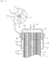
- a hollow fiber membrane module 10 includes a housing 1, hollow fiber membrane bundles 4, and potting parts 2.
- the housing 1 forms the external appearance of the hollow fiber membrane module 10.
- the housing 1 includes a housing body 11 and housing caps 5 and may be an integral type in which the housing body 11 and the housing caps 5 are combined.
- the housing body 11 and the housing caps 5 may be formed of hard plastic, such as polycarbonate, or metal.
- the cross-sections of the housing body 11 and the housing caps 5 in the width direction may have a polygonal shape, as exemplarily shown in FIGS. 1 and 2 , or have a circular shape, as exemplarily shown in FIG. 3 .
- the polygonal shape may be a rectangle, a square, a trapezoid, a parallelogram, a pentagon or a hexagon, and the polygonal shape may be a shape having rounded corners.
- the circular shape may be an oval.
- the housing further includes circumferential parts 12 formed at both ends of the housing body 11 to extend the circumference of the housing body 11. In this case, both opened ends of the circumferential parts 12 are embedded in the potting parts 2 and the potting parts 2 are surrounded by the circumferential parts 12.
- a second fluid inlet 121 to which a second fluid is supplied and a second fluid outlet 122 from which the second fluid is discharged are formed on the circumferential parts 12.
- the hollow fiber membranes 41 may be formed of known materials and a detailed description thereof will thus be omitted.
- the housing caps 5 are combined with both ends of the housing body 11.
- a first fluid inlet 51 and a first fluid outlet 52 are formed on the housing caps 5.
- a first fluid introduced into the first fluid inlet 51 of one housing cap 5 passes through inner ducts of the hollow fiber membranes 41 and is discharged from the first fluid outlet 52 of the other housing cap 5.
- the potting part 2 may be formed so as to be inclined upward from an approximately central portion of a tip 12a of the circumferential part 12 to the center of the housing body 11, and the hollow fiber membranes 41 pass through the potting part 2 so that the ducts of the hollow fiber membranes 41 are exposed at the end of the potting part 2.
- a sealing member S may be attached to the tip 12a of the circumferential part 12, which is not shielded by the potting part 2, and the housing cap 5 may apply pressure to the sealing member S and thus be combined with the housing body 11.
- the hollow fiber membrane module 10 includes a plurality of hollow fiber membrane bundles 4 and diaphragms 9 to divide the hollow fiber membrane bundles 4 from each other. Fluid flow holes 8 are formed in the diaphragms 9 so that the second fluid may pass through the diaphragms 9 through the fluid flow holes 8 and flow to the outside of the hollow fiber membrane bundles 4.
- the second fluid is supplied to one circumferential part 12 of the housing body 11 through the second fluid inlet 121 of the housing body 11, passes through the diaphragms 9 through the fluid flow holes 8, each of which is formed at one side of each of the diaphragms 9, flows to the outside of the hollow fiber membranes 41, is discharged to the other circumferential part 12 of the housing body 11 through the fluid flow holes 8, each of which is formed at the other side of each of the diaphragms 9, and is discharged to the outside of the housing 1 through the second fluid outlet 122 of the housing body 11.
- the second fluid may be introduced into the second fluid outlet 122 and then be discharged from the second fluid inlet 121. That is, the first fluid and the second fluid may flow in opposite directions or flow in the same direction. The first fluid and the second fluid respectively flow inside and outside the hollow fiber membranes 41 and exchange moisture through the hollow fiber membranes 41.
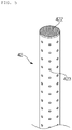
- the hollow fiber membrane module 10 includes a plurality of hollow fiber membrane bundles 4, each hollow fiber membrane bundle 4 may include one porous tube 42 or include a plurality of porous tubes 42.
- the porous tubes 42 may be disposed at random positions between the hollow fiber membranes 41 or be disposed at designated intervals.
- the cross-section of the porous tube 42 in the width direction may have a circular shape, as exemplarily shown in FIG. 5 , or have a polygonal shape, as exemplarily shown in FIG. 6 .
- the circular shape may be an oval
- the polygonal shape may be a rectangle, a square, a trapezoid, a parallelogram, a pentagon or a hexagon, and be a shape having rounded corners.
- the diameter of the pores 423 of the porous tube 42 is 1 to 10 mm, preferably 2 to 8 mm, and more preferably 3 to 5 mm. If the diameter of the pores 423 is less than 1 mm, a fluid flow amount through the pores 423 of the porous tube 42 may be small and, if the diameter of the pores 423 exceeds 10 mm, a fluid flow amount may be excessively increased and cause concentration of inflow fluid.
- a fluid flow amount through the pores 423 of the porous tube 42 may be small and, if the whole area of the pores 423 of the porous tube 42 exceeds 50% by area to the whole area of the side surface of the porous tube 42, it may be difficult to manufacture the porous tube 42.
- 1 porous tube 42 per 200 to 2000 hollow fiber membranes 41 preferably 1 porous tube 42 per 500 to 1500 hollow fiber membranes 41, and more preferably 1 porous tube 42 per 800 to 1300 hollow fiber membranes 41 may be provided. If the number of the porous tubes 42 is less than 1 porous tube 42 per 200 hollow fiber membranes 41, the number of the installed porous tubes 42 may be excessively small and, if the number of the porous tubes 42 exceeds 1 porous tube 42 per 2000 hollow fiber membranes 41, the effects of the porous tubes 42 may not be achieved.
- the following examples 1-3 are not covered by the claimed invention and are present for illustration purposes only.
- Hollow fiber membrane bundles one bundle including 14,000 polysulfone hollow fiber membranes (having an outer diameter of 900 ⁇ m and an inner diameter of 800 ⁇ m) and 10 porous tubes including pores formed by punching (having a diameter 10 mm and a pore diameter of 3 mm, and a ratio of the whole area of the pores to the whole area of the side surface being 30% by area), are disposed in a housing with a polygonal cross-section (having a width of 250 mm, a length of 250 mm and a height of 500 mm).
- Both ends of the housing are covered with caps for formation of potting parts, and a potting composition is injected into spaces between the hollow fiber membrane bundles and a space between the hollow fiber membrane bundles and the housing and is then hardened so as to be sealed.
- ends of the hardened potting composition are cut so as to form potting parts in which ends of the hollow fiber membrane bundles are exposed to the cut ends of the hardened potting composition, and both ends of the housing are covered with housing caps, thus manufacturing a water exchange module.
- Hollow fiber membrane bundles one bundle including 14,000 polysulfone hollow fiber membranes (having an outer diameter of 900 ⁇ m and an inner diameter of 800 ⁇ m) and 10 porous tubes including pores formed by punching (having a diameter 10 mm and a pore diameter of 3 mm, and a ratio of the whole area of the pores to the whole area of the side surface being 40% by area), are disposed in a housing with a polygonal cross-section (having a width of 250 mm, a length of 250 mm and a height of 500 mm).
- Both ends of the housing are covered with caps for formation of potting parts, and a potting composition is injected into spaces between the hollow fiber membrane bundles and a space between the hollow fiber membrane bundles and the housing and is then hardened so as to be sealed.
- ends of the hardened potting composition are cut so as to form potting parts in which ends of the hollow fiber membrane bundles are exposed to the cut ends of the hardened potting composition, and both ends of the housing are covered with housing caps, thus manufacturing a water exchange module.
- Hollow fiber membrane bundles one bundle including 14,000 polysulfone hollow fiber membranes (having an outer diameter of 900 ⁇ m and an inner diameter of 800 ⁇ m) and 10 mesh-type porous tubes (having a diameter 15 mm and a pore diameter of 2 mm, and a ratio of the whole area of the pores to the whole area of the side surface being 30% by area), are disposed in a housing with a polygonal cross-section (having a width of 250 mm, a length of 250 mm and a height of 500 mm).
- Both ends of the housing are covered with caps for formation of potting parts, and a potting composition is injected into spaces between the hollow fiber membrane bundles and a space between the hollow fiber membrane bundles and the housing and is then hardened so as to be sealed.
- ends of the hardened potting composition are cut so as to form potting parts in which ends of the hollow fiber membrane bundles are exposed to the cut ends of the hardened potting composition, and both ends of the housing are covered with housing caps, thus manufacturing a water exchange module.
- Hollow fiber membrane bundles one bundle including 14,000 polysulfone hollow fiber membranes (having an outer diameter of 900 ⁇ m and an inner diameter of 800 ⁇ m), are disposed in a housing with a polygonal cross-section (having a width of 250 mm, a length of 250 mm and a height of 500 mm).
- Both ends of the housing are covered with caps for formation of potting parts, and a potting composition is injected into spaces between the hollow fiber membrane bundles and a space between the hollow fiber membrane bundles and the housing and is then hardened so as to be sealed.
- ends of the hardened potting composition are cut so as to form potting parts in which ends of the hollow fiber membrane bundles are exposed to the cut ends of the hardened potting composition, and both ends of the housing are covered with housing caps, thus manufacturing a water exchange module.
- Dry air of 50 g/sec was introduced into the inside and outside of the hollow fiber membranes of the water exchange modules manufactured by Test Examples 1 to 3 and Comparative Example, the outside of the hollow fiber membranes was fixed under conditions of a temperature of 70 °C and a humidity of 90%, the inside of the hollow fiber membranes was fixed under conditions of a temperature of 40 °C and a humidity of 10%, and gas-gas humidification was carried out.
- Humidification performance was measured by measuring the temperature and humidity of a point, from which air flowing inside the hollow fiber membranes is humidified and then discharged, and converting the same into a dew point, and Table 1 below shows acquired results. [Table 1] Division Comparative Example Test Example 1 Test Example 2 Test Example 3 Humidification performance (°C) 48 56 58 53
- a hollow fiber membrane module in accordance with the present invention removes a region, into which a fluid flowing outside a hollow fiber membrane bundle has difficulty in permeating, thus allowing the fluid to uniformly flow. Therefore, even if hollow flow membranes are highly integrated, performance of the hollow fiber membrane module may be maximized.
Landscapes
- Chemical & Material Sciences (AREA)
- Chemical Kinetics & Catalysis (AREA)
- Life Sciences & Earth Sciences (AREA)
- Engineering & Computer Science (AREA)
- Manufacturing & Machinery (AREA)
- Sustainable Development (AREA)
- Sustainable Energy (AREA)
- Electrochemistry (AREA)
- General Chemical & Material Sciences (AREA)
- Separation Using Semi-Permeable Membranes (AREA)
- Artificial Filaments (AREA)
- Fuel Cell (AREA)
Claims (5)
- Hohlfasermembranmodul (10) zum Wasseraustausch, das Folgendes umfasst:ein Gehäuse (1), das einen ersten Fluideinlass (51), durch den ein erstes Fluid mit geringer Feuchtigkeit zugeführt wird, einen zweiten Fluideinlass (121), durch den ein zweites Fluid mit hoher Feuchtigkeit zugeführt wird, einen ersten Fluidauslass (52), durch den das erste Fluid ausgelassen wird, und einen zweiten Fluidauslass (122), durch den das zweite Fluid ausgelassen wird, enthält;Membranen (9) im Gehäuse (1), wobei die Membranen (9) Fluidströmungslöcher (8) aufweisen;mehrere Hohlfasermembranbündel (4), die durch die Membranen (9) voneinander getrennt sind, die jeweils die mehreren Hohlfasermembranbündel (4) umgeben, wobei jedes der Hohlfasermembranbündel (4) mehrere Hohlfasermembranen (41) enthält; undVerkapselungskomponenten (2), die konfiguriert sind, beide Enden der Hohlfasermembranen (41) am Gehäuse (1) zu befestigen und die beide Enden des Gehäuses (1) berühren,wobei die Membranen (9) und die Hohlfasermembranbündel (4) auf eine derartige Weise im Gehäuse (1) angeordnet sind, dass das erste Fluid im Inneren der Hohlfasermembranen (41) strömt und das zweite Fluid außerhalb der Hohlfasermembranen (41) strömt und das erste Fluid und das zweite Fluid durch die Hohlfasermembranen (41) miteinander Feuchtigkeit austauschen,wobei jedes der Hohlfasermembranbündel (4) ferner einen porösen Schlauch (42) enthält, der zwischen den mehreren Hohlfasermembranen (41) angeordnet ist, wobei der poröse Schlauch (42) leer ist und seine beiden Enden (422) in den Verkapselungskomponenten (2) verkapselt, jedoch verschlossen sind, um zu verhindern, das das erste Fluid, das über den ersten Fluideinlass (51) in das Gehäuse (1) zugeführt wird, in einen Innenraum des porösen Schlauchs (42) strömt,wobei die Längsrichtung des jeweiligen porösen Schlauchs (42) mit der Längsrichtung der Hohlfasermembranbündel (4) übereinstimmt,wobei der jeweilige poröse Schlauch (42) mehrere Poren (423) aufweist, die auf seinen Seitenflächen gebildet sind, derart, dass ermöglicht wird, dass das zweite Fluid in den Innenraum des porösen Schlauchs (42) und darin entlang strömt, wobei die Poren (423) einen Durchmesser im Bereich von 1 bis 10 mm aufweisen, undwobei das Gehäuse (1) Folgendes enthält:einen Gehäusekörper (11), dessen beide Enden geöffnet sind und den zweiten Fluideinlass (121) und den zweiten Fluidauslass (122) enthalten, die jeweils auf Umfangsabschnitten (12) gebildet sind, die die Verkapselungskomponenten umgeben; undGehäusekappen (5), die mit den jeweiligen Enden des Gehäusekörpers (11) verbunden sind und den ersten Fluideinlass (51) und den ersten Fluidauslass (52) enthalten.
- Hohlfasermembranmodul (10) nach Anspruch 1, wobei der Durchmesser der porösen Schläuche (42) das 2- bis 20-fache des Durchmessers der Hohlfasermembranen (41) ist.
- Hohlfasermembranmodul (10) nach Anspruch 1, wobei ein Verhältnis der Gesamtfläche der Poren (423) des porösen Schlauchs (42) zur Gesamtfläche der Seitenfläche des porösen Schlauchs (42) im Bereich von 10 bis 50 % der Fläche liegt.
- Hohlfasermembranmodul (10) nach Anspruch 1, wobei die porösen Schläuche (42) auf eine derartige Weise vorgesehen sind, dass 1 poröser Schlauch (42) pro 200 bis 2000 Hohlfasermembranen (41) vorgesehen ist.
- Hohlfasermembranmodul (10) nach Anspruch 1, wobei der Querschnitt des Gehäuses (1) eine Kreisform oder eine Polygonform aufweist.
Applications Claiming Priority (2)
| Application Number | Priority Date | Filing Date | Title |
|---|---|---|---|
| KR1020140033834A KR101984034B1 (ko) | 2014-03-24 | 2014-03-24 | 중공사막 모듈 |
| PCT/KR2015/002840 WO2015147511A1 (ko) | 2014-03-24 | 2015-03-23 | 중공사막 모듈 |
Publications (3)
| Publication Number | Publication Date |
|---|---|
| EP3124106A1 EP3124106A1 (de) | 2017-02-01 |
| EP3124106A4 EP3124106A4 (de) | 2017-11-15 |
| EP3124106B1 true EP3124106B1 (de) | 2021-05-12 |
Family
ID=54195955
Family Applications (1)
| Application Number | Title | Priority Date | Filing Date |
|---|---|---|---|
| EP15768607.2A Active EP3124106B1 (de) | 2014-03-24 | 2015-03-23 | Hohlfasermembranmodul |
Country Status (6)
| Country | Link |
|---|---|
| US (1) | US10478779B2 (de) |
| EP (1) | EP3124106B1 (de) |
| JP (1) | JP6271036B2 (de) |
| KR (1) | KR101984034B1 (de) |
| CN (1) | CN106102881B (de) |
| WO (1) | WO2015147511A1 (de) |
Families Citing this family (9)
| Publication number | Priority date | Publication date | Assignee | Title |
|---|---|---|---|---|
| CN110234419B (zh) * | 2017-01-31 | 2021-09-24 | 东丽株式会社 | 中空纤维膜组件 |
| KR102252042B1 (ko) | 2017-09-26 | 2021-05-13 | 코오롱인더스트리 주식회사 | 조립형 카트리지 블록 및 이를 포함하는 중공사막 모듈 |
| KR102216355B1 (ko) * | 2017-12-29 | 2021-02-16 | 코오롱인더스트리 주식회사 | 유체의 흐름 방향 제어가 가능한 연료전지 막가습기 |
| WO2019240481A1 (ko) * | 2018-06-12 | 2019-12-19 | 코오롱인더스트리 주식회사 | 복합 중공사막, 이의 제조 방법, 이를 포함하는 중공사막 카트리지 및 연료 전지 막가습기 |
| US12274981B2 (en) | 2018-07-27 | 2025-04-15 | Nanopareil, Llc | Membrane capsule |
| CN112703048A (zh) * | 2018-10-12 | 2021-04-23 | 住友电工超效能高分子股份有限公司 | 中空丝膜组件 |
| WO2022139169A1 (ko) * | 2020-12-23 | 2022-06-30 | 코오롱인더스트리 주식회사 | 연료전지용 가습시스템 |
| KR102876666B1 (ko) * | 2021-02-17 | 2025-10-24 | 코오롱인더스트리 주식회사 | 연료전지 막가습기 |
| CN113644296B (zh) * | 2021-08-06 | 2022-08-05 | 中国科学院大连化学物理研究所 | 一种燃料电池阳极排水装置及排水系统 |
Family Cites Families (26)
| Publication number | Priority date | Publication date | Assignee | Title |
|---|---|---|---|---|
| JP2725312B2 (ja) * | 1988-10-14 | 1998-03-11 | 大日本インキ化学工業株式会社 | 多孔質中空糸膜型気液接触装置 |
| US6136073A (en) | 1998-11-02 | 2000-10-24 | Mg Generon | Boreside feed modules with permeate flow channels |
| JP4441131B2 (ja) * | 2001-01-26 | 2010-03-31 | 本田技研工業株式会社 | 加湿モジュールの形状設定方法 |
| JP4720458B2 (ja) * | 2005-11-25 | 2011-07-13 | 日産自動車株式会社 | 加湿装置 |
| CN2869001Y (zh) * | 2006-02-21 | 2007-02-14 | 上海德宏生物医学科技发展有限公司 | 裸垂束柱状鼓气式中空纤维膜组件 |
| KR101278398B1 (ko) | 2007-08-01 | 2013-06-24 | 코오롱인더스트리 주식회사 | 중공사막 및 그 제조방법 |
| KR101398779B1 (ko) | 2007-12-03 | 2014-05-28 | 코오롱인더스트리 주식회사 | 내한성이 향상된 연료전지용 가습기 |
| JP5089433B2 (ja) * | 2008-02-28 | 2012-12-05 | 三菱レイヨン株式会社 | 中空糸膜モジュール |
| KR20090128005A (ko) | 2008-06-10 | 2009-12-15 | 주식회사 코오롱 | 연료전지용 가습 시스템 및 이를 이용한 연료전지 시스템 |
| KR20100100325A (ko) | 2009-03-06 | 2010-09-15 | 현대자동차주식회사 | 연료전지용 막 가습기 |
| KR20100108092A (ko) | 2009-03-27 | 2010-10-06 | 주식회사 코오롱 | 연료전지용 가습기 |
| KR20110001022A (ko) | 2009-06-29 | 2011-01-06 | 코오롱인더스트리 주식회사 | 연료전지용 고분자 전해질막 및 그 제조방법 |
| KR20110006122A (ko) | 2009-07-13 | 2011-01-20 | 코오롱인더스트리 주식회사 | 연료전지용 고분자 전해질막 및 그 제조방법 |
| KR101577828B1 (ko) | 2009-07-13 | 2015-12-28 | 코오롱인더스트리 주식회사 | 고분자 전해질막 제조용 충진 시스템 및 그를 이용한 고분자 전해질막 제조방법 |
| JP5222246B2 (ja) * | 2009-07-24 | 2013-06-26 | 本田技研工業株式会社 | 水分交換用中空糸膜モジュール |
| JP5523458B2 (ja) | 2009-07-24 | 2014-06-18 | 本田技研工業株式会社 | 水分交換用中空糸膜モジュール |
| KR20110021217A (ko) | 2009-08-25 | 2011-03-04 | 코오롱인더스트리 주식회사 | 연료전지용 고분자 전해질막 및 그 제조방법 |
| KR20110026696A (ko) | 2009-09-08 | 2011-03-16 | 코오롱인더스트리 주식회사 | 연료전지용 가습기 및 그 제조방법 |
| JP5350966B2 (ja) * | 2009-10-01 | 2013-11-27 | 本田技研工業株式会社 | 加湿用モジュール |
| JP5350971B2 (ja) | 2009-10-15 | 2013-11-27 | 本田技研工業株式会社 | 加湿用モジュール |
| US9160015B2 (en) | 2009-12-04 | 2015-10-13 | Kolon Industries, Inc. | Humidifier for fuel cell |
| KR101665718B1 (ko) | 2010-08-17 | 2016-10-12 | 코오롱인더스트리 주식회사 | 연료전지용 가습기 |
| KR101251256B1 (ko) * | 2011-03-09 | 2013-04-10 | 기아자동차주식회사 | 연료전지용 막 가습기 |
| KR101275772B1 (ko) * | 2011-07-21 | 2013-06-17 | 한국화학연구원 | 분리막 모듈 및 이를 포함하는 불화가스 분리농축장치 |
| KR101337904B1 (ko) * | 2011-09-14 | 2013-12-09 | 기아자동차주식회사 | 연료전지용 막 가습기 |
| KR101160342B1 (ko) | 2012-03-09 | 2012-06-26 | 주식회사 시노펙스 | 중공사 분리막 모듈 |
-
2014
- 2014-03-24 KR KR1020140033834A patent/KR101984034B1/ko active Active
-
2015
- 2015-03-23 CN CN201580012937.3A patent/CN106102881B/zh active Active
- 2015-03-23 US US15/128,750 patent/US10478779B2/en active Active
- 2015-03-23 EP EP15768607.2A patent/EP3124106B1/de active Active
- 2015-03-23 JP JP2016558034A patent/JP6271036B2/ja active Active
- 2015-03-23 WO PCT/KR2015/002840 patent/WO2015147511A1/ko not_active Ceased
Non-Patent Citations (1)
| Title |
|---|
| None * |
Also Published As
| Publication number | Publication date |
|---|---|
| EP3124106A4 (de) | 2017-11-15 |
| EP3124106A1 (de) | 2017-02-01 |
| US10478779B2 (en) | 2019-11-19 |
| CN106102881B (zh) | 2018-12-11 |
| JP2017511249A (ja) | 2017-04-20 |
| KR101984034B1 (ko) | 2019-05-30 |
| CN106102881A (zh) | 2016-11-09 |
| JP6271036B2 (ja) | 2018-01-31 |
| KR20150110050A (ko) | 2015-10-02 |
| WO2015147511A1 (ko) | 2015-10-01 |
| US20170100701A1 (en) | 2017-04-13 |
Similar Documents
| Publication | Publication Date | Title |
|---|---|---|
| EP3124106B1 (de) | Hohlfasermembranmodul | |
| EP3312923B1 (de) | Hohlfasermembranmodul | |
| EP3240075B1 (de) | Befeuchtungsmodul vom hohlfasermembrankartuschentyp und verfahren zur herstellung davon | |
| EP2986360B1 (de) | Hohlfasermodul | |
| KR102170523B1 (ko) | 연료전지 막가습기 | |
| KR102006140B1 (ko) | 유체교환막 모듈 | |
| KR102248995B1 (ko) | 유체의 흐름 방향 제어가 가능한 중공사막 카트리지 및 이를 포함하는 연료전지 막가습기 | |
| KR102252042B1 (ko) | 조립형 카트리지 블록 및 이를 포함하는 중공사막 모듈 | |
| KR102017256B1 (ko) | 유체교환막 모듈 | |
| KR102068135B1 (ko) | 중공사막 모듈 | |
| EP3734730B1 (de) | Befeuchter für brennstoffzellenmembran mit steuerung der strömungsrichtung eines fluids | |
| KR20160038227A (ko) | 중공사막 모듈 |
Legal Events
| Date | Code | Title | Description |
|---|---|---|---|
| STAA | Information on the status of an ep patent application or granted ep patent |
Free format text: STATUS: THE INTERNATIONAL PUBLICATION HAS BEEN MADE |
|
| PUAI | Public reference made under article 153(3) epc to a published international application that has entered the european phase |
Free format text: ORIGINAL CODE: 0009012 |
|
| STAA | Information on the status of an ep patent application or granted ep patent |
Free format text: STATUS: REQUEST FOR EXAMINATION WAS MADE |
|
| 17P | Request for examination filed |
Effective date: 20161010 |
|
| AK | Designated contracting states |
Kind code of ref document: A1 Designated state(s): AL AT BE BG CH CY CZ DE DK EE ES FI FR GB GR HR HU IE IS IT LI LT LU LV MC MK MT NL NO PL PT RO RS SE SI SK SM TR |
|
| AX | Request for extension of the european patent |
Extension state: BA ME |
|
| DAV | Request for validation of the european patent (deleted) | ||
| DAX | Request for extension of the european patent (deleted) | ||
| A4 | Supplementary search report drawn up and despatched |
Effective date: 20171017 |
|
| RIC1 | Information provided on ipc code assigned before grant |
Ipc: B01D 63/04 20060101ALI20171006BHEP Ipc: B01D 63/02 20060101ALI20171006BHEP Ipc: B01D 53/22 20060101ALI20171006BHEP Ipc: H01M 8/04119 20160101ALI20171006BHEP Ipc: B01D 69/08 20060101AFI20171006BHEP |
|
| STAA | Information on the status of an ep patent application or granted ep patent |
Free format text: STATUS: EXAMINATION IS IN PROGRESS |
|
| 17Q | First examination report despatched |
Effective date: 20180926 |
|
| RAP1 | Party data changed (applicant data changed or rights of an application transferred) |
Owner name: KOLON INDUSTRIES, INC. |
|
| GRAP | Despatch of communication of intention to grant a patent |
Free format text: ORIGINAL CODE: EPIDOSNIGR1 |
|
| STAA | Information on the status of an ep patent application or granted ep patent |
Free format text: STATUS: GRANT OF PATENT IS INTENDED |
|
| INTG | Intention to grant announced |
Effective date: 20201209 |
|
| GRAS | Grant fee paid |
Free format text: ORIGINAL CODE: EPIDOSNIGR3 |
|
| GRAA | (expected) grant |
Free format text: ORIGINAL CODE: 0009210 |
|
| STAA | Information on the status of an ep patent application or granted ep patent |
Free format text: STATUS: THE PATENT HAS BEEN GRANTED |
|
| AK | Designated contracting states |
Kind code of ref document: B1 Designated state(s): AL AT BE BG CH CY CZ DE DK EE ES FI FR GB GR HR HU IE IS IT LI LT LU LV MC MK MT NL NO PL PT RO RS SE SI SK SM TR |
|
| REG | Reference to a national code |
Ref country code: GB Ref legal event code: FG4D |
|
| REG | Reference to a national code |
Ref country code: CH Ref legal event code: EP |
|
| REG | Reference to a national code |
Ref country code: DE Ref legal event code: R096 Ref document number: 602015069258 Country of ref document: DE |
|
| REG | Reference to a national code |
Ref country code: IE Ref legal event code: FG4D |
|
| REG | Reference to a national code |
Ref country code: AT Ref legal event code: REF Ref document number: 1391804 Country of ref document: AT Kind code of ref document: T Effective date: 20210615 |
|
| REG | Reference to a national code |
Ref country code: LT Ref legal event code: MG9D |
|
| REG | Reference to a national code |
Ref country code: AT Ref legal event code: MK05 Ref document number: 1391804 Country of ref document: AT Kind code of ref document: T Effective date: 20210512 |
|
| REG | Reference to a national code |
Ref country code: NL Ref legal event code: MP Effective date: 20210512 |
|
| PG25 | Lapsed in a contracting state [announced via postgrant information from national office to epo] |
Ref country code: FI Free format text: LAPSE BECAUSE OF FAILURE TO SUBMIT A TRANSLATION OF THE DESCRIPTION OR TO PAY THE FEE WITHIN THE PRESCRIBED TIME-LIMIT Effective date: 20210512 Ref country code: LT Free format text: LAPSE BECAUSE OF FAILURE TO SUBMIT A TRANSLATION OF THE DESCRIPTION OR TO PAY THE FEE WITHIN THE PRESCRIBED TIME-LIMIT Effective date: 20210512 Ref country code: AT Free format text: LAPSE BECAUSE OF FAILURE TO SUBMIT A TRANSLATION OF THE DESCRIPTION OR TO PAY THE FEE WITHIN THE PRESCRIBED TIME-LIMIT Effective date: 20210512 Ref country code: BG Free format text: LAPSE BECAUSE OF FAILURE TO SUBMIT A TRANSLATION OF THE DESCRIPTION OR TO PAY THE FEE WITHIN THE PRESCRIBED TIME-LIMIT Effective date: 20210812 Ref country code: HR Free format text: LAPSE BECAUSE OF FAILURE TO SUBMIT A TRANSLATION OF THE DESCRIPTION OR TO PAY THE FEE WITHIN THE PRESCRIBED TIME-LIMIT Effective date: 20210512 |
|
| PG25 | Lapsed in a contracting state [announced via postgrant information from national office to epo] |
Ref country code: LV Free format text: LAPSE BECAUSE OF FAILURE TO SUBMIT A TRANSLATION OF THE DESCRIPTION OR TO PAY THE FEE WITHIN THE PRESCRIBED TIME-LIMIT Effective date: 20210512 Ref country code: GR Free format text: LAPSE BECAUSE OF FAILURE TO SUBMIT A TRANSLATION OF THE DESCRIPTION OR TO PAY THE FEE WITHIN THE PRESCRIBED TIME-LIMIT Effective date: 20210813 Ref country code: IS Free format text: LAPSE BECAUSE OF FAILURE TO SUBMIT A TRANSLATION OF THE DESCRIPTION OR TO PAY THE FEE WITHIN THE PRESCRIBED TIME-LIMIT Effective date: 20210912 Ref country code: ES Free format text: LAPSE BECAUSE OF FAILURE TO SUBMIT A TRANSLATION OF THE DESCRIPTION OR TO PAY THE FEE WITHIN THE PRESCRIBED TIME-LIMIT Effective date: 20210512 Ref country code: PT Free format text: LAPSE BECAUSE OF FAILURE TO SUBMIT A TRANSLATION OF THE DESCRIPTION OR TO PAY THE FEE WITHIN THE PRESCRIBED TIME-LIMIT Effective date: 20210913 Ref country code: PL Free format text: LAPSE BECAUSE OF FAILURE TO SUBMIT A TRANSLATION OF THE DESCRIPTION OR TO PAY THE FEE WITHIN THE PRESCRIBED TIME-LIMIT Effective date: 20210512 Ref country code: NO Free format text: LAPSE BECAUSE OF FAILURE TO SUBMIT A TRANSLATION OF THE DESCRIPTION OR TO PAY THE FEE WITHIN THE PRESCRIBED TIME-LIMIT Effective date: 20210812 Ref country code: SE Free format text: LAPSE BECAUSE OF FAILURE TO SUBMIT A TRANSLATION OF THE DESCRIPTION OR TO PAY THE FEE WITHIN THE PRESCRIBED TIME-LIMIT Effective date: 20210512 Ref country code: RS Free format text: LAPSE BECAUSE OF FAILURE TO SUBMIT A TRANSLATION OF THE DESCRIPTION OR TO PAY THE FEE WITHIN THE PRESCRIBED TIME-LIMIT Effective date: 20210512 |
|
| PG25 | Lapsed in a contracting state [announced via postgrant information from national office to epo] |
Ref country code: NL Free format text: LAPSE BECAUSE OF FAILURE TO SUBMIT A TRANSLATION OF THE DESCRIPTION OR TO PAY THE FEE WITHIN THE PRESCRIBED TIME-LIMIT Effective date: 20210512 |
|
| PG25 | Lapsed in a contracting state [announced via postgrant information from national office to epo] |
Ref country code: RO Free format text: LAPSE BECAUSE OF FAILURE TO SUBMIT A TRANSLATION OF THE DESCRIPTION OR TO PAY THE FEE WITHIN THE PRESCRIBED TIME-LIMIT Effective date: 20210512 Ref country code: EE Free format text: LAPSE BECAUSE OF FAILURE TO SUBMIT A TRANSLATION OF THE DESCRIPTION OR TO PAY THE FEE WITHIN THE PRESCRIBED TIME-LIMIT Effective date: 20210512 Ref country code: CZ Free format text: LAPSE BECAUSE OF FAILURE TO SUBMIT A TRANSLATION OF THE DESCRIPTION OR TO PAY THE FEE WITHIN THE PRESCRIBED TIME-LIMIT Effective date: 20210512 Ref country code: DK Free format text: LAPSE BECAUSE OF FAILURE TO SUBMIT A TRANSLATION OF THE DESCRIPTION OR TO PAY THE FEE WITHIN THE PRESCRIBED TIME-LIMIT Effective date: 20210512 Ref country code: SM Free format text: LAPSE BECAUSE OF FAILURE TO SUBMIT A TRANSLATION OF THE DESCRIPTION OR TO PAY THE FEE WITHIN THE PRESCRIBED TIME-LIMIT Effective date: 20210512 Ref country code: SK Free format text: LAPSE BECAUSE OF FAILURE TO SUBMIT A TRANSLATION OF THE DESCRIPTION OR TO PAY THE FEE WITHIN THE PRESCRIBED TIME-LIMIT Effective date: 20210512 |
|
| REG | Reference to a national code |
Ref country code: DE Ref legal event code: R097 Ref document number: 602015069258 Country of ref document: DE |
|
| PLBE | No opposition filed within time limit |
Free format text: ORIGINAL CODE: 0009261 |
|
| STAA | Information on the status of an ep patent application or granted ep patent |
Free format text: STATUS: NO OPPOSITION FILED WITHIN TIME LIMIT |
|
| 26N | No opposition filed |
Effective date: 20220215 |
|
| PG25 | Lapsed in a contracting state [announced via postgrant information from national office to epo] |
Ref country code: IS Free format text: LAPSE BECAUSE OF FAILURE TO SUBMIT A TRANSLATION OF THE DESCRIPTION OR TO PAY THE FEE WITHIN THE PRESCRIBED TIME-LIMIT Effective date: 20210912 Ref country code: AL Free format text: LAPSE BECAUSE OF FAILURE TO SUBMIT A TRANSLATION OF THE DESCRIPTION OR TO PAY THE FEE WITHIN THE PRESCRIBED TIME-LIMIT Effective date: 20210512 |
|
| PG25 | Lapsed in a contracting state [announced via postgrant information from national office to epo] |
Ref country code: IT Free format text: LAPSE BECAUSE OF FAILURE TO SUBMIT A TRANSLATION OF THE DESCRIPTION OR TO PAY THE FEE WITHIN THE PRESCRIBED TIME-LIMIT Effective date: 20210512 |
|
| PG25 | Lapsed in a contracting state [announced via postgrant information from national office to epo] |
Ref country code: MC Free format text: LAPSE BECAUSE OF FAILURE TO SUBMIT A TRANSLATION OF THE DESCRIPTION OR TO PAY THE FEE WITHIN THE PRESCRIBED TIME-LIMIT Effective date: 20210512 |
|
| REG | Reference to a national code |
Ref country code: CH Ref legal event code: PL |
|
| GBPC | Gb: european patent ceased through non-payment of renewal fee |
Effective date: 20220323 |
|
| REG | Reference to a national code |
Ref country code: BE Ref legal event code: MM Effective date: 20220331 |
|
| PG25 | Lapsed in a contracting state [announced via postgrant information from national office to epo] |
Ref country code: LU Free format text: LAPSE BECAUSE OF NON-PAYMENT OF DUE FEES Effective date: 20220323 Ref country code: LI Free format text: LAPSE BECAUSE OF NON-PAYMENT OF DUE FEES Effective date: 20220331 Ref country code: IE Free format text: LAPSE BECAUSE OF NON-PAYMENT OF DUE FEES Effective date: 20220323 Ref country code: GB Free format text: LAPSE BECAUSE OF NON-PAYMENT OF DUE FEES Effective date: 20220323 Ref country code: CH Free format text: LAPSE BECAUSE OF NON-PAYMENT OF DUE FEES Effective date: 20220331 |
|
| PG25 | Lapsed in a contracting state [announced via postgrant information from national office to epo] |
Ref country code: BE Free format text: LAPSE BECAUSE OF NON-PAYMENT OF DUE FEES Effective date: 20220331 |
|
| PG25 | Lapsed in a contracting state [announced via postgrant information from national office to epo] |
Ref country code: HU Free format text: LAPSE BECAUSE OF FAILURE TO SUBMIT A TRANSLATION OF THE DESCRIPTION OR TO PAY THE FEE WITHIN THE PRESCRIBED TIME-LIMIT; INVALID AB INITIO Effective date: 20150323 |
|
| PG25 | Lapsed in a contracting state [announced via postgrant information from national office to epo] |
Ref country code: MK Free format text: LAPSE BECAUSE OF FAILURE TO SUBMIT A TRANSLATION OF THE DESCRIPTION OR TO PAY THE FEE WITHIN THE PRESCRIBED TIME-LIMIT Effective date: 20210512 Ref country code: CY Free format text: LAPSE BECAUSE OF FAILURE TO SUBMIT A TRANSLATION OF THE DESCRIPTION OR TO PAY THE FEE WITHIN THE PRESCRIBED TIME-LIMIT Effective date: 20210512 |
|
| PG25 | Lapsed in a contracting state [announced via postgrant information from national office to epo] |
Ref country code: MT Free format text: LAPSE BECAUSE OF FAILURE TO SUBMIT A TRANSLATION OF THE DESCRIPTION OR TO PAY THE FEE WITHIN THE PRESCRIBED TIME-LIMIT Effective date: 20210512 |
|
| PG25 | Lapsed in a contracting state [announced via postgrant information from national office to epo] |
Ref country code: TR Free format text: LAPSE BECAUSE OF FAILURE TO SUBMIT A TRANSLATION OF THE DESCRIPTION OR TO PAY THE FEE WITHIN THE PRESCRIBED TIME-LIMIT Effective date: 20210512 |
|
| PGFP | Annual fee paid to national office [announced via postgrant information from national office to epo] |
Ref country code: DE Payment date: 20260205 Year of fee payment: 12 |
|
| PGFP | Annual fee paid to national office [announced via postgrant information from national office to epo] |
Ref country code: FR Payment date: 20260209 Year of fee payment: 12 |