EP1852184A1 - Ceramic honeycomb structure - Google Patents
Ceramic honeycomb structure Download PDFInfo
- Publication number
- EP1852184A1 EP1852184A1 EP05806768A EP05806768A EP1852184A1 EP 1852184 A1 EP1852184 A1 EP 1852184A1 EP 05806768 A EP05806768 A EP 05806768A EP 05806768 A EP05806768 A EP 05806768A EP 1852184 A1 EP1852184 A1 EP 1852184A1
- Authority
- EP
- European Patent Office
- Prior art keywords
- pore
- structural body
- honeycomb structural
- ceramic
- ceramic honeycomb
- Prior art date
- Legal status (The legal status is an assumption and is not a legal conclusion. Google has not performed a legal analysis and makes no representation as to the accuracy of the status listed.)
- Ceased
Links
Images







Classifications
-
- B—PERFORMING OPERATIONS; TRANSPORTING
- B01—PHYSICAL OR CHEMICAL PROCESSES OR APPARATUS IN GENERAL
- B01J—CHEMICAL OR PHYSICAL PROCESSES, e.g. CATALYSIS OR COLLOID CHEMISTRY; THEIR RELEVANT APPARATUS
- B01J35/00—Catalysts, in general, characterised by their form or physical properties
- B01J35/50—Catalysts, in general, characterised by their form or physical properties characterised by their shape or configuration
- B01J35/56—Foraminous structures having flow-through passages or channels, e.g. grids or three-dimensional [3D] monoliths
- B01J35/57—Honeycombs
-
- C—CHEMISTRY; METALLURGY
- C04—CEMENTS; CONCRETE; ARTIFICIAL STONE; CERAMICS; REFRACTORIES
- C04B—LIME, MAGNESIA; SLAG; CEMENTS; COMPOSITIONS THEREOF, e.g. MORTARS, CONCRETE OR LIKE BUILDING MATERIALS; ARTIFICIAL STONE; CERAMICS; REFRACTORIES; TREATMENT OF NATURAL STONE
- C04B38/00—Porous mortars, concrete, artificial stone or ceramic ware; Preparation thereof
- C04B38/0051—Porous mortars, concrete, artificial stone or ceramic ware; Preparation thereof characterised by the pore size, pore shape or kind of porosity
-
- B—PERFORMING OPERATIONS; TRANSPORTING
- B01—PHYSICAL OR CHEMICAL PROCESSES OR APPARATUS IN GENERAL
- B01D—SEPARATION
- B01D53/00—Separation of gases or vapours; Recovering vapours of volatile solvents from gases; Chemical or biological purification of waste gases, e.g. engine exhaust gases, smoke, fumes, flue gases, aerosols
- B01D53/34—Chemical or biological purification of waste gases
- B01D53/92—Chemical or biological purification of waste gases of engine exhaust gases
- B01D53/94—Chemical or biological purification of waste gases of engine exhaust gases by catalytic processes
-
- B—PERFORMING OPERATIONS; TRANSPORTING
- B01—PHYSICAL OR CHEMICAL PROCESSES OR APPARATUS IN GENERAL
- B01J—CHEMICAL OR PHYSICAL PROCESSES, e.g. CATALYSIS OR COLLOID CHEMISTRY; THEIR RELEVANT APPARATUS
- B01J35/00—Catalysts, in general, characterised by their form or physical properties
- B01J35/40—Catalysts, in general, characterised by their form or physical properties characterised by dimensions, e.g. grain size
-
- B—PERFORMING OPERATIONS; TRANSPORTING
- B01—PHYSICAL OR CHEMICAL PROCESSES OR APPARATUS IN GENERAL
- B01J—CHEMICAL OR PHYSICAL PROCESSES, e.g. CATALYSIS OR COLLOID CHEMISTRY; THEIR RELEVANT APPARATUS
- B01J35/00—Catalysts, in general, characterised by their form or physical properties
- B01J35/50—Catalysts, in general, characterised by their form or physical properties characterised by their shape or configuration
- B01J35/58—Fabrics or filaments
-
- B—PERFORMING OPERATIONS; TRANSPORTING
- B01—PHYSICAL OR CHEMICAL PROCESSES OR APPARATUS IN GENERAL
- B01J—CHEMICAL OR PHYSICAL PROCESSES, e.g. CATALYSIS OR COLLOID CHEMISTRY; THEIR RELEVANT APPARATUS
- B01J35/00—Catalysts, in general, characterised by their form or physical properties
- B01J35/60—Catalysts, in general, characterised by their form or physical properties characterised by their surface properties or porosity
-
- F—MECHANICAL ENGINEERING; LIGHTING; HEATING; WEAPONS; BLASTING
- F01—MACHINES OR ENGINES IN GENERAL; ENGINE PLANTS IN GENERAL; STEAM ENGINES
- F01N—GAS-FLOW SILENCERS OR EXHAUST APPARATUS FOR MACHINES OR ENGINES IN GENERAL; GAS-FLOW SILENCERS OR EXHAUST APPARATUS FOR INTERNAL-COMBUSTION ENGINES
- F01N3/00—Exhaust or silencing apparatus having means for purifying, rendering innocuous, or otherwise treating exhaust
- F01N3/08—Exhaust or silencing apparatus having means for purifying, rendering innocuous, or otherwise treating exhaust for rendering innocuous
- F01N3/10—Exhaust or silencing apparatus having means for purifying, rendering innocuous, or otherwise treating exhaust for rendering innocuous by thermal or catalytic conversion of noxious components of exhaust
- F01N3/24—Exhaust or silencing apparatus having means for purifying, rendering innocuous, or otherwise treating exhaust for rendering innocuous by thermal or catalytic conversion of noxious components of exhaust characterised by constructional aspects of converting apparatus
- F01N3/28—Construction of catalytic reactors
-
- F—MECHANICAL ENGINEERING; LIGHTING; HEATING; WEAPONS; BLASTING
- F01—MACHINES OR ENGINES IN GENERAL; ENGINE PLANTS IN GENERAL; STEAM ENGINES
- F01N—GAS-FLOW SILENCERS OR EXHAUST APPARATUS FOR MACHINES OR ENGINES IN GENERAL; GAS-FLOW SILENCERS OR EXHAUST APPARATUS FOR INTERNAL-COMBUSTION ENGINES
- F01N3/00—Exhaust or silencing apparatus having means for purifying, rendering innocuous, or otherwise treating exhaust
- F01N3/08—Exhaust or silencing apparatus having means for purifying, rendering innocuous, or otherwise treating exhaust for rendering innocuous
- F01N3/10—Exhaust or silencing apparatus having means for purifying, rendering innocuous, or otherwise treating exhaust for rendering innocuous by thermal or catalytic conversion of noxious components of exhaust
- F01N3/24—Exhaust or silencing apparatus having means for purifying, rendering innocuous, or otherwise treating exhaust for rendering innocuous by thermal or catalytic conversion of noxious components of exhaust characterised by constructional aspects of converting apparatus
- F01N3/28—Construction of catalytic reactors
- F01N3/2803—Construction of catalytic reactors characterised by structure, by material or by manufacturing of catalyst support
- F01N3/2825—Ceramics
- F01N3/2828—Ceramic multi-channel monoliths, e.g. honeycombs
-
- C—CHEMISTRY; METALLURGY
- C04—CEMENTS; CONCRETE; ARTIFICIAL STONE; CERAMICS; REFRACTORIES
- C04B—LIME, MAGNESIA; SLAG; CEMENTS; COMPOSITIONS THEREOF, e.g. MORTARS, CONCRETE OR LIKE BUILDING MATERIALS; ARTIFICIAL STONE; CERAMICS; REFRACTORIES; TREATMENT OF NATURAL STONE
- C04B2111/00—Mortars, concrete or artificial stone or mixtures to prepare them, characterised by specific function, property or use
- C04B2111/00474—Uses not provided for elsewhere in C04B2111/00
- C04B2111/00793—Uses not provided for elsewhere in C04B2111/00 as filters or diaphragms
-
- F—MECHANICAL ENGINEERING; LIGHTING; HEATING; WEAPONS; BLASTING
- F01—MACHINES OR ENGINES IN GENERAL; ENGINE PLANTS IN GENERAL; STEAM ENGINES
- F01N—GAS-FLOW SILENCERS OR EXHAUST APPARATUS FOR MACHINES OR ENGINES IN GENERAL; GAS-FLOW SILENCERS OR EXHAUST APPARATUS FOR INTERNAL-COMBUSTION ENGINES
- F01N2330/00—Structure of catalyst support or particle filter
- F01N2330/06—Ceramic, e.g. monoliths
-
- F—MECHANICAL ENGINEERING; LIGHTING; HEATING; WEAPONS; BLASTING
- F01—MACHINES OR ENGINES IN GENERAL; ENGINE PLANTS IN GENERAL; STEAM ENGINES
- F01N—GAS-FLOW SILENCERS OR EXHAUST APPARATUS FOR MACHINES OR ENGINES IN GENERAL; GAS-FLOW SILENCERS OR EXHAUST APPARATUS FOR INTERNAL-COMBUSTION ENGINES
- F01N2330/00—Structure of catalyst support or particle filter
- F01N2330/14—Sintered material
-
- F—MECHANICAL ENGINEERING; LIGHTING; HEATING; WEAPONS; BLASTING
- F01—MACHINES OR ENGINES IN GENERAL; ENGINE PLANTS IN GENERAL; STEAM ENGINES
- F01N—GAS-FLOW SILENCERS OR EXHAUST APPARATUS FOR MACHINES OR ENGINES IN GENERAL; GAS-FLOW SILENCERS OR EXHAUST APPARATUS FOR INTERNAL-COMBUSTION ENGINES
- F01N2330/00—Structure of catalyst support or particle filter
- F01N2330/30—Honeycomb supports characterised by their structural details
- F01N2330/48—Honeycomb supports characterised by their structural details characterised by the number of flow passages, e.g. cell density
-
- F—MECHANICAL ENGINEERING; LIGHTING; HEATING; WEAPONS; BLASTING
- F01—MACHINES OR ENGINES IN GENERAL; ENGINE PLANTS IN GENERAL; STEAM ENGINES
- F01N—GAS-FLOW SILENCERS OR EXHAUST APPARATUS FOR MACHINES OR ENGINES IN GENERAL; GAS-FLOW SILENCERS OR EXHAUST APPARATUS FOR INTERNAL-COMBUSTION ENGINES
- F01N2450/00—Methods or apparatus for fitting, inserting or repairing different elements
- F01N2450/28—Methods or apparatus for fitting, inserting or repairing different elements by using adhesive material, e.g. cement
-
- Y—GENERAL TAGGING OF NEW TECHNOLOGICAL DEVELOPMENTS; GENERAL TAGGING OF CROSS-SECTIONAL TECHNOLOGIES SPANNING OVER SEVERAL SECTIONS OF THE IPC; TECHNICAL SUBJECTS COVERED BY FORMER USPC CROSS-REFERENCE ART COLLECTIONS [XRACs] AND DIGESTS
- Y10—TECHNICAL SUBJECTS COVERED BY FORMER USPC
- Y10S—TECHNICAL SUBJECTS COVERED BY FORMER USPC CROSS-REFERENCE ART COLLECTIONS [XRACs] AND DIGESTS
- Y10S55/00—Gas separation
- Y10S55/30—Exhaust treatment
Definitions
- This invention relates to a ceramic honeycomb structural body, and more particularly to a ceramic honeycomb structural body used for carrying a catalyst for the purification (conversion) of the exhaust gas discharged from internal combustion engines such as vehicles, boilers and the like.
- the ceramic honeycomb structural body used for carrying a catalyst for the purification (conversion) of the exhaust gas from vehicles is mainly used an integrally structural product made from a low thermal expansive cordierite or the like.
- a ceramic honeycomb structural body is common to support a material having a high specific surface area such as an active alumina or the like, and a catalyst metal such as platinum or the like on its surface.
- NOx occlusion agent made from an alkaline earth metal such as Ba or the like for the NOx treatment is carried on the surface of the structural body.
- the material having a high specific surface area (catalyst coating layer) is applied onto the surface of the partition wall or the pore size of the partition wall is adjusted, almost of the structural bodies are not still sufficient in the catalyst reactivity, so that further improvement is required. That is, when the high specific surface area material such as alumina or the like is used in the ceramic honeycomb structural body, there is a fear that the sintering is advanced due to the heat aging to lower the specific surface area. Also, there is a tendency that the catalyst metal carried such as platinum or the like aggregates to increase the particle size to thereby reduce the specific surface area. That is, in the conventional ceramic honeycomb structural body, it is necessary to increase the specific surface area at the initial stage in order to make the specific surface area high after the heat ageing (because it is used as a catalyst carrier).
- the catalyst carrier was rendered into a high specific surface area by adjusting the shape and density of the through-holes, the wall thickness or the like in order to increase the contact efficiency with the exhaust gas catalyst.
- the catalyst cannot be sufficiently dispersed on the carrier and the purification (conversion) performance of the exhaust gas after the heat aging is poor.
- honeycomb structural bodies in which a large amount of the catalyst is carried or the size of the catalyst carrier itself is enlarged.
- the structural body carried with the large amount of the catalyst is not preferable because a noble metal such as platinum or the like is expensive, while the size-enlarged structural body is not suitable when being arranged in the vehicle because the installation space is extremely limited.
- the invention lies in a ceramic honeycomb structural body comprising one porous ceramic member of a pillar-shaped honeycomb structure formed by arranging a plurality of through-holes as a gas path side by side through a partition wall, or a combination of the ceramic members, characterized in that the partition wall is made from a sintered body having a pore structure that in a pore size distribution curve in which an abscissa is a pore diameter ( ⁇ m) and an ordinate is a logarithmic differential pore volume (cm 3 /g), when pores having a pore diameter of 0.05-150 ⁇ m are a first pore group and pores having a pore diameter of 0.006-0.01 ⁇ m are a second pore group, one or more peaks (maximum value) of the pore distribution are existent in each region of the first pore group and the second pore group.
- FIG. 1 is a graph showing an example of a pore size distribution curve in the ceramic honeycomb structural body according to the invention
- FIG. 2a is a cross-sectional view schematically showing an example of pores formed in the ceramic honeycomb structural body according to the invention
- FIGS. 2b and 2c are cross sectional views schematically showing a state of conventional fine pores
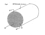
- FIG. 3a is a perspective view showing an example of the ceramic honeycomb structural body according to the invention
- FIG. 3b is a perspective view showing an example of the aggregate type honeycomb filter
- FIG. 4 is a perspective view of a integrated type honeycomb filter using porous ceramic members
- FIG. 5 is a schematic diagram of a catalyst reaction apparatus
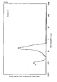
- FIG. 6a is a graph showing a relation between a pore size and a pore volume in a honeycomb unit according to the invention (Example 1)
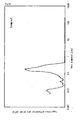
- FIG. 6b is a graph showing a relation between a pore size and a pore volume in a honeycomb unit according to the invention (Example 2)
- FIG. 6c is a graph showing a relation between a pore size and a pore volume in a honeycomb unit according to the invention (Example 3)
- FIG. 6d is a graph showing a relation between a pore size and a pore volume in a honeycomb unit according to the invention (Examples 4-7);
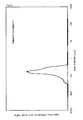
- FIG. 7a is a graph showing a relation between a pore size and a pore volume in a honeycomb unit according to a comparative example (Comparative Example 1)
- FIG. 7b is a graph showing a relation between a pore size and a pore volume in a honeycomb unit according to a comparative example (Comparative Example 2)
- FIG. 7c is a graph showing a relation between a pore size and a pore volume in a honeycomb unit according to a comparative example (Comparative Example 3).
- the inventors have examined the pore structure of the honeycomb structural body (sintered body) made of a porous ceramic used in the exhaust gas purification (conversion) apparatus and the like.
- the inventors have made studies on an example of changing the state of the pore size distribution in the structural body by adjusting the kind, particle size, compounding amount, compounding ratio of the starting materials, the firing temperature and the like.
- the inventors found that in the case of the ceramic honeycomb structural body, for example, used as a catalyst carrier, even if the porosity is the same, a great difference in the purification (conversion) efficiency is caused in accordance with the difference in the pore size distribution.
- the pore structure of the partition wall in the ceramic sintered body is good in the catalyst reactivity and effective in the purification (conversion) of the exhaust gas when one peak of the pore size distribution (maximum value) is existent in the range of 0.05-150 ⁇ m as the region of the first pore group and one or more peaks of the pore size distribution are existent in the range of 0.006-0.01 ⁇ m as the region of the second pore group, preferably two peaks are existent around 0.2 ⁇ m and around 0.009 ⁇ m.
- FIG. 2a is a representative schematic view of a ceramic member in which a peak of the pore size distribution is existent in each region of the first pore group and the second pore group, more particularly of a surface structure at a partition wall portion thereof.
- the surface structure shows such an example that pores having a large pore size D 1 of 0.05-150 ⁇ m and pores having a small pore size D 2 of 0.06-0.01 ⁇ m belonging to the second region of the pore size are existent sterically or in parallel on the same plane as shown in the figure.
- the invention is not limited to only the illustrated surface structure and may have a structure that pores having two or three different pore sizes are opened on the same plane.
- FIG. 2b and FIG. 2c are schematic views of the surface structure in the partition wall of the conventional structural body, in which FIG. 2b is an example in which only pores having a small pore size are existent and FIG. 2c is an example in which only pores having a large pore size are existent.
- the pore structure shown in FIG. 2a is an example of having plural kinds of pores having different pore sizes in the pores.
- the pore having the large pore size D 1 has a role of penetrating the exhaust gas in the inside of the partition wall through the pores to efficiently promote the reaction of the gas even in the inside of the partition wall to thereby improve the efficiency of the gas exchange before and after the reaction.
- the role of the pores having the small pore size D 2 belonging to the second pore group is considered to promote the reaction of the catalyst dispersed into and carried on the surfaces of the partition walls with the exhaust gas.
- molecules of the exhaust gas or the like easily penetrate into the inside of the wall of the catalyst carrier.
- the gas does not penetrate into the inside of the partition wall and the reaction with the catalyst in the inside of the wall becomes weak. Also, in the pore structure shown in FIG. 2c, the gas may penetrate into the inside of the wall, but the reaction with the catalyst cannot be promoted.
- the pore structure as a preferable embodiment of the invention can be formed, for example, by changing the particle size or composition of alumina or the like as the high specific area material constituting the catalyst carrier, and is effective as a means for improving the catalyst activity of the honeycomb structural body.
- the purification (conversion) property of the exhaust gas is particularly good.
- the ceramic honeycomb structural body shows the pore size distribution curve of the partition wall as shown in FIG. 1 which divides into the region of the first pore group consisting of pores having a pore size of 0.05-150 ⁇ m and the region of the second pore group consisting of pores having a pore size of 0.006-0.01 ⁇ m, if the pore structure has a peak (maximum value) in each of these regions, the purification (conversion) efficiency of the exhaust gas can be improved.
- the pore size distribution of the partition wall (cell wall) is adjusted to have a peak even in the region of the second pore group (0.006-0.01 ⁇ m)
- the whole of the partition wall renders into a high specific surface area, so that the particles of the catalyst metal can be made small and the dispersivility can be increased.
- the contact ratio of the exhaust gas with the catalyst metal and/or NOx absorption material can be increased to improve the purification (conversion) efficiency of the exhaust gas.
- the surface of the partition wall can ensure a high reactivity.
- the pore size of each of the pores is small, it is difficult to sufficiently penetrate the gas into the inside of the partition wall in the thickness direction and it is considered that the catalytic reaction may hardly occur in the inside of the partition wall.
- the pore structure of the partition wall is rendered to have a peak in the pore size distribution of the first pore group (0.05-150 ⁇ m).
- the gas is easy to deeply penetrate into the partition wall in the thickness direction and hence the purification (conversion) reaction of the gas occurs even in the inside of the partition wall, which brings about the improvement of the reactivity as a whole.
- the pore size distribution of the pores belonging to the first pore group is constructed such that one or more peaks are existent in a range of 0.05-1.0 ⁇ m.
- the partition wall has such a structure, it is considered that the gas easily penetrates into the interior of the partition wall.
- the thickness of the partition wall is about 0.05-0.35 mm, preferably about 0.10-0.30 mm, more preferably about 0.15-0.25 mm in connection with the pore structure.
- the wall thickness is not more than 0.35 mm, it can be expected that the contact area to the exhaust gas easily penetrates into the inside of the partition wall to improve the catalytic performance. While, when the thickness is less than 0.05 mm, there is a fear that the strength lowers.
- pore size distribution curve is continuous when the pore diameter of the pores in the first pore group is within a range of 0.01-1.0 ⁇ m and/or the value of the logarithmic differential pore volume is positive in the region between peak values producing in the first and second pore groups. That is, as shown in the graph of the accumulated pore volume (cc/g) (shown by dotted lines) in FIG. 1, it is desirable that this curve rises continuously. At this state, it is considered that the purification (conversion) for a wide variety of gases is possible regardless of the easiness of absorption depending on the size of the molecule or the like of the exhaust gas components discharged from the automobile.
- the ceramic honeycomb structural body according to a preferable embodiment of the invention is formed by using one unit or a combination of plural units when a porous ceramic member of a pillar-shaped honeycomb structure comprising a plurality of through-holes (cells) arranged side by side through the partition walls (hereinafter simply abbreviated as "honeycomb unit”) is a constitutional unit. That is, the ceramic honeycomb structural body simply called in the invention includes not only the structural body formed by combining a plurality of honeycomb units through a sealing material layer (hereinafter referred to as "an aggregate type honeycomb structural body), but also the structural body comprising a single honeycomb unit as a whole (hereinafter referred to as "integrated type honeycomb structural body").
- a sealing material layer for sealing the adjacent honeycomb units is necessary, and a coating material layer may be arranged on the outermost portion.
- the sealing material layer at least interposed between the mutual honeycomb units is useless.
- FIG. 3a is a perspective view partly omitted of an example of the porous ceramic member (honeycomb unit 11) used in the aggregate type honeycomb structural body as an example of the ceramic honeycomb structural body according to the invention.
- FIG. 3b is a perspective view of an exhaust gas purification (conversion) apparatus comprising the aggregate type honeycomb structural body formed by combining a plurality of the honeycomb units shown in FIG. 3a.
- the honeycomb unit 11 has a plurality of through-holes (cells) 12 as a gas path and partition walls (cell walls) 13.
- the honeycomb unit 11 is preferable to have a shape of easily bonding the honeycomb units 11 with each other, and the cross-sectional shape perpendicular to the through-hole may be square, rectangular, hexagonal, fan-shape, or the combination thereof.
- the aggregate type honeycomb structural body 10 is a block formed by bonding a plurality of the honeycomb units 11 through a sealing material layer 14.
- a coating material layer 16 for preventing the leakage of the exhaust gas or ensuring the strength may be formed on the outer periphery of the block.
- One of the features of the aggregate type honeycomb structural body lies in that the strength against the thermal shock or vibration is high. Because, it is guessed that even when the temperature distribution is produced in the honeycomb structural body due to a rapid temperature change or the like, the temperature difference in the structural body can be controlled to a small value and the thermal shock can be mitigated through the sealing material layer 14. Particularly, even when cracks are generated in the honeycomb unit, for example, due to the thermal stress or the like, the sealing material layer 14 is effective to prevent the progress of such cracks generated in the unit to the whole of the honeycomb structural body. Further, since it plays the role as a part of the main honeycomb structural body (frame), it is considered to be effective in maintaining the shape as a honeycomb structural body and the function as a catalyst carrier.
- the honeycomb unit 11 constituting the aggregate type honeycomb structural body is made of a porous ceramic and the area of the cross section perpendicular to the through-hole 12 (the size of the unit itself, hereinafter referred to as "cross sectional area" simply) is about 5-50 cm 2 .
- the cross sectional area is less than about 5 cm 2 , the cross sectional area of the sealing material layer 14 bonding the plural honeycomb units becomes large to increase the pressure loss, and also the specific surface area supporting the catalyst becomes relatively small, so that the catalyst component cannot be efficiently dispersed.
- the cross sectional area exceeds about 50 cm 2 , the size of the honeycomb unit becomes too large and the thermal stress generated in each of the honeycomb units cannot be sufficiently restrained.
- the cross sectional area is preferably about 6-40 cm 2 , more preferably about 8-30 cm 2 .
- the honeycomb unit 11 having a cross sectional area of the above range is practical, because the pressure loss can be kept small while maintaining the specific surface area large and also a sufficient strength against the thermal shock (thermal stress) and a high resistance to vibration or a high durability are indicated.
- cross sectional area of honeycomb unit means a cross sectional area of a honeycomb unit as a basic unit constituting the honeycomb structural body when the honeycomb structural body comprises a plurality of honeycomb units each having different cross sectional areas, and generally means a largest cross sectional area.
- the ratio of the total cross sectional area of the honeycomb units to the cross sectional area of the honeycomb structural body is preferably not less than about 85%, more preferably not less than 90%.
- the ratio of the honeycomb units is less than about 85%, the ratio of the honeycomb units occupied in the total cross sectional area decreases, so that the specific surface area supporting the catalyst becomes relatively small and the cross sectional area of the sealing material layer 14 becomes relatively large, thereby the pressure loss becomes large.
- the ratio is not less than 90%, the pressure loss can be further reduced.
- ceramic particles having a high specific surface area as a material constituting the honeycomb unit itself.
- one or more particles selected from alumina, silica, zirconia, titania, ceria, mullite and zeolite can be used, and among them, the use of alumina is preferable.
- the porosity of the honeycomb unit is about 20-80%, preferably about 50-70%. When the porosity is less than about 20%, the gas may not be penetrated into the inside of the wall, while when the porosity exceeds about 80%, the strength of the ceramic member is lowered to easily break.
- the porosity can be measured by the conventionally known methods such as a mercury penetration method, Archimedes' method, a measurement using a scanning electron microscope (SEM) and the like.
- honeycomb structural body may be constructed with a porous honeycomb ceramic member(s) (honeycomb unit) produced by mixing an inorganic material of a first embodiment (an inorganic material having a large specific surface area) with a different kind of material such as an inorganic material of a second embodiment (hereinafter referred to as "high specific surface area honeycomb unit").
- the high specific surface area honeycomb unit is preferable to contain at least ceramic particles and an inorganic binder, or ceramic particles, an inorganic reinforcement material and an inorganic binder.
- the inorganic particles can be bonded (adhered) through the inorganic binder.
- the specific surface area per high unit volume of the honeycomb unit becomes large and also it is effective to provide a honeycomb structural body having a strength for stably maintaining the honeycomb shape.
- the honeycomb unit can be provided with a higher strength by adding the inorganic reinforcement material, whereby a honeycomb structural body having a high specific surface area per unit volume can be obtained.
- the honeycomb structural body comprising such a honeycomb unit(s) can carry a catalyst component widely dispersed over the structural body to ensure a high specific surface area. Also, even if the ceramic particles of the unit are not sufficiently sintered, it is possible to maintain the shape under a situation subjected to the thermal shock or vibration (e.g., in the case of mounting on the vehicle).
- the inorganic material of the first embodiment used in the production of the high specific surface area honeycomb unit is an inorganic material having a predetermined aspect ratio (long side/short side) (high specific surface area particles), and as the inorganic material of the second embodiment is used an inorganic material having an aspect ratio larger than the predetermined aspect ratio.
- the strength of the honeycomb unit can be increased by adding the inorganic material of the second embodiment having the larger aspect ratio.
- the inorganic material of the second embodiment is preferable to have an aspect ratio of 2-1000, more preferably 5-800, further preferably 10-500. When the aspect ratio of the inorganic material of the second embodiment is less than 2, the contribution to the improvement of the strength in the honeycomb structural body is small.
- the inorganic material breaks at the shaping such as an extrusion molding to cause a scattering in the length, so that the contribution to the improvement of the strength in the honeycomb structural body becomes small.
- the aspect ratio of the inorganic material of the second embodiment has a distribution, the average value may be adopted.
- the inorganic material of the first embodiment may be ceramic particles having a high specific surface area and the inorganic material of the second embodiment may be inorganic fibers.
- the strength of the honeycomb unit can be increased by the inorganic fibers.
- the inorganic material of the first embodiment may be ceramic particles having a given particle size and the inorganic material of the second embodiment may be ceramic particles having a particle size larger than that of the inorganic material of the first embodiment.
- the strength of the honeycomb unit is increased by the ceramic particles having the larger particle size.
- the inorganic material of the second embodiment is preferable to have a particle size larger than that of the inorganic material of the first embodiment by 5 times or more, more preferably 10-30 times.
- the ceramic particles as the inorganic material of the second embodiment preferably have a particles size of about 10-60 ⁇ m, more preferably about 20-50 ⁇ m.
- the particle size is less than 10 ⁇ m, the strength of the honeycomb structural body cannot be sufficiently improved, while when it exceeds 60 ⁇ m, the clogging may easily occur in a molding at the shaping to deteriorate the formability.
- the average value thereof may be used.
- the ceramic particles for the inorganic material of the second embodiment may be selected from a different kind of the ceramic particles for the inorganic material of the first embodiment, or the same kind of the ceramic particles for the inorganic material of the first embodiment having a different shape (particle shape) or different properties (e.g., particles having a different crystal form and melting temperature).
- the magnification of the particle size of this material can increase the strength of the honeycomb structural body, so that the aspect ratio may be the same as that of the inorganic material of the first embodiment.
- the ceramic particles having a large specific surface area are desirable and there may be used, for example, one or more particles selected from alumina, silica, zirconia, titania, ceria, and mullite. Among them, alumina is particularly preferable.
- the inorganic material of the second embodiment is not particularly limited, but there may be used, for example, nitride ceramics such as aluminum nitride, silicon nitride, boron nitride, titanium nitride and the like; carbide ceramics such as silicon carbide, zirconium carbide, titanium carbide, tantalum carbide, tungsten carbide and the like; and oxide ceramics such as alumina, zirconia, cordierite, mullite, zirconia and the like.
- nitride ceramics such as aluminum nitride, silicon nitride, boron nitride, titanium nitride and the like
- carbide ceramics such as silicon carbide, zirconium carbide, titanium carbide, tantalum carbide, tungsten carbide and the like
- oxide ceramics such as alumina, zirconia, cordierite, mullite, zirconia and the like.
- inorganic fibers When inorganic fibers are used as the inorganic material of the first embodiment and the inorganic material of the second embodiment, there may be used, for example, ceramic fibers made of alumina, silica, silica-alumina, glass, potassium titanate, aluminum borate and the like; and whiskers made of alumina, silica, zirconia, titania, ceria, mullite, silicon carbide and the like as the inorganic fiber. They can be used alone or in a combination of two or more. Among the inorganic fibers, alumina fiber is desirable.
- the amount of the inorganic material of the first embodiment (ceramic particles or the like) compounded is about 30-97 mass%, preferably 30-90 mass%, more preferably 40-80 mass%, further preferably 50-75 mass%.
- the amount in the first embodiment is less than 30 mass%, the specific surface area as the honeycomb structural body becomes small and the catalyst component cannot be widely dispersed in the carrying of the catalyst compound.
- the amount of the inorganic material of the second embodiment (inorganic fibers or the like) compounded for contributing to the increase of the strength becomes small, and hence it is considered to lower the strength of the honeycomb structural body.
- the amount of the inorganic material of the second embodiment (inorganic fibers, whiskers or the like) compounded is about 3-70 mass%, preferably 3-50 mass%, more preferably 5-40 mass%, further preferably 8-30 mass%.
- the amount of the inorganic material of the second embodiment compounded is less than 3 mass%, the strength of the honeycomb structural body lowers, while when it exceeds 70 mass%, the amount of the inorganic material of the first embodiment compounded for contributing to the increase of the specific surface area becomes relatively small, and hence the specific surface area as the honeycomb structural body becomes small and the catalyst component cannot be sufficiently dispersed.
- An inorganic binder can be used in the production of the honeycomb unit. It is effective to provide a sufficient strength even if the firing temperature of the honeycomb unit is lowered.
- the inorganic binder may be used, for example, an inorganic sol, a clay-based binder and the like. Among them may be used, for example, one or more inorganic sols selected from alumina sol, silica sol, titania sol, water glass and the like as the inorganic sol.
- the clay-based binder may be used, for example, one or more clay-based binders selected from while clay, kaoline, montmorillonite, multi-chain structural clay (sepiolite, attapulgite) and the like.
- the amount of the inorganic binder compounded as a solid content is not more than 50 parts by mass, preferably 5-50 parts by mass, more preferably 10-40 parts by mass, further preferably 15-35 parts by mass based on 100 parts by mass of the total amount of the inorganic material of the first embodiment and the inorganic material of the second embodiment.
- the amount of the inorganic binder exceeds 50 parts by mass, it is considered that the formability becomes worse.
- the number of the through-holes formed in the honeycomb unit per unit cross sectional area is preferably about 15.5-186 holes/cm 2 (100-1200 cpsi), more preferably 46.5-170.5 cm 2 (300-1100 cpsi), further preferably 62.0-155 holes/cm 2 (400-1000 cpsi).
- the number of the through-holes is less than 15.5 holes/cm 2 , the area of the walls contacting with the exhaust gas in the porous honeycomb unit becomes small, while when it exceeds 186 holes/cm 2 the pressure loss increases and it becomes difficult to produce the honeycomb unit.
- the cross sectional shape of the through-hole formed in the honeycomb unit is preferable to be approximately triangle or hexagon. Because, it is considered to enhance the strength of the honeycomb unit to increase the strength of the ceramic honeycomb structural body (e.g., isostatic strength or the like) without lowering the pressure loss, the exhaust gas purification (conversion) capability and the like.
- the cross sectional shape of the through-hole is triangle
- the through-holes 12 having the triangle cross section are arranged opposite to each other alternately above and below or the apexes of the 4 through-holes having the triangle cross section are arranged opposite to each other to form a square.
- a through-hole having a hexagonal cross section may be formed.
- the ceramic honeycomb structural body suitable for the invention is a carrier for carrying a catalyst component on the surfaces of the partition walls of the honeycomb unit or on the surfaces of the ceramic particles constituting the partition wall.
- the ceramic honeycomb structural body is a honeycomb catalyst.
- the catalyst compound carried in the structural body may be used, for example, a noble metal, an alkaline metal compound, an alkaline earth metal compound, an oxide and the like.
- the noble metal may be used, for example, one or more selected from platinum, palladium and rhodium.
- the alkaline metal compound may be used, for example, compounds of one or more selected from potassium, sodium and the like.
- the alkaline earth metal compound may be used, for example, a compound of barium or the like.
- the oxide may be used perovskite (La 0.75 K 0.25 MnO 3 et al), CeO 2 or the like.
- the honeycomb catalyst can be used, for example, as a so-called three-way catalyst, or NOx absorption catalyst for the purification (conversion) of the exhaust gas discharged from automobiles.
- the catalyst component can be carried after the production of the ceramic honeycomb structural body or at the stage of the ceramic particles as the starting material. The carrying of the catalyst component can be conducted, for example, by the impregnation method or the like.
- a starting paste mainly composed of the aforementioned starting materials (the inorganic material of the first embodiment, the inorganic material of the second embodiment, the inorganic binder and the like) is extrusion-molded to prepare a green shaped body of a honeycomb unit.
- an organic binder a dispersion medium and a shaping assistance in accordance with the shaping property.
- the organic binder can be used, for example, one or more organic binders selected from methylcellulose, carboxymethyl cellulose, hydroxyethyl cellulose, polyethylene glycol, phenol resin and epoxy resin.
- the amount of the organic binder compounded is preferably about 1-10 mass% based on 100 parts by weight in total of the amounts of the inorganic material of the first embodiment, the inorganic material of the second embodiment and the inorganic binder.
- the dispersion medium may be used, for example, water, organic solvent (benzene or the like), alcohol (methanol or the like) and the like.
- the shaping assistant may be used, for example, ethylene glycol, dextrin, aliphatic acid, aliphatic acid soap, polyvinyl alcohol and the like.
- the starting paste may be mixed by a mixer, an attritor or the like, and it is preferable to well mix and knead by means of a kneader or the like.
- a mixer an attritor or the like
- the method for shaping the starting paste it is preferable to integrally shape into a honeycomb form having through-holes, for example, by means of the extrusion molding.
- the resulting green shaped body is dried.
- a drying machine used for the drying may be used, for example, a microwave drying machine, a hot-air drying machine, a dielectric drying machine, a reduce-pressure drying machine, a vacuum drying machine, a freeze drying machine and the like.
- the thus dried shaped body is preferably subjected to the degreasing.
- the condition for degreasing may be properly selected according to the kind or amount of the organic matter contained in the shaped body, but a condition of about 400°C x 2 hours is preferable.
- the thus dried shaped body is preferably fired by continuously raising the temperature. The firing is preferably conducted by heating, for example, at a temperature of about 600-1200°C.
- the firing temperature is preferable to be about 1000-2200°C.
- a fired honeycomb unit made of a porous ceramic having a plurality of through-holes can be obtained through these steps.
- the pore size distribution of the thus obtained honeycomb unit is adjusted according to the particle size and the particle size distribution of the material, and the condition of the addition of the slurry.
- a sealing material paste as a sealing material layer is applied onto the surfaces of the obtained porous ceramic honeycomb units and the adjoining honeycomb units are sequentially joined and adhered with each other, which is then dried and fixed to prepare a joint body of the honeycomb units having a given size.
- the sealing material for joining the units with each other may be used, for example, a mixture of an inorganic binder and ceramic particles, a mixture of an inorganic binder and inorganic fibers, a mixture of an inorganic binder, ceramic particles and inorganic fibers and the like.
- the sealing material may be added with an organic binder.
- the organic binder may be used, for example, one or more selected from polyvinyl alcohol, methylcellulose, ethylcellulose, carboxymethyl cellulose and the like.
- the inorganic binder used for the sealing material may be used, for example, silica sol, alumina sol and the like. They may be used alone or in a combination of two or more.
- silica sol is desirable.
- the inorganic fiber used for the sealing material may be used, for example, ceramic fibers of silica-alumina, mullite, alumina silica and the like. They may be used alone or in a combination of two or more.
- silica-alumina fiber is desirable.
- the inorganic particles used for the sealing material may be used, for example, carbides, nitrides and the like.
- inorganic powder made of silicon carbide, silicon nitride, boron nitride and the like, a whisker or the like may be used. They may be used alone or in a combination of two or more.
- silicon carbide being excellent in the thermal conductivity is desirable.
- the sealing material layer 14 interposed between the mutual honeycomb units may be dense or porous, or enables to flow the exhaust gas into the inside.
- the sealing material layer 16 (coating layer) formed on the outer peripheral portion of the aggregate type honeycomb structural body is desirably made of a dense body. Because, in the case of the sealing material layer 16, when the aggregate type honeycomb structural body according to the invention is installed in the exhaust gas path of the internal engine, it is necessary to prevent the leakage of the exhaust gas from the outer peripheral portion of the honeycomb structural body.
- the sealing material layer 14 interposed between the adjoining honeycomb units for bonding and adhering them is preferable to have a thickness of about 0.5-2 mm.
- the thickness of the sealing material layer 14 is less than 0.5 mm, the sufficient adhesion strength is not obtained.
- the sealing material layer 14 is not a portion functioning as a catalyst carrier, when the thickness exceeds 2 mm, the specific surface area per unit volume of the ceramic honeycomb structural body is relatively lowered and the dispersion efficiency of the catalyst component is decreased.
- the thickness of the sealing material layer 14 exceeds 2 mm, the pressure loss becomes large.
- the number of the honeycomb units joined may be properly determined in accordance with the size of the honeycomb structural body used as a honeycomb catalyst.
- the joint body formed by joining the honeycomb units through the sealing material may be properly cut and polished in accordance with the size of the ceramic honeycomb structural body to form a product.
- a coating material Onto the outer peripheral portion (side surface) of the ceramic honeycomb structural body may be applied a coating material, which may be dried and fixed to form a coating material layer, that is, a sealing material layer 16.
- the sealing material layer 16 functions effectively in protecting the outer peripheral portion of the structural body and increasing its strength.
- the coating material may be made of the same material as the sealing material layer 14, or may be a different material and the compounding ratio may be the same or different.
- the thickness of the coating material layer 16 is preferably about 0.1-2 mm.
- the aggregate type honeycomb structural body made by combining the plural honeycomb units after the joining through the sealing material layer 14 (provided that if a sealing material layer (coating material layer 16) is formed, after the formation of the coating material layer) is preferable to be calcined.
- an organic binder is contained in the sealing material or coating material, it can be degreased and removed through this treatment.
- the calcination conditions may be determined in accordance with the kind or amount of the organic matter, but they are preferable to be about 700°C x 2 hours.
- the ceramic honeycomb structural body obtained by the calcination does not discharge the contaminated exhaust gas in use since the organic binder included in the ceramic honeycomb structural body is burnt.
- FIG. 3b shows a conceptual view of a cylindrical aggregate type honeycomb structural body 10 formed by joining a plurality of rectangular porous honeycomb units 11 having a square cross section.
- a plurality of the honeycomb units 11 are joined through the sealing material layer 14 and shaped as its outer periphery into a cylindrical form by cutting, and thereafter a sealing material (coating material) is applied onto the outer peripheral portion thereof, i.e. the outer peripheral surface not opening a though-hole 12 to form a sealing material layer 16.
- the cutting step may be omitted when honeycomb units 11 having, for example, a fan-shaped form or a square in their section are shaped and joined so as to previously form a cylindrical ceramic honeycomb structural body.
- FIG. 4 is a perspective view showing a integrated type honeycomb structural body as another example of the ceramic honeycomb structural body according to the invention.
- the integrated type honeycomb structural body 20 is a columnar block formed by arranging a plurality of through-holes 21 side by side in the longitudinal direction through partition walls 23.
- the integrated type honeycomb structural body is constructed in the same way as the aggregate type honeycomb structural body 10 except that the block has a integrated structure formed by the sintering.
- the size of the block 25 is properly determined in accordance with the displacement of the internal engines, the size of the exhaust gas path and the like.
- the shape of the block 25 may be pillar-shaped, which includes, for example, cylindrical-shaped, elliptic-cylindrical shaped, prismatic-shaped and so on.
- the test is carried out in order to confirm the actions and effects when a honeycomb unit made of fiber-reinforced alumina is produced by changing particle size and particle distribution and a catalyst coating layer made of platinum-containing alumina is formed on the surface thereof (the surface of the partition wall).
- Table 1 shows details of Examples 1-7 and Comparative Examples 1-3.
- the production method of the honeycomb unit is as follows.
- ⁇ -alumina particles a mixture of primary particles and secondary particles compounded as described in Table 1 provided that an average particle size is 2 ⁇ m
- 10 mass% of silica-alumina fibers an average fiber diameter: 10 ⁇ m, an average fiber length: 100 ⁇ m, an aspect ratio: 10
- 50 mass% of silica-sol solid concentration: 30 mass%)
- 6 parts by weight of methylcellulose as an organic binder and a small amount of plasticizer and lubricant are added to 100 parts by weight of the resulting mixture and further mixed and kneaded to prepare a mixed composition.
- the mixed composition is extrusion molded through an extruder to obtain a green shaped body as shown in FIG. 3a.
- the green shaped body is sufficiently dried by means of a microwave drying machine and a hot-air drying machine and degreased by holding at 400°C for 2 hours and then fired by holding at 800°C for 2 hours to obtain a honeycomb unit 11 made of porous fiber-reinforced alumina having a square columnar shape (34.3 mm x 34.3 mm x 150 mm), a cell density of 93 cells/cm 2 (600 cpsi) and a square (quadrilateral) cell form.
- a heat-resistant paste for a sealing material is prepared by mixing 29 mass% of ⁇ -alumina particles, 7 mass% of silica-alumina fibers (having an average fiber diameter of 10 ⁇ m and an average fiber length of 100 ⁇ m), 4 mass% of silica sol (solid concentration of 30 mass%), 50 mass% of carboxymethyl cellulose and 25 mass% of water.
- the paste for the sealing material is applied on the side surfaces of the honeycomb units 11 to join them with each other. That is, the paste for the sealing material is applied on the outer surface 13 of the honeycomb unit 11 in a thickness of 1 mm to form a sealing material layer 14 and a plurality of honeycomb units 11 are joined with each other through the sealing material layer 14.
- a joint body as an aggregate type honeycomb unit is thus produced and cut in a cylindrical shape using a diamond cutter so that the front faces are approximately symmetric about a point, and then the paste for the sealing material is applied on the outer surface of the side surface portion not having through-holes in a thickness of 0.5 mm to form a sealing material layer 16 comprising a coating layer on the outer surface.
- the obtained joint body is dried at 120°C and held at 700°C for 2 hours to conduct the degreasing of the sealing material layer 14 and the sealing material layer (coating layer) 16, whereby a cylindrical aggregate type honeycomb structural body 10 (diameter of 143.8 mm x height of 150 mm) is obtained. It is immersed in a solution of platinum nitrite to carry a catalyst component thereon so that the weight of platinum per unit volume of the aggregate type honeycomb structural body 10 is adjusted to 2 g/L, which is held at 600°C for 1 hour to obtain a honeycomb catalyst.
- the pore size is measured through a mercury penetration method (according to JISR1655:2003).
- the pore size of the obtained sample is measured using a micromeritics automatic porosimeter, Auto Pore III 9405, made by Shimadzu Corporation.
- the measured range is 0.006 ⁇ m-500 ⁇ m, in which the measurement in the range of 100 ⁇ m-500 ⁇ m is conducted every a pressure of 0.1 psia and the measurement in the range of 0.006 ⁇ m-100 ⁇ m is conducted every a pressure of 0.25 psia.
- the numerical values are shown in Table 2.
- the light-off temperature means a reaction temperature indicating a purification (conversion) efficiency of 50 % when the purification (conversion) efficiency is a ratio of decreasing a concentration of specific components included in the exhaust gas by the catalyst.
- the light-off temperature is low, the energy required for the purification (conversion) becomes small. That is, it can be said that a honeycomb catalyst having a low light-off temperature has an excellent catalytic performance. Therefore, the light-off temperature can be used as an indication showing a catalytic performance of the honeycomb catalyst.
- the catalytic reaction apparatus 30 comprises a feed portion 31 of a dilution gas comprising air and nitrogen, a flow path 32 flowing the dilution gas to the honeycomb structural body, a humidifier 33 humidifying the dilution gas, a heater 34 heating the dilution gas, a gas mixer 35 mixing the heated dilution gas with an exhaust gas component to prepare a reaction gas, a sample holder 36 holding the honeycomb structural body in an air-tight condition, a gas sampler 37 sampling the reaction gas before the contact with the ceramic honeycomb structural body, a gas sampler 38 sampling the reaction gas after the contact with the ceramic honeycomb structural body and a gas analyzer 39 analyzing the concentration of the specific gas components included in the reaction gas.
- the honeycomb structural body is set in the sample holder 36 and air and nitrogen are flowed from the dilution gas feed portion 31 to the flow path 32 at a given flow rate. Then, the dilution gas is humidified through the humidifier 33 and the temperature of the dilution gas is adjusted through the heater 34. Next, the exhaust gas component is flown into the flown dilution gas from an upstream of the gas mixer 35 and mixed in the gas mixer 35 to prepare a reaction gas having a given concentration. Then, the thus prepared reaction gas is contacted with the honeycomb catalyst to conduct the purification (conversion) of the reaction gas.
- the temperature of the heater 34 is properly changed to measure a temperature of the reaction gas inside the honeycomb catalyst at each temperature of the heater 34 through a thermocouple not shown.
- the concentration of the reaction gas sampled by the gas samplers 37 and 38 is measured through the gas analyzer 39.
- a honeycomb structural body having a shape of 34.3 mm square x 150 mm as an Example or a Comparative Example.
- the catalytic reaction is conducted under conditions that a flow rate of the reaction gas is 131 (1/min), and the exhaust gas component comprises oxygen, carbon monoxide, sulfur dioxide, carbon hydride, nitrogen monoxide, steam and nitrogen, and an oxygen concentration in the reaction gas is 13%, and a carbon monoxide concentration is 300 ppm, and a sulfur dioxide concentration is 8 ppm and a hydrocarbon concentration is 200 ppm-C based on the amount of carbon, and a nitrogen monoxide concentration is 160 ppm, and a small amount of a humidification is added.
- the reaction temperature is changed between 50-400°C by changing the temperature of the heater 34 every 10°C, during which the concentrations of carbon monoxide and hydrocarbon among the components included in the reaction gas to be purified are measured by the gas analyzer 39.
- Example 1 State of pore size distribution ( ⁇ m) Wall thickness (mm) Light-off temperature CO (°C) Light-off temperature HC (°C)
- Example 1 0 . 006-0.01 ⁇ m peak Absence (discontinuous) 0.05-0.5 ⁇ m peak Absence (discontinuous) 0.2 107 154
- Example 2 0.006-0.01 ⁇ m peak 0 .02-0.05 ⁇ m peak 0.05-0.5 ⁇ m peak Absence (discontinuous) 0.2 106 149
- Example 3 0.006-0.01 ⁇ m peak 0 .02-0.
- the ceramic honeycomb structural body when the partition walls are divided into a region of the first pore group of pores having a pore size of 0.05 to 150 ⁇ m and a region of the second pore group of pores having a pore size of 0.006 to 0.01 ⁇ m, the ceramic honeycomb structural body has a pore size distribution that one or more peaks (maximum value) of the pore size distribution are existent in each of the regions, so that it can be a honeycomb structural body for the purification (conversion) of the exhaust gas having a high purification (conversion) efficiency of the harmful exhaust gas.
- the invention can be used not only as an exhaust gas purification (conversion) apparatus of internal combustion engine but also as a purification (conversion) apparatus or filter of an exhaust gas discharged from a boiler, a heating furnace, a gas turbine, or various industrial processes.
- the ceramic honeycomb structural body according to the invention is used as a catalyst carrier for the purification (conversion) of the exhaust gas in the above various apparatuses, but also as an exhaust gas purification (conversion) apparatus of diesel engines.
- the this honeycomb structural body can be used not only for the above applications, but also applications used without carrying the catalyst component (e.g., an absorbent absorbing a gas component or fluid component and the like).
Landscapes
- Chemical & Material Sciences (AREA)
- Engineering & Computer Science (AREA)
- Chemical Kinetics & Catalysis (AREA)
- Materials Engineering (AREA)
- Organic Chemistry (AREA)
- Ceramic Engineering (AREA)
- Health & Medical Sciences (AREA)
- Combustion & Propulsion (AREA)
- Toxicology (AREA)
- Mechanical Engineering (AREA)
- General Engineering & Computer Science (AREA)
- Structural Engineering (AREA)
- Biomedical Technology (AREA)
- Environmental & Geological Engineering (AREA)
- Analytical Chemistry (AREA)
- General Chemical & Material Sciences (AREA)
- Oil, Petroleum & Natural Gas (AREA)
- Catalysts (AREA)
- Exhaust Gas Treatment By Means Of Catalyst (AREA)
- Exhaust Gas After Treatment (AREA)
- Filtering Materials (AREA)
- Filtering Of Dispersed Particles In Gases (AREA)
- Porous Artificial Stone Or Porous Ceramic Products (AREA)
- Ceramic Products (AREA)
- Compositions Of Oxide Ceramics (AREA)
Abstract
Description
- This application is an application claiming a priority right based on
Japanese Patent Application No. 2004-375815 filed on December 27, 2004 - This invention relates to a ceramic honeycomb structural body, and more particularly to a ceramic honeycomb structural body used for carrying a catalyst for the purification (conversion) of the exhaust gas discharged from internal combustion engines such as vehicles, boilers and the like.
- As the ceramic honeycomb structural body used for carrying a catalyst for the purification (conversion) of the exhaust gas from vehicles is mainly used an integrally structural product made from a low thermal expansive cordierite or the like. Such a ceramic honeycomb structural body is common to support a material having a high specific surface area such as an active alumina or the like, and a catalyst metal such as platinum or the like on its surface. Also, in engines used under excess oxygen conditions such as lean burn engine and diesel engine, NOx occlusion agent made from an alkaline earth metal such as Ba or the like for the NOx treatment is carried on the surface of the structural body.
- In order to further improve the purification (conversion) performance of the ceramic honeycomb structural body, it is effective to increase the contact efficiency between the exhaust gas and the noble metal catalyst or the NOx occlusion agent. For this end, it is important to carry the catalyst on the surface of the partition wall of the ceramic honeycomb structural body in a well-dispersed condition. (See
JP-A-H10-263416 - Also, as the ceramic honeycomb structural body, there is proposed a technique for improving the reactivity by adjusting the pore size distribution (See
JP-A-H03-68456 JP-A-H08-229412 JP-A-2001-187318 JP-A-2001-187320 JP-AH10-43588 - In the conventional ceramic honeycomb structural bodies, however, since the material having a high specific surface area (catalyst coating layer) is applied onto the surface of the partition wall or the pore size of the partition wall is adjusted, almost of the structural bodies are not still sufficient in the catalyst reactivity, so that further improvement is required. That is, when the high specific surface area material such as alumina or the like is used in the ceramic honeycomb structural body, there is a fear that the sintering is advanced due to the heat aging to lower the specific surface area. Also, there is a tendency that the catalyst metal carried such as platinum or the like aggregates to increase the particle size to thereby reduce the specific surface area. That is, in the conventional ceramic honeycomb structural body, it is necessary to increase the specific surface area at the initial stage in order to make the specific surface area high after the heat ageing (because it is used as a catalyst carrier).
- Also, in order to increase the gas purification (conversion) capability of the ceramic honeycomb structural bodies, it is effective to increase the contact efficiency among the exhaust gas and the noble metal catalyst and the NOx occlusion agent. That is, it is effective to increase the dispersion degree by reducing the particle size of the catalyst while increasing the specific surface area of the ceramic honeycomb structural body as a carrier. In this connection, in the conventional honeycomb structural body made of cordierite, the catalyst carrier was rendered into a high specific surface area by adjusting the shape and density of the through-holes, the wall thickness or the like in order to increase the contact efficiency with the exhaust gas catalyst. In the conventional ceramic honeycomb structural body, however, there is a problem that the catalyst cannot be sufficiently dispersed on the carrier and the purification (conversion) performance of the exhaust gas after the heat aging is poor.
- Besides, there are conventional honeycomb structural bodies in which a large amount of the catalyst is carried or the size of the catalyst carrier itself is enlarged. However, the structural body carried with the large amount of the catalyst is not preferable because a noble metal such as platinum or the like is expensive, while the size-enlarged structural body is not suitable when being arranged in the vehicle because the installation space is extremely limited.
- It is an object of the invention to propose a ceramic honeycomb structural body being excellent in the removal property of harmful gases such as HC, NOx and the like discharged from the internal combustion engine and in the catalyst reactivity.
- The invention lies in a ceramic honeycomb structural body comprising one porous ceramic member of a pillar-shaped honeycomb structure formed by arranging a plurality of through-holes as a gas path side by side through a partition wall, or a combination of the ceramic members, characterized in that the partition wall is made from a sintered body having a pore structure that in a pore size distribution curve in which an abscissa is a pore diameter (µm) and an ordinate is a logarithmic differential pore volume (cm3/g), when pores having a pore diameter of 0.05-150 µm are a first pore group and pores having a pore diameter of 0.006-0.01 µm are a second pore group, one or more peaks (maximum value) of the pore distribution are existent in each region of the first pore group and the second pore group.
- The followings are a preferable embodiment of the construction of the invention, but are not intended as limitations thereof.
- (1) The peak of the pore size distribution of pores in the region of the first pore group is existent within a pore size range of 0.05-1.0 µm; (2) The pore size distribution curve is continuous when the value of the logarithmic differential pore volume is positive within a pore size range of 0.01-1.0 µm; (3) The pore size distribution curve is continuous when the value of the logarithmic differential pore volume is positive in a range of the pore sizes between the peaks (maximum values) in the first pore group and the second pore group; (4) The partition wall has a thickness of 0.05-0.35 mm; (5) The ceramic member contains alumina as a main component; (6) When a plurality of the ceramic members are combined, a sealing material layer is interposed between the members; (7) In the ceramic member, a catalyst is applied onto the surface of the partition wall or onto each surface of the ceramic particles constituting the partition wall; and (8) The honeycomb structural body is used as an exhaust gas purification (conversion) apparatus in vehicles.
- FIG. 1 is a graph showing an example of a pore size distribution curve in the ceramic honeycomb structural body according to the invention;
- FIG. 2a is a cross-sectional view schematically showing an example of pores formed in the ceramic honeycomb structural body according to the invention, FIGS. 2b and 2c are cross sectional views schematically showing a state of conventional fine pores;
- FIG. 3a is a perspective view showing an example of the ceramic honeycomb structural body according to the invention, and FIG. 3b is a perspective view showing an example of the aggregate type honeycomb filter;
- FIG. 4 is a perspective view of a integrated type honeycomb filter using porous ceramic members;
- FIG. 5 is a schematic diagram of a catalyst reaction apparatus;
- FIG. 6a is a graph showing a relation between a pore size and a pore volume in a honeycomb unit according to the invention (Example 1), FIG. 6b is a graph showing a relation between a pore size and a pore volume in a honeycomb unit according to the invention (Example 2), FIG. 6c is a graph showing a relation between a pore size and a pore volume in a honeycomb unit according to the invention (Example 3), and FIG. 6d is a graph showing a relation between a pore size and a pore volume in a honeycomb unit according to the invention (Examples 4-7);
- FIG. 7a is a graph showing a relation between a pore size and a pore volume in a honeycomb unit according to a comparative example (Comparative Example 1), FIG. 7b is a graph showing a relation between a pore size and a pore volume in a honeycomb unit according to a comparative example (Comparative Example 2), and FIG. 7c is a graph showing a relation between a pore size and a pore volume in a honeycomb unit according to a comparative example (Comparative Example 3).
- The inventors have examined the pore structure of the honeycomb structural body (sintered body) made of a porous ceramic used in the exhaust gas purification (conversion) apparatus and the like. In the examination, the inventors have made studies on an example of changing the state of the pore size distribution in the structural body by adjusting the kind, particle size, compounding amount, compounding ratio of the starting materials, the firing temperature and the like. As a result, the inventors found that in the case of the ceramic honeycomb structural body, for example, used as a catalyst carrier, even if the porosity is the same, a great difference in the purification (conversion) efficiency is caused in accordance with the difference in the pore size distribution.
- That is, in the curve of pore size distribution measured by a mercury penetration method in which an abscissa is a pore diameter (µm) and an ordinate is a logarithmic differential pore volume (cm3/g) as shown in FIG. 1, the pore structure of the partition wall in the ceramic sintered body is good in the catalyst reactivity and effective in the purification (conversion) of the exhaust gas when one peak of the pore size distribution (maximum value) is existent in the range of 0.05-150 µm as the region of the first pore group and one or more peaks of the pore size distribution are existent in the range of 0.006-0.01 µm as the region of the second pore group, preferably two peaks are existent around 0.2 µm and around 0.009 µm.
- As to the mechanism causing such a phenomenon, the inventors have guessed as follows. FIG. 2a is a representative schematic view of a ceramic member in which a peak of the pore size distribution is existent in each region of the first pore group and the second pore group, more particularly of a surface structure at a partition wall portion thereof. The surface structure shows such an example that pores having a large pore size D1 of 0.05-150 µm and pores having a small pore size D2 of 0.06-0.01 µm belonging to the second region of the pore size are existent sterically or in parallel on the same plane as shown in the figure. The invention is not limited to only the illustrated surface structure and may have a structure that pores having two or three different pore sizes are opened on the same plane.
- FIG. 2b and FIG. 2c are schematic views of the surface structure in the partition wall of the conventional structural body, in which FIG. 2b is an example in which only pores having a small pore size are existent and FIG. 2c is an example in which only pores having a large pore size are existent.
- Among these illustrated examples, the pore structure shown in FIG. 2a is an example of having plural kinds of pores having different pore sizes in the pores. In this case, it is considered that the pore having the large pore size D1 has a role of penetrating the exhaust gas in the inside of the partition wall through the pores to efficiently promote the reaction of the gas even in the inside of the partition wall to thereby improve the efficiency of the gas exchange before and after the reaction. While, the role of the pores having the small pore size D2 belonging to the second pore group is considered to promote the reaction of the catalyst dispersed into and carried on the surfaces of the partition walls with the exhaust gas. As a result, in the pore structure suitable for the invention, molecules of the exhaust gas or the like easily penetrate into the inside of the wall of the catalyst carrier.
- In the pore structure shown in FIG. 2b, the gas does not penetrate into the inside of the partition wall and the reaction with the catalyst in the inside of the wall becomes weak. Also, in the pore structure shown in FIG. 2c, the gas may penetrate into the inside of the wall, but the reaction with the catalyst cannot be promoted.
- The pore structure as a preferable embodiment of the invention can be formed, for example, by changing the particle size or composition of alumina or the like as the high specific area material constituting the catalyst carrier, and is effective as a means for improving the catalyst activity of the honeycomb structural body. For example, in case of the ceramic honeycomb structural body having the pore structure of the pore size distribution curve as shown in FIG. 1 formed by changing the particle size of alumina constituting the catalyst carrier, the purification (conversion) property of the exhaust gas is particularly good.
- That is, when the ceramic honeycomb structural body shows the pore size distribution curve of the partition wall as shown in FIG. 1 which divides into the region of the first pore group consisting of pores having a pore size of 0.05-150 µm and the region of the second pore group consisting of pores having a pore size of 0.006-0.01 µm, if the pore structure has a peak (maximum value) in each of these regions, the purification (conversion) efficiency of the exhaust gas can be improved.
- In the ceramic honeycomb structural body having such a construction, when the pore size distribution of the partition wall (cell wall) is adjusted to have a peak even in the region of the second pore group (0.006-0.01 µm), the whole of the partition wall renders into a high specific surface area, so that the particles of the catalyst metal can be made small and the dispersivility can be increased. Hence, the contact ratio of the exhaust gas with the catalyst metal and/or NOx absorption material can be increased to improve the purification (conversion) efficiency of the exhaust gas.
- In this case, since the specific surface area becomes large, the surface of the partition wall can ensure a high reactivity. In the ceramic honeycomb structural body having such a pore size distribution, however, since the pore size of each of the pores is small, it is difficult to sufficiently penetrate the gas into the inside of the partition wall in the thickness direction and it is considered that the catalytic reaction may hardly occur in the inside of the partition wall.
- In a preferable embodiment of the invention, therefore, the pore structure of the partition wall is rendered to have a peak in the pore size distribution of the first pore group (0.05-150 µm). As a result, the gas is easy to deeply penetrate into the partition wall in the thickness direction and hence the purification (conversion) reaction of the gas occurs even in the inside of the partition wall, which brings about the improvement of the reactivity as a whole.
- In the invention, the pore size distribution of the pores belonging to the first pore group is constructed such that one or more peaks are existent in a range of 0.05-1.0 µm. When the partition wall has such a structure, it is considered that the gas easily penetrates into the interior of the partition wall.
- The thickness of the partition wall is about 0.05-0.35 mm, preferably about 0.10-0.30 mm, more preferably about 0.15-0.25 mm in connection with the pore structure. When the wall thickness is not more than 0.35 mm, it can be expected that the contact area to the exhaust gas easily penetrates into the inside of the partition wall to improve the catalytic performance. While, when the thickness is less than 0.05 mm, there is a fear that the strength lowers.
- In the ceramic honeycomb structural body, it is desirable that pore size distribution curve is continuous when the pore diameter of the pores in the first pore group is within a range of 0.01-1.0 µm and/or the value of the logarithmic differential pore volume is positive in the region between peak values producing in the first and second pore groups. That is, as shown in the graph of the accumulated pore volume (cc/g) (shown by dotted lines) in FIG. 1, it is desirable that this curve rises continuously. At this state, it is considered that the purification (conversion) for a wide variety of gases is possible regardless of the easiness of absorption depending on the size of the molecule or the like of the exhaust gas components discharged from the automobile.
- The ceramic honeycomb structural body according to a preferable embodiment of the invention is formed by using one unit or a combination of plural units when a porous ceramic member of a pillar-shaped honeycomb structure comprising a plurality of through-holes (cells) arranged side by side through the partition walls (hereinafter simply abbreviated as "honeycomb unit") is a constitutional unit. That is, the ceramic honeycomb structural body simply called in the invention includes not only the structural body formed by combining a plurality of honeycomb units through a sealing material layer (hereinafter referred to as "an aggregate type honeycomb structural body), but also the structural body comprising a single honeycomb unit as a whole (hereinafter referred to as "integrated type honeycomb structural body").
- In the aggregate type honeycomb structural body, a sealing material layer for sealing the adjacent honeycomb units is necessary, and a coating material layer may be arranged on the outermost portion. However, since the integrated type honeycomb structural body consists of a single honeycomb unit, the sealing material layer at least interposed between the mutual honeycomb units is useless.
- FIG. 3a is a perspective view partly omitted of an example of the porous ceramic member (honeycomb unit 11) used in the aggregate type honeycomb structural body as an example of the ceramic honeycomb structural body according to the invention. FIG. 3b is a perspective view of an exhaust gas purification (conversion) apparatus comprising the aggregate type honeycomb structural body formed by combining a plurality of the honeycomb units shown in FIG. 3a. In the aggregate type honeycomb structural body, the
honeycomb unit 11 has a plurality of through-holes (cells) 12 as a gas path and partition walls (cell walls) 13. Thehoneycomb unit 11 is preferable to have a shape of easily bonding thehoneycomb units 11 with each other, and the cross-sectional shape perpendicular to the through-hole may be square, rectangular, hexagonal, fan-shape, or the combination thereof. - As shown in FIG. 3b, the aggregate type honeycomb
structural body 10 is a block formed by bonding a plurality of thehoneycomb units 11 through a sealingmaterial layer 14. Preferably, acoating material layer 16 for preventing the leakage of the exhaust gas or ensuring the strength may be formed on the outer periphery of the block. - One of the features of the aggregate type honeycomb structural body lies in that the strength against the thermal shock or vibration is high. Because, it is guessed that even when the temperature distribution is produced in the honeycomb structural body due to a rapid temperature change or the like, the temperature difference in the structural body can be controlled to a small value and the thermal shock can be mitigated through the sealing
material layer 14. Particularly, even when cracks are generated in the honeycomb unit, for example, due to the thermal stress or the like, the sealingmaterial layer 14 is effective to prevent the progress of such cracks generated in the unit to the whole of the honeycomb structural body. Further, since it plays the role as a part of the main honeycomb structural body (frame), it is considered to be effective in maintaining the shape as a honeycomb structural body and the function as a catalyst carrier. - It is preferable that the
honeycomb unit 11 constituting the aggregate type honeycomb structural body is made of a porous ceramic and the area of the cross section perpendicular to the through-hole 12 (the size of the unit itself, hereinafter referred to as "cross sectional area" simply) is about 5-50 cm2. When the cross sectional area is less than about 5 cm2, the cross sectional area of the sealingmaterial layer 14 bonding the plural honeycomb units becomes large to increase the pressure loss, and also the specific surface area supporting the catalyst becomes relatively small, so that the catalyst component cannot be efficiently dispersed. While, when the cross sectional area exceeds about 50 cm2, the size of the honeycomb unit becomes too large and the thermal stress generated in each of the honeycomb units cannot be sufficiently restrained. Moreover, the cross sectional area is preferably about 6-40 cm2, more preferably about 8-30 cm2. - Moreover, the
honeycomb unit 11 having a cross sectional area of the above range is practical, because the pressure loss can be kept small while maintaining the specific surface area large and also a sufficient strength against the thermal shock (thermal stress) and a high resistance to vibration or a high durability are indicated. - The term "cross sectional area of honeycomb unit" used herein means a cross sectional area of a honeycomb unit as a basic unit constituting the honeycomb structural body when the honeycomb structural body comprises a plurality of honeycomb units each having different cross sectional areas, and generally means a largest cross sectional area. Also, the ratio of the total cross sectional area of the honeycomb units to the cross sectional area of the honeycomb structural body is preferably not less than about 85%, more preferably not less than 90%. When the ratio of the honeycomb units is less than about 85%, the ratio of the honeycomb units occupied in the total cross sectional area decreases, so that the specific surface area supporting the catalyst becomes relatively small and the cross sectional area of the sealing
material layer 14 becomes relatively large, thereby the pressure loss becomes large. Also, when the ratio is not less than 90%, the pressure loss can be further reduced. - In the ceramic honeycomb structural body, it is preferable to use ceramic particles having a high specific surface area as a material constituting the honeycomb unit itself. For example, one or more particles selected from alumina, silica, zirconia, titania, ceria, mullite and zeolite can be used, and among them, the use of alumina is preferable.
- The porosity of the honeycomb unit is about 20-80%, preferably about 50-70%. When the porosity is less than about 20%, the gas may not be penetrated into the inside of the wall, while when the porosity exceeds about 80%, the strength of the ceramic member is lowered to easily break.
- The porosity can be measured by the conventionally known methods such as a mercury penetration method, Archimedes' method, a measurement using a scanning electron microscope (SEM) and the like.
- The above-mentioned honeycomb structural body may be constructed with a porous honeycomb ceramic member(s) (honeycomb unit) produced by mixing an inorganic material of a first embodiment (an inorganic material having a large specific surface area) with a different kind of material such as an inorganic material of a second embodiment (hereinafter referred to as "high specific surface area honeycomb unit").
- The high specific surface area honeycomb unit is preferable to contain at least ceramic particles and an inorganic binder, or ceramic particles, an inorganic reinforcement material and an inorganic binder.
- In such a honeycomb unit, the inorganic particles can be bonded (adhered) through the inorganic binder. In this case, when the inorganic particles are composed of particles having a high specific surface area, the specific surface area per high unit volume of the honeycomb unit becomes large and also it is effective to provide a honeycomb structural body having a strength for stably maintaining the honeycomb shape.
- Further, the honeycomb unit can be provided with a higher strength by adding the inorganic reinforcement material, whereby a honeycomb structural body having a high specific surface area per unit volume can be obtained.
- As a result, the honeycomb structural body comprising such a honeycomb unit(s) can carry a catalyst component widely dispersed over the structural body to ensure a high specific surface area. Also, even if the ceramic particles of the unit are not sufficiently sintered, it is possible to maintain the shape under a situation subjected to the thermal shock or vibration (e.g., in the case of mounting on the vehicle).
- The inorganic material of the first embodiment used in the production of the high specific surface area honeycomb unit is an inorganic material having a predetermined aspect ratio (long side/short side) (high specific surface area particles), and as the inorganic material of the second embodiment is used an inorganic material having an aspect ratio larger than the predetermined aspect ratio. In the honeycomb unit having such a material composition, the strength of the honeycomb unit can be increased by adding the inorganic material of the second embodiment having the larger aspect ratio. The inorganic material of the second embodiment is preferable to have an aspect ratio of 2-1000, more preferably 5-800, further preferably 10-500. When the aspect ratio of the inorganic material of the second embodiment is less than 2, the contribution to the improvement of the strength in the honeycomb structural body is small. While, when it exceeds 1000, the clogging may easily occur in a mold at the shaping and the formability may become worse. Also, the inorganic material breaks at the shaping such as an extrusion molding to cause a scattering in the length, so that the contribution to the improvement of the strength in the honeycomb structural body becomes small. When the aspect ratio of the inorganic material of the second embodiment has a distribution, the average value may be adopted.
- In the invention, the inorganic material of the first embodiment may be ceramic particles having a high specific surface area and the inorganic material of the second embodiment may be inorganic fibers. In such a composition, the strength of the honeycomb unit can be increased by the inorganic fibers.
- Also, the inorganic material of the first embodiment may be ceramic particles having a given particle size and the inorganic material of the second embodiment may be ceramic particles having a particle size larger than that of the inorganic material of the first embodiment. In such a composition, the strength of the honeycomb unit is increased by the ceramic particles having the larger particle size.
- The inorganic material of the second embodiment is preferable to have a particle size larger than that of the inorganic material of the first embodiment by 5 times or more, more preferably 10-30 times. Concretely, the ceramic particles as the inorganic material of the second embodiment preferably have a particles size of about 10-60 µm, more preferably about 20-50 µm. When the particle size is less than 10 µm, the strength of the honeycomb structural body cannot be sufficiently improved, while when it exceeds 60 µm, the clogging may easily occur in a molding at the shaping to deteriorate the formability.
- When the particle size of the inorganic material of the first embodiment or the inorganic material of the second embodiment has a distribution, the average value thereof may be used. Also, the ceramic particles for the inorganic material of the second embodiment may be selected from a different kind of the ceramic particles for the inorganic material of the first embodiment, or the same kind of the ceramic particles for the inorganic material of the first embodiment having a different shape (particle shape) or different properties (e.g., particles having a different crystal form and melting temperature).
- Further, when the inorganic material of the second embodiment is ceramic particles, the magnification of the particle size of this material can increase the strength of the honeycomb structural body, so that the aspect ratio may be the same as that of the inorganic material of the first embodiment.
- When ceramic particles are used as the inorganic material of the first embodiment, the ceramic particles having a large specific surface area are desirable and there may be used, for example, one or more particles selected from alumina, silica, zirconia, titania, ceria, and mullite. Among them, alumina is particularly preferable.
- The inorganic material of the second embodiment is not particularly limited, but there may be used, for example, nitride ceramics such as aluminum nitride, silicon nitride, boron nitride, titanium nitride and the like; carbide ceramics such as silicon carbide, zirconium carbide, titanium carbide, tantalum carbide, tungsten carbide and the like; and oxide ceramics such as alumina, zirconia, cordierite, mullite, zirconia and the like.
- When inorganic fibers are used as the inorganic material of the first embodiment and the inorganic material of the second embodiment, there may be used, for example, ceramic fibers made of alumina, silica, silica-alumina, glass, potassium titanate, aluminum borate and the like; and whiskers made of alumina, silica, zirconia, titania, ceria, mullite, silicon carbide and the like as the inorganic fiber. They can be used alone or in a combination of two or more. Among the inorganic fibers, alumina fiber is desirable.
- The amount of the inorganic material of the first embodiment (ceramic particles or the like) compounded is about 30-97 mass%, preferably 30-90 mass%, more preferably 40-80 mass%, further preferably 50-75 mass%. When the amount in the first embodiment is less than 30 mass%, the specific surface area as the honeycomb structural body becomes small and the catalyst component cannot be widely dispersed in the carrying of the catalyst compound. While, when it exceeds 97 mass%, the amount of the inorganic material of the second embodiment (inorganic fibers or the like) compounded for contributing to the increase of the strength becomes small, and hence it is considered to lower the strength of the honeycomb structural body.
- The amount of the inorganic material of the second embodiment (inorganic fibers, whiskers or the like) compounded is about 3-70 mass%, preferably 3-50 mass%, more preferably 5-40 mass%, further preferably 8-30 mass%. When the amount of the inorganic material of the second embodiment compounded is less than 3 mass%, the strength of the honeycomb structural body lowers, while when it exceeds 70 mass%, the amount of the inorganic material of the first embodiment compounded for contributing to the increase of the specific surface area becomes relatively small, and hence the specific surface area as the honeycomb structural body becomes small and the catalyst component cannot be sufficiently dispersed.
- An inorganic binder can be used in the production of the honeycomb unit. It is effective to provide a sufficient strength even if the firing temperature of the honeycomb unit is lowered. As the inorganic binder may be used, for example, an inorganic sol, a clay-based binder and the like. Among them may be used, for example, one or more inorganic sols selected from alumina sol, silica sol, titania sol, water glass and the like as the inorganic sol. As the clay-based binder may be used, for example, one or more clay-based binders selected from while clay, kaoline, montmorillonite, multi-chain structural clay (sepiolite, attapulgite) and the like.
- The amount of the inorganic binder compounded as a solid content is not more than 50 parts by mass, preferably 5-50 parts by mass, more preferably 10-40 parts by mass, further preferably 15-35 parts by mass based on 100 parts by mass of the total amount of the inorganic material of the first embodiment and the inorganic material of the second embodiment. When the amount of the inorganic binder exceeds 50 parts by mass, it is considered that the formability becomes worse.
- The number of the through-holes formed in the honeycomb unit per unit cross sectional area is preferably about 15.5-186 holes/cm2 (100-1200 cpsi), more preferably 46.5-170.5 cm2 (300-1100 cpsi), further preferably 62.0-155 holes/cm2 (400-1000 cpsi). When the number of the through-holes is less than 15.5 holes/cm2, the area of the walls contacting with the exhaust gas in the porous honeycomb unit becomes small, while when it exceeds 186 holes/cm2 the pressure loss increases and it becomes difficult to produce the honeycomb unit.
- The cross sectional shape of the through-hole formed in the honeycomb unit is preferable to be approximately triangle or hexagon. Because, it is considered to enhance the strength of the honeycomb unit to increase the strength of the ceramic honeycomb structural body (e.g., isostatic strength or the like) without lowering the pressure loss, the exhaust gas purification (conversion) capability and the like. For example, when the cross sectional shape of the through-hole is triangle, the through-
holes 12 having the triangle cross section are arranged opposite to each other alternately above and below or the apexes of the 4 through-holes having the triangle cross section are arranged opposite to each other to form a square. Also, a through-hole having a hexagonal cross section may be formed. - It is effective to use the ceramic honeycomb structural body suitable for the invention as a carrier for carrying a catalyst component on the surfaces of the partition walls of the honeycomb unit or on the surfaces of the ceramic particles constituting the partition wall. In this case, the ceramic honeycomb structural body is a honeycomb catalyst. As the catalyst compound carried in the structural body may be used, for example, a noble metal, an alkaline metal compound, an alkaline earth metal compound, an oxide and the like. As the noble metal may be used, for example, one or more selected from platinum, palladium and rhodium. As the alkaline metal compound may be used, for example, compounds of one or more selected from potassium, sodium and the like. As the alkaline earth metal compound may be used, for example, a compound of barium or the like. As the oxide may be used perovskite (La0.75K0.25MnO3 et al), CeO2 or the like.
- The honeycomb catalyst can be used, for example, as a so-called three-way catalyst, or NOx absorption catalyst for the purification (conversion) of the exhaust gas discharged from automobiles. Also, the catalyst component can be carried after the production of the ceramic honeycomb structural body or at the stage of the ceramic particles as the starting material. The carrying of the catalyst component can be conducted, for example, by the impregnation method or the like.
- An example of the production method of the ceramic honeycomb structural body according to the invention will be described below. Firstly, a starting paste mainly composed of the aforementioned starting materials (the inorganic material of the first embodiment, the inorganic material of the second embodiment, the inorganic binder and the like) is extrusion-molded to prepare a green shaped body of a honeycomb unit. To the starting paste may be properly added an organic binder, a dispersion medium and a shaping assistance in accordance with the shaping property. As the organic binder can be used, for example, one or more organic binders selected from methylcellulose, carboxymethyl cellulose, hydroxyethyl cellulose, polyethylene glycol, phenol resin and epoxy resin. The amount of the organic binder compounded is preferably about 1-10 mass% based on 100 parts by weight in total of the amounts of the inorganic material of the first embodiment, the inorganic material of the second embodiment and the inorganic binder. As the dispersion medium may be used, for example, water, organic solvent (benzene or the like), alcohol (methanol or the like) and the like. As the shaping assistant may be used, for example, ethylene glycol, dextrin, aliphatic acid, aliphatic acid soap, polyvinyl alcohol and the like.
- The starting paste may be mixed by a mixer, an attritor or the like, and it is preferable to well mix and knead by means of a kneader or the like. As the method for shaping the starting paste, it is preferable to integrally shape into a honeycomb form having through-holes, for example, by means of the extrusion molding.
- Next, the resulting green shaped body is dried. As a drying machine used for the drying may be used, for example, a microwave drying machine, a hot-air drying machine, a dielectric drying machine, a reduce-pressure drying machine, a vacuum drying machine, a freeze drying machine and the like. Then, the thus dried shaped body is preferably subjected to the degreasing. The condition for degreasing may be properly selected according to the kind or amount of the organic matter contained in the shaped body, but a condition of about 400°C x 2 hours is preferable. Next, the thus dried shaped body is preferably fired by continuously raising the temperature. The firing is preferably conducted by heating, for example, at a temperature of about 600-1200°C.
- The reason why the oxide is heated to a temperature of 600-1200°C in the firing is due to the fact that when the firing temperature is lower than 600°C, the sintering of the ceramic particles and the like does not proceed and the strength as the honeycomb structural body is decreased, while when it exceeds 1200°C, the sintering of the ceramic particles and the like excessively proceeds and the specific surface area per unit volume becomes small and the catalyst component carried thereon cannot be sufficiently highly dispersed. Moreover, in the case of the nitride or carbide ceramic, the firing temperature is preferable to be about 1000-2200°C.
- A fired honeycomb unit made of a porous ceramic having a plurality of through-holes can be obtained through these steps.
- The pore size distribution of the thus obtained honeycomb unit is adjusted according to the particle size and the particle size distribution of the material, and the condition of the addition of the slurry.
- Next, a sealing material paste as a sealing material layer is applied onto the surfaces of the obtained porous ceramic honeycomb units and the adjoining honeycomb units are sequentially joined and adhered with each other, which is then dried and fixed to prepare a joint body of the honeycomb units having a given size. In this case, as the sealing material for joining the units with each other may be used, for example, a mixture of an inorganic binder and ceramic particles, a mixture of an inorganic binder and inorganic fibers, a mixture of an inorganic binder, ceramic particles and inorganic fibers and the like.
- Also, the sealing material may be added with an organic binder. As the organic binder may be used, for example, one or more selected from polyvinyl alcohol, methylcellulose, ethylcellulose, carboxymethyl cellulose and the like. As the inorganic binder used for the sealing material may be used, for example, silica sol, alumina sol and the like. They may be used alone or in a combination of two or more. Among the inorganic binders, silica sol is desirable. As the inorganic fiber used for the sealing material may be used, for example, ceramic fibers of silica-alumina, mullite, alumina silica and the like. They may be used alone or in a combination of two or more. Among the inorganic fibers, silica-alumina fiber is desirable. Further, as the inorganic particles used for the sealing material may be used, for example, carbides, nitrides and the like. Concretely, inorganic powder made of silicon carbide, silicon nitride, boron nitride and the like, a whisker or the like may be used. They may be used alone or in a combination of two or more. Among the inorganic powder, silicon carbide being excellent in the thermal conductivity is desirable.
- The sealing
material layer 14 interposed between the mutual honeycomb units may be dense or porous, or enables to flow the exhaust gas into the inside. The sealing material layer 16 (coating layer) formed on the outer peripheral portion of the aggregate type honeycomb structural body is desirably made of a dense body. Because, in the case of the sealingmaterial layer 16, when the aggregate type honeycomb structural body according to the invention is installed in the exhaust gas path of the internal engine, it is necessary to prevent the leakage of the exhaust gas from the outer peripheral portion of the honeycomb structural body. - The sealing
material layer 14 interposed between the adjoining honeycomb units for bonding and adhering them is preferable to have a thickness of about 0.5-2 mm. When the thickness of the sealingmaterial layer 14 is less than 0.5 mm, the sufficient adhesion strength is not obtained. Also, since the sealingmaterial layer 14 is not a portion functioning as a catalyst carrier, when the thickness exceeds 2 mm, the specific surface area per unit volume of the ceramic honeycomb structural body is relatively lowered and the dispersion efficiency of the catalyst component is decreased. Moreover, when the thickness of the sealingmaterial layer 14 exceeds 2 mm, the pressure loss becomes large. Further, the number of the honeycomb units joined may be properly determined in accordance with the size of the honeycomb structural body used as a honeycomb catalyst. The joint body formed by joining the honeycomb units through the sealing material may be properly cut and polished in accordance with the size of the ceramic honeycomb structural body to form a product. - Onto the outer peripheral portion (side surface) of the ceramic honeycomb structural body may be applied a coating material, which may be dried and fixed to form a coating material layer, that is, a sealing
material layer 16. The sealingmaterial layer 16 functions effectively in protecting the outer peripheral portion of the structural body and increasing its strength. The coating material may be made of the same material as the sealingmaterial layer 14, or may be a different material and the compounding ratio may be the same or different. The thickness of thecoating material layer 16 is preferably about 0.1-2 mm. When it is less than 0.1 mm, the protection of the outer peripheral portion and the increase of the strength in the structural body cannot be attained, while when it exceeds 2 mm the specific surface area per unit volume as a honeycomb structural body is relatively lowered and the catalyst component can not be sufficiently dispersed in the carrying thereof. - The aggregate type honeycomb structural body made by combining the plural honeycomb units after the joining through the sealing material layer 14 (provided that if a sealing material layer (coating material layer 16) is formed, after the formation of the coating material layer) is preferable to be calcined. When an organic binder is contained in the sealing material or coating material, it can be degreased and removed through this treatment. The calcination conditions may be determined in accordance with the kind or amount of the organic matter, but they are preferable to be about 700°C x 2 hours. The ceramic honeycomb structural body obtained by the calcination does not discharge the contaminated exhaust gas in use since the organic binder included in the ceramic honeycomb structural body is burnt.
- As an example of the ceramic honeycomb structural body, FIG. 3b shows a conceptual view of a cylindrical aggregate type honeycomb
structural body 10 formed by joining a plurality of rectangularporous honeycomb units 11 having a square cross section. In the aggregate type honeycombstructural body 10, a plurality of thehoneycomb units 11 are joined through the sealingmaterial layer 14 and shaped as its outer periphery into a cylindrical form by cutting, and thereafter a sealing material (coating material) is applied onto the outer peripheral portion thereof, i.e. the outer peripheral surface not opening a though-hole 12 to form a sealingmaterial layer 16. Moreover, the cutting step may be omitted whenhoneycomb units 11 having, for example, a fan-shaped form or a square in their section are shaped and joined so as to previously form a cylindrical ceramic honeycomb structural body. - FIG. 4 is a perspective view showing a integrated type honeycomb structural body as another example of the ceramic honeycomb structural body according to the invention. As shown in this figure, the integrated type honeycomb
structural body 20 is a columnar block formed by arranging a plurality of through-holes 21 side by side in the longitudinal direction throughpartition walls 23. - The integrated type honeycomb structural body is constructed in the same way as the aggregate type honeycomb
structural body 10 except that the block has a integrated structure formed by the sintering. - The size of the block 25 is properly determined in accordance with the displacement of the internal engines, the size of the exhaust gas path and the like. Also, the shape of the block 25 may be pillar-shaped, which includes, for example, cylindrical-shaped, elliptic-cylindrical shaped, prismatic-shaped and so on.
- Ceramic honeycomb structural bodies prepared under various conditions (invention examples and comparative examples) will be explained below, but the invention is not limited to these examples.
- The test is carried out in order to confirm the actions and effects when a honeycomb unit made of fiber-reinforced alumina is produced by changing particle size and particle distribution and a catalyst coating layer made of platinum-containing alumina is formed on the surface thereof (the surface of the partition wall). Table 1 shows details of Examples 1-7 and Comparative Examples 1-3. Moreover, the production method of the honeycomb unit is as follows.
- (1) At first, 40 mass% of γ-alumina particles (a mixture of primary particles and secondary particles compounded as described in Table 1 provided that an average particle size is 2 µm) is mixed with 10 mass% of silica-alumina fibers (an average fiber diameter: 10 µm, an average fiber length: 100 µm, an aspect ratio: 10) and 50 mass% of silica-sol (solid concentration: 30 mass%), and 6 parts by weight of methylcellulose as an organic binder and a small amount of plasticizer and lubricant are added to 100 parts by weight of the resulting mixture and further mixed and kneaded to prepare a mixed composition. Then, the mixed composition is extrusion molded through an extruder to obtain a green shaped body as shown in FIG. 3a.
- (2) Next, the green shaped body is sufficiently dried by means of a microwave drying machine and a hot-air drying machine and degreased by holding at 400°C for 2 hours and then fired by holding at 800°C for 2 hours to obtain a
honeycomb unit 11 made of porous fiber-reinforced alumina having a square columnar shape (34.3 mm x 34.3 mm x 150 mm), a cell density of 93 cells/cm2 (600 cpsi) and a square (quadrilateral) cell form. - (3) A heat-resistant paste for a sealing material is prepared by mixing 29 mass% of γ-alumina particles, 7 mass% of silica-alumina fibers (having an average fiber diameter of 10 µm and an average fiber length of 100 µm), 4 mass% of silica sol (solid concentration of 30 mass%), 50 mass% of carboxymethyl cellulose and 25 mass% of water. The paste for the sealing material is applied on the side surfaces of the
honeycomb units 11 to join them with each other. That is, the paste for the sealing material is applied on theouter surface 13 of thehoneycomb unit 11 in a thickness of 1 mm to form a sealingmaterial layer 14 and a plurality ofhoneycomb units 11 are joined with each other through the sealingmaterial layer 14. A joint body as an aggregate type honeycomb unit is thus produced and cut in a cylindrical shape using a diamond cutter so that the front faces are approximately symmetric about a point, and then the paste for the sealing material is applied on the outer surface of the side surface portion not having through-holes in a thickness of 0.5 mm to form a sealingmaterial layer 16 comprising a coating layer on the outer surface. - (4) Thereafter, the obtained joint body is dried at 120°C and held at 700°C for 2 hours to conduct the degreasing of the sealing
material layer 14 and the sealing material layer (coating layer) 16, whereby a cylindrical aggregate type honeycomb structural body 10 (diameter of 143.8 mmx height of 150 mm) is obtained. It is immersed in a solution of platinum nitrite to carry a catalyst component thereon so that the weight of platinum per unit volume of the aggregate type honeycomb
structural body 10 is adjusted to 2 g/L, which is held at 600°C for 1 hour to obtain a honeycomb catalyst. - (5) With respect to these samples of the honeycomb catalyst, the pore size is measured through a mercury penetration method (according to JISR1655:2003).
- (6) The pore size of the obtained sample is measured using a micromeritics automatic porosimeter, Auto Pore III 9405, made by Shimadzu Corporation. The measured range is 0.006 µm-500 µm, in which the measurement in the range of 100 µm-500 µm is conducted every a pressure of 0.1 psia and the measurement in the range of 0.006 µm-100 µm is conducted every a pressure of 0.25 psia. As a result, there are some peaks in the pore size distribution. The numerical values are shown in Table 2.
- (7) Next, the light-off temperature shown in Table 2 is measured. The light-off temperature means a reaction temperature indicating a purification (conversion) efficiency of 50 % when the purification (conversion) efficiency is a ratio of decreasing a concentration of specific components included in the exhaust gas by the catalyst. When the light-off temperature is low, the energy required for the purification (conversion) becomes small. That is, it can be said that a honeycomb catalyst having a low light-off temperature has an excellent catalytic performance. Therefore, the light-off temperature can be used as an indication showing a catalytic performance of the honeycomb catalyst.
- (8) Here, the method of measuring the light-off temperature will be explained. The measurement can be conducted by using a
catalytic reaction apparatus 30 shown in FIG. 5. Thecatalytic reaction apparatus 30 comprises afeed portion 31 of a dilution gas comprising air and nitrogen, aflow path 32 flowing the dilution gas to the honeycomb structural body, ahumidifier 33 humidifying the dilution gas, aheater 34 heating the dilution gas, agas mixer 35 mixing the heated dilution gas with an exhaust gas component to prepare a reaction gas, asample holder 36 holding the honeycomb structural body in an air-tight condition, agas sampler 37 sampling the reaction gas before the contact with the ceramic honeycomb structural body, agas sampler 38 sampling the reaction gas after the contact with the ceramic honeycomb structural body and agas analyzer 39 analyzing the concentration of the specific gas components included in the reaction gas. - (9) Hereinafter, the measurement process of the light-off temperature will be explained. At first, the honeycomb structural body is set in the
sample holder 36 and air and nitrogen are flowed from the dilutiongas feed portion 31 to theflow path 32 at a given flow rate. Then, the dilution gas is humidified through thehumidifier 33 and the temperature of the dilution gas is adjusted through theheater 34. Next, the exhaust gas component is flown into the flown dilution gas from an upstream of thegas mixer 35 and mixed in thegas mixer 35 to prepare a reaction gas having a given concentration. Then, the thus prepared reaction gas is contacted with the honeycomb catalyst to conduct the purification (conversion) of the reaction gas. At this moment, the temperature of theheater 34 is properly changed to measure a temperature of the reaction gas inside the honeycomb catalyst at each temperature of theheater 34 through a thermocouple not shown. The concentration of the reaction gas sampled by thegas samplers gas analyzer 39. - In the measurement of the light-off temperature is used a honeycomb structural body having a shape of 34.3 mm square x 150 mm as an Example or a Comparative Example. The catalytic reaction is conducted under conditions that a flow rate of the reaction gas is 131 (1/min), and the exhaust gas component comprises oxygen, carbon monoxide, sulfur dioxide, carbon hydride, nitrogen monoxide, steam and nitrogen, and an oxygen concentration in the reaction gas is 13%, and a carbon monoxide concentration is 300 ppm, and a sulfur dioxide concentration is 8 ppm and a hydrocarbon concentration is 200 ppm-C based on the amount of carbon, and a nitrogen monoxide concentration is 160 ppm, and a small amount of a humidification is added. Also, the reaction temperature is changed between 50-400°C by changing the temperature of the
heater 34 every 10°C, during which the concentrations of carbon monoxide and hydrocarbon among the components included in the reaction gas to be purified are measured by thegas analyzer 39. The purification (conversion) rate is calculated by the following equation:
when the concentration of the reaction gas component before the contact with the catalyst is CO and the concentration of the reaction gas after the contact with the catalyst is Ci. - Thereafter, when the temperature of the reaction gas inside the honeycomb catalyst is a reaction temperature. a relation between each reaction temperature and the purification (conversion) efficiency is obtained. Then, the obtained reaction temperature is plotted as an abscissa and the purification (conversion) efficiency is plotted as an ordinate, and a temperature indicating a purification (conversion) rate of 50% is measured from the plotted data, which is defined as a light-off temperature.
- The results of the above test are shown in Table 2. As shown in Table 2, when the pore size distribution is within a range according to the invention (FIG. 6a-FIG. 6d), the light-off temperature (CO, HC) is low and the exhaust gas purification (conversion) efficiency increases, while in the comparative examples (FIG. 7a-FIG. 7c), the light-off temperature (CO, HC) is high and the exhaust gas purification (conversion) efficiency is poor.
-

-
Table 2 State of pore size distribution (µm) Wall thickness (mm) Light-off temperature CO (°C) Light-off temperature HC (°C) Example 1 0 . 006-0.01µm peak Absence (discontinuous) 0.05-0.5µm peak Absence (discontinuous) 0.2 107 154 Example 2 0.006-0.01 µm peak 0 .02-0.05µm peak 0.05-0.5µm peak Absence (discontinuous) 0.2 106 149 Example 3 0.006-0.01 µm peak 0 .02-0. 05µm peak 0.05-0.5µm peak 0.5-1.0µm peak 0.2 106 151 Example 4 0.006-0.01µm peak Presence (continuous) 0.05-0.5 µm peak Presence (continuous) 0.2 107 155 Example 5 0.006-0.01µm peak Presence (continuous) 0.05-0.5µm peak Presence (continuous) 0.1 110 157 Example 6 0.006-0.01µm peak Presence (continuous) 0.05-0.5µm peak Presence (continuous) 0.2 116 163 Example 7 (Reference Example) 0.006-0.01µm peak Presence (continuous) 0.05-0.5µm peak Presence (continuous) 0.3 128 166 Comparative Example 1 0.05-0.6µm peak Absence (discontinuous) 0.2 156 196 Comparative Example 2 0.05-0.5µm peak Presence (continuous) 0.2 154 191 Comparative Examples 3 0.02-0.05µm peak 0.05-0.5µm peak Absence (discontinuous) 0.2 152 186 - According to the invention, when the partition walls are divided into a region of the first pore group of pores having a pore size of 0.05 to 150 µm and a region of the second pore group of pores having a pore size of 0.006 to 0.01 µm, the ceramic honeycomb structural body has a pore size distribution that one or more peaks (maximum value) of the pore size distribution are existent in each of the regions, so that it can be a honeycomb structural body for the purification (conversion) of the exhaust gas having a high purification (conversion) efficiency of the harmful exhaust gas.
- Also, the invention can be used not only as an exhaust gas purification (conversion) apparatus of internal combustion engine but also as a purification (conversion) apparatus or filter of an exhaust gas discharged from a boiler, a heating furnace, a gas turbine, or various industrial processes.
- Particularly, the ceramic honeycomb structural body according to the invention is used as a catalyst carrier for the purification (conversion) of the exhaust gas in the above various apparatuses, but also as an exhaust gas purification (conversion) apparatus of diesel engines. Also, the this honeycomb structural body can be used not only for the above applications, but also applications used without carrying the catalyst component (e.g., an absorbent absorbing a gas component or fluid component and the like).
Claims (18)
- A ceramic honeycomb structural body comprising a pillar-shaped honeycomb structural porous ceramic member formed by arranging a plurality of through-holes as a gas path side by side through partition walls, characterized in that the partition wall is made from a sintered body having a pore structure that in a pore size distribution curve in which an abscissa is a pore diameter (µm) and an ordinate is a logarithmic differential pore volume (cm3/g), when pores having a pore diameter of 0.05-150 µm are a first pore group and pores having a pore diameter of 0.006-0.01 µm are a second pore group, one or more peaks (maximum value) of the pore distribution are existent in each region of the first pore group and the second pore group.
- A ceramic honeycomb structural body according to claim 1, wherein a peak of the pore size distribution of pores in the region of the first pore group is existent within a pore size range of 0.05-1.0 µm.
- A ceramic honeycomb structural body according to claim 1 or 2, wherein the pore size distribution curve is continuous when a value of a logarithmic differential pore volume is positive within a pore size range of 0.01-1.0 µm.
- A ceramic honeycomb structural body according to claim 1 or 2, wherein the pore size distribution curve is continuous when a value of a logarithmic differential pore volume is positive in a range of the pore sizes between the peaks (maximum values) in each region of the first pore group and the second pore group.
- A ceramic honeycomb structural body according to any one of claims 1 to 4, wherein the partition wall has a thickness of 0.05-0.35 mm.
- A ceramic honeycomb structural body according to any one of claims 1 to 5, wherein the ceramic member comprises an alumina as a main component.
- A ceramic honeycomb structural body according to any one of claims 1 to 6, wherein when a plurality of the ceramic members are combined, a sealing material layer is interposed between the members.
- A ceramic honeycomb structural body according to any one of claims 1 to 7, wherein in the ceramic member, a catalyst is applied onto the surface of the partition wall or onto each surface of the ceramic particles constituting the partition wall.
- A ceramic honeycomb structural body according to any one of claims 1 to 8, wherein the honeycomb structural body is used as an exhaust gas purification apparatus in vehicles.
- A ceramic honeycomb structural body comprising a combination of plural pillar-shaped honeycomb structural porous ceramic members formed by arranging a plurality of through holes as a gas path side by side through a partition wall, characterized in that the partition wall is made from a sintered body having a pore structure that in a pore size distribution curve in which an abscissa is a pore diameter (µm) and an ordinate is a logarithmic differential pore volume (cm3/g), when pores having a pore diameter of 0.05-150 µm are a first pore group and pores having a pore diameter of 0.006-0.01 µm are a second pore group, one or more peaks (maximum value) of the pore distribution are existent in each region of the first pore group and the second pore group.
- A ceramic honeycomb structural body according to claim 10, wherein a peak of the pore size distribution of pores in the region of the first pore group is existent within a pore size range of 0.05-1.0 µm.
- A ceramic honeycomb structural body according to claim 10 or 11, wherein the pore size distribution curve is continuous when a value of a logarithmic differential pore volume is positive within a pore size range of 0.01-1.0 µm.
- A ceramic honeycomb structural body according to claim 10 or 11, wherein the pore size distribution curve is continuous when a value of a logarithmic differential pore volume is positive in a range of the pore sizes between the peaks (maximum values) in each region of the first pore group and the second pore group.
- A ceramic honeycomb structural body according to any one of claims 10 to 13, wherein the partition wall has a thickness of 0.05-0.35 mm.
- A ceramic honeycomb structural body according to any one of claims 10 to 14, wherein the ceramic member comprises an alumina as a main component.
- A ceramic honeycomb structural body according to any one of claims 10 to 15, wherein when a plurality of the ceramic members are combined, a sealing material layer is interposed between the members.
- A ceramic honeycomb structural body according to any one of claims 10 to 16, wherein in the ceramic member, a catalyst is applied onto the surface of the partition wall or onto each surface of the ceramic particles constituting the partition wall.
- A ceramic honeycomb structural body according to any one of claims 10 to 17, wherein the honeycomb structural body is used as an exhaust gas purification (conversion) apparatus in vehicles.
Applications Claiming Priority (2)
| Application Number | Priority Date | Filing Date | Title |
|---|---|---|---|
| JP2004375815 | 2004-12-27 | ||
| PCT/JP2005/021193 WO2006070540A1 (en) | 2004-12-27 | 2005-11-14 | Ceramic honeycomb structure |
Publications (2)
| Publication Number | Publication Date |
|---|---|
| EP1852184A1 true EP1852184A1 (en) | 2007-11-07 |
| EP1852184A4 EP1852184A4 (en) | 2008-02-06 |
Family
ID=36614666
Family Applications (1)
| Application Number | Title | Priority Date | Filing Date |
|---|---|---|---|
| EP05806768A Ceased EP1852184A4 (en) | 2004-12-27 | 2005-11-14 | CERAMIC ALVEOLAR STRUCTURE |
Country Status (6)
| Country | Link |
|---|---|
| US (1) | US8192517B2 (en) |
| EP (1) | EP1852184A4 (en) |
| JP (1) | JP5191657B2 (en) |
| KR (1) | KR20080042902A (en) |
| CN (1) | CN1929923B (en) |
| WO (1) | WO2006070540A1 (en) |
Cited By (14)
| Publication number | Priority date | Publication date | Assignee | Title |
|---|---|---|---|---|
| EP1927392A1 (en) * | 2006-11-16 | 2008-06-04 | Ibiden Co., Ltd. | Method for manufacturing honeycomb structured body, and honeycomb structured body |
| EP1927391A1 (en) * | 2006-11-16 | 2008-06-04 | Ibiden Co., Ltd. | Method for manufacturing honeycomb structured body, and honeycomb structured body |
| WO2008077452A3 (en) * | 2006-12-22 | 2008-08-21 | Dow Wolff Cellulosics Gmbh | Cellulose ether additives for the extrusion of ceramic masses |
| EP2067518A2 (en) | 2007-12-06 | 2009-06-10 | Honda Motor Co., Ltd. | Oxidation catalyst apparatus for purifying exhaust gas |
| EP2130595A3 (en) * | 2008-05-20 | 2010-02-24 | Ibiden Co., Ltd. | Honeycomb structure |
| EP2130591A3 (en) * | 2008-05-20 | 2010-02-24 | Ibiden Co., Ltd. | Honeycomb structure |
| EP2130597A3 (en) * | 2008-05-20 | 2010-02-24 | Ibiden Co., Ltd. | Honeycomb structure |
| EP2130592A3 (en) * | 2008-05-20 | 2010-03-03 | Ibiden Co., Ltd. | Honeycomb structure |
| JP2011125852A (en) * | 2009-11-19 | 2011-06-30 | Ibiden Co Ltd | Honeycomb structure and exhaust gas cleaning apparatus |
| US8021621B2 (en) | 2008-03-24 | 2011-09-20 | Ibiden Co., Ltd. | Honeycomb structure, exhaust gas purifying apparatus, and method for producing honeycomb structure |
| WO2015034521A1 (en) * | 2013-09-06 | 2015-03-12 | Chevron Phillips Chemical Company Lp | Selective hydrogenation catalyst containing bimodal support and methods of making and using same |
| US9108188B2 (en) | 2012-03-07 | 2015-08-18 | Chevoron Phillip Chemical Company, LP | Selective hydrogenation catalyst and methods of making and using same |
| US9353011B2 (en) | 2010-11-08 | 2016-05-31 | Dow Global Technologies Llc | Composition for extrusion-molded bodies comprising a methyl cellulose |
| US10472290B2 (en) | 2016-07-14 | 2019-11-12 | Ibiden Co., Ltd. | Honeycomb structure and production method for said honeycomb structure |
Families Citing this family (68)
| Publication number | Priority date | Publication date | Assignee | Title |
|---|---|---|---|---|
| JP4815108B2 (en) * | 2003-12-26 | 2011-11-16 | イビデン株式会社 | Honeycomb structure |
| JP4527412B2 (en) * | 2004-02-04 | 2010-08-18 | イビデン株式会社 | Honeycomb structure aggregate and honeycomb catalyst |
| US20070152364A1 (en) | 2005-11-16 | 2007-07-05 | Bilal Zuberi | Process for extruding a porous substrate |
| DE602005015122D1 (en) * | 2004-08-31 | 2009-08-06 | Ibiden Co Ltd | EMISSION CONTROL |
| DE602005027173D1 (en) * | 2004-10-08 | 2011-05-12 | Ibiden Co Ltd | HONEY WAVE STRUCTURE AND METHOD OF MANUFACTURE |
| EP1808217B1 (en) * | 2004-10-12 | 2009-07-22 | Ibiden Co., Ltd. | Ceramic honeycomb structure |
| CN1906141B (en) * | 2004-12-27 | 2010-11-03 | 揖斐电株式会社 | Honeycomb structure and sealing material layer |
| JP5237630B2 (en) | 2005-02-01 | 2013-07-17 | イビデン株式会社 | Honeycomb structure |
| CN100453511C (en) * | 2005-03-28 | 2009-01-21 | 揖斐电株式会社 | Honeycomb structure and sealing material |
| JPWO2006137158A1 (en) | 2005-06-24 | 2009-01-08 | イビデン株式会社 | Honeycomb structure |
| CN100457688C (en) | 2005-06-24 | 2009-02-04 | 揖斐电株式会社 | Honeycomb structure |
| WO2006137164A1 (en) * | 2005-06-24 | 2006-12-28 | Ibiden Co., Ltd. | Honeycomb structure body |
| WO2006137163A1 (en) * | 2005-06-24 | 2006-12-28 | Ibiden Co., Ltd. | Honeycomb structure body |
| CN100434137C (en) | 2005-06-24 | 2008-11-19 | 揖斐电株式会社 | honeycomb structure |
| WO2006137150A1 (en) | 2005-06-24 | 2006-12-28 | Ibiden Co., Ltd. | Honeycomb structure body |
| WO2006137151A1 (en) * | 2005-06-24 | 2006-12-28 | Ibiden Co., Ltd. | Honeycomb structure and exhaust gas purifier |
| WO2006137156A1 (en) | 2005-06-24 | 2006-12-28 | Ibiden Co., Ltd. | Honeycomb structure body |
| JPWO2006137157A1 (en) | 2005-06-24 | 2009-01-08 | イビデン株式会社 | Honeycomb structure |
| WO2006137161A1 (en) | 2005-06-24 | 2006-12-28 | Ibiden Co., Ltd. | Honeycomb structure body |
| JP5042824B2 (en) | 2005-06-24 | 2012-10-03 | イビデン株式会社 | Honeycomb structure, honeycomb structure aggregate and honeycomb catalyst |
| WO2006137149A1 (en) * | 2005-06-24 | 2006-12-28 | Ibiden Co., Ltd. | Honeycomb structure body |
| WO2006137160A1 (en) | 2005-06-24 | 2006-12-28 | Ibiden Co., Ltd. | Honeycomb structure body |
| US7938877B2 (en) | 2005-11-16 | 2011-05-10 | Geo2 Technologies, Inc. | Low coefficient of thermal expansion materials including modified aluminosilicate fibers and methods of manufacture |
| US7640732B2 (en) | 2005-11-16 | 2010-01-05 | Geo2 Technologies, Inc. | Method and apparatus for filtration of a two-stroke engine exhaust |
| US7938876B2 (en) | 2005-11-16 | 2011-05-10 | GE02 Technologies, Inc. | Low coefficient of thermal expansion materials including nonstoichiometric cordierite fibers and methods of manufacture |
| US8038759B2 (en) | 2005-11-16 | 2011-10-18 | Geoz Technologies, Inc. | Fibrous cordierite materials |
| US8039050B2 (en) * | 2005-12-21 | 2011-10-18 | Geo2 Technologies, Inc. | Method and apparatus for strengthening a porous substrate |
| WO2007096986A1 (en) * | 2006-02-24 | 2007-08-30 | Ibiden Co., Ltd. | End face heating apparatus, method of drying end face of honeycomb assembly, and process for producing honeycomb structure |
| JP2010215414A (en) * | 2006-05-29 | 2010-09-30 | Ibiden Co Ltd | Honeycomb structure |
| JP4963380B2 (en) * | 2006-07-26 | 2012-06-27 | トヨタ自動車株式会社 | Exhaust gas purification catalyst and method for producing the same |
| US20080118701A1 (en) * | 2006-11-16 | 2008-05-22 | Ibiden Co., Ltd. | Method for manufacturing honeycomb structure, and honeycomb structure |
| WO2008059576A1 (en) * | 2006-11-16 | 2008-05-22 | Ibiden Co., Ltd. | Honeycomb structural body and method of producing the same |
| WO2008059607A1 (en) * | 2006-11-16 | 2008-05-22 | Ibiden Co., Ltd. | Process for producing honeycomb structure and honeycomb structure |
| EP1923373B1 (en) * | 2006-11-16 | 2010-01-20 | Ibiden Co., Ltd. | Method for manufacturing honeycomb structured body |
| JPWO2008096413A1 (en) * | 2007-02-06 | 2010-05-20 | イビデン株式会社 | Honeycomb structure |
| WO2008129670A1 (en) * | 2007-04-17 | 2008-10-30 | Ibiden Co., Ltd. | Catalyst-carrying honeycomb and process for producing the same |
| US7781372B2 (en) | 2007-07-31 | 2010-08-24 | GE02 Technologies, Inc. | Fiber-based ceramic substrate and method of fabricating the same |
| WO2009050775A1 (en) * | 2007-10-15 | 2009-04-23 | Ibiden Co., Ltd. | Method for manufacturing honeycomb structure |
| WO2009118815A1 (en) * | 2008-03-24 | 2009-10-01 | イビデン株式会社 | Honeycomb structure |
| WO2009118866A1 (en) * | 2008-03-27 | 2009-10-01 | イビデン株式会社 | Honeycomb structure |
| JP5273446B2 (en) * | 2008-05-12 | 2013-08-28 | 日産自動車株式会社 | Exhaust gas purification catalyst and method for producing the same |
| JP5261228B2 (en) * | 2008-05-20 | 2013-08-14 | イビデン株式会社 | Honeycomb structure |
| CN101678352A (en) * | 2008-05-20 | 2010-03-24 | 揖斐电株式会社 | Honeycomb structure |
| JP5356064B2 (en) * | 2008-05-20 | 2013-12-04 | イビデン株式会社 | Honeycomb structure |
| WO2009141893A1 (en) * | 2008-05-20 | 2009-11-26 | イビデン株式会社 | Honeycomb structure |
| WO2009141890A1 (en) * | 2008-05-20 | 2009-11-26 | イビデン株式会社 | Honeycomb structure and exhaust gas purification apparatus |
| JP4706784B2 (en) | 2008-09-11 | 2011-06-22 | 株式会社デンソー | Hex cell honeycomb structure |
| CN101734909B (en) * | 2008-11-27 | 2012-07-18 | 天津工业大学 | Preparation method of high-porosity alumina porous ceramics |
| DE102009040352A1 (en) * | 2009-09-05 | 2011-03-17 | Johnson Matthey Catalysts (Germany) Gmbh | Process for the preparation of an SCR active zeolite catalyst and SCR active zeolite catalyst |
| EP2516036A4 (en) * | 2009-12-21 | 2013-07-03 | Geo2 Technologies Inc | FIBER REINFORCED POROUS SUBSTRATE |
| TWI474859B (en) * | 2012-09-24 | 2015-03-01 | Ta Jen Huang | Electrocatalyst honeycomb for controlling exhaust emissions |
| JP6231908B2 (en) * | 2014-03-14 | 2017-11-15 | 日本碍子株式会社 | Plugged honeycomb structure |
| JP6081951B2 (en) * | 2014-03-26 | 2017-02-15 | 日本碍子株式会社 | Manufacturing method of honeycomb structure |
| EP3383518A1 (en) * | 2015-11-30 | 2018-10-10 | Corning Incorporated | Compound honeycomb body, exhaust gas treatment article, exhaust system, and methods of manufacturing same |
| JP6934311B2 (en) * | 2016-06-02 | 2021-09-15 | 株式会社キャタラー | Exhaust gas purification filter |
| JP6788515B2 (en) * | 2017-02-02 | 2020-11-25 | 日本碍子株式会社 | Sealed honeycomb structure |
| JP2018143956A (en) * | 2017-03-06 | 2018-09-20 | イビデン株式会社 | Honeycomb filter |
| JP2018143955A (en) * | 2017-03-06 | 2018-09-20 | イビデン株式会社 | Honeycomb filter |
| EP3778002A4 (en) * | 2018-03-30 | 2021-12-29 | NGK Insulators, Ltd. | Base material for membrane filter and method for producing same |
| CN108503343A (en) * | 2018-04-10 | 2018-09-07 | 北京英华高科技有限公司 | A kind of novel porous ceramic gas distributor and preparation method thereof |
| WO2020039903A1 (en) * | 2018-08-22 | 2020-02-27 | 三井金属鉱業株式会社 | Porous structure for exhaust gas purification catalyst, exhaust gas purification catalyst using porous structure, and exhaust gas purification method |
| CN108706987B (en) * | 2018-09-03 | 2023-05-26 | 洛阳理工学院 | A kind of honeycomb ceramic particle filter and preparation method thereof |
| JP6781742B2 (en) * | 2018-09-12 | 2020-11-04 | イビデン株式会社 | Honeycomb structure |
| JP7274395B2 (en) * | 2019-10-11 | 2023-05-16 | 日本碍子株式会社 | honeycomb structure |
| JP7353218B2 (en) * | 2020-03-02 | 2023-09-29 | 日本碍子株式会社 | honeycomb filter |
| JP7449721B2 (en) * | 2020-03-02 | 2024-03-14 | 日本碍子株式会社 | honeycomb filter |
| JP7449720B2 (en) * | 2020-03-02 | 2024-03-14 | 日本碍子株式会社 | honeycomb filter |
| JP7628922B2 (en) * | 2021-09-17 | 2025-02-12 | トヨタ自動車株式会社 | Monolith substrate and exhaust gas purification catalyst comprising monolith substrate |
Family Cites Families (70)
| Publication number | Priority date | Publication date | Assignee | Title |
|---|---|---|---|---|
| NL8200087A (en) * | 1981-01-19 | 1982-08-16 | Mitsubishi Chem Ind | PROCESS FOR PREPARING A POROUS FIRE-RESISTANT INORGANIC OXIDE. |
| JPS57123820A (en) * | 1981-01-19 | 1982-08-02 | Mitsubishi Chem Ind Ltd | Production of formed body of porous activated alumina |
| US4416676A (en) * | 1982-02-22 | 1983-11-22 | Corning Glass Works | Honeycomb filter and method of making it |
| US4419108A (en) * | 1982-02-22 | 1983-12-06 | Corning Glass Works | Filter apparatus and method of filtering |
| JPS58199018A (en) * | 1982-05-18 | 1983-11-19 | Nippon Denso Co Ltd | Purifying device equipped with electrically heating means for fine particle contained in waste gas |
| US4631267A (en) | 1985-03-18 | 1986-12-23 | Corning Glass Works | Method of producing high-strength high surface area catalyst supports |
| JP2730987B2 (en) | 1989-08-09 | 1998-03-25 | 株式会社日本触媒 | Catalyst for removing nitrogen oxides and method for removing nitrogen oxides using the catalyst |
| US5194078A (en) * | 1990-02-23 | 1993-03-16 | Matsushita Electric Industrial Co., Ltd. | Exhaust filter element and exhaust gas-treating apparatus |
| JPH04161230A (en) * | 1990-10-25 | 1992-06-04 | Osaka Gas Co Ltd | Decomposition and removal of nox |
| US5098455A (en) * | 1990-12-21 | 1992-03-24 | The Dow Chemical Company | Regenerable exhaust gas filter element for diesel engines |
| JPH05213681A (en) * | 1992-01-31 | 1993-08-24 | Kawata Mfg Co Ltd | Honeycomb fiber-reinforced ceramic body and method for manufacturing the same |
| JPH05306614A (en) * | 1992-04-28 | 1993-11-19 | Matsushita Electric Ind Co Ltd | Exhaust gas filter and manufacturing method thereof |
| DE4326938A1 (en) * | 1993-08-11 | 1995-02-16 | Tridelta Gmbh | Honeycomb ceramic catalyst for the oxidation of hydrocarbons and halogenated hydrocarbons |
| US5846276A (en) * | 1995-07-05 | 1998-12-08 | Matsushita Electric Industrial Co., Ltd. | Exhaust gas filter |
| JPH08229412A (en) | 1995-11-30 | 1996-09-10 | Nippon Shokubai Co Ltd | Catalyst and method for removing nitrogen oxide |
| FR2744038B1 (en) * | 1996-01-26 | 1998-03-06 | Pechiney Recherche | CERINE COATED SIC FOAM CATALYST BRACKETS AND CORRESPONDING CATALYTIC SYSTEMS |
| JPH1043588A (en) | 1996-08-01 | 1998-02-17 | Nissan Motor Co Ltd | Exhaust gas purification catalyst |
| JP3389851B2 (en) | 1997-01-21 | 2003-03-24 | トヨタ自動車株式会社 | Exhaust gas purification catalyst |
| JP2002530175A (en) * | 1998-11-20 | 2002-09-17 | コーニンクレッカ フィリップス エレクトロニクス エヌ ヴィ | Ultrasound diagnostic imaging system with cordless scan head charger |
| ID28988A (en) * | 1998-12-28 | 2001-07-19 | Corning Inc | ALUMINA CERAMICS ARE VERY HIGH SURFACE AND HIGH STRENGTH |
| BR0001560B1 (en) * | 1999-04-09 | 2010-04-06 | process for producing a ceramic catalyst body and a ceramic catalyst body. | |
| DE20023986U1 (en) * | 1999-09-29 | 2008-09-18 | IBIDEN CO., LTD., Ogaki-shi | Ceramic filter arrangement |
| JP3825216B2 (en) | 1999-12-28 | 2006-09-27 | 株式会社日本触媒 | Exhaust gas treatment method and catalyst-carrying ceramic filter |
| JP3795720B2 (en) | 1999-12-28 | 2006-07-12 | 株式会社日本触媒 | Exhaust gas treatment method |
| US7052532B1 (en) * | 2000-03-09 | 2006-05-30 | 3M Innovative Properties Company | High temperature nanofilter, system and method |
| JP4032652B2 (en) * | 2001-02-23 | 2008-01-16 | 株式会社豊田中央研究所 | Composite oxide powder and method for producing the same |
| JP5052717B2 (en) * | 2001-05-02 | 2012-10-17 | 日本碍子株式会社 | Honeycomb structure, and honeycomb filter and converter system using the same |
| CN100427730C (en) * | 2002-02-05 | 2008-10-22 | 揖斐电株式会社 | Honeycomb filter for exhaust gas purification, adhesive, coating material, and method for producing honeycomb filter for exhaust gas purification |
| JP2003251201A (en) * | 2002-02-28 | 2003-09-09 | Toyota Central Res & Dev Lab Inc | Method of forming porous coat layer |
| JP3999001B2 (en) * | 2002-03-08 | 2007-10-31 | 日本碍子株式会社 | Honeycomb structure and canning structure containing the same |
| DE60317174T3 (en) * | 2002-03-22 | 2013-01-17 | Ibiden Co., Ltd. | METHOD OF PREPARING A WAVE FILTER FOR CLEANING EXHAUST GAS |
| JP4657566B2 (en) * | 2002-07-16 | 2011-03-23 | 日本碍子株式会社 | Honeycomb structure and manufacturing method thereof |
| US6677261B1 (en) * | 2002-07-31 | 2004-01-13 | Corning Incorporated | Alumina-bound high strength ceramic honeycombs |
| JP2004154768A (en) * | 2002-10-15 | 2004-06-03 | Denso Corp | Exhaust gas purification filter and method for producing the same |
| JP2004330118A (en) * | 2003-05-09 | 2004-11-25 | Tokyo Yogyo Co Ltd | Exhaust gas purification filter |
| JP4815108B2 (en) | 2003-12-26 | 2011-11-16 | イビデン株式会社 | Honeycomb structure |
| JP4527412B2 (en) | 2004-02-04 | 2010-08-18 | イビデン株式会社 | Honeycomb structure aggregate and honeycomb catalyst |
| DE602005015122D1 (en) | 2004-08-31 | 2009-08-06 | Ibiden Co Ltd | EMISSION CONTROL |
| DE602005027173D1 (en) | 2004-10-08 | 2011-05-12 | Ibiden Co Ltd | HONEY WAVE STRUCTURE AND METHOD OF MANUFACTURE |
| EP1808217B1 (en) * | 2004-10-12 | 2009-07-22 | Ibiden Co., Ltd. | Ceramic honeycomb structure |
| CN1906141B (en) * | 2004-12-27 | 2010-11-03 | 揖斐电株式会社 | Honeycomb structure and sealing material layer |
| JP5237630B2 (en) | 2005-02-01 | 2013-07-17 | イビデン株式会社 | Honeycomb structure |
| JPWO2006137157A1 (en) | 2005-06-24 | 2009-01-08 | イビデン株式会社 | Honeycomb structure |
| WO2006137149A1 (en) | 2005-06-24 | 2006-12-28 | Ibiden Co., Ltd. | Honeycomb structure body |
| WO2006137161A1 (en) | 2005-06-24 | 2006-12-28 | Ibiden Co., Ltd. | Honeycomb structure body |
| WO2006137156A1 (en) | 2005-06-24 | 2006-12-28 | Ibiden Co., Ltd. | Honeycomb structure body |
| JPWO2006137158A1 (en) | 2005-06-24 | 2009-01-08 | イビデン株式会社 | Honeycomb structure |
| CN100457688C (en) | 2005-06-24 | 2009-02-04 | 揖斐电株式会社 | Honeycomb structure |
| WO2006137151A1 (en) | 2005-06-24 | 2006-12-28 | Ibiden Co., Ltd. | Honeycomb structure and exhaust gas purifier |
| WO2006137150A1 (en) | 2005-06-24 | 2006-12-28 | Ibiden Co., Ltd. | Honeycomb structure body |
| WO2006137163A1 (en) | 2005-06-24 | 2006-12-28 | Ibiden Co., Ltd. | Honeycomb structure body |
| CN100434137C (en) | 2005-06-24 | 2008-11-19 | 揖斐电株式会社 | honeycomb structure |
| JP5042824B2 (en) | 2005-06-24 | 2012-10-03 | イビデン株式会社 | Honeycomb structure, honeycomb structure aggregate and honeycomb catalyst |
| WO2006137160A1 (en) | 2005-06-24 | 2006-12-28 | Ibiden Co., Ltd. | Honeycomb structure body |
| WO2006137164A1 (en) | 2005-06-24 | 2006-12-28 | Ibiden Co., Ltd. | Honeycomb structure body |
| WO2007000826A1 (en) | 2005-06-27 | 2007-01-04 | Ibiden Co., Ltd. | Honeycomb structure body |
| JP5042633B2 (en) | 2005-06-27 | 2012-10-03 | イビデン株式会社 | Honeycomb structure |
| JP5042827B2 (en) | 2005-06-29 | 2012-10-03 | イビデン株式会社 | Honeycomb structure |
| JP2007098274A (en) | 2005-10-04 | 2007-04-19 | Ibiden Co Ltd | Porous honeycomb structure and exhaust gas purification apparatus using the same |
| EP1923373B1 (en) | 2006-11-16 | 2010-01-20 | Ibiden Co., Ltd. | Method for manufacturing honeycomb structured body |
| US20080118701A1 (en) | 2006-11-16 | 2008-05-22 | Ibiden Co., Ltd. | Method for manufacturing honeycomb structure, and honeycomb structure |
| WO2008059607A1 (en) | 2006-11-16 | 2008-05-22 | Ibiden Co., Ltd. | Process for producing honeycomb structure and honeycomb structure |
| JPWO2008096413A1 (en) | 2007-02-06 | 2010-05-20 | イビデン株式会社 | Honeycomb structure |
| WO2008126306A1 (en) | 2007-03-30 | 2008-10-23 | Ibiden Co., Ltd. | Catalyst support |
| JPWO2008126307A1 (en) | 2007-03-30 | 2010-07-22 | イビデン株式会社 | Catalyst carrier and method for producing catalyst carrier |
| JPWO2008126305A1 (en) | 2007-03-30 | 2010-07-22 | イビデン株式会社 | Catalyst carrier and exhaust gas treatment device |
| WO2008129670A1 (en) | 2007-04-17 | 2008-10-30 | Ibiden Co., Ltd. | Catalyst-carrying honeycomb and process for producing the same |
| WO2009118815A1 (en) | 2008-03-24 | 2009-10-01 | イビデン株式会社 | Honeycomb structure |
| WO2009118869A1 (en) | 2008-03-27 | 2009-10-01 | イビデン株式会社 | Honeycomb structure and exhaust gas treating apparatus |
| WO2009118865A1 (en) | 2008-03-27 | 2009-10-01 | イビデン株式会社 | Honeycomb structure |
-
2005
- 2005-11-14 JP JP2006520618A patent/JP5191657B2/en not_active Expired - Lifetime
- 2005-11-14 WO PCT/JP2005/021193 patent/WO2006070540A1/en not_active Ceased
- 2005-11-14 KR KR1020087007288A patent/KR20080042902A/en not_active Withdrawn
- 2005-11-14 EP EP05806768A patent/EP1852184A4/en not_active Ceased
- 2005-11-14 CN CN2005800071985A patent/CN1929923B/en not_active Expired - Lifetime
-
2006
- 2006-08-28 US US11/510,590 patent/US8192517B2/en active Active
Cited By (19)
| Publication number | Priority date | Publication date | Assignee | Title |
|---|---|---|---|---|
| EP1927392A1 (en) * | 2006-11-16 | 2008-06-04 | Ibiden Co., Ltd. | Method for manufacturing honeycomb structured body, and honeycomb structured body |
| EP1927391A1 (en) * | 2006-11-16 | 2008-06-04 | Ibiden Co., Ltd. | Method for manufacturing honeycomb structured body, and honeycomb structured body |
| WO2008077452A3 (en) * | 2006-12-22 | 2008-08-21 | Dow Wolff Cellulosics Gmbh | Cellulose ether additives for the extrusion of ceramic masses |
| EP2067518A2 (en) | 2007-12-06 | 2009-06-10 | Honda Motor Co., Ltd. | Oxidation catalyst apparatus for purifying exhaust gas |
| EP2067518A3 (en) * | 2007-12-06 | 2009-09-09 | Honda Motor Co., Ltd. | Oxidation catalyst apparatus for purifying exhaust gas |
| US8021621B2 (en) | 2008-03-24 | 2011-09-20 | Ibiden Co., Ltd. | Honeycomb structure, exhaust gas purifying apparatus, and method for producing honeycomb structure |
| EP2130592A3 (en) * | 2008-05-20 | 2010-03-03 | Ibiden Co., Ltd. | Honeycomb structure |
| EP2130597A3 (en) * | 2008-05-20 | 2010-02-24 | Ibiden Co., Ltd. | Honeycomb structure |
| EP2130591A3 (en) * | 2008-05-20 | 2010-02-24 | Ibiden Co., Ltd. | Honeycomb structure |
| EP2130595A3 (en) * | 2008-05-20 | 2010-02-24 | Ibiden Co., Ltd. | Honeycomb structure |
| CN101585000B (en) * | 2008-05-20 | 2011-10-05 | 揖斐电株式会社 | Honeycomb structure |
| US8187691B2 (en) | 2008-05-20 | 2012-05-29 | Ibiden Co., Ltd. | Honeycomb structure |
| JP2011125852A (en) * | 2009-11-19 | 2011-06-30 | Ibiden Co Ltd | Honeycomb structure and exhaust gas cleaning apparatus |
| US9353011B2 (en) | 2010-11-08 | 2016-05-31 | Dow Global Technologies Llc | Composition for extrusion-molded bodies comprising a methyl cellulose |
| US9108188B2 (en) | 2012-03-07 | 2015-08-18 | Chevoron Phillip Chemical Company, LP | Selective hydrogenation catalyst and methods of making and using same |
| US9144787B2 (en) | 2012-03-07 | 2015-09-29 | Chevron Phillips Chemical Company Lp | Selective hydrogenation catalyst and methods of making and using same |
| US9636659B2 (en) | 2012-03-07 | 2017-05-02 | Chevron Phillips Chemical Company Lp | Selective hydrogenation catalyst and methods of making and using same |
| WO2015034521A1 (en) * | 2013-09-06 | 2015-03-12 | Chevron Phillips Chemical Company Lp | Selective hydrogenation catalyst containing bimodal support and methods of making and using same |
| US10472290B2 (en) | 2016-07-14 | 2019-11-12 | Ibiden Co., Ltd. | Honeycomb structure and production method for said honeycomb structure |
Also Published As
| Publication number | Publication date |
|---|---|
| JP5191657B2 (en) | 2013-05-08 |
| US8192517B2 (en) | 2012-06-05 |
| US20060292393A1 (en) | 2006-12-28 |
| CN1929923B (en) | 2010-05-12 |
| JPWO2006070540A1 (en) | 2008-06-12 |
| WO2006070540A1 (en) | 2006-07-06 |
| KR20080042902A (en) | 2008-05-15 |
| CN1929923A (en) | 2007-03-14 |
| EP1852184A4 (en) | 2008-02-06 |
Similar Documents
| Publication | Publication Date | Title |
|---|---|---|
| US8192517B2 (en) | Ceramic honeycomb structural body | |
| US8110274B2 (en) | Honeycomb structure, honeycomb structure aggregate, and honeycomb structure catalyst | |
| JP4812316B2 (en) | Honeycomb structure | |
| KR100692942B1 (en) | Honeycomb Structure | |
| EP1717218B1 (en) | Honeycomb structure | |
| EP1752203B1 (en) | Honeycomb structure | |
| KR100692166B1 (en) | Honeycomb Structures, Honeycomb Structure Assemblies, and Honeycomb Catalysts | |
| EP1738815B1 (en) | Honeycomb structured body | |
| EP1977809B1 (en) | Honeycomb filter | |
| EP1736220A1 (en) | Honeycomb structured body | |
| EP1977818A1 (en) | Catalyst carrier | |
| EP1982766B1 (en) | Honeycomb filter | |
| EP1795262A1 (en) | Honeycomb structure | |
| EP1676620A1 (en) | Honeycomb structure | |
| EP1739066A1 (en) | Honeycomb structure | |
| US20060292044A1 (en) | Honeycomb structured body | |
| CN101053719A (en) | Honeycomb structure | |
| CN101374590B (en) | Honeycomb structure | |
| JP6013243B2 (en) | Honeycomb catalyst body | |
| KR100883946B1 (en) | Ceramic honeycomb structure | |
| KR100871304B1 (en) | Honeycomb Structure | |
| KR100779893B1 (en) | Honeycomb Structures, Honeycomb Structure Aggregates, and Honeycomb Catalysts | |
| KR100772951B1 (en) | Honeycomb Structure | |
| KR100781928B1 (en) | Honeycomb structure |
Legal Events
| Date | Code | Title | Description |
|---|---|---|---|
| PUAI | Public reference made under article 153(3) epc to a published international application that has entered the european phase |
Free format text: ORIGINAL CODE: 0009012 |
|
| 17P | Request for examination filed |
Effective date: 20070727 |
|
| AK | Designated contracting states |
Kind code of ref document: A1 Designated state(s): AT BE BG CH CY CZ DE DK EE ES FI FR GB GR HU IE IS IT LI LT LU LV MC NL PL PT RO SE SI SK TR |
|
| A4 | Supplementary search report drawn up and despatched |
Effective date: 20080108 |
|
| DAX | Request for extension of the european patent (deleted) | ||
| 17Q | First examination report despatched |
Effective date: 20080311 |
|
| APBK | Appeal reference recorded |
Free format text: ORIGINAL CODE: EPIDOSNREFNE |
|
| APBN | Date of receipt of notice of appeal recorded |
Free format text: ORIGINAL CODE: EPIDOSNNOA2E |
|
| APBR | Date of receipt of statement of grounds of appeal recorded |
Free format text: ORIGINAL CODE: EPIDOSNNOA3E |
|
| APAF | Appeal reference modified |
Free format text: ORIGINAL CODE: EPIDOSCREFNE |
|
| REG | Reference to a national code |
Ref country code: DE Ref legal event code: R003 |
|
| APBT | Appeal procedure closed |
Free format text: ORIGINAL CODE: EPIDOSNNOA9E |
|
| STAA | Information on the status of an ep patent application or granted ep patent |
Free format text: STATUS: THE APPLICATION HAS BEEN REFUSED |
|
| 18R | Application refused |
Effective date: 20150407 |