JP2004330118A - Filter for clarifying exhaust gas - Google Patents
Filter for clarifying exhaust gas Download PDFInfo
- Publication number
- JP2004330118A JP2004330118A JP2003131009A JP2003131009A JP2004330118A JP 2004330118 A JP2004330118 A JP 2004330118A JP 2003131009 A JP2003131009 A JP 2003131009A JP 2003131009 A JP2003131009 A JP 2003131009A JP 2004330118 A JP2004330118 A JP 2004330118A
- Authority
- JP
- Japan
- Prior art keywords
- exhaust gas
- filter
- silicon carbide
- particles
- gas purifying
- Prior art date
- Legal status (The legal status is an assumption and is not a legal conclusion. Google has not performed a legal analysis and makes no representation as to the accuracy of the status listed.)
- Pending
Links
- 239000002245 particle Substances 0.000 claims abstract description 71
- 239000003054 catalyst Substances 0.000 claims abstract description 52
- 239000011148 porous material Substances 0.000 claims abstract description 45
- 239000013618 particulate matter Substances 0.000 claims abstract description 32
- HBMJWWWQQXIZIP-UHFFFAOYSA-N silicon carbide Chemical compound [Si+]#[C-] HBMJWWWQQXIZIP-UHFFFAOYSA-N 0.000 claims abstract description 32
- 229910010271 silicon carbide Inorganic materials 0.000 claims abstract description 27
- 239000000919 ceramic Substances 0.000 claims abstract description 22
- 230000003647 oxidation Effects 0.000 claims abstract description 13
- 238000007254 oxidation reaction Methods 0.000 claims abstract description 13
- 230000001590 oxidative effect Effects 0.000 claims abstract description 6
- 238000000034 method Methods 0.000 claims description 21
- QSHDDOUJBYECFT-UHFFFAOYSA-N mercury Chemical compound [Hg] QSHDDOUJBYECFT-UHFFFAOYSA-N 0.000 claims description 13
- 229910052753 mercury Inorganic materials 0.000 claims description 13
- 238000009826 distribution Methods 0.000 claims description 7
- XEEYBQQBJWHFJM-UHFFFAOYSA-N Iron Chemical compound [Fe] XEEYBQQBJWHFJM-UHFFFAOYSA-N 0.000 claims description 6
- 229910021426 porous silicon Inorganic materials 0.000 claims description 5
- BASFCYQUMIYNBI-UHFFFAOYSA-N platinum Chemical group [Pt] BASFCYQUMIYNBI-UHFFFAOYSA-N 0.000 claims description 4
- 229910052684 Cerium Inorganic materials 0.000 claims description 3
- RYGMFSIKBFXOCR-UHFFFAOYSA-N Copper Chemical compound [Cu] RYGMFSIKBFXOCR-UHFFFAOYSA-N 0.000 claims description 3
- BQCADISMDOOEFD-UHFFFAOYSA-N Silver Chemical compound [Ag] BQCADISMDOOEFD-UHFFFAOYSA-N 0.000 claims description 3
- HCHKCACWOHOZIP-UHFFFAOYSA-N Zinc Chemical compound [Zn] HCHKCACWOHOZIP-UHFFFAOYSA-N 0.000 claims description 3
- 229910052782 aluminium Inorganic materials 0.000 claims description 3
- 229910052802 copper Inorganic materials 0.000 claims description 3
- 239000010949 copper Substances 0.000 claims description 3
- PCHJSUWPFVWCPO-UHFFFAOYSA-N gold Chemical compound [Au] PCHJSUWPFVWCPO-UHFFFAOYSA-N 0.000 claims description 3
- 229910052737 gold Inorganic materials 0.000 claims description 3
- 239000010931 gold Substances 0.000 claims description 3
- 229910052742 iron Inorganic materials 0.000 claims description 3
- WPBNNNQJVZRUHP-UHFFFAOYSA-L manganese(2+);methyl n-[[2-(methoxycarbonylcarbamothioylamino)phenyl]carbamothioyl]carbamate;n-[2-(sulfidocarbothioylamino)ethyl]carbamodithioate Chemical compound [Mn+2].[S-]C(=S)NCCNC([S-])=S.COC(=O)NC(=S)NC1=CC=CC=C1NC(=S)NC(=O)OC WPBNNNQJVZRUHP-UHFFFAOYSA-L 0.000 claims description 3
- 229910052710 silicon Inorganic materials 0.000 claims description 3
- 229910052709 silver Inorganic materials 0.000 claims description 3
- 239000004332 silver Substances 0.000 claims description 3
- 229910052719 titanium Inorganic materials 0.000 claims description 3
- 229910052725 zinc Inorganic materials 0.000 claims description 3
- 239000011701 zinc Substances 0.000 claims description 3
- 229910052726 zirconium Inorganic materials 0.000 claims description 3
- GWXLDORMOJMVQZ-UHFFFAOYSA-N cerium Chemical compound [Ce] GWXLDORMOJMVQZ-UHFFFAOYSA-N 0.000 claims 1
- 239000000463 material Substances 0.000 abstract description 9
- 239000002002 slurry Substances 0.000 description 18
- PNEYBMLMFCGWSK-UHFFFAOYSA-N Alumina Chemical compound [O-2].[O-2].[O-2].[Al+3].[Al+3] PNEYBMLMFCGWSK-UHFFFAOYSA-N 0.000 description 17
- 239000011248 coating agent Substances 0.000 description 12
- 238000000576 coating method Methods 0.000 description 12
- 230000000052 comparative effect Effects 0.000 description 12
- 239000000843 powder Substances 0.000 description 8
- 238000011068 loading method Methods 0.000 description 6
- 238000000746 purification Methods 0.000 description 6
- 238000002360 preparation method Methods 0.000 description 5
- 239000011247 coating layer Substances 0.000 description 4
- 230000008929 regeneration Effects 0.000 description 4
- 238000011069 regeneration method Methods 0.000 description 4
- 239000000779 smoke Substances 0.000 description 4
- QTBSBXVTEAMEQO-UHFFFAOYSA-N Acetic acid Chemical compound CC(O)=O QTBSBXVTEAMEQO-UHFFFAOYSA-N 0.000 description 3
- 230000004323 axial length Effects 0.000 description 3
- 150000001875 compounds Chemical class 0.000 description 3
- XLYOFNOQVPJJNP-UHFFFAOYSA-N water Substances O XLYOFNOQVPJJNP-UHFFFAOYSA-N 0.000 description 3
- 230000003197 catalytic effect Effects 0.000 description 2
- ZMIGMASIKSOYAM-UHFFFAOYSA-N cerium Chemical compound [Ce][Ce][Ce][Ce][Ce][Ce][Ce][Ce][Ce][Ce][Ce][Ce][Ce][Ce][Ce][Ce][Ce][Ce][Ce][Ce][Ce][Ce][Ce][Ce][Ce][Ce][Ce][Ce][Ce][Ce][Ce][Ce][Ce][Ce][Ce][Ce][Ce][Ce] ZMIGMASIKSOYAM-UHFFFAOYSA-N 0.000 description 2
- 239000012153 distilled water Substances 0.000 description 2
- 230000000694 effects Effects 0.000 description 2
- 239000010419 fine particle Substances 0.000 description 2
- 238000004519 manufacturing process Methods 0.000 description 2
- 238000005259 measurement Methods 0.000 description 2
- OKTJSMMVPCPJKN-UHFFFAOYSA-N Carbon Chemical compound [C] OKTJSMMVPCPJKN-UHFFFAOYSA-N 0.000 description 1
- 239000004215 Carbon black (E152) Substances 0.000 description 1
- VEXZGXHMUGYJMC-UHFFFAOYSA-M Chloride anion Chemical compound [Cl-] VEXZGXHMUGYJMC-UHFFFAOYSA-M 0.000 description 1
- 229910002651 NO3 Inorganic materials 0.000 description 1
- NHNBFGGVMKEFGY-UHFFFAOYSA-N Nitrate Chemical compound [O-][N+]([O-])=O NHNBFGGVMKEFGY-UHFFFAOYSA-N 0.000 description 1
- 229910001361 White metal Inorganic materials 0.000 description 1
- 238000005054 agglomeration Methods 0.000 description 1
- 230000002776 aggregation Effects 0.000 description 1
- 229910000287 alkaline earth metal oxide Inorganic materials 0.000 description 1
- 239000007864 aqueous solution Substances 0.000 description 1
- IXSUHTFXKKBBJP-UHFFFAOYSA-L azanide;platinum(2+);dinitrite Chemical compound [NH2-].[NH2-].[Pt+2].[O-]N=O.[O-]N=O IXSUHTFXKKBBJP-UHFFFAOYSA-L 0.000 description 1
- 230000015572 biosynthetic process Effects 0.000 description 1
- 238000007664 blowing Methods 0.000 description 1
- 229910052799 carbon Inorganic materials 0.000 description 1
- 238000002485 combustion reaction Methods 0.000 description 1
- 229910052878 cordierite Inorganic materials 0.000 description 1
- 230000007797 corrosion Effects 0.000 description 1
- 238000005260 corrosion Methods 0.000 description 1
- 238000009792 diffusion process Methods 0.000 description 1
- 238000007865 diluting Methods 0.000 description 1
- JSKIRARMQDRGJZ-UHFFFAOYSA-N dimagnesium dioxido-bis[(1-oxido-3-oxo-2,4,6,8,9-pentaoxa-1,3-disila-5,7-dialuminabicyclo[3.3.1]nonan-7-yl)oxy]silane Chemical compound [Mg++].[Mg++].[O-][Si]([O-])(O[Al]1O[Al]2O[Si](=O)O[Si]([O-])(O1)O2)O[Al]1O[Al]2O[Si](=O)O[Si]([O-])(O1)O2 JSKIRARMQDRGJZ-UHFFFAOYSA-N 0.000 description 1
- -1 dinitrodiamminate Chemical class 0.000 description 1
- 238000001035 drying Methods 0.000 description 1
- 230000005183 environmental health Effects 0.000 description 1
- 238000011156 evaluation Methods 0.000 description 1
- 238000001704 evaporation Methods 0.000 description 1
- 230000008020 evaporation Effects 0.000 description 1
- 239000000835 fiber Substances 0.000 description 1
- 238000001914 filtration Methods 0.000 description 1
- 239000006260 foam Substances 0.000 description 1
- 238000010438 heat treatment Methods 0.000 description 1
- 229930195733 hydrocarbon Natural products 0.000 description 1
- 150000002430 hydrocarbons Chemical class 0.000 description 1
- 238000007654 immersion Methods 0.000 description 1
- 238000005470 impregnation Methods 0.000 description 1
- 238000004898 kneading Methods 0.000 description 1
- 238000007561 laser diffraction method Methods 0.000 description 1
- 239000010410 layer Substances 0.000 description 1
- 239000007788 liquid Substances 0.000 description 1
- 229910052751 metal Inorganic materials 0.000 description 1
- 239000002184 metal Substances 0.000 description 1
- 238000002156 mixing Methods 0.000 description 1
- 239000000203 mixture Substances 0.000 description 1
- 238000010298 pulverizing process Methods 0.000 description 1
- 239000002994 raw material Substances 0.000 description 1
- 229920006395 saturated elastomer Polymers 0.000 description 1
- 238000000790 scattering method Methods 0.000 description 1
- 238000005204 segregation Methods 0.000 description 1
- 230000035939 shock Effects 0.000 description 1
- 239000007787 solid Substances 0.000 description 1
- 238000005507 spraying Methods 0.000 description 1
- 238000003756 stirring Methods 0.000 description 1
- 239000010969 white metal Substances 0.000 description 1
Images

Abstract
Description
【0001】
【発明の属する技術分野】
本発明は、エンジンの排ガス中に含まれる微細な粒子状物質(単に微粒子物質ともいう)を捕集し、燃焼除去するための排ガス浄化用フィルタに関する。
【0002】
【従来の技術】
近年、ディーゼルエンジン等から排出される微粒子物質(PM:particulate matter)が環境衛生上の大きな問題となっている。PMは主に固体状の炭素微粒子(SOOT)と液体状の炭化水素微粒子(SOF:solubleorganic fraction)からなっている。排ガス浄化用フィルタの代表例としては、ハニカムフィルタ、フォームフィルタ、ファイバーフィルタ等がある。特にコーディエライト、炭化珪素のウォールフロー型ハニカムフィルタは、耐熱性や捕集性能の点から自動車用の排ガス浄化用フィルタとして注目されている。
【0003】
また、捕集したPMの燃焼除去の代表的な方法として、交互再生方式と呼ばれるハニカムフィルタ(以下、フィルタという。)を2個使用して、一方のフィルタでPMを捕集しながら、PMが堆積した他方のフィルタをバーナーや電気ヒータ等で600℃以上に加熱しPMを燃焼させることによってフィルタを再生し、繰り返し使用する方法や、逆洗方式と呼ばれるフィルタに堆積したPMをエアーで吹き飛ばしてフィルタから放出した後、バーナーや電気ヒータ等で600℃以上に加熱しPMを燃焼させる方法等が検討されてきた。
【0004】
しかし、これらの方法では、PMの燃焼によりフィルタの温度が急激に上昇するとフィルタが割れたり溶損したりする問題が発生したり、また、コスト高、装置が大がかりになり自動車等に容易に装着出来ない等の問題があった。
【0005】
そのため、ハニカムやフィルタに酸化触媒を担持し、低温で定常的にPMを燃焼させる方法が注目されている。触媒としては、例えば、排ガス中のNOをNO2に酸化し、このNO2がPMを酸化燃焼させる技術(特許文献1参照)や、白金族金属とアルカリ土類金属酸化物の混合物を燃焼触媒とする技術(特許文献2参照)等が提案されている。
【0006】
【特許文献1】特許第3012249号公報。
【0007】
【特許文献2】特公平07−106290号公報。
【0008】
【発明が解決しようとする課題】
また、フィルタに触媒を担持するために、その担体としてγ―アルミナ等の高比表面積材料をスラリー化し、ウォッシュコートすることによりセル側壁表面及びセル側壁の細孔内部にコーティングする方法が知られているが、長時間にわたる自動車の走行におけるガス流通、振動、熱サイクル等により担体が脱落し、触媒が有効に作用しなくなる問題もある。
【0009】
更に、コーティング層の形成はコーティングしていないフィルタに比べ、圧力損失が高くなるという問題がある。フィルタの圧力損失が高いとエンジン出力の低下につながるため、圧力損失はできるだけ低い方が良い。一方、圧力損失を低くするため、フィルタの気孔率、気孔径を大きくしすぎるとPMの捕集効率を低下させてしまう。
【0010】
【課題を解決するための手段】
本発明者は、上記した従来技術の状況に鑑みて、鋭意検討を重ね、フィルタを構成する炭化珪素粒子と担体の粒径比を所定の範囲とすることで、さらにコーティング層形成後の気孔特性を適正化することによれば尚一層に、前記課題を改善、解消できるとの知見を得て、本発明に至ったものであり、本発明の目的は、実使用条件下に於いても、触媒が脱落することなく、長時間にわたって有効であり、しかもPMの捕集効率が高く、圧力損失が低い排ガス浄化用フィルタを提供することにある。
【0011】
即ち、本発明は、多孔質炭化珪素焼結体からなるウォールフロー型のフィルタであり、前記多孔質炭化珪素焼結体を構成する炭化珪素粒子表面に細孔を有するセラミック酸化物粒子が設けられ、更に前記セラミック酸化物粒子中の細孔内に当該フィルタにより捕集された排ガス中の粒子状物質を酸化燃焼するための酸化触媒が含有されている排ガス浄化用フィルタであって、セラミック酸化物粒子の平均粒径が炭化珪素粒子の平均粒径に対して0.002〜0.2倍であることを特徴とする排ガス浄化用フィルタである。
【0012】
また、本発明は、水銀圧入法により気孔径分布曲線を求めたときに、気孔径が0.5μm以下のピーク以外のピークより算出される平均気孔径が5〜20μmであり、しかも気孔率が40〜60%であることを特徴とする前記の排ガス浄化用フィルタである。
【0013】
更に、本発明はセラミック酸化物粒子の比表面積(m2/g)が平均粒径(μm)に対して30以上であることを特徴とする前記の排ガス浄化用フィルタである。
【0014】
また、本発明は、酸化触媒が金、銀、銅、鉄、亜鉛、マンガン、セリウム及び白金族元素からなる群から選ばれた1種以上の元素を含有していることを特徴とする前記の排ガス浄化用フィルタである。
【0015】
更に、本発明は、セラミックス酸化物粒子が、Al、Zr、Ti、Siからなる群から選ばれた1種以上の元素の酸化物からなることを特徴とする前記の排ガス浄化用フィルタである。
【0016】
【発明の実施の形態】
本発明の排ガス浄化用フィルタは、当該フィルタを構成する多孔質炭化珪素焼結体を構成する炭化珪素粒子の表面に細孔を有するセラミック酸化物粒子が設けら、前記セラミック酸化物粒子の細孔内には当該フィルタにより捕集された排ガス中の粒子状物質を酸化燃焼するための酸化触媒が含有されている構造のものである。
【0017】
そして、本発明の排ガス浄化用フィルタの材質は、耐熱性、耐熱衝撃性、耐食性に優れるという理由で炭化珪素からなる多孔質の焼結体からなり、しかもフィルタ形状は粒子状物質の捕集性能の良好なウォールフロー型のものである。尚、フィルタ形状に関しては、粒子状物質の捕集性能が一層優れること、また、生産しやすいことの理由から、ハニカムフィルタであることが好ましい。
【0018】
本発明において、触媒担体となるセラミック酸化物粒子に関して、その平均粒径はフィルタを構成する炭化珪素粒子の平均粒径の0.002〜0.2倍であり、好ましくは0.01〜0.15倍である。0.2倍よりも大きいとセラミック酸化物粒子表面の炭化珪素粒子との接触面積の割合が小さく、十分な密着性が得られなくなるとともに、炭化珪素焼結体の細孔内部へコーティングが困難となり、ハニカム壁表面のみに偏析し、少量の担持でも実使用時に圧力損失が大きく増加する場合がある。一方、0.002倍よりも小さい粉末は製造が困難であり、スラリーの乾燥工程での凝集が著しく均一なコーティングが困難となり、排ガスと触媒との接触が不十分となり、所望の触媒性能が得難くなる。
【0019】
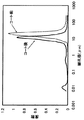
本発明の排ガス浄化用フィルタは、前記構成を有していることから、水銀ポロシメータにより細孔径分布曲線を測定すると、図1に例示する通りに、炭化珪素粒子とセラミック酸化物粒子から形成される1μm以上の細孔径にピークを持つ分布と、前記セラミック酸化物粒子内の細孔に拠る0.1μm以下の細孔径にピークを持つ複数のピークを有する分布曲線が得られる。
【0020】
本発明に於いて、本発明者の実験的検討に拠れば、前者の細孔の平均気孔径が5〜20μmであり、しかも気孔率が40〜60%であることが好ましい。前記の好適な範囲の下限値よりも小さいと、実使用において、フィルタの圧力損失が高くなりエンジン出力が低下することがあるので望ましくないし、一方、好適な範囲の上限値を越えると、PMの捕集効率が低下することがあり好ましくない。
【0021】
また、本発明に於いて、触媒成分の分散性や初期状態におけるガスの拡散性を高めるために触媒担体であるセラミック酸化物粒子の比表面積(m2/g)の平均粒径(μm)に対する比が30以上であることが好ましい。前記の比が30よりも小さいと、セラミックス酸化物粒子一つ当たりの触媒担持量が少なくなり、触媒を有効に作用させるために多量のセラミックス酸化物粒子をコーティングする必要があり、前記の気孔特性が得難くなるからである。
【0022】
本発明に於いて、酸化触媒としては、金、銀、銅、鉄、亜鉛、マンガン、セリウム及び白金属元素からなる群の中から選ばれる1種又は2種以上を含有するものが好ましい。また、その含有量としては、0.3〜7g/l(ハニカム単位体積当たり)であることが好ましい。0.3g/lよりも少ないと、低温活性や浄化性能において十分に機能が発揮されず、7g/lを超えると触媒活性が飽和するので、経済的に得策でない。
【0023】
本発明に於けるセラミック酸化物粒子としては、Al、Zr、Ti、Siからなる群から選ばれる1種以上の元素からなる酸化物が好ましく、特にγ―アルミナが好適に選択される。γ―アルミナは、比表面積が非常に大きな微粉として入手しやすいし、更に、前記の高い比(比表面積/平均粒径)を得やすいからである。
【0024】
本発明に於いて、いろいろな酸化触媒をγ―アルミナ等のセラミック酸化物粒子からなる触媒担体に担持する方法としては、例えば含浸法や混練法等の公知の方法の中から適宜選択して行うことができる。また、酸化触媒の原料化合物としては、ジニトロジアンミン酸塩、塩化物、硝酸塩等の水溶性のものであれば任意のものが使用できる。また、水の除去は、例えば、濾過法や蒸発乾固法の公知の方法の中から適宜選択して行うことができる。
【0025】
触媒成分のフィルタへの担持は、触媒成分を含むスラリー中にフィルタを浸積する、或いは端面から触媒成分を含むスラリーを吹きかける等の方法により得られるが、ハニカム壁内部の炭化珪素粒子表面に均一にコーティングするためには、スラリー浸積法が好ましい。
【0026】
酸化触媒の総担持量(触媒成分とアルミナ等の担体の量)は20〜200g/l(ハニカム単位体積当たり)が好ましい。コート量が多いほど、触媒活性や触媒寿命の面から好ましいが、コート層が厚くなりすぎると前記の気孔特性を得難くなり、圧力損失の増加を引き起こし、好ましくないからである。
【0027】
【実施例】
(実施例1、2、比較例1、2、3)
【0028】
<<排ガス浄化用フィルタの作製>>
(実施例1)
<フィルタ材料>
端面の外径寸法143.8mm、軸方向長さ152.4mm、壁厚0.34mm、セル密度200個/平方インチでセル端部を市松模様状に封止した炭化珪素焼結体からなるウォールフロー型ハニカムフィルタを使用した。インターセプト法により求めた焼結体の炭化珪素粒子の平均粒子径は18μmであった。水銀圧入法により求めた平均気孔径は18μmで気孔率は55%であった。
【0029】
<触媒含有スラリー調製>
比表面積120m2/g、平均粒径50μmのγ―アルミナ粉末にジニトロジアンミン白金水溶液を撹拌しながら噴霧し、150℃で24時間乾燥した後、400℃で1時間、次いで600℃で1時間焼成し、Pt担持アルミナ粉末を得た。この粉末のPt濃度は1.0質量%であった。次に、前記粉末を40質量%、酢酸性アルミナゾル(日産化学製、アルミナゾル200)を2質量%及び蒸留水58質量%を磁性ボールミルに投入し、100時間の混合粉砕を行ってスラリーを得た。JIS R1629に準じスラリー中の粉末の平均粒径をレーザー回折・散乱法により測定したところ、1.0μmであり、炭化珪素粒子の平均粒径に対する比は0.06で、γ―アルミナの比表面積(m2/g)/平均粒径の比は120であった。
【0030】
<フィルタへの触媒成分担持>
前記スラリーを蒸留水により所定濃度に希釈した後、前記フィルタを浸積し、触媒成分を付着させ、空気流にてセル内の余剰スラリーを取り除いて乾燥した。その後、600℃で3時間焼成し、フィルタの単位体積当たりのコート量が50g/lの排ガス浄化用フィルタを得た。触媒成分担持前後で水銀ポロシメータにより測定した細孔径分布曲線を図1に示す。触媒成分のコーティングによりコート前のピークが低気孔径側にシフトし、また0.05μm付近にγ―アルミナ粒子内の細孔に基づくピークが見られた。気孔径が0.5μm以下のピーク以外から算出される平均気孔径は14μmであり、気孔率は52%であった。
【0031】
(実施例2)
<フィルタ材料>
端面の外径寸法143.8mm、軸方向長さ152.4mm、壁厚0.20mm、セル密度300個/平方インチの炭化珪素焼結体からなるフィルタを使用した。炭化珪素の平均粒子径は18μmで、水銀ポロシメータにより測定した平均気孔径は30μmで気孔率は60%であった。
【0032】
<触媒含有スラリー調製>
実施例1と同じ方法で触媒含有スラリーを調製した。
【0033】
<フィルタへの触媒成分担持>
実施例1と同様の触媒成分付着処理を4回繰り返した後、600℃で3時間焼成して排ガス浄化用フィルタを得た。コート量は180g/lで、水銀ポロシメータにより測定した気孔径が0.5μm以下のピーク以外から算出される平均気孔径は19μmで、気孔率は52%であった。
【0034】
(比較例1)
<フィルタ材料>
実施例1と同じものを使用した。
【0035】
<触媒含有スラリー調製>
実施例1と同じ方法で触媒含有スラリーを調製した。但し、ボールミルによる粉砕混合時間を5時間とした。スラリー中の粉末の平均粒径は10μmであり、炭化珪素粒子の平均粒径に対する比は0.56で、γ―アルミナの比表面積(m2/g)/平均粒径の比は12であった。
【0036】
<フィルタへの触媒成分担持>
実施例1と同様の触媒成分付着処理を行った。コート量は50g/lで、水銀ポロシメータにより測定した気孔径が0.5μm以下のピーク以外から算出される平均気孔径は13μmで気孔率は52%であった。
【0037】
(比較例2)
<フィルタ材料>
端面の外径寸法143.8mm、軸方向長さ152.4mm、壁厚0.34mm、セル密度200個/平方インチでセル端部を市松模様状に封止した炭化珪素焼結体からなるウォールフロー型ハニカムフィルタを使用した。インターセプト法により求めた焼結体の炭化珪素粒子の平均粒子径は23μmであった。水銀圧入法により求めた平均気孔径は9μmで気孔率は39%であった。
【0038】
<触媒含有スラリー調製>
実施例1と同じスラリーを使用した。γ―アルミナ粒子の平均粒径は炭化珪素粒子の平均粒径の0.04倍で、γ−アルミナの比表面積(m2/g)/平均粒径の比は120であった。
【0039】
<フィルタへの触媒成分担持>
実施例1と同様の触媒成分付着処理を行った。コート量は50g/lで、水銀ポロシメータにより測定した気孔径が0.5μm以下のピーク以外から算出される平均気孔径は4μmで気孔率は35%であった。
【0040】
(比較例3)
<フィルタ材料>
実施例2と同じものを使用した。
【0041】
<触媒含有スラリー調製>
実施例1と同じ方法で触媒含有スラリーを調製した。
【0042】
<フィルタへの触媒成分担持>
実施例1と同様の触媒成分付着処理を行った。コート量は50g/lで、水銀ポロシメータにより測定した気孔径が0.5μm以下のピーク以外から算出される平均気孔径は26μmで気孔率は57%であった。
【0043】
<<排ガス浄化用フィルタの圧力損失の測定>>
実施例1、2並びに比較例1〜3により得られたフィルタについて、フィルタの入口側から圧縮空気を流し、入口側と出口側の差圧を測定した。圧力損失の測定結果を図2に示す。水銀ポロシメータにより測定した気孔径が0.5μm以下のピーク以外から算出される平均気孔径及び/又は気孔率が大きくなるほど圧力損失が低くなる傾向が見られ、比較例2では圧力損失が著しく高くなった。また、比較例1は気孔径や気孔率の値の割には圧力損失が高くなった。
【0044】
<<排ガス浄化用フィルタの捕集効率及び耐久性の評価>>
実施例1,2及び比較例1,3により得られたフィルタについては、2000ccのディーゼルエンジン搭載車両に装着し、PMの捕集と再生を繰り返し、最長3万kmの走行試験を行った。
【0045】
実車走行試験前にフィルタ装着前後における黒煙濃度とPM低減率を測定したところ、実施例1、2及び比較例1のフィルタはいずれも黒煙濃度は100%の低減率であり、PM低減率は平均90%であった。一方、比較例3のフィルタは黒煙濃度は80%の低減率であり、PM低減率は平均50%と捕集効率が低いことが判った。
【0046】
実施例1及び実施例2の排ガス浄化用フィルタはいずれも約3万kmの走行で背圧の増加は見られず、PMの捕集と酸化による再生が効率良く行われていることが判った。また、走行試験後の黒煙濃度低減率は100%、PM低減率も平均90%であり、浄化性能が維持されていた。
【0047】
一方、比較例1の排ガス浄化用フィルタでは、走行距離が約3000kmを越えると背圧が急上昇し、走行試験を中止した。走行試験後のフィルタの微構造を観察したところ、ハニカム壁表面に触媒担体であるγ―アルミナ粒子がほとんど観察されず、セルの後方部に局在化していた。この場合、γ―アルミナとフィルタを構成する炭化珪素粒子との密着強度が不十分であり、走行試験中にγ―アルミナコート層の剥離が進行することにより、PMの酸化による再生機能が低下し、背圧が急上昇してしまったことが分かった。
【0048】
【発明の効果】
本発明のフィルタは、構成する炭化珪素粒子と担体の粒径との比を所定の範囲としていることから、さらにコーティング層形成後の気孔特性を適正化していることから、実使用条件下において、圧力損失が低く、PMの捕集性能に優れ、しかも担持した触媒の作用により、長期間にわたってマイルドな条件でPMを除去することができる特徴を有しているので、産業上非常に有用である。
【図面の簡単な説明】
【図1】実施例1に係る排ガス浄化用フィルタに関する、水銀ポロシメータにより測定した細孔径分布曲線を示す図。
【図2】実施例、比較例に係る排ガス浄化用フィルタの流量−圧力損出特性を示す図。[0001]
TECHNICAL FIELD OF THE INVENTION
TECHNICAL FIELD The present invention relates to an exhaust gas purifying filter for collecting and burning and removing fine particulate matter (also simply referred to as particulate matter) contained in exhaust gas of an engine.
[0002]
[Prior art]
In recent years, particulate matter (PM) emitted from a diesel engine or the like has become a major environmental health problem. PM mainly consists of solid carbon fine particles (SOOT) and liquid hydrocarbon fine particles (SOF: soluble organic fraction). Typical examples of the exhaust gas purifying filter include a honeycomb filter, a foam filter, and a fiber filter. In particular, cordierite and silicon carbide wall flow type honeycomb filters have been receiving attention as exhaust gas purifying filters for automobiles in view of heat resistance and trapping performance.
[0003]
As a typical method of burning and removing the collected PM, two honeycomb filters (hereinafter, referred to as filters) called an alternate regeneration system are used, and while one of the filters collects the PM, the PM is removed. The other filter deposited is heated to 600 ° C. or higher with a burner or an electric heater to burn the PM to regenerate the filter, and a method of repeated use or blowing back the PM deposited on the filter called a backwash method with air. After discharge from the filter, a method of burning the PM by heating it to 600 ° C. or higher with a burner, an electric heater or the like has been studied.
[0004]
However, in these methods, when the temperature of the filter rises rapidly due to the burning of PM, the problem that the filter is broken or melted occurs, and the cost is increased, the apparatus becomes large, and the filter can be easily mounted on an automobile or the like. There were problems such as not.
[0005]
Therefore, attention has been paid to a method in which an oxidation catalyst is supported on a honeycomb or a filter and PM is constantly burned at a low temperature. As the catalyst, for example, a technique for oxidizing NO in exhaust gas to NO 2 and oxidizing and burning PM with NO 2 (see Patent Document 1), or a combustion catalyst for a mixture of a platinum group metal and an alkaline earth metal oxide (See Patent Document 2) and the like have been proposed.
[0006]
[Patent Document 1] Japanese Patent No. 3012249.
[0007]
[Patent Document 2] Japanese Patent Publication No. 07-106290.
[0008]
[Problems to be solved by the invention]
In order to support a catalyst on a filter, a method is known in which a material having a high specific surface area such as γ-alumina is slurried as a carrier and coated on a cell side wall surface and inside pores of a cell side wall by wash coating. However, there is also a problem that the carrier falls off due to gas circulation, vibration, heat cycle, and the like in running the automobile for a long time, and the catalyst does not work effectively.
[0009]
Further, the formation of the coating layer has a problem that the pressure loss is higher than that of a filter without coating. Since a high pressure loss of the filter leads to a decrease in engine output, the pressure loss should be as low as possible. On the other hand, if the porosity and the pore diameter of the filter are too large to reduce the pressure loss, the PM collection efficiency will be reduced.
[0010]
[Means for Solving the Problems]
The present inventor has conducted intensive studies in view of the above-described conventional art, and has set the particle size ratio of the silicon carbide particles and the carrier constituting the filter to a predetermined range, thereby further improving the pore characteristics after forming the coating layer. By further optimizing, the above-mentioned problem can be further improved and the knowledge that the problem can be solved has been obtained, and the present invention has been achieved.The purpose of the present invention is that even under actual use conditions, An object of the present invention is to provide an exhaust gas purifying filter which is effective for a long time without falling off of a catalyst, has a high PM collection efficiency, and has a low pressure loss.
[0011]
That is, the present invention is a wall-flow type filter made of a porous silicon carbide sintered body, wherein ceramic oxide particles having pores on the surface of silicon carbide particles constituting the porous silicon carbide sintered body are provided. An exhaust gas purifying filter, further comprising an oxidation catalyst for oxidizing and burning particulate matter in exhaust gas collected by the filter in pores of the ceramic oxide particles, An exhaust gas purifying filter, wherein the average particle diameter of the particles is 0.002 to 0.2 times the average particle diameter of the silicon carbide particles.
[0012]
Further, in the present invention, when a pore size distribution curve is determined by a mercury intrusion method, the average pore size calculated from peaks other than a peak having a pore size of 0.5 μm or less is 5 to 20 μm, and the porosity is The exhaust gas purifying filter described above, which is 40 to 60%.
[0013]
Further, the present invention is the exhaust gas purifying filter, wherein the specific surface area (m 2 / g) of the ceramic oxide particles is 30 or more with respect to the average particle size (μm).
[0014]
Further, the present invention is characterized in that the oxidation catalyst contains one or more elements selected from the group consisting of gold, silver, copper, iron, zinc, manganese, cerium and platinum group elements. It is an exhaust gas purification filter.
[0015]
Further, the present invention is the above exhaust gas purifying filter, wherein the ceramic oxide particles are made of an oxide of at least one element selected from the group consisting of Al, Zr, Ti, and Si.
[0016]
BEST MODE FOR CARRYING OUT THE INVENTION
The exhaust gas purifying filter of the present invention is provided with ceramic oxide particles having pores on the surface of silicon carbide particles constituting the porous silicon carbide sintered body constituting the filter, and the pores of the ceramic oxide particles are provided. It has a structure that contains an oxidation catalyst for oxidizing and burning particulate matter in exhaust gas collected by the filter.
[0017]
The material of the exhaust gas purifying filter of the present invention is made of a porous sintered body made of silicon carbide because of its excellent heat resistance, thermal shock resistance, and corrosion resistance. Of a good wall flow type. As for the filter shape, it is preferable that the filter is a honeycomb filter, because the trapping performance of the particulate matter is more excellent and the production is easy.
[0018]
In the present invention, the average particle size of the ceramic oxide particles serving as the catalyst carrier is 0.002 to 0.2 times, preferably 0.01 to 0.2 times, the average particle size of the silicon carbide particles constituting the filter. It is 15 times. If it is larger than 0.2 times, the ratio of the contact area with the silicon carbide particles on the surface of the ceramic oxide particles is small, and sufficient adhesion cannot be obtained, and it becomes difficult to coat the inside of the pores of the silicon carbide sintered body. However, segregation occurs only on the surface of the honeycomb wall, and even when the carrier is carried in a small amount, the pressure loss may be greatly increased in actual use. On the other hand, powders smaller than 0.002 times are difficult to produce, agglomeration in the slurry drying step becomes extremely difficult, and uniform coating becomes difficult, contact between exhaust gas and the catalyst becomes insufficient, and desired catalyst performance is obtained. It becomes difficult.
[0019]
Since the exhaust gas purifying filter of the present invention has the above configuration, when a pore size distribution curve is measured by a mercury porosimeter, the filter is formed from silicon carbide particles and ceramic oxide particles as illustrated in FIG. A distribution curve having a peak at a pore diameter of 1 μm or more and a distribution curve having a plurality of peaks at a pore diameter of 0.1 μm or less due to pores in the ceramic oxide particles are obtained.
[0020]
According to the present inventors' experimental studies, the former preferably has an average pore diameter of 5 to 20 µm and a porosity of 40 to 60%. If it is smaller than the lower limit of the preferred range, the pressure loss of the filter becomes high and the engine output may decrease in practical use, which is not desirable. It is not preferable because the collection efficiency may be reduced.
[0021]
Further, in the present invention, the specific surface area (m 2 / g) of the ceramic oxide particles, which are the catalyst carrier, with respect to the average particle size (μm) in order to enhance the dispersibility of the catalyst component and the gas diffusion property in the initial state. Preferably, the ratio is 30 or more. If the above ratio is less than 30, the amount of catalyst carried per ceramic oxide particle becomes small, and it is necessary to coat a large amount of ceramic oxide particles in order to make the catalyst work effectively. Is difficult to obtain.
[0022]
In the present invention, the oxidation catalyst preferably contains one or more selected from the group consisting of gold, silver, copper, iron, zinc, manganese, cerium, and a white metal element. Further, the content is preferably 0.3 to 7 g / l (per unit volume of honeycomb). When the amount is less than 0.3 g / l, the function is not sufficiently exhibited in the low-temperature activity and the purification performance, and when the amount exceeds 7 g / l, the catalytic activity is saturated, which is not economically advantageous.
[0023]
As the ceramic oxide particles in the present invention, an oxide composed of at least one element selected from the group consisting of Al, Zr, Ti, and Si is preferable, and γ-alumina is particularly suitably selected. This is because γ-alumina is easily available as fine powder having a very large specific surface area, and it is easy to obtain the high ratio (specific surface area / average particle size).
[0024]
In the present invention, as a method of supporting various oxidation catalysts on a catalyst carrier composed of ceramic oxide particles such as γ-alumina, for example, an appropriate method is selected from known methods such as an impregnation method and a kneading method. be able to. As the raw material compound for the oxidation catalyst, any compound can be used as long as it is a water-soluble compound such as dinitrodiamminate, chloride and nitrate. The removal of water can be appropriately selected from known methods such as a filtration method and an evaporation to dryness method.
[0025]
The loading of the catalyst component on the filter can be obtained by immersing the filter in a slurry containing the catalyst component, or by spraying the slurry containing the catalyst component from the end face. For coating, a slurry immersion method is preferred.
[0026]
The total supported amount of the oxidation catalyst (the amount of the catalyst component and the carrier such as alumina) is preferably 20 to 200 g / l (per unit volume of the honeycomb). The larger the coating amount, the more preferable in terms of catalytic activity and catalyst life. However, if the coating layer is too thick, it becomes difficult to obtain the above-mentioned pore characteristics, causing an increase in pressure loss, which is not preferable.
[0027]
【Example】
(Examples 1, 2, Comparative Examples 1, 2, 3)
[0028]
<< Production of exhaust gas purification filter >>
(Example 1)
<Filter material>
A wall made of a silicon carbide sintered body having a cell end portion sealed in a checkered pattern at an outer diameter of 143.8 mm, an axial length of 152.4 mm, a wall thickness of 0.34 mm, and a cell density of 200 cells / square inch. A flow type honeycomb filter was used. The average particle size of the silicon carbide particles of the sintered body determined by the intercept method was 18 μm. The average pore diameter determined by the mercury intrusion method was 18 μm, and the porosity was 55%.
[0029]
<Preparation of catalyst-containing slurry>
An aqueous solution of dinitrodiammine platinum is sprayed onto γ-alumina powder having a specific surface area of 120 m 2 / g and an average particle size of 50 μm while stirring, dried at 150 ° C. for 24 hours, and then calcined at 400 ° C. for 1 hour and then at 600 ° C. for 1 hour. Thus, Pt-supported alumina powder was obtained. The Pt concentration of this powder was 1.0% by mass. Next, 40% by mass of the powder, 2% by mass of acetic acid alumina sol (manufactured by Nissan Chemical Co., Alumina Sol 200) and 58% by mass of distilled water were charged into a magnetic ball mill, and mixed and pulverized for 100 hours to obtain a slurry. . The average particle size of the powder in the slurry measured by a laser diffraction / scattering method according to JIS R1629 was 1.0 μm, the ratio of the average particle size of the silicon carbide particles to 0.06, and the specific surface area of γ-alumina The ratio of (m 2 / g) / average particle diameter was 120.
[0030]
<Loading of catalyst component on filter>
After diluting the slurry to a predetermined concentration with distilled water, the filter was immersed, a catalyst component was attached thereto, and excess slurry in the cell was removed with an air stream and dried. Thereafter, the filter was fired at 600 ° C. for 3 hours to obtain an exhaust gas purifying filter having a coating amount of 50 g / l per unit volume of the filter. FIG. 1 shows pore size distribution curves measured by a mercury porosimeter before and after carrying the catalyst component. Due to the coating of the catalyst component, the peak before coating shifted to the low pore size side, and a peak based on pores in γ-alumina particles was observed at around 0.05 μm. The average pore diameter calculated from the peaks other than those having a pore diameter of 0.5 μm or less was 14 μm, and the porosity was 52%.
[0031]
(Example 2)
<Filter material>
A filter made of a silicon carbide sintered body having an outer diameter of 143.8 mm at the end face, an axial length of 152.4 mm, a wall thickness of 0.20 mm, and a cell density of 300 cells / square inch was used. The average particle diameter of silicon carbide was 18 μm, the average pore diameter measured by a mercury porosimeter was 30 μm, and the porosity was 60%.
[0032]
<Preparation of catalyst-containing slurry>
A catalyst-containing slurry was prepared in the same manner as in Example 1.
[0033]
<Loading of catalyst component on filter>
After the same catalyst component attachment treatment as in Example 1 was repeated four times, it was fired at 600 ° C. for 3 hours to obtain an exhaust gas purifying filter. The coating amount was 180 g / l, the average pore diameter calculated from the peaks other than the peak having a pore diameter of 0.5 μm or less measured by a mercury porosimeter was 19 μm, and the porosity was 52%.
[0034]
(Comparative Example 1)
<Filter material>
The same one as in Example 1 was used.
[0035]
<Preparation of catalyst-containing slurry>
A catalyst-containing slurry was prepared in the same manner as in Example 1. However, the pulverization mixing time by the ball mill was 5 hours. The average particle size of the powder in the slurry was 10 μm, the ratio to the average particle size of the silicon carbide particles was 0.56, and the ratio of the specific surface area (m 2 / g) / average particle size of γ-alumina was 12. Was.
[0036]
<Loading of catalyst component on filter>
The same catalyst component adhesion treatment as in Example 1 was performed. The coating amount was 50 g / l, the average pore size calculated from the peaks other than the peak having a pore size of 0.5 μm or less measured by a mercury porosimeter was 13 μm, and the porosity was 52%.
[0037]
(Comparative Example 2)
<Filter material>
A wall made of a silicon carbide sintered body having a cell end portion sealed in a checkered pattern at an outer diameter of 143.8 mm, an axial length of 152.4 mm, a wall thickness of 0.34 mm, and a cell density of 200 cells / square inch. A flow type honeycomb filter was used. The average particle size of the silicon carbide particles of the sintered body determined by the intercept method was 23 μm. The average pore diameter determined by the mercury intrusion method was 9 μm, and the porosity was 39%.
[0038]
<Preparation of catalyst-containing slurry>
The same slurry as in Example 1 was used. The average particle size of the γ-alumina particles was 0.04 times the average particle size of the silicon carbide particles, and the ratio of specific surface area (m 2 / g) / average particle size of γ-alumina was 120.
[0039]
<Loading of catalyst component on filter>
The same catalyst component adhesion treatment as in Example 1 was performed. The coating amount was 50 g / l, the average pore diameter calculated from the peaks other than the peak having a pore diameter of 0.5 μm or less measured by a mercury porosimeter was 4 μm, and the porosity was 35%.
[0040]
(Comparative Example 3)
<Filter material>
The same one as in Example 2 was used.
[0041]
<Preparation of catalyst-containing slurry>
A catalyst-containing slurry was prepared in the same manner as in Example 1.
[0042]
<Loading of catalyst component on filter>
The same catalyst component adhesion treatment as in Example 1 was performed. The coating amount was 50 g / l, the average pore diameter calculated from the peaks other than the peak having a pore diameter of 0.5 μm or less measured by a mercury porosimeter was 26 μm, and the porosity was 57%.
[0043]
<< Measurement of pressure loss of exhaust gas purification filter >>
With respect to the filters obtained in Examples 1 and 2 and Comparative Examples 1 to 3, compressed air was flowed from the inlet side of the filter, and the differential pressure between the inlet side and the outlet side was measured. FIG. 2 shows the measurement results of the pressure loss. As the average pore diameter and / or the porosity calculated from peaks other than those having a pore diameter measured by a mercury porosimeter of 0.5 μm or less increase, the pressure loss tends to decrease. In Comparative Example 2, the pressure loss significantly increases. Was. In Comparative Example 1, the pressure loss was higher than the values of the pore diameter and the porosity.
[0044]
<< Evaluation of collection efficiency and durability of exhaust gas purification filter >>
The filters obtained in Examples 1 and 2 and Comparative Examples 1 and 3 were mounted on a vehicle equipped with a 2000 cc diesel engine, and PM collection and regeneration were repeated, and a running test of up to 30,000 km was performed.
[0045]
The black smoke density and the PM reduction rate before and after the filter was attached were measured before the actual vehicle running test. The black smoke density of the filters of Examples 1 and 2 and Comparative Example 1 was 100%, and the PM reduction rate was 100%. Was 90% on average. On the other hand, it was found that the filter of Comparative Example 3 had a black smoke density of 80% reduction rate and a PM reduction rate of 50% on average and low collection efficiency.
[0046]
In each of the exhaust gas purifying filters of Example 1 and Example 2, no increase in back pressure was observed after traveling about 30,000 km, and it was found that PM was collected and regeneration by oxidation was performed efficiently. . Further, the black smoke concentration reduction rate after the running test was 100%, and the PM reduction rate was 90% on average, and the purification performance was maintained.
[0047]
On the other hand, in the exhaust gas purifying filter of Comparative Example 1, when the traveling distance exceeded about 3000 km, the back pressure rapidly increased, and the traveling test was stopped. When the microstructure of the filter after the running test was observed, almost no γ-alumina particles as the catalyst carrier were observed on the surface of the honeycomb wall, and the particles were localized in the rear part of the cell. In this case, the adhesion strength between γ-alumina and the silicon carbide particles constituting the filter is insufficient, and the peeling of the γ-alumina coat layer progresses during the running test, so that the regeneration function due to oxidation of PM deteriorates. It turned out that the back pressure had risen sharply.
[0048]
【The invention's effect】
The filter of the present invention, since the ratio of the particle size of the silicon carbide particles and the carrier constituting the carrier is in a predetermined range, furthermore, since the pore characteristics after forming the coating layer is optimized, under actual use conditions, It is very useful in industry because it has the characteristics of low pressure loss, excellent PM trapping performance, and the ability to remove PM under mild conditions over a long period of time by the action of the supported catalyst. .
[Brief description of the drawings]
FIG. 1 is a view showing a pore size distribution curve of an exhaust gas purifying filter according to Example 1 measured by a mercury porosimeter.
FIG. 2 is a graph showing flow rate-pressure loss characteristics of exhaust gas purifying filters according to examples and comparative examples.
Claims (5)
Priority Applications (1)
| Application Number | Priority Date | Filing Date | Title |
|---|---|---|---|
| JP2003131009A JP2004330118A (en) | 2003-05-09 | 2003-05-09 | Filter for clarifying exhaust gas |
Applications Claiming Priority (1)
| Application Number | Priority Date | Filing Date | Title |
|---|---|---|---|
| JP2003131009A JP2004330118A (en) | 2003-05-09 | 2003-05-09 | Filter for clarifying exhaust gas |
Publications (1)
| Publication Number | Publication Date |
|---|---|
| JP2004330118A true JP2004330118A (en) | 2004-11-25 |
Family
ID=33506296
Family Applications (1)
| Application Number | Title | Priority Date | Filing Date |
|---|---|---|---|
| JP2003131009A Pending JP2004330118A (en) | 2003-05-09 | 2003-05-09 | Filter for clarifying exhaust gas |
Country Status (1)
| Country | Link |
|---|---|
| JP (1) | JP2004330118A (en) |
Cited By (15)
| Publication number | Priority date | Publication date | Assignee | Title |
|---|---|---|---|---|
| WO2006035823A1 (en) * | 2004-09-30 | 2006-04-06 | Ibiden Co., Ltd. | Honeycomb structure |
| WO2006041174A1 (en) * | 2004-10-12 | 2006-04-20 | Ibiden Co., Ltd. | Ceramic honeycomb structure |
| JP2006255574A (en) * | 2005-03-16 | 2006-09-28 | Ibiden Co Ltd | Honeycomb structure |
| JP2006346579A (en) * | 2005-06-16 | 2006-12-28 | Toyota Central Res & Dev Lab Inc | Exhaust gas cleaning filter, and its manufacturing method |
| EP1852184A1 (en) * | 2004-12-27 | 2007-11-07 | Ibiden Co., Ltd. | Ceramic honeycomb structure |
| JP2009517207A (en) * | 2005-11-30 | 2009-04-30 | サン−ゴバン サントル ドゥ ルシェルシェ エ デトゥードゥ ユーロペン | Silicon carbide based gas filtration structure with controlled wall surface porosity |
| JP2009136787A (en) * | 2007-12-06 | 2009-06-25 | Honda Motor Co Ltd | Method of manufacturing oxidation catalyst device for purification of exhaust gas |
| JP2009255047A (en) * | 2008-03-24 | 2009-11-05 | Ibiden Co Ltd | Honeycomb structure |
| WO2010013509A1 (en) * | 2008-07-28 | 2010-02-04 | 日立金属株式会社 | Ceramic honeycomb structure and process for producing the same |
| JP2010099557A (en) * | 2008-10-21 | 2010-05-06 | Sumitomo Osaka Cement Co Ltd | Metal catalyst support particle, method for manufacturing the same, metal-catalyst-support-particle dispersion liquid, and catalyst |
| JP2010516466A (en) * | 2007-01-31 | 2010-05-20 | ビーエーエスエフ、カタリスツ、エルエルシー | Gas catalyst with porous wall honeycomb |
| JP2012196656A (en) * | 2011-03-23 | 2012-10-18 | Ngk Insulators Ltd | Honeycomb filter |
| JP2018122261A (en) * | 2017-02-02 | 2018-08-09 | 日本碍子株式会社 | Plugged Honeycomb Structure |
| JPWO2017119101A1 (en) * | 2016-01-07 | 2018-12-13 | ジョンソン・マッセイ・ジャパン合同会社 | filter |
| WO2020031794A1 (en) * | 2018-08-09 | 2020-02-13 | エヌ・イーケムキャット株式会社 | Exhaust gas purification catalyst |
-
2003
- 2003-05-09 JP JP2003131009A patent/JP2004330118A/en active Pending
Cited By (32)
| Publication number | Priority date | Publication date | Assignee | Title |
|---|---|---|---|---|
| JPWO2006035823A1 (en) * | 2004-09-30 | 2008-05-15 | イビデン株式会社 | Honeycomb structure |
| WO2006035823A1 (en) * | 2004-09-30 | 2006-04-06 | Ibiden Co., Ltd. | Honeycomb structure |
| US7449427B2 (en) | 2004-09-30 | 2008-11-11 | Ibiden Co., Ltd | Honeycomb structured body |
| US7524350B2 (en) | 2004-10-12 | 2009-04-28 | Ibiden Co., Ltd. | Ceramic honeycomb structural body |
| JPWO2006041174A1 (en) * | 2004-10-12 | 2008-05-22 | イビデン株式会社 | Ceramic honeycomb structure |
| WO2006041174A1 (en) * | 2004-10-12 | 2006-04-20 | Ibiden Co., Ltd. | Ceramic honeycomb structure |
| JP5001009B2 (en) * | 2004-10-12 | 2012-08-15 | イビデン株式会社 | Ceramic honeycomb structure |
| EP1852184A1 (en) * | 2004-12-27 | 2007-11-07 | Ibiden Co., Ltd. | Ceramic honeycomb structure |
| EP1852184A4 (en) * | 2004-12-27 | 2008-02-06 | Ibiden Co Ltd | Ceramic honeycomb structure |
| US8192517B2 (en) | 2004-12-27 | 2012-06-05 | Ibiden Co., Ltd. | Ceramic honeycomb structural body |
| JP2006255574A (en) * | 2005-03-16 | 2006-09-28 | Ibiden Co Ltd | Honeycomb structure |
| US8003190B2 (en) | 2005-03-16 | 2011-08-23 | Ibiden Co. Ltd | Honeycomb structure |
| JP2006346579A (en) * | 2005-06-16 | 2006-12-28 | Toyota Central Res & Dev Lab Inc | Exhaust gas cleaning filter, and its manufacturing method |
| JP2009517207A (en) * | 2005-11-30 | 2009-04-30 | サン−ゴバン サントル ドゥ ルシェルシェ エ デトゥードゥ ユーロペン | Silicon carbide based gas filtration structure with controlled wall surface porosity |
| KR101323404B1 (en) * | 2005-11-30 | 2013-11-04 | 생-고뱅 생트레 드 레체르체 에 데투드 유로삐엔 | Structure for the filtration of a gas based on silicium carbide with a controlled wall surface porosity |
| US8105543B2 (en) | 2005-11-30 | 2012-01-31 | Saint-Gobain Centre De Recherches Et D'etudes Europeen | Silicon carbide based structure for filtrating gas |
| JP2010516466A (en) * | 2007-01-31 | 2010-05-20 | ビーエーエスエフ、カタリスツ、エルエルシー | Gas catalyst with porous wall honeycomb |
| KR101536012B1 (en) * | 2007-01-31 | 2015-07-13 | 바스프 카탈리스트 엘엘씨 | Gas catalysts comprising porous wall honeycombs |
| JP2009136787A (en) * | 2007-12-06 | 2009-06-25 | Honda Motor Co Ltd | Method of manufacturing oxidation catalyst device for purification of exhaust gas |
| JP2009255047A (en) * | 2008-03-24 | 2009-11-05 | Ibiden Co Ltd | Honeycomb structure |
| KR20110048506A (en) * | 2008-07-28 | 2011-05-11 | 히타치 긴조쿠 가부시키가이샤 | Ceramic honeycomb structure and its manufacturing method |
| CN102089058B (en) * | 2008-07-28 | 2014-03-12 | 日立金属株式会社 | Ceramic honeycomb structure and process for producing same |
| US8691361B2 (en) | 2008-07-28 | 2014-04-08 | Hitachi Metals, Ltd. | Ceramic honeycomb structure and its production method |
| JP5464142B2 (en) * | 2008-07-28 | 2014-04-09 | 日立金属株式会社 | Ceramic honeycomb structure and manufacturing method thereof |
| WO2010013509A1 (en) * | 2008-07-28 | 2010-02-04 | 日立金属株式会社 | Ceramic honeycomb structure and process for producing the same |
| KR101648483B1 (en) * | 2008-07-28 | 2016-08-16 | 히타치 긴조쿠 가부시키가이샤 | Ceramic honeycomb structure and process for producing the same |
| JP2010099557A (en) * | 2008-10-21 | 2010-05-06 | Sumitomo Osaka Cement Co Ltd | Metal catalyst support particle, method for manufacturing the same, metal-catalyst-support-particle dispersion liquid, and catalyst |
| JP2012196656A (en) * | 2011-03-23 | 2012-10-18 | Ngk Insulators Ltd | Honeycomb filter |
| JPWO2017119101A1 (en) * | 2016-01-07 | 2018-12-13 | ジョンソン・マッセイ・ジャパン合同会社 | filter |
| JP2018122261A (en) * | 2017-02-02 | 2018-08-09 | 日本碍子株式会社 | Plugged Honeycomb Structure |
| WO2020031794A1 (en) * | 2018-08-09 | 2020-02-13 | エヌ・イーケムキャット株式会社 | Exhaust gas purification catalyst |
| JP2020025954A (en) * | 2018-08-09 | 2020-02-20 | エヌ・イーケムキャット株式会社 | Catalyst for cleaning exhaust gas |
Similar Documents
| Publication | Publication Date | Title |
|---|---|---|
| KR950002223B1 (en) | Catalyst for purification of exhausted gas from diesel engine | |
| JP5697299B2 (en) | Catalytic converter | |
| JP3560408B2 (en) | Diesel exhaust gas purification filter and method for producing the same | |
| JP4393039B2 (en) | Filter with catalyst, method for manufacturing the same, and exhaust gas purification system | |
| JP5447757B2 (en) | Catalyst coated particle filter, process for its production and use thereof | |
| JP4275406B2 (en) | Catalyst support filter | |
| JP5237630B2 (en) | Honeycomb structure | |
| EP1679119B1 (en) | Method of production of a filter catalyst for exhaust gas purification of a diesel engine | |
| JP4274937B2 (en) | Smoke filter, method for manufacturing smoke filter, and method for using smoke filter | |
| JP4640868B2 (en) | Filter with catalyst, method for manufacturing the same, and exhaust gas purification system | |
| JP2003080080A (en) | Ceramic filter and ceramic filter with catalyst | |
| JPH09173866A (en) | Diesel exhaust gas purifying filter | |
| JP2004330118A (en) | Filter for clarifying exhaust gas | |
| JP2006520264A (en) | Catalyzed filters for diesel engines and diesel engines | |
| JP2007144371A (en) | Catalyst for cleaning exhaust gas and its manufacturing method | |
| JP4210552B2 (en) | Diesel engine exhaust gas purification catalyst and method for producing the same | |
| JP2001327818A (en) | Ceramic filter and filtration device | |
| KR20080057336A (en) | Exhaust gas purifying apparatus | |
| JP4715032B2 (en) | Diesel exhaust gas purification filter | |
| JP2004058013A (en) | Purification catalyst for exhaust gas | |
| JP2008151100A (en) | Exhaust emission control device | |
| JP4057811B2 (en) | Engine exhaust gas purification catalyst | |
| JP2005007360A (en) | Exhaust gas cleaning filter | |
| EP1979070A1 (en) | Exhaust gas-purifying catalyst | |
| KR20030061898A (en) | Soot Filtration Filter and Device for Reducing Soot Using the Same |
Legal Events
| Date | Code | Title | Description |
|---|---|---|---|
| A621 | Written request for application examination |
Free format text: JAPANESE INTERMEDIATE CODE: A621 Effective date: 20060209 |
|
| A977 | Report on retrieval |
Free format text: JAPANESE INTERMEDIATE CODE: A971007 Effective date: 20071121 |
|
| A131 | Notification of reasons for refusal |
Free format text: JAPANESE INTERMEDIATE CODE: A131 Effective date: 20071127 |
|
| A521 | Request for written amendment filed |
Free format text: JAPANESE INTERMEDIATE CODE: A523 Effective date: 20080110 |
|
| A131 | Notification of reasons for refusal |
Free format text: JAPANESE INTERMEDIATE CODE: A131 Effective date: 20080319 |
|
| A02 | Decision of refusal |
Free format text: JAPANESE INTERMEDIATE CODE: A02 Effective date: 20080715 |