JP2006520264A - Catalyzed filters for diesel engines and diesel engines - Google Patents
Catalyzed filters for diesel engines and diesel engines Download PDFInfo
- Publication number
- JP2006520264A JP2006520264A JP2006505908A JP2006505908A JP2006520264A JP 2006520264 A JP2006520264 A JP 2006520264A JP 2006505908 A JP2006505908 A JP 2006505908A JP 2006505908 A JP2006505908 A JP 2006505908A JP 2006520264 A JP2006520264 A JP 2006520264A
- Authority
- JP
- Japan
- Prior art keywords
- filter
- engine
- engine according
- catalyst
- exhaust gas
- Prior art date
- Legal status (The legal status is an assumption and is not a legal conclusion. Google has not performed a legal analysis and makes no representation as to the accuracy of the status listed.)
- Pending
Links
Images
Classifications
-
- F—MECHANICAL ENGINEERING; LIGHTING; HEATING; WEAPONS; BLASTING
- F01—MACHINES OR ENGINES IN GENERAL; ENGINE PLANTS IN GENERAL; STEAM ENGINES
- F01N—GAS-FLOW SILENCERS OR EXHAUST APPARATUS FOR MACHINES OR ENGINES IN GENERAL; GAS-FLOW SILENCERS OR EXHAUST APPARATUS FOR INTERNAL COMBUSTION ENGINES
- F01N3/00—Exhaust or silencing apparatus having means for purifying, rendering innocuous, or otherwise treating exhaust
- F01N3/02—Exhaust or silencing apparatus having means for purifying, rendering innocuous, or otherwise treating exhaust for cooling, or for removing solid constituents of, exhaust
- F01N3/021—Exhaust or silencing apparatus having means for purifying, rendering innocuous, or otherwise treating exhaust for cooling, or for removing solid constituents of, exhaust by means of filters
- F01N3/033—Exhaust or silencing apparatus having means for purifying, rendering innocuous, or otherwise treating exhaust for cooling, or for removing solid constituents of, exhaust by means of filters in combination with other devices
- F01N3/035—Exhaust or silencing apparatus having means for purifying, rendering innocuous, or otherwise treating exhaust for cooling, or for removing solid constituents of, exhaust by means of filters in combination with other devices with catalytic reactors, e.g. catalysed diesel particulate filters
-
- B—PERFORMING OPERATIONS; TRANSPORTING
- B01—PHYSICAL OR CHEMICAL PROCESSES OR APPARATUS IN GENERAL
- B01D—SEPARATION
- B01D53/00—Separation of gases or vapours; Recovering vapours of volatile solvents from gases; Chemical or biological purification of waste gases, e.g. engine exhaust gases, smoke, fumes, flue gases, aerosols
- B01D53/34—Chemical or biological purification of waste gases
- B01D53/92—Chemical or biological purification of waste gases of engine exhaust gases
- B01D53/94—Chemical or biological purification of waste gases of engine exhaust gases by catalytic processes
- B01D53/9459—Removing one or more of nitrogen oxides, carbon monoxide, or hydrocarbons by multiple successive catalytic functions; systems with more than one different function, e.g. zone coated catalysts
- B01D53/9463—Removing one or more of nitrogen oxides, carbon monoxide, or hydrocarbons by multiple successive catalytic functions; systems with more than one different function, e.g. zone coated catalysts with catalysts positioned on one brick
- B01D53/9472—Removing one or more of nitrogen oxides, carbon monoxide, or hydrocarbons by multiple successive catalytic functions; systems with more than one different function, e.g. zone coated catalysts with catalysts positioned on one brick in different zones
-
- B—PERFORMING OPERATIONS; TRANSPORTING
- B01—PHYSICAL OR CHEMICAL PROCESSES OR APPARATUS IN GENERAL
- B01D—SEPARATION
- B01D53/00—Separation of gases or vapours; Recovering vapours of volatile solvents from gases; Chemical or biological purification of waste gases, e.g. engine exhaust gases, smoke, fumes, flue gases, aerosols
- B01D53/34—Chemical or biological purification of waste gases
- B01D53/92—Chemical or biological purification of waste gases of engine exhaust gases
- B01D53/94—Chemical or biological purification of waste gases of engine exhaust gases by catalytic processes
- B01D53/9495—Controlling the catalytic process
-
- F—MECHANICAL ENGINEERING; LIGHTING; HEATING; WEAPONS; BLASTING
- F01—MACHINES OR ENGINES IN GENERAL; ENGINE PLANTS IN GENERAL; STEAM ENGINES
- F01N—GAS-FLOW SILENCERS OR EXHAUST APPARATUS FOR MACHINES OR ENGINES IN GENERAL; GAS-FLOW SILENCERS OR EXHAUST APPARATUS FOR INTERNAL COMBUSTION ENGINES
- F01N3/00—Exhaust or silencing apparatus having means for purifying, rendering innocuous, or otherwise treating exhaust
- F01N3/02—Exhaust or silencing apparatus having means for purifying, rendering innocuous, or otherwise treating exhaust for cooling, or for removing solid constituents of, exhaust
- F01N3/021—Exhaust or silencing apparatus having means for purifying, rendering innocuous, or otherwise treating exhaust for cooling, or for removing solid constituents of, exhaust by means of filters
- F01N3/022—Exhaust or silencing apparatus having means for purifying, rendering innocuous, or otherwise treating exhaust for cooling, or for removing solid constituents of, exhaust by means of filters characterised by specially adapted filtering structure, e.g. honeycomb, mesh or fibrous
- F01N3/0222—Exhaust or silencing apparatus having means for purifying, rendering innocuous, or otherwise treating exhaust for cooling, or for removing solid constituents of, exhaust by means of filters characterised by specially adapted filtering structure, e.g. honeycomb, mesh or fibrous the structure being monolithic, e.g. honeycombs
-
- F—MECHANICAL ENGINEERING; LIGHTING; HEATING; WEAPONS; BLASTING
- F02—COMBUSTION ENGINES; HOT-GAS OR COMBUSTION-PRODUCT ENGINE PLANTS
- F02D—CONTROLLING COMBUSTION ENGINES
- F02D41/00—Electrical control of supply of combustible mixture or its constituents
- F02D41/02—Circuit arrangements for generating control signals
- F02D41/021—Introducing corrections for particular conditions exterior to the engine
- F02D41/0235—Introducing corrections for particular conditions exterior to the engine in relation with the state of the exhaust gas treating apparatus
- F02D41/027—Introducing corrections for particular conditions exterior to the engine in relation with the state of the exhaust gas treating apparatus to purge or regenerate the exhaust gas treating apparatus
- F02D41/029—Introducing corrections for particular conditions exterior to the engine in relation with the state of the exhaust gas treating apparatus to purge or regenerate the exhaust gas treating apparatus the exhaust gas treating apparatus being a particulate filter
Abstract
排気機構を備えてなるディーゼルエンジンであって、平均細孔直径が5μm〜40μmであり、多孔率が少なくとも40%であり、バルク体積熱容量が500℃で少なくとも0.50Jcm−3K−1である多孔質材料から製造された粒子状フィルターを備えてなり、該フィルターは、フィルター前端部区域に配置された、一酸化炭素、炭化水素および一酸化窒素を酸化するためのディーゼル酸化触媒を含んでなり、該エンジンは、使用中に、十分な酸化窒素または炭化水素を含んでなる排ガスおよび/またはフィルター中の粒子状物質を燃焼させるのに十分に高い温度を有する排ガスを連続的または間欠的に供給するエンジン管理手段を備えてなる。A diesel engine equipped with an exhaust mechanism, having an average pore diameter of 5 μm to 40 μm, a porosity of at least 40%, and a bulk volume heat capacity of at least 0.50 Jcm −3 K −1 at 500 ° C. Comprising a particulate filter made of a porous material, the filter comprising a diesel oxidation catalyst for oxidizing carbon monoxide, hydrocarbons and nitric oxide disposed in the front end region of the filter The engine continuously or intermittently supplies, during use, exhaust gas comprising sufficient nitric oxide or hydrocarbons and / or exhaust gas having a sufficiently high temperature to burn particulate matter in the filter It comprises engine management means.
Description
本発明は、粒子状フィルターを備えてなる排気機構を備えてなるディーゼルエンジンに関する。特に、本発明は、触媒作用を付与した煤フィルターを備えてなるそのようなエンジンに関する。 The present invention relates to a diesel engine provided with an exhaust mechanism provided with a particulate filter. In particular, the invention relates to such an engine comprising a soot filter provided with a catalytic action.
内燃機関、例えばディーゼルエンジン、から許容される放出物は、政府により規制されている。規制されている排ガス種としては特に、酸化窒素(NOx)、一酸化炭素(CO)、炭化水素(HC)および粒子状物質(PM)が挙げられる。これらの化学種の許容される放出レベルは、今後10〜15年間に益々低下して行く。独自装置製造業者(OEM)は、エンジン設計と排ガス後処理の組合せにより、これらの法的必要条件に適合させようとしている。 Emissions allowed from internal combustion engines, such as diesel engines, are regulated by the government. The regulated exhaust gas species include in particular nitrogen oxide (NO x ), carbon monoxide (CO), hydrocarbon (HC) and particulate matter (PM). The acceptable release levels of these species will continue to decline over the next 10-15 years. Original equipment manufacturers (OEMs) are trying to meet these legal requirements through a combination of engine design and exhaust gas aftertreatment.
ディーゼルPMに対する既存および将来の法的必要条件に適合させるために、排ガス後処理用に提案されている装置の一つは粒子状フィルターである。ここで「フィルター」とは、我々は、排ガスから固体粒子を除去する装置、および粒子が排気機構を通って進行するのを遅延させようとする装置を意味する。後者の群の装置は、例えばヨーロッパ特許第EP1057519号明細書(ここに参考として含める)に記載されている。 In order to meet existing and future legal requirements for diesel PM, one of the devices proposed for exhaust gas aftertreatment is a particulate filter. By “filter” herein we mean a device that removes solid particles from the exhaust gas and a device that attempts to delay the progression of the particles through the exhaust mechanism. The latter group of devices is described, for example, in European Patent No. EP 1057519, which is hereby incorporated by reference.
粒子状フィルターの一例は、フィルターがハニカムの形態にあるウォール−フロ−フィルターである。このハニカムは、入口末端および出口末端、および入口末端から出口末端に向けて伸びる複数のセルを有し、セルは多孔質の壁を有し、セルの総数の一部は、入口末端で、例えば5〜20mmの深さに、それらの長さの一部に沿って塞がれており、セルの残り部分(入口末端で開いている)は、出口末端でそれらの長さの一部に沿って塞がれているので、入口末端からハニカムのセルを通って流れる排ガスは、開いたセルの中に流れ込み、セルの壁を通り、出口末端にある開いたセルを通ってフィルターから出る。セルを塞ぐための組成物は、米国特許第4,329,162号明細書(ここに参考として含める)に記載されている。典型的な配置では、特定面上の一つおきのセルが、碁盤縞のパターンで塞がれている。 An example of a particulate filter is a wall-flow filter where the filter is in the form of a honeycomb. The honeycomb has an inlet end and an outlet end, and a plurality of cells extending from the inlet end toward the outlet end, the cell has a porous wall, and a portion of the total number of cells is at the inlet end, for example Capped along part of their length to a depth of 5-20 mm, and the rest of the cells (open at the inlet end) along part of their length at the outlet end Thus, the exhaust gas flowing through the honeycomb cell from the inlet end flows into the open cell, passes through the cell wall and exits the filter through the open cell at the outlet end. Compositions for plugging cells are described in US Pat. No. 4,329,162, which is hereby incorporated by reference. In a typical arrangement, every other cell on a particular surface is plugged with a checkerboard pattern.
煤の燃焼温度を下げ、エンジン/車両の通常運転の際に経験する排気温度、典型的には300〜400℃で、PMの酸化によりフィルターを受動的に再生し易くするために、そのようなフィルターに触媒作用を付与することは公知である。触媒の非存在下では、PMは、500℃を超える温度でかなりの速度で酸化し得るが、この温度は、ディーゼルエンジンの通常運転ではほとんど見られない。そのような触媒作用を付与したフィルターは、触媒作用を付与した煤フィルター(またはCSF)と呼ばれることが多い。 In order to lower the soot combustion temperature, the exhaust temperature experienced during normal operation of the engine / vehicle, typically 300-400 ° C., to facilitate passive regeneration of the filter by oxidation of PM, such as It is known to impart catalytic action to filters. In the absence of catalyst, PM can oxidize at a significant rate at temperatures in excess of 500 ° C., but this temperature is rarely seen in normal operation of diesel engines. A filter imparted with such a catalytic action is often referred to as a soot filter (or CSF) imparted with a catalytic action.
受動的フィルター再生に伴う一般的な問題は、フィルターに触媒作用を付与することにより容易に得られるようになった低い温度(フィルター上へのPM蓄積を信頼性良く阻止するのに十分であることが多い)さえ、排ガス温度が走行条件により到達できなくなることである。そのような走行条件は、長時間のエンジンアイドリングまたは都市部の低速走行を包含し、この問題は、軽負荷ディーゼルエンジンから出る排ガスで特に顕著である。OEMにより採用されている、この問題の解決策の一つは、規則的な間隔で、または予め決められたフィルター背圧が検出された時に、受動的再生に加えて、フィルターを再生する能動的な技術を使用することである。軽負荷ディーゼル車両における典型的な配置では、CSFの上流にある別のモノリス上にディーゼル酸化触媒(DOC)を配置し、様々なエンジン管理技術によりシリンダー内における燃料の燃焼を制御し、排ガス中に導入される未燃焼燃料の量を増加する。この追加された燃料がDOC上で燃焼し、下流にあるCSF中の温度を十分に上昇させ、その上におけるPM燃焼を促進する。 A common problem with passive filter regeneration is that the low temperature that is easily obtained by catalyzing the filter (sufficient to reliably prevent PM buildup on the filter) The exhaust gas temperature cannot be reached due to driving conditions. Such driving conditions include long-term engine idling or urban low-speed driving, and this problem is particularly pronounced with exhaust gases from light-duty diesel engines. One solution to this problem employed by OEMs is to actively regenerate the filter in addition to passive regeneration at regular intervals or when a predetermined filter backpressure is detected. Is to use special technology. In a typical arrangement in a light-duty diesel vehicle, a diesel oxidation catalyst (DOC) is placed on a separate monolith upstream of the CSF, and various engine management techniques control the combustion of fuel in the cylinder and into the exhaust gas. Increase the amount of unburned fuel introduced. This added fuel burns on the DOC, sufficiently raising the temperature in the downstream CSF and promoting PM combustion thereon.
ヨーロッパ特許第EP−A−0341382号明細書または米国特許第US−A−4,902,487号明細書(両方ともここに参考として含める)は、濾過されていないPMおよびNOxを包含するディーゼル排ガスを酸化触媒上で処理し、NOをNO2に転化し、PMを酸化触媒下流にあるフィルター上に集め、トラップされたPMをNO2中で燃焼させる方法を記載している。この技術は、Johnson MattheyのCRT(商品名)として市販されている。この方法の利点は、NO2中でのPMの燃焼が400℃まで、すなわちディーゼル排ガスに対する通常の運転範囲に近い温度で起こることであり、これに対して、酸素中でのPM燃焼は550〜600℃で起こる。 EP EP-A-0341382 Pat or U.S. Patent No. US-A-4,902,487 Pat (both incorporated by reference herein), the diesel include PM and NO x unfiltered processes the exhaust gas over the oxidation catalyst, to convert the NO to NO 2, collected on a filter in a PM oxidation catalyst downstream, it describes a method for combusting the trapped PM in NO 2. This technology is commercially available as Johnson Matthey's CRT. The advantage of this method is that the combustion of PM in NO 2 occurs at temperatures up to 400 ° C., ie close to the normal operating range for diesel exhaust, whereas PM combustion in oxygen is 550-500. Occurs at 600 ° C.
我々の国際特許第WO01/12320号明細書(ここに参考として含める)は、PMを包含する汚染物を除去するための排ガス処理に特に好適な反応器を記載しているが、この反応器は、多孔質壁および交互に閉塞した末端を有するウォール−フロ−フィルター構造を備えてなり、触媒を担持するウォッシュコートが、フィルターの上流末端で開いた通路の上流末端にある区域に塗布されている。 Our International Patent No. WO 01/12320 (included here by reference) describes a reactor that is particularly suitable for exhaust gas treatment to remove contaminants including PM, Comprising a wall-flow filter structure with porous walls and alternately closed ends, and a washcoat carrying the catalyst is applied to the area at the upstream end of the passage open at the upstream end of the filter .
ここで我々は、ディーゼルエンジン、特に軽負荷ディーゼルエンジン、から出る排ガスの、より限られた温度および排ガス温度変動をより効率的に利用する受動的−能動的フィルター再生方式で使用するCSFを考案した。 Here we devised a CSF for use in a passive-active filter regeneration scheme that makes more efficient use of the more limited temperature and exhaust gas temperature fluctuations of exhaust gas from diesel engines, especially light-duty diesel engines. .
本発明は、一態様で、排気機構を備えてなるディーゼルエンジンを提供するが、該排気機構は、平均細孔直径が5μm〜40μmであり、多孔率が少なくとも40%、例えば50%〜70%であり、バルク体積熱容量が500℃で少なくとも0.50Jcm−3K−1である多孔質材料から製造された粒子状フィルターを備えてなり、該フィルターは、フィルター前端部区域に配置された、一酸化炭素(CO)、炭化水素(HC)および一酸化窒素(NO)を酸化するためのディーゼル酸化触媒(DOC)を含んでなり、該エンジンは、使用中に、十分な酸化窒素(NOx)またはHCを含んでなる排ガスおよび/またはフィルター中の粒子状物質(PM)を燃焼させるのに十分に高い温度を有する排ガスを連続的または間欠的に供給するエンジン管理手段を備えてなる。 In one aspect, the present invention provides a diesel engine comprising an exhaust mechanism, the exhaust mechanism having an average pore diameter of 5 μm to 40 μm and a porosity of at least 40%, such as 50% to 70%. Comprising a particulate filter made of a porous material having a bulk volume heat capacity of at least 0.50 Jcm −3 K −1 at 500 ° C., the filter being disposed in the filter front end region, Comprising a diesel oxidation catalyst (DOC) for oxidizing carbon oxide (CO), hydrocarbons (HC) and nitric oxide (NO), wherein the engine has sufficient nitric oxide (NO x ) in use. Alternatively, exhaust gas comprising HC and / or exhaust gas having a sufficiently high temperature for burning particulate matter (PM) in the filter is supplied continuously or intermittently. Become equipped with engine management means.
本発明の触媒作用を付与した煤フィルターは、多くの非常に有用な機能を組み合わせている、すなわちこのフィルターは、排ガスから煤を集め、集めた煤の酸素中での受動的酸化を促進し、ヨーロッパ特許第0341832号明細書に記載されている方法によりNO酸化を促進し、集めた煤のNO2中での受動的燃焼を促進し、排ガス中のCOおよびHCを比較的低い温度で転化する。さらに、DOCをフィルターの前部に配置することにより、追加されたHCの燃焼から発する熱がフィルターの直接加熱に貢献する、すなわち上流のDOCと下流のCSFとの間に温度損失が無いので、フィルターの能動的再生が促進される。従って、能動的再生がより効率的になり、フィルター温度を増加して再生を行うのに必要な燃料が少なくて済む。 The catalyzed soot filter of the present invention combines many very useful functions, i.e. it collects soot from the exhaust gas and promotes passive oxidation of the collected soot in oxygen, Promotes NO oxidation by the method described in European Patent No. 0341842, promotes passive combustion of collected soot in NO 2 and converts CO and HC in exhaust gas at relatively low temperatures . Furthermore, by placing the DOC at the front of the filter, the heat generated from the combustion of the added HC contributes to the direct heating of the filter, ie there is no temperature loss between the upstream DOC and the downstream CSF, Active regeneration of the filter is promoted. Therefore, active regeneration becomes more efficient and less fuel is required to perform regeneration by increasing the filter temperature.
比較的高いバルク体積熱容量フィルターを能動的再生機構に選択することは、バルク体積熱容量がフィルターモノリスにより吸収され得る熱的エネルギーの量を決定するので、驚くべきことである。低熱容量フィルターは、フィルター温度を急速に増加し、モノリスを加熱するためのエネルギー損失を最少に抑えて、急速に再生することができるので、能動的再生には低熱容量フィルターが望ましいと一般的には理解されている。我々は、比較的高いバルク体積熱容量を有するフィルターの上流末端にDOC成分を配置することにより、熱はフィルター中により容易に保持され、機構中におけるHC、COおよび煤の転化が改良されることを見出した。 Selecting a relatively high bulk volume heat capacity filter as the active regeneration mechanism is surprising because the bulk volume heat capacity determines the amount of thermal energy that can be absorbed by the filter monolith. Low heat capacity filters can be rapidly regenerated with a rapid increase in filter temperature, minimizing energy loss to heat the monolith, so a low heat capacity filter is generally desirable for active regeneration. Is understood. We have found that by placing a DOC component at the upstream end of a filter with a relatively high bulk volume heat capacity, heat is more easily retained in the filter and improved conversion of HC, CO and soot in the mechanism. I found it.
本発明で使用するのに好適なフィルターモノリス材料は、圧損が比較的低く、濾過効率が比較的高い。当業者には公知のように、多孔率と機械的強度との間には妥協すべき点があり、細孔径が小さく、多孔率が低い基材は、高多孔率の基材よりも強度が高い。熱的特性は、熱容量と熱伝導性の両方共、多孔率の増加と共に低下する。しかし、本発明のフィルターは、触媒および所望により例えば約50g/dm3のウォッシュコートを担持することを意図しているので、好適なフィルター材料は、典型的には多孔率が45〜55%であり、約100g/dm3までの高ウォッシュコート装填量でNOx貯蔵成分を含んでなるフィルターには、さらに60%以上である。そのような材料の好ましい特徴は、細孔の相互接続性が良好であり、閉じた、または「行き止まり」の細孔ができるだけ少ないことである。好適な平均細孔直径は、8〜25μm、例えば15〜20μmである。ここで示す多孔率の値は、水銀細孔測定法または電子顕微鏡法により測定することができる。 Filter monolith materials suitable for use in the present invention have relatively low pressure loss and relatively high filtration efficiency. As known to those skilled in the art, there is a trade-off between porosity and mechanical strength: a substrate with a small pore size and a low porosity has a strength higher than a substrate with a high porosity. high. Thermal properties, both heat capacity and thermal conductivity, decrease with increasing porosity. However, since the filter of the present invention is intended to carry a catalyst and optionally a washcoat of, for example, about 50 g / dm 3 , suitable filter materials typically have a porosity of 45-55%. Yes, more than 60% for filters comprising NO x storage components at high washcoat loadings up to about 100 g / dm 3 . Preferred features of such materials are good interconnectability of the pores and as few closed or “dead-end” pores as possible. A suitable average pore diameter is 8-25 μm, for example 15-20 μm. The porosity value shown here can be measured by a mercury pore measurement method or an electron microscope method.
典型的には、フィルター材料は、炭化ケイ素、窒化アルミニウム、窒化ケイ素、チタン酸アルミニウム、焼結金属、アルミナ、コージーライト、ムライト、ポリューサイト(例えば国際特許第WO02/38513号(ここに参考として含める)参照)、サーメット(thermet)、例えば、Al2O3/Fe、Al2O3/NiまたはB4C/Fe、の少なくとも一種、またはこれらの2種類以上を含んでなる組成物、を含んでなるセラミック材料を含んでなる。 Typically, the filter material is silicon carbide, aluminum nitride, silicon nitride, aluminum titanate, sintered metal, alumina, cordierite, mullite, porucite (eg, International Patent Publication No. WO 02/38513 (referenced herein) Including)), cermet, for example, Al 2 O 3 / Fe, Al 2 O 3 / Ni or B 4 C / Fe, or at least one of these, or a composition comprising two or more thereof. A ceramic material comprising.
本発明のフィルターを製造するための好ましい材料は、コージーライト(マグネシウムアルミニウムシリケート)、炭化ケイ素およびチタン酸アルミニウムである。概算化学量論的量Mg2Al4Si5O18を有する好適なコージーライト型材料は、国際特許第WO01/91882号明細書(ここに参考として含める)および国際特許第WO2004/002508号明細書(ここに参考として含める)に開示されているが、代替品、例えばアルミノケイ酸リチウムセラミックも、必要な特性を有していれば、使用できる。コージーライト型材料は、一般的に熱膨脹率(CTE)が比較的低く、(E)弾性率が低いのが特徴である。 Preferred materials for producing the filter of the present invention are cordierite (magnesium aluminum silicate), silicon carbide and aluminum titanate. Suitable cordierite-type materials having an approximate stoichiometric amount of Mg 2 Al 4 Si 5 O 18 are described in International Patent No. WO 01/91882 (included herein) and International Patent No. WO 2004/002508. Although disclosed in (incorporated herein by reference), alternatives such as lithium aluminosilicate ceramic can also be used if they have the necessary properties. A cordierite type material is generally characterized by a relatively low coefficient of thermal expansion (CTE) and a low elastic modulus (E).
本発明で使用するチタン酸アルミニウム材料は、60〜90%のチタン酸鉄−アルミニウム固溶体、および10〜40%の、国際特許第WO2004/011124号明細書(ここに参考として含める)に開示されているムライト、または国際特許第WO03/078352号明細書(ここに参考として含める)に開示されているストロンチウム長石チタン酸アルミニウムを包含することができる。 The aluminum titanate material used in the present invention is disclosed in 60-90% iron titanate-aluminum solid solution and 10-40% International Patent Publication No. WO 2004/011124 (included herein by reference). Mullite, or aluminum strontium feldspar disclosed in WO 03/078352, which is hereby incorporated by reference.
本発明の特徴は、バルク体積熱容量が500℃で少なくとも0.50Jcm−3K−1であることである。これには少なくとも二つの理由がある。第一に、フィルターがある温度に到達した後、過渡期の運転中に排ガス温度が変動しても、フィルターは熱を保持する。この理由から、過渡期の運転中にCO酸化およびHC酸化に対して良好な結果を観察している(例参照)。これは、一般的に重負荷ディーゼルエンジン排ガスより低い軽負荷ディーゼル排ガスを処理するのに特に有利である。 A feature of the present invention is that the bulk volumetric heat capacity is at least 0.50 Jcm −3 K −1 at 500 ° C. There are at least two reasons for this. First, after the filter reaches a certain temperature, the filter retains heat even if the exhaust gas temperature fluctuates during transient operation. For this reason, good results have been observed for CO and HC oxidation during transient operation (see example). This is particularly advantageous for treating light load diesel exhaust, which is generally lower than heavy load diesel engine exhaust.
第二に、バルク体積熱容量が比較的高い場合、発熱エネルギーがフィルター材料自体により吸収されるので、煤の燃焼から生じる熱がフィルターおよび/または触媒被覆を損傷する危険性が阻止または軽減される。バルク体積熱容量に好適な値は、500℃で>0.67Jcm−3K−1であるが、ある種のチタン酸アルミニウム系材料は、はるかに高い値、例えば500℃で>3.0Jcm−3K−1、例えば国際特許第WO2004/011124号明細書に記載されている材料では500℃で少なくとも3.9Jcm−3K−1、を有することができる。 Second, if the bulk volume heat capacity is relatively high, the exothermic energy is absorbed by the filter material itself, thereby preventing or reducing the risk of heat resulting from soot combustion damaging the filter and / or catalyst coating. Suitable values for bulk volumetric heat capacity are> 0.67 Jcm −3 K −1 at 500 ° C., but certain aluminum titanate-based materials are much higher, eg> 3.0 Jcm −3 at 500 ° C. K −1 , for example the materials described in WO 2004/011124, can have at least 3.9 Jcm −3 K −1 at 500 ° C.
典型的には、本発明で使用するフィルターは、ハニカム形状を有し、このハニカムは、入口末端および出口末端、および入口末端から出口末端に向けて伸びる複数のセルを有し、セルは多孔質の壁を有し、セルの総数の一部は、入口末端で、それらの長さの一部に沿って塞がれており、セルの残り部分(入口末端で開いている)は、出口末端でそれらの長さの一部に沿って塞がれているので、入口末端からハニカムのセルを通って流れる排ガスは、開いたセルの中に流れ込み、セルの壁を通り、出口末端にある開いたセルを通ってフィルターから出る。 Typically, the filter used in the present invention has a honeycomb shape, the honeycomb having an inlet end and an outlet end, and a plurality of cells extending from the inlet end toward the outlet end, the cell being porous. A portion of the total number of cells is plugged along part of their length at the inlet end and the rest of the cells (open at the inlet end) are at the outlet end The exhaust gas flowing from the inlet end through the honeycomb cell flows into the open cell, passes through the cell wall, and opens at the outlet end. Exit the filter through the open cell.
一般的なセルの幾何学的構造には、100/17、すなわち1平方インチあたり100セル(cpsi)(31セルcm−2)および壁厚0.017インチ(0.43mm)、200/12(62セルcm−2/0.30mm)、200/14(62セルcm−2/0.36mm)、200/19(62セルcm−2/0.48mm)および300/12(93セルcm−2/0.30mm)の構造が挙げられる。例えば200/19構造は、機械的堅牢度がより高く、バルク体積熱容量が大きいフィルターを与える。従って、本発明で使用するためのセル密度は、50〜600cpsi(15.5セルcm−2〜186セルcm−2)でよい。
Typical cell geometries include 100/17,
CTEが低く、Eモジュラスが低いフィルターモノリスは、亀裂を生じ難く、交換の必要性が少ないので、好ましい。亀裂は、フィルター中の引張応力(フィルター再生の際に局所的な熱放出により引き起こされる高い熱勾配の結果生じる)がフィルターの引張強度を超える時に起こる。炭化ケイ素材料(CTE〜10−6/℃)の場合のように、CTEおよびEが比較的高い場合、熱衝撃許容度は比較的乏しいことがある。耐熱衝撃性の尺度は、熱衝撃パラメータ(TSP)、すなわち機械的ひずみ許容度と、温度勾配により加えられる熱ひずみとの比である。TSPが高い程、その材料の熱衝撃容量は優れている。この問題に対する最も一般的な解決策は、フィルターの断面積を制限することである。フィルターは、2個以上の縦方向部分が一つに結合されて形成されている。炭化ケイ素の場合、結合材料は、典型的にはシリカ−アルミナ繊維、シリカゾル、カルボキシメチルセルロースまたは炭化ケイ素粉末を基剤とする。複合ケイ素−炭化ケイ素材料(炭化ケイ素粒子間の結合材として、再結晶化された炭化ケイ素の代わりに金属ケイ素を使用)を、結合剤(segmentation)の代わりに、またはそれに加えて、使用することができる。 A filter monolith with a low CTE and a low E modulus is preferred because it is less prone to cracking and requires less replacement. Cracking occurs when the tensile stress in the filter (resulting from a high thermal gradient caused by local heat release during filter regeneration) exceeds the tensile strength of the filter. When CTE and E are relatively high, such as in the case of silicon carbide materials (CTE-10 −6 / ° C.), thermal shock tolerance may be relatively poor. A measure of thermal shock resistance is the thermal shock parameter (TSP), the ratio between mechanical strain tolerance and thermal strain applied by a temperature gradient. The higher the TSP, the better the thermal shock capacity of the material. The most common solution to this problem is to limit the cross-sectional area of the filter. The filter is formed by combining two or more longitudinal portions into one. In the case of silicon carbide, the binding material is typically based on silica-alumina fibers, silica sol, carboxymethylcellulose or silicon carbide powder. Using composite silicon-silicon carbide materials (using metallic silicon instead of recrystallized silicon carbide as a binder between silicon carbide particles) instead of or in addition to segmentation Can do.
対照的に、約10−7/℃の比較的低いCTEを有する材料を、一体の、すなわち分割されていない形態で使用することができる。 In contrast, materials with a relatively low CTE of about 10 −7 / ° C. can be used in monolithic or undivided form.
本発明で使用するのに考えられる材料に好適なCTE値は、25℃〜800℃で−30x10−7/℃〜+30x10−7/℃、例えば−20x10−7/℃〜+10x10−7/℃(25〜800℃)、である。例えばコージーライト材料には、CTEは、4x10−7/℃〜17x10−7/℃、例えば4〜13x10−7/℃(国際特許第WO2004/002608号明細書および第WO01/91882号明細書参照)、でよく、好適なチタン酸アルミニウム材料は、−10x10−7/℃〜+15x10−7/℃(25〜1000℃)、および−0.5x10−7/℃〜6x10−7/℃(25〜800℃)(国際特許第WO03/078352号明細書参照)のCTEを有することができる。 Suitable CTE values for materials contemplated for use in the present invention, -30x10 -7 / ℃ ~ + 30x10 -7 / ℃ at 25 ° C. to 800 ° C., for example -20x10 -7 / ℃ ~ + 10x10 -7 / ℃ ( 25-800 ° C). For example, cordierite material, CTE is (see International Patent WO2004 / 002,608 Pat and No. WO01 / ninety-one thousand eight hundred eighty-two herein) 4x10 -7 / ℃ ~17x10 -7 / ℃, e.g. 4~13x10 -7 / ℃ , in good, suitable aluminum titanate materials, -10x10 -7 / ℃ ~ + 15x10 -7 / ℃ (25~1000 ℃), and -0.5x10 -7 / ℃ ~6x10 -7 / ℃ (25~800 C) (see International Patent No. WO 03/078352).
国際特許第WO01/91882号明細書の比較的高いバルク体積熱容量を有するフィルター材料は、高温用途、例えばフィルターの長さを横切って低い圧損を示す粒子状フィルター、に好適である。 The filter material having a relatively high bulk volume heat capacity of WO 01/91882 is suitable for high temperature applications, such as particulate filters that exhibit low pressure drop across the length of the filter.
あるいは、フィルター材料は、炭化ケイ素と窒化ケイ素の混合物を含んでなることができる。この実施態様では、粒子状フィルターはこれらの材料のブロックを一つに接着したものを含んでなることができる。 Alternatively, the filter material can comprise a mixture of silicon carbide and silicon nitride. In this embodiment, the particulate filter can comprise a block of these materials bonded together.
本発明で使用するための、CO、HCおよびNOを酸化するためのディーゼル酸化触媒は、フィルターの前端部にある区域に配置する。選択するこの区域の寸法は、フィルターのサイズによって異なり、当業者は、過度の実験を行わずに、容易に最適化することができる。一実施態様では、直径5.66インチ(144mm)、長さ9.75インチ(248mm)で、セル密度が200セル/平方インチ(cpsi)(31セルcm−2)で壁厚が0.019インチ(0.48mm)のフィルターで、DOC区域は、フィルターの入口末端から3インチ(7.62cm)伸びている。 A diesel oxidation catalyst for oxidizing CO, HC and NO for use in the present invention is placed in a zone at the front end of the filter. The size of this area to select depends on the size of the filter and can be easily optimized by one skilled in the art without undue experimentation. In one embodiment, the diameter is 5.66 inches (144 mm), the length is 9.75 inches (248 mm), the cell density is 200 cells / in 2 (cpsi) (31 cells cm −2 ), and the wall thickness is 0.019. With an inch (0.48 mm) filter, the DOC area extends 3 inches (7.62 cm) from the inlet end of the filter.
DOCは、一種以上の白金族金属(PGM)、例えば白金、パラジウム、ロジウムまたはルテニウム、あるいはそれらの2種類以上のいずれかの組合せを含んでなることができる。好ましくは、総または個別PGM装填量は、25〜200g/ft3でよく、50〜150g/ft3が好適である。触媒は、フィルター材料自体の上に含浸させるか、または好適な粒子状の高表面積耐火性酸化物の上に担持することができる。好適な粒子状耐火性酸化物ウォッシュコート成分には、バルクセリア、シリカ、アルミナ、チタニア、ジルコニアおよび混合酸化物およびそれらのいずれか2種類以上の複合酸化物、例えばシリカ−アルミナまたはセリア−アルミナ、が挙げられる。ウォッシュコートがバルクセリアを包含する場合、その熱的耐久性、硫黄耐性および/または他の特性を改良するために、ジルコニウム、ランタン、アルミニウム、イットリウム、プラセオジムおよびネオジムの少なくとも一種と混合された、または複合材料の酸化物の形態にあるのが好適である。特別な実施態様では、バルクセリアは、ジルコニウムと、セリウムとジルコニウムの重量比5:95〜95:5で混合された、または複合材料の酸化物に組み合わされる。 The DOC can comprise one or more platinum group metals (PGM), such as platinum, palladium, rhodium or ruthenium, or any combination of two or more thereof. Preferably, the total or individual PGM loading may be 25-200 g / ft 3 with 50-150 g / ft 3 being preferred. The catalyst can be impregnated on the filter material itself or supported on a suitable particulate high surface area refractory oxide. Suitable particulate refractory oxide washcoat components include bulk ceria, silica, alumina, titania, zirconia and mixed oxides and any two or more complex oxides such as silica-alumina or ceria-alumina. Can be mentioned. If the washcoat includes bulk ceria, mixed or compounded with at least one of zirconium, lanthanum, aluminum, yttrium, praseodymium and neodymium to improve its thermal durability, sulfur resistance and / or other properties It is preferably in the form of an oxide of the material. In particular embodiments, bulk ceria is mixed with zirconium and a cerium to zirconium weight ratio of 5:95 to 95: 5 or combined with a composite oxide.
ここで「複合酸化物」とは、少なくとも2種類の金属からなる真の混合された酸化物ではない、少なくとも2種類の元素の酸化物を含んでなる大部分が無定形の酸化物材料を意味する。 Here, “composite oxide” means a substantially amorphous oxide material comprising an oxide of at least two elements, not a true mixed oxide of at least two metals. To do.
機構中の熱利用をさらに最大限にするために、一実施態様では、フィルターの上流末端を、排気マニホルドまたはターボから、上流または下流のどちらかで、1メートルまで、例えば50cmまで、例えば20cmまでの所に配置する。粒子状フィルターをエンジン排気マニホルドの1メートル以内に配置する構造は、ここではマニホルドに対して「クロース−カップリングされた」または「ニヤ−カップリングされた」位置と呼ぶ。本明細書に関して「クロース−カップリング」の機能的用語は、「エンジン出口とフィルター入口との間の温度低下を制限すること」として定義することができる。長いカップリング距離、例えば70〜100cm、にわたる温度損失を制限するために、排気導管を二重壁パイプにし、同軸区域内を真空にするか、またはしないでおくか、断熱材で包むか、または同様に絶縁することができる。 In order to further maximize heat utilization in the mechanism, in one embodiment, the upstream end of the filter is either upstream or downstream from the exhaust manifold or turbo, up to 1 meter, for example up to 50 cm, for example up to 20 cm. Place in place. The structure that places the particulate filter within 1 meter of the engine exhaust manifold is referred to herein as the “closed-coupled” or “near-coupled” position relative to the manifold. For the purposes of this specification, the functional term “close-coupling” may be defined as “limiting the temperature drop between the engine outlet and the filter inlet”. To limit temperature loss over long coupling distances, e.g. 70-100 cm, the exhaust conduit is a double-walled pipe, vacuumed or not in the coaxial area, wrapped with insulation, or It can be insulated as well.
特別な実施態様では、フィルターは、その長さの少なくとも一部に沿って粒子状耐火性酸化物を含んでなるウォッシュコートを含んでなる少なくとも一つの区域を含んでなる。 In a particular embodiment, the filter comprises at least one zone comprising a washcoat comprising particulate refractory oxide along at least a portion of its length.
一実施態様では、フィルターは、同一の、または異なったウォッシュコートをそれぞれ含んでなる少なくとも二つの区域を含んでなる。例えば、少なくとも一つの区域はフィルターの上流側に位置し、少なくとも一つの区域はフィルターの下流側に位置することができる。 In one embodiment, the filter comprises at least two zones each comprising the same or different washcoat. For example, at least one zone can be located upstream of the filter and at least one zone can be located downstream of the filter.
別の実施態様では、少なくとも一つのウォッシュコート区域がウォッシュコート厚さの縦方向勾配を含んでなり、例えばウォール−フロ−フィルターで、開いた通路の上流末端が、その下流よりもウォッシュコート装填量が多い。そのような勾配は、等級的な、すなわち段階的な勾配、または傾斜した勾配でよい。どちらの配置も、この分野で良く知られている技術により製造することができる。例えば、段階的な勾配は、好適なウォッシュコート中に必要な深さまで浸漬し、乾燥させて第一ウォッシュコート層を有するフィルターを形成する。次いで、被覆されたフィルターを、第一層の一部だけが被覆されるように、より浅い深さに再度浸漬し、得られたフィルターを次いで乾燥させる。再浸漬工程を所望の回数繰り返し、例えば所望の、一連の「段階が付いた」ウォッシュコート勾配装填量を得ることができる。 In another embodiment, the at least one washcoat zone comprises a longitudinal gradient of washcoat thickness, for example with a wall-flow filter, the upstream end of the open passage is more washcoat loaded than its downstream. There are many. Such a gradient may be a graded, i.e. stepped, or sloped gradient. Either arrangement can be manufactured by techniques well known in the art. For example, a graded gradient is soaked in a suitable washcoat to the required depth and dried to form a filter having a first washcoat layer. The coated filter is then re-immersed to a shallower depth so that only a portion of the first layer is coated, and the resulting filter is then dried. The re-immersion process can be repeated as many times as desired to obtain a desired series of “stepped” washcoat gradient loadings, for example.
傾斜した勾配を包含するフィルターは、好適なフィルター、例えばウォール−フロ−フィルターを、例えば我々の国際特許第WO99/47260号明細書(ここに参考として含める)に記載されているような、モノリス基材を自動的に被覆する装置の中に導入することにより、製造することができる。より詳しくは、予め決められた量、すなわち意図する担体中に実質的に完全に保持されるような量、の液体成分を供給する手段、該量の液体成分を受け取る担体の最上部の上に配置できる液体成分収容手段、および担体の底部に作用し、液体成分の全体を、循環使用せずに、収容手段から担体の少なくとも一部の中に吸引できる真空圧力手段を備えてなる、モノリス型担体被覆装置である。 A filter containing a sloped gradient is a suitable filter, such as a wall-flow filter, such as a monolithic group, as described, for example, in our International Patent No. WO 99/47260, which is incorporated herein by reference. It can be manufactured by introducing it into a device that automatically coats the material. More particularly, means for supplying a predetermined amount, i.e., an amount that is substantially completely retained in the intended carrier, on the top of the carrier that receives the amount of liquid component. A monolith type comprising a liquid component storage means which can be arranged, and a vacuum pressure means which acts on the bottom of the carrier and can suck the entire liquid component from at least a part of the carrier without circulating use It is a carrier coating apparatus.
勾配を付けたウォッシュコート実施態様の利点は、縦方向でウォッシュコート装填量を調節することにより、縦方向でフィルター壁に沿って圧力低下を変えることができる、すなわちウォッシュコートが透過性勾配を設定することである。例えば、入口末におけるウォッシュコート装填量がその下流よりも高いことを特徴とする実施態様では、より多くの煤が、入口通路の下流末端に向けられる。これによって、入口通路の上流末端に向かって煤が局所的に燃焼し、DOCおよび他の存在する触媒すべての熱的エージングが促進される危険性が軽減または阻止され、該または各触媒の活性が維持されるので、有利である。 The advantage of the graded washcoat embodiment is that the pressure drop can be varied along the filter wall in the vertical direction by adjusting the washcoat loading in the vertical direction, ie the washcoat sets the permeability gradient It is to be. For example, in an embodiment characterized in that the washcoat loading at the inlet end is higher than downstream, more soot is directed to the downstream end of the inlet passage. This reduces or prevents the risk of burning soot locally toward the upstream end of the inlet passage and promoting thermal aging of all DOC and other existing catalysts, and the activity of the or each catalyst is reduced. This is advantageous because it is maintained.
当業者には明らかな様に、フィルターは、使用中に機構内の背圧が高すぎて、フィルターを再生する前に、フィルターが十分な量の煤を集める機能を果たせなくなる程度まで、ウォッシュコートを塗布すべきではない。許容できる背圧は、使用中、600℃で600kghr−1の流量で0.8バールまでである。当業者には明らかな様に、当業者は、この閾に到達して能動的再生を開始する前に十分な煤を集めることができるように、ウォッシュコートの装填量を適切に調節できる。 As will be apparent to those skilled in the art, the filter is wash coated to such an extent that the back pressure in the mechanism is too high during use and the filter cannot function to collect a sufficient amount of soot before regenerating the filter. Should not be applied. An acceptable back pressure is up to 0.8 bar at a flow rate of 600 kghr −1 at 600 ° C. during use. As will be apparent to those skilled in the art, the person skilled in the art can appropriately adjust the washcoat loading so that enough soot can be collected before this threshold is reached and active regeneration begins.
別の実施態様では、少なくとも一つのウォッシュコート区域が、ウォッシュコート装填量の横方向勾配を含んでなる。そのような配置は、国際特許第WO99/47260号明細書の装置を使用しても得ることができる。例えば、そこに記載されているように、収容手段の基底部が、ある区域で異なった透過性を有し、流動を容易にし、従って、より多くの被覆を堆積させるか、または基底部自体が、例えばハニカムモノリスを機械加工することにより、ある輪郭を持った収容手段として作用し、特定区域が大量の液体成分を含み、その液体成分が、基底部の下に位置する担体の対応する部分に直接送られるようにする。 In another embodiment, the at least one washcoat area comprises a lateral gradient of washcoat loading. Such an arrangement can also be obtained using the device of WO 99/47260. For example, as described therein, the base of the containment means has different permeability in certain areas, facilitates flow and thus deposits more coating, or the base itself For example by machining a honeycomb monolith, acting as a containment means with a certain contour, a specific area containing a large amount of liquid component, which liquid component is in the corresponding part of the carrier located under the base Send directly.
好適な粒子状耐火性酸化物ウォッシュコート成分は、DOCに関して上に挙げたどの成分でもよい。 Suitable particulate refractory oxide washcoat components can be any of those listed above for DOC.
ウォッシュコートの粒子サイズは、ディーゼルPMを濾過するための所望の範囲にある細孔直径を閉塞しないように選択するのが好適である。粒子サイズは、公知の技術、例えば粉砕、により調節することができる。 The particle size of the washcoat is preferably selected so as not to block pore diameters in the desired range for filtering diesel PM. The particle size can be adjusted by known techniques such as grinding.
DOC、その他の存在する触媒はすべて、フィルター材料自体に含浸させることにより、例えばフィルターを好適な貴金属塩中に浸漬し、乾燥させ、得られた物体をか焼することにより、付けることができる。フィルターは、この特徴を有し、触媒装填量が異なった、一つ以上の区域を包含することができる。一実施態様では、フィルターは、それぞれ同一の、または異なった触媒を含んでなる、少なくとも二つの触媒区域を、所望によりフィルターの下流側にある少なくとも一つの触媒区域と共に含んでなる。 DOC, all other catalysts present, can be applied by impregnating the filter material itself, for example by immersing the filter in a suitable noble metal salt, drying and calcining the resulting body. The filter can include one or more zones having this characteristic and different catalyst loadings. In one embodiment, the filter comprises at least two catalyst zones, each comprising the same or different catalyst, optionally with at least one catalyst zone downstream of the filter.
一実施態様では、少なくとも一つの触媒区域は、触媒装填量の縦方向勾配を含んでなり、この勾配は段階的、すなわち等級的でも、傾斜した勾配でもよい。この配置は、クロース−カップリングされた配置におけるフィルター温度が入口で700℃でよいが、出口では1100℃まで高くてもよいことが分かったので、特に有利である。これらの温度で、下流末端に向かう触媒はすべて、焼結などにより時間と共に活性が低下すると考えられる。さらに、入口通路の下流末端は車両の寿命期間にわたって灰分で満たされることがあるので、煤は通路のこの部分にある触媒と良く接触しないと考えられる。従って、勾配の使用により、貴金属、例えば白金、を節約し、フィルター上の、触媒が過剰になるか、または失活することがある所に金属が配置されるのを防ぐことができる。 In one embodiment, the at least one catalyst zone comprises a longitudinal gradient of catalyst loading, which gradient may be stepped, i.e. graded or sloped. This arrangement is particularly advantageous because it has been found that the filter temperature in the close-coupled arrangement can be 700 ° C. at the inlet, but can be as high as 1100 ° C. at the outlet. At these temperatures, all of the catalyst toward the downstream end is believed to lose activity over time due to sintering and the like. In addition, since the downstream end of the inlet passage may be filled with ash over the life of the vehicle, the soot will not contact well with the catalyst in this portion of the passage. Thus, the use of a gradient can conserve noble metals, such as platinum, and prevent the metal from being placed on the filter where the catalyst may become excessive or deactivated.
この少なくとも一つの触媒区域は、フィルターの、ウォッシュコート区域と同じ部分を覆うこともできるが、その必要はない、すなわち触媒とウォッシュコート装填は互いに独立してしていてよい。典型的には、ウォッシュコート塗布したフィルターを浸漬し、好適な金属塩で含浸させ、得られた材料を乾燥させ、か焼する。しかし、一実施態様では、例えば好適な塩で最初に湿式含浸させ、続いて乾燥およびか焼により、触媒を粒子状担体材料に予備固定することができる。次いで、触媒装填した粒子を好適なウォッシュコート組成物に処方し、上に説明したようにフィルターに塗布することができる。 This at least one catalyst zone may cover the same part of the filter as the washcoat zone, but this is not necessary, ie the catalyst and washcoat loading may be independent of each other. Typically, a washcoated filter is dipped and impregnated with a suitable metal salt, and the resulting material is dried and calcined. However, in one embodiment, the catalyst can be pre-fixed to the particulate support material, for example by first wet impregnation with a suitable salt followed by drying and calcination. The catalyst loaded particles can then be formulated into a suitable washcoat composition and applied to the filter as described above.
無論、上記のウォッシュコート実施態様と類似の、少なくとも一つの触媒区域が触媒装填量の横方向勾配を含んでなる実施態様も可能である。 Of course, embodiments similar to the washcoat embodiment described above are also possible in which at least one catalyst zone comprises a lateral gradient of catalyst loading.
フィルターの下流部分における触媒過剰を回避する一つの方法は、フィルターの出口通路の下流末端上に触媒を配置することである。そのような配置は、フィルターの強制的または能動的再生から発生したCOを処理するのに望ましい。触媒は、この位置に使用する場合には、熱耐久性を持たせるように処方することができる。 One way to avoid excess catalyst in the downstream portion of the filter is to place the catalyst on the downstream end of the outlet passage of the filter. Such an arrangement is desirable for treating CO generated from forced or active regeneration of the filter. The catalyst can be formulated to have thermal durability when used in this position.
さらに、または代わりに、DOCの下流区域で使用するための少なくとも一種の触媒は、溶融塩、好適にはアルカリ金属塩、アルカリ土類金属塩またはバナジウム、タングステンまたはモリブデンのランタン塩または五酸化バナジウム、を含んでなる煤燃焼触媒でよい。アルカリ土類金属成分には、マグネシウム、カルシウム、ストロンチウムおよびバリウムまたはそれらの2種類以上の混合物が挙げられる。銅および銀系の触媒、例えば銀または銅のバナジン酸塩も使用できる。 Additionally or alternatively, at least one catalyst for use in the downstream section of the DOC is a molten salt, preferably an alkali metal salt, alkaline earth metal salt or vanadium, tungsten or molybdenum lanthanum salt or vanadium pentoxide, A soot combustion catalyst comprising Alkaline earth metal components include magnesium, calcium, strontium and barium or mixtures of two or more thereof. Copper and silver based catalysts such as silver or copper vanadate may also be used.
該少なくとも一種の触媒は、上記の粒子状耐火性酸化物材料のいずれかの上に担持することができ、その際、すでにウォッシュコート塗布したフィルターに好適な金属塩を含浸させるか、またはフィルターにウォッシュコート塗布する前に、粒子状担体に含浸させ、含浸した担体を乾燥させ、次いでか焼することにより、触媒を固定する。後者の方法により、当業者は、2種類以上の異なった粒子状耐火性酸化物を含んでなるウォッシュコート系の中で、どの粒子状耐火性酸化物が触媒金属を担持すべきであるかを選択することができる。例えば、当業者が白金を、バルクセリアおよびジルコニアの混合または複合酸化物上ではなく、アルミナ上に付けたい場合、白金を担持したウォッシュコート成分を別に調製し、次いで2成分をウォッシュコート中で所望の比率で混合することにより、これを行うことができる。 The at least one catalyst can be supported on any of the above particulate refractory oxide materials, impregnated with a metal salt suitable for an already washcoated filter, or the filter. Prior to applying the washcoat, the catalyst is fixed by impregnating the particulate support, drying the impregnated support and then calcining. With the latter method, one skilled in the art can determine which particulate refractory oxide should carry the catalytic metal in a washcoat system comprising two or more different particulate refractory oxides. You can choose. For example, if one skilled in the art wants to deposit platinum on alumina rather than on a mixture or composite oxide of bulk ceria and zirconia, a platinum-supported washcoat component is prepared separately, and then the two components are desired in the washcoat. This can be done by mixing in proportions.
本発明で使用する追加触媒中のPGM装填量は、0.10〜200g/ft3、好適には0.25〜120g/ft3、所望により1.00〜50g/ft3でよい。フィルターが二つ以上の触媒区域を含んでなる場合、各区域は、異なった触媒装填量を含んでなることができる。好適な触媒には、PGM、例えば白金、パラジウム、ロジウムおよびルテニウム、特に白金が挙げられる。特別な一実施態様では、DOCはアルミナ系担体上にPtを100のg/ft3装填量で含んでなり、フィルターの残りの部分は、複数の区域を含んでなる段階的な触媒配置を含んでなり、その際、上記の理由から、入口通路の最も下流の区域は10g/ft3Pt/アルミナ系担体を含んでなる。 The PGM loading in the additional catalyst used in the present invention may be 0.10 to 200 g / ft 3 , preferably 0.25 to 120 g / ft 3 , optionally 1.00 to 50 g / ft 3 . If the filter comprises more than one catalyst zone, each zone may comprise a different catalyst loading. Suitable catalysts include PGM such as platinum, palladium, rhodium and ruthenium, especially platinum. In one particular embodiment, the DOC comprises Pt on an alumina-based support with a g / ft 3 loading of 100, and the remainder of the filter comprises a stepped catalyst arrangement comprising a plurality of zones. Where, for the reasons described above, the most downstream section of the inlet passage comprises 10 g / ft 3 Pt / alumina-based support.
別の実施態様では、フィルターは、排ガスがリーンである時にNO2を吸収するための触媒を包含する。排ガスからNO2を吸収するための触媒は、例えばヨーロッパ特許第EP−A−0560991号明細書(ここに参考として含める)から公知であり、アルカリ金属、例えばカリウムまたはセシウム、アルカリ土類金属、例えばバリウム、ストロンチウム、カルシウムまたはマグネシウム、典型的にはバリウム、または希土類金属、例えばランタンまたはセシウム、またはそれらの混合物、の少なくとも一種の化合物を包含する。典型的には酸化物として存在するが、使用中、これらの化合物は水酸化物、硝酸塩または炭酸塩の形態を取ることができる。 In another embodiment, the filter includes a catalyst for absorbing NO 2 when the exhaust gas is lean. Catalysts for absorbing NO 2 from exhaust gases are known, for example from EP-A-0560991 (included here by way of reference), and alkali metals such as potassium or cesium, alkaline earth metals such as It includes at least one compound of barium, strontium, calcium or magnesium, typically barium, or a rare earth metal such as lanthanum or cesium, or mixtures thereof. While typically present as oxides, in use, these compounds can take the form of hydroxides, nitrates or carbonates.
そのような触媒は、PGM、典型的には排ガス組成がリーンである時、排ガス中のNOをNO2に酸化するためのPt、および排ガス組成がリッチである時、NOxをNO2に還元するためのロジウム、を包含することができる。DOCは、NO酸化機能を果たすことができるので、追加のPtは不要である。 Such catalysts are PGMs, typically Pt for oxidizing NO in exhaust gas to NO 2 when the exhaust gas composition is lean, and reducing NO x to NO 2 when the exhaust gas composition is rich. To contain rhodium. Since DOC can perform the NO oxidation function, no additional Pt is required.
走行サイクル全体にわたる排ガス温度および排ガス組成の自然変動を利用し、吸収材を再生することは可能であるが、一般的にエンジン管理手段を使用し、この目的のために、通常走行条件に対して間欠的に排ガスを濃縮する、および/または高温排ガスを与えることができる。一実施態様では、排ガス再循環(EGR)率を調節することにより、排ガス中に十分なNOxを間欠的に供給し、フィルター中の煤を燃焼させることができる。 Although it is possible to regenerate the absorber using natural fluctuations in exhaust gas temperature and exhaust gas composition throughout the driving cycle, it is generally possible to use engine management means and for this purpose against normal driving conditions. The exhaust gas can be intermittently concentrated and / or hot exhaust gas can be provided. In one embodiment, by adjusting the exhaust gas recirculation (EGR) rate, intermittently supplying adequate NO x in the exhaust gas, it is possible to combust the soot in the filter.
エンジンは、どのようなディーゼルエンジンでもよい。エンジンは、例えばコモンレール注入、および/またはターボを使用する直噴式を包含することができる。 The engine may be any diesel engine. The engine can include, for example, common rail injection and / or direct injection using a turbo.
軽負荷ディーゼルエンジンは、ヨーロッパの法律ではEuropean Directive 70/220/EEC、93/59/ECおよび98/69/EC改訂、により規定されている。米国では、乗用車、軽軽負荷トラック(LLDT)、6000 lbs未満総車両重量率(GVWR)および6000 lbsを超える重軽負荷トラック(HLDT)、が軽負荷ディーゼル区分に入る。軽負荷ディーゼルエンジンから放出される排ガス温度は、一般的に重負荷ディーゼルエンジンのそれより低い(関連する法律により規定)。 Light duty diesel engines are defined in European law by the European Directive 70/220 / EEC, 93/59 / EC and 98/69 / EC revisions. In the United States, passenger cars, light and light load trucks (LLDT), gross vehicle weight ratio (GVWR) less than 6000 lbs and heavy and light load trucks (HLDT) greater than 6000 lbs fall into the light load diesel category. The exhaust gas temperature emitted from light-duty diesel engines is generally lower than that of heavy-duty diesel engines (as defined by relevant legislation).
一実施態様では、エンジンは、例えばV構造に配置された2列のシリンダーを備えてなり、各列は本発明で使用するディーゼル粒子状フィルターを含んでなる排気マニホルドを備えてなるか、2個のマニホルドの接合部の下流にフィルターを備えてなる。 In one embodiment, the engine comprises two rows of cylinders, for example arranged in a V configuration, each row comprising an exhaust manifold comprising a diesel particulate filter for use in the present invention, or two And a filter downstream of the manifold joint.
好ましくは、先行する請求項に記載のエンジンは50ppm硫黄w/w%未満の燃料で走行する。 Preferably, the engine according to the preceding claims runs on less than 50 ppm sulfur w / w% fuel.
本発明をより深く理解できるように、下記の例を、添付の図面を参照しながら、例示のためにのみ記載する。 In order that the present invention may be more fully understood, the following examples are given by way of illustration only with reference to the accompanying drawings.
European Stage 3法的必要条件に関して証明された、市販の2.2リットル、16バルブ、ターボ過給、直噴式、コモンレールディーゼル車両に、本発明の触媒作用を付与した煤フィルター(CSF)をターボ過給器出口から8インチ(203mm)下流に取り付けた。このセラミックフィルター基材は、直径5.66インチ(144mm)、長さ9.75インチ(248mm)、セル密度200セル/平方インチ(cpsi)(31セルcm−2)および壁厚0.019インチ(0.48mm)で、バルク体積熱容量820kJkg−1K−1である。アルミナ系粒子状担体で予め被覆したフィルター上にPtを、段階を付けた2区域配置で装填し、その際、本発明の好ましい範囲のPt装填量(g/ft3)の約80%をフィルターの前部に配置してDOCを形成し、残りの20%をフィルターの残りの部分全体に均質に塗布した。
50ppm硫黄含有ディーゼル燃料を供給した後、車両をマイル数積算ダイナモメータ上に配置し、AMAマイル数積算サイクルで走行させた。このサイクルは、法律的に認められた触媒耐久性サイクルであり、6kmコースを11周し、平均速度46kmhr−1、最高速度113kmhr−1、サイクル時間約88分間を含んでなる。 After supplying the 50 ppm sulfur-containing diesel fuel, the vehicle was placed on a mileage accumulating dynamometer and run on an AMA mileage accumulating cycle. This cycle is a legally recognized catalyst durability cycle, comprising 11 rounds of the 6 km course, comprising an average speed of 46 kmhr −1 , a maximum speed of 113 kmhr −1 and a cycle time of about 88 minutes.
触媒データを0.1Hzで連続的に記録した。温度は、触媒への入口および後面からフィルター中に1インチ(25mm)入った所で監視した。背圧も監視した。マイル数積算の受動的再生工程の際は、CSF入口温度は約250℃〜最高約350℃であった。テールパイプNOx放出は、機構中で観察される温度でのCSFの部分的な受動的再生に十分ながNOx利用できることを示唆している。さらに、車両製造から供給された校正により、CSFが予め決められた間隔で再生された。能動的再生の期間中、後部CSF温度は700〜1000℃に増加した。 Catalyst data was recorded continuously at 0.1 Hz. The temperature was monitored 1 inch (25 mm) into the filter from the inlet and back to the catalyst. Back pressure was also monitored. During the mileage accumulating passive regeneration process, the CSF inlet temperature was about 250 ° C. up to about 350 ° C. Tailpipe the NO x releasing is sufficient for partial passive regeneration of the CSF at temperatures observed in the mechanism, but suggests that available NO x. In addition, the CSF was regenerated at predetermined intervals by calibration supplied by the vehicle manufacturer. During active regeneration, the rear CSF temperature increased to 700-1000 ° C.
合計80,000kmのAMAエージングを完了し、Euro III放出物および粒子状データを0、5、10、20、40、60および80,000kmで集めた(表1)。テールパイプ放出物は、80,000km耐久性全体にわたって安定していることが分かる。 A total of 80,000 km of AMA aging was completed and Euro III emissions and particulate data were collected at 0, 5, 10, 20, 40, 60 and 80,000 km (Table 1). It can be seen that the tailpipe emissions are stable throughout the 80,000 km durability.

同一規格の車両に同一規格のCSFを同じ排気位置に取り付け、20,000kmの道路距離を走行させた。この20,000kmは、都市部および自動車道路の走行を組み合わせて積算した。温度および背圧を0.1Hzで記録し、CSFフィルター温度のピークは650〜700℃にあった。放出物データは、AMAマイル数積算の際に集めたものと類似のテールパイプ放出物で、0、5、10および20,000km距離積算後に集めた(表2)。 A CSF of the same standard was attached to the same exhaust position on a vehicle of the same standard, and the vehicle was driven on a road distance of 20,000 km. This 20,000 km was accumulated by combining driving in urban areas and motorways. The temperature and back pressure were recorded at 0.1 Hz and the CSF filter temperature peak was at 650-700 ° C. The emissions data were collected after a 0, 5, 10, and 20,000 km distance accumulation (Table 2) with tailpipe emissions similar to those collected during the AMA mileage accumulation.
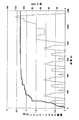
図1は、低温活性後のCO放出物は平らであることを示しており、これは、CSFが加熱された後、フィルター基材の熱容量(thermal mass)が、排ガス温度が変動する際にも、COを転化するための十分な熱を維持することを示唆している。 FIG. 1 shows that the CO emissions after low-temperature activation are flat, which means that after the CSF is heated, the thermal mass of the filter substrate also varies as the exhaust gas temperature varies. , Suggesting maintaining sufficient heat to convert CO.
Claims (38)
前記排気機構が、平均細孔直径が5μm〜40μmであり、多孔率が少なくとも40%であり、バルク体積熱容量が500℃で少なくとも0.50Jcm−3K−1である多孔質材料から製造された粒子状フィルターを備えてなり、
前記フィルターが、前記フィルターの前端部にある区域に配置された、一酸化炭素(CO)、炭化水素(HC)および一酸化窒素(NO)を酸化するためのディーゼル酸化触媒(DOC)を含んでなり、
前記エンジンが、使用中に、十分な酸化窒素(NOx)またはHCを含んでなる排ガスおよび/または前記フィルター中の粒子状物質(PM)を燃焼させるのに十分に高い温度を有する排ガスを連続的または間欠的に供給するエンジン管理手段を備えてなる、エンジン。 A diesel engine having an exhaust mechanism,
The exhaust mechanism was manufactured from a porous material having an average pore diameter of 5 μm to 40 μm, a porosity of at least 40%, and a bulk volume heat capacity of at least 0.50 Jcm −3 K −1 at 500 ° C. With a particulate filter,
The filter includes a diesel oxidation catalyst (DOC) for oxidizing carbon monoxide (CO), hydrocarbons (HC), and nitric oxide (NO) disposed in an area at the front end of the filter. Become
During use, the engine continuously emits exhaust gas comprising sufficient nitric oxide (NO x ) or HC and / or exhaust gas having a sufficiently high temperature to burn particulate matter (PM) in the filter. An engine comprising an engine management means for supplying a motor intermittently or intermittently.
該ハニカムが、入口末端および出口末端と、および前記入口末端から前記出口末端に伸びる複数のセルを有してなり、
前記セルが多孔質の壁を有し、前記セルの総数の一部が、前記入口末端で、前記セルの長さの一部に沿って塞がれており、
前記入口末端で開いている前記セルの残り部分が、前記出口末端で前記セルの長さの一部に沿って塞がれてなり、これにより、
前記入口末端から前記ハニカムの前記セルを通って流れる排ガスは、前記開いたセルの中に流れ込み、前記セルの壁を通り、及び、前記出口末端にある前記開いたセルを通って前記フィルターから排出される、請求項1〜3のいずれか一項に記載のエンジン。 The filter has a honeycomb shape;
The honeycomb has an inlet end and an outlet end, and a plurality of cells extending from the inlet end to the outlet end;
The cell has a porous wall, and a portion of the total number of the cells is plugged along a portion of the length of the cell at the inlet end;
The remaining portion of the cell that is open at the inlet end is blocked along a portion of the length of the cell at the outlet end, thereby
Exhaust gas flowing through the cells of the honeycomb from the inlet end flows into the open cells, passes through the walls of the cells, and exits the filter through the open cells at the outlet end. The engine according to any one of claims 1 to 3.
Applications Claiming Priority (2)
| Application Number | Priority Date | Filing Date | Title |
|---|---|---|---|
| GBGB0304939.2A GB0304939D0 (en) | 2003-03-05 | 2003-03-05 | Light-duty diesel engine and a particulate filter therefor |
| PCT/GB2004/000882 WO2004079167A1 (en) | 2003-03-05 | 2004-03-05 | Diesel engine and a catalysed filter therefor |
Publications (2)
| Publication Number | Publication Date |
|---|---|
| JP2006520264A true JP2006520264A (en) | 2006-09-07 |
| JP2006520264A5 JP2006520264A5 (en) | 2007-04-19 |
Family
ID=9954094
Family Applications (1)
| Application Number | Title | Priority Date | Filing Date |
|---|---|---|---|
| JP2006505908A Pending JP2006520264A (en) | 2003-03-05 | 2004-03-05 | Catalyzed filters for diesel engines and diesel engines |
Country Status (9)
| Country | Link |
|---|---|
| US (1) | US9169753B2 (en) |
| EP (1) | EP1599660B1 (en) |
| JP (1) | JP2006520264A (en) |
| KR (1) | KR101110649B1 (en) |
| CN (1) | CN100443710C (en) |
| CZ (1) | CZ2005554A3 (en) |
| GB (1) | GB0304939D0 (en) |
| MX (1) | MXPA05009590A (en) |
| WO (1) | WO2004079167A1 (en) |
Cited By (7)
| Publication number | Priority date | Publication date | Assignee | Title |
|---|---|---|---|---|
| JP2008272738A (en) * | 2007-03-30 | 2008-11-13 | Ibiden Co Ltd | Honeycomb structure |
| JP2008284542A (en) * | 2007-04-20 | 2008-11-27 | Ibiden Co Ltd | Honeycomb filter |
| JP2011504869A (en) * | 2007-11-27 | 2011-02-17 | コーニング インコーポレイテッド | Microporous low microcracked ceramic honeycomb and method |
| WO2012070386A1 (en) * | 2010-11-24 | 2012-05-31 | 住友化学株式会社 | Honeycomb filter |
| JP2015528868A (en) * | 2012-04-13 | 2015-10-01 | ユミコア・アクチエンゲゼルシャフト・ウント・コムパニー・コマンディットゲゼルシャフトUmicore AG & Co.KG | Pollutant reduction device for gasoline vehicles |
| JP2015534501A (en) * | 2012-09-21 | 2015-12-03 | クラリアント・インターナシヨナル・リミテツド | Method for purification of exhaust gas and regeneration of oxidation catalyst |
| US10344641B2 (en) | 2017-03-09 | 2019-07-09 | Cataler Corporation | Exhaust gas purifying catalyst |
Families Citing this family (33)
| Publication number | Priority date | Publication date | Assignee | Title |
|---|---|---|---|---|
| GB0405015D0 (en) * | 2004-03-05 | 2004-04-07 | Johnson Matthey Plc | Method of loading a monolith with catalyst and/or washcoat |
| JP2007130624A (en) * | 2005-10-14 | 2007-05-31 | Matsushita Electric Ind Co Ltd | Exhaust gas purification filter |
| DE102006035052A1 (en) * | 2005-11-17 | 2007-05-24 | Robert Bosch Gmbh | Filter element and filter for exhaust aftertreatment |
| GB0603898D0 (en) | 2006-02-28 | 2006-04-05 | Johnson Matthey Plc | Exhaust system comprising catalysed soot filter |
| JP5276587B2 (en) * | 2006-06-30 | 2013-08-28 | コーニング インコーポレイテッド | Low microcracked porous ceramic honeycomb and method for producing the same |
| US7685814B2 (en) | 2006-07-12 | 2010-03-30 | Cummins Filtration, Inc. | Systems, apparatuses, and methods of determining plugging or deplugging of a diesel oxidation catalyst device |
| WO2008011146A1 (en) * | 2006-07-21 | 2008-01-24 | Dow Global Technologies Inc. | Improved zone catalyzed soot filter |
| JP5063980B2 (en) * | 2006-10-24 | 2012-10-31 | Dowaエレクトロニクス株式会社 | Composite oxide and filter for exhaust gas purification catalyst |
| US8484953B2 (en) | 2007-06-15 | 2013-07-16 | GM Global Technology Operations LLC | Electrically heated particulate filter using catalyst striping |
| WO2009048994A2 (en) * | 2007-10-12 | 2009-04-16 | Dow Global Technologies Inc. | Improved thermal shock resistant soot filter |
| US9993771B2 (en) | 2007-12-12 | 2018-06-12 | Basf Corporation | Emission treatment catalysts, systems and methods |
| US9863297B2 (en) * | 2007-12-12 | 2018-01-09 | Basf Corporation | Emission treatment system |
| KR100969378B1 (en) * | 2008-03-31 | 2010-07-09 | 현대자동차주식회사 | Apparatus for purifying exhaust gas |
| WO2009122534A1 (en) | 2008-03-31 | 2009-10-08 | イビデン株式会社 | Honeycomb structure |
| US8393140B2 (en) * | 2008-05-02 | 2013-03-12 | GM Global Technology Operations LLC | Passive ammonia-selective catalytic reduction for NOx control in internal combustion engines |
| JP5909191B2 (en) * | 2009-11-20 | 2016-04-26 | ビーエーエスエフ ソシエタス・ヨーロピアBasf Se | Banded catalyst soot filter |
| GB0922194D0 (en) | 2009-12-21 | 2010-02-03 | Johnson Matthey Plc | Improvements in emission control |
| GB201000019D0 (en) | 2010-01-04 | 2010-02-17 | Johnson Matthey Plc | Coating a monolith substrate with catalyst component |
| US8591820B2 (en) * | 2011-03-11 | 2013-11-26 | Corning Incorporated | Honeycomb filters for reducing NOx and particulate matter in diesel engine exhaust |
| US9126182B2 (en) | 2012-01-30 | 2015-09-08 | Basf Corporation | Catalyzed soot filters, systems and methods of treatment |
| EP2832413B1 (en) * | 2012-03-30 | 2018-12-05 | Ibiden Co., Ltd | Honeycomb filter |
| GB201219600D0 (en) | 2012-10-31 | 2012-12-12 | Johnson Matthey Plc | Catalysed soot filter |
| GB201311615D0 (en) | 2013-06-03 | 2013-08-14 | Johnson Matthey Plc | Method of coating a substrate with a catalyst component |
| CN104588651A (en) * | 2014-10-31 | 2015-05-06 | 成都易态科技有限公司 | Flexible multi-hole metal foil and manufacturing method thereof |
| WO2016150465A1 (en) * | 2015-03-20 | 2016-09-29 | Haldor Topsøe A/S | Catalyzed ceramic candle filter and method for cleaning of off- or exhaust gases |
| CN104819034B (en) * | 2015-04-22 | 2017-08-04 | 江苏大学 | A kind of diesel engine EGR system is repeatable to utilize desulfurization particulate filter arrangement |
| US10099212B2 (en) * | 2016-03-15 | 2018-10-16 | Cummins Emission Solutions Inc. | Hydrocarbon storage optimization and coking prevention on an oxidation catalyst |
| KR101818417B1 (en) * | 2016-09-23 | 2018-01-15 | 한국전력공사 | Exhaust gas purification apparatus and method for purifying exhaust gas using the same |
| CN106492876A (en) * | 2016-10-18 | 2017-03-15 | 南京依柯卡特排放技术股份有限公司 | A kind of preparation method of LD-diesel oxidation catalyst |
| CN106492795A (en) * | 2016-10-18 | 2017-03-15 | 南京依柯卡特排放技术股份有限公司 | For exhaust emissions of diesel engine DOC oxidation catalysts and preparation method |
| US11365665B2 (en) * | 2016-10-24 | 2022-06-21 | Ngk Insulators, Ltd. | Porous material, honeycomb structure, and method of producing porous material |
| US11428138B2 (en) * | 2016-10-24 | 2022-08-30 | Ngk Insulators, Ltd. | Porous material, honeycomb structure, and method of producing porous material |
| KR101815015B1 (en) * | 2017-02-23 | 2018-01-08 | 김재수 | Composition for soot-particle reduction |
Citations (6)
| Publication number | Priority date | Publication date | Assignee | Title |
|---|---|---|---|---|
| JPH0333419A (en) * | 1989-06-29 | 1991-02-13 | Mitsubishi Motors Corp | Catalyst converter |
| WO2001012320A1 (en) * | 1999-08-13 | 2001-02-22 | Johnson Matthey Public Limited Company | Catalytic wall-flow filter |
| JP2001207836A (en) * | 2000-01-19 | 2001-08-03 | Toyota Motor Corp | Exhaust emission control device for internal combustion engine |
| WO2001091882A1 (en) * | 2000-06-01 | 2001-12-06 | Corning Incorporated | Cordierite body |
| JP2003154223A (en) * | 2001-07-18 | 2003-05-27 | Ibiden Co Ltd | Filter with catalyst, method for manufacturing the same and exhaust gas control system |
| JP2003161138A (en) * | 2001-11-28 | 2003-06-06 | Isuzu Motors Ltd | Diesel particulate filter |
Family Cites Families (41)
| Publication number | Priority date | Publication date | Assignee | Title |
|---|---|---|---|---|
| US4329162A (en) | 1980-07-03 | 1982-05-11 | Corning Glass Works | Diesel particulate trap |
| DE3101026A1 (en) | 1981-01-15 | 1982-08-26 | Engelhard Kali-Chemie Autocat Gmbh, 3000 Hannover | BIFUNCTIONAL FILTER FOR TREATING EXHAUST GAS |
| DE3232729A1 (en) | 1982-09-03 | 1984-03-08 | Degussa Ag, 6000 Frankfurt | METHOD FOR REDUCING THE IGNITION TEMPERATURE OF DIESEL CARBON FILTERED OUT OF THE EXHAUST GAS FROM DIESEL ENGINES |
| JPS63185425A (en) | 1987-01-28 | 1988-08-01 | Ngk Insulators Ltd | Ceramic honeycomb filter for cleaning exhaust gas |
| DE3815969A1 (en) | 1988-05-10 | 1989-11-23 | Norton Gmbh | DISH BURN CAPSULE |
| US4902487A (en) | 1988-05-13 | 1990-02-20 | Johnson Matthey, Inc. | Treatment of diesel exhaust gases |
| DE3923985C1 (en) | 1989-07-20 | 1990-06-28 | Daimler-Benz Aktiengesellschaft, 7000 Stuttgart, De | |
| CA2097609C (en) | 1991-10-03 | 1999-03-16 | Shinichi Takeshima | Device for purifying exhaust of internal combustion engine |
| DE69328202T2 (en) | 1992-09-28 | 2000-07-20 | Ford Motor Co | Filter element for controlling exhaust gas emissions from internal combustion engines |
| US5492679A (en) | 1993-03-08 | 1996-02-20 | General Motors Corporation | Zeolite/catalyst wall-flow monolith adsorber |
| US5396764A (en) | 1994-02-14 | 1995-03-14 | Ford Motor Company | Spark ignition engine exhaust system |
| JPH08182918A (en) | 1994-12-28 | 1996-07-16 | Kawasaki Heavy Ind Ltd | Fluidized bed denitrification by pulverized carbon and device therefor |
| JP3750178B2 (en) | 1995-04-05 | 2006-03-01 | 株式会社デンソー | Exhaust gas purification filter and manufacturing method thereof |
| JP3899534B2 (en) | 1995-08-14 | 2007-03-28 | トヨタ自動車株式会社 | Exhaust gas purification method for diesel engine |
| JP3387290B2 (en) | 1995-10-02 | 2003-03-17 | トヨタ自動車株式会社 | Exhaust gas purification filter |
| US5878567A (en) * | 1996-01-22 | 1999-03-09 | Ford Global Technologies, Inc. | Closely coupled exhaust catalyst system and engine strategy associated therewith |
| GB9612970D0 (en) | 1996-06-20 | 1996-08-21 | Johnson Matthey Plc | Combatting air pollution |
| JP3446558B2 (en) | 1996-10-03 | 2003-09-16 | 株式会社豊田中央研究所 | Exhaust gas purification filter |
| US6142934A (en) | 1997-04-04 | 2000-11-07 | Welch Allyn, Inc. | Objective lens system for imaging instrument |
| US20030077625A1 (en) | 1997-05-27 | 2003-04-24 | Hutchison James E. | Particles by facile ligand exchange reactions |
| GB9802504D0 (en) | 1998-02-06 | 1998-04-01 | Johnson Matthey Plc | Improvements in emission control |
| GB9805815D0 (en) | 1998-03-19 | 1998-05-13 | Johnson Matthey Plc | Manufacturing process |
| JP2002512880A (en) | 1998-04-28 | 2002-05-08 | エンゲルハード・コーポレーシヨン | Monolith type catalyst and related manufacturing method |
| DE69927718T2 (en) | 1998-11-13 | 2006-07-13 | Engelhard Corp. | CATALYST AND METHOD FOR REDUCING EXHAUST EMISSIONS |
| DE69903066T2 (en) * | 1998-12-05 | 2003-03-13 | Johnson Matthey Plc | IMPROVEMENTS IN EXHAUST GAS PARTICULAR CONTROL |
| US6375910B1 (en) | 1999-04-02 | 2002-04-23 | Engelhard Corporation | Multi-zoned catalytic trap and methods of making and using the same |
| FI107828B (en) | 1999-05-18 | 2001-10-15 | Kemira Metalkat Oy | Systems for cleaning exhaust gases from diesel engines and method for cleaning exhaust gases from diesel engines |
| GB9913331D0 (en) | 1999-06-09 | 1999-08-11 | Johnson Matthey Plc | Treatment of exhaust gas |
| FR2805568B1 (en) * | 2000-02-28 | 2002-05-31 | Peugeot Citroen Automobiles Sa | SYSTEM FOR AIDING THE REGENERATION OF A PARTICLE FILTER INTEGRATED IN AN EXHAUST LINE OF A DIESEL ENGINE OF A MOTOR VEHICLE |
| US6568178B2 (en) * | 2000-03-28 | 2003-05-27 | Toyota Jidosha Kabushiki Kaisha | Device for purifying the exhaust gas of an internal combustion engine |
| US6576579B2 (en) * | 2000-10-03 | 2003-06-10 | Corning Incorporated | Phosphate-based ceramic |
| JP2004535909A (en) | 2000-11-07 | 2004-12-02 | コーニング インコーポレイテッド | Polcite-based ceramic with low CTE |
| JP2002227688A (en) * | 2001-02-01 | 2002-08-14 | Nissan Motor Co Ltd | Exhaust gas purifying device for diesel engine |
| JP2002295298A (en) | 2001-03-29 | 2002-10-09 | Isuzu Motors Ltd | Exhaust emission control system and its recovery control method |
| DE10118327A1 (en) * | 2001-04-12 | 2002-10-17 | Emitec Emissionstechnologie | Diesel exhaust purification system for automobiles, comprises oxidative catalysts converting carbon monoxide, hydrocarbon and nitrogen oxides, followed by particle trap |
| EP1312776A3 (en) * | 2001-11-16 | 2004-05-12 | Isuzu Motors Limited | Exhaust gas purification system |
| US6620751B1 (en) | 2002-03-14 | 2003-09-16 | Corning Incorporated | Strontium feldspar aluminum titanate for high temperature applications |
| EP1515787A4 (en) | 2002-06-26 | 2006-11-29 | Corning Inc | Magnesium aluminum silicate structures for dpf applications |
| US6849181B2 (en) | 2002-07-31 | 2005-02-01 | Corning Incorporated | Mullite-aluminum titanate diesel exhaust filter |
| US7716921B2 (en) * | 2005-09-01 | 2010-05-18 | Gm Global Technology Operations, Inc. | Exhaust particulate filter |
| US20080053070A1 (en) * | 2006-09-01 | 2008-03-06 | Andrew Hatton | Apparatus and method for regenerating a particulate filter with a non-uniformly loaded oxidation catalyst |
-
2003
- 2003-03-05 GB GBGB0304939.2A patent/GB0304939D0/en not_active Ceased
-
2004
- 2004-03-05 CN CNB2004800059334A patent/CN100443710C/en not_active Expired - Lifetime
- 2004-03-05 WO PCT/GB2004/000882 patent/WO2004079167A1/en active Application Filing
- 2004-03-05 MX MXPA05009590A patent/MXPA05009590A/en unknown
- 2004-03-05 CZ CZ20050554A patent/CZ2005554A3/en unknown
- 2004-03-05 US US10/547,834 patent/US9169753B2/en active Active
- 2004-03-05 JP JP2006505908A patent/JP2006520264A/en active Pending
- 2004-03-05 KR KR1020057016546A patent/KR101110649B1/en active IP Right Grant
- 2004-03-05 EP EP04717674.8A patent/EP1599660B1/en not_active Expired - Lifetime
Patent Citations (6)
| Publication number | Priority date | Publication date | Assignee | Title |
|---|---|---|---|---|
| JPH0333419A (en) * | 1989-06-29 | 1991-02-13 | Mitsubishi Motors Corp | Catalyst converter |
| WO2001012320A1 (en) * | 1999-08-13 | 2001-02-22 | Johnson Matthey Public Limited Company | Catalytic wall-flow filter |
| JP2001207836A (en) * | 2000-01-19 | 2001-08-03 | Toyota Motor Corp | Exhaust emission control device for internal combustion engine |
| WO2001091882A1 (en) * | 2000-06-01 | 2001-12-06 | Corning Incorporated | Cordierite body |
| JP2003154223A (en) * | 2001-07-18 | 2003-05-27 | Ibiden Co Ltd | Filter with catalyst, method for manufacturing the same and exhaust gas control system |
| JP2003161138A (en) * | 2001-11-28 | 2003-06-06 | Isuzu Motors Ltd | Diesel particulate filter |
Cited By (9)
| Publication number | Priority date | Publication date | Assignee | Title |
|---|---|---|---|---|
| JP2008272738A (en) * | 2007-03-30 | 2008-11-13 | Ibiden Co Ltd | Honeycomb structure |
| JP2008284542A (en) * | 2007-04-20 | 2008-11-27 | Ibiden Co Ltd | Honeycomb filter |
| JP2011504869A (en) * | 2007-11-27 | 2011-02-17 | コーニング インコーポレイテッド | Microporous low microcracked ceramic honeycomb and method |
| WO2012070386A1 (en) * | 2010-11-24 | 2012-05-31 | 住友化学株式会社 | Honeycomb filter |
| JP2015528868A (en) * | 2012-04-13 | 2015-10-01 | ユミコア・アクチエンゲゼルシャフト・ウント・コムパニー・コマンディットゲゼルシャフトUmicore AG & Co.KG | Pollutant reduction device for gasoline vehicles |
| JP2020008022A (en) * | 2012-04-13 | 2020-01-16 | ユミコア・アクチエンゲゼルシャフト・ウント・コムパニー・コマンディットゲゼルシャフトUmicore AG & Co.KG | Contaminant reduction device for gasoline automobile |
| JP2015534501A (en) * | 2012-09-21 | 2015-12-03 | クラリアント・インターナシヨナル・リミテツド | Method for purification of exhaust gas and regeneration of oxidation catalyst |
| US9815023B2 (en) | 2012-09-21 | 2017-11-14 | Clariant International Ltd. | Method for purifying exhaust gas and for regenerating an oxidation catalyst |
| US10344641B2 (en) | 2017-03-09 | 2019-07-09 | Cataler Corporation | Exhaust gas purifying catalyst |
Also Published As
| Publication number | Publication date |
|---|---|
| CN1809686A (en) | 2006-07-26 |
| US9169753B2 (en) | 2015-10-27 |
| MXPA05009590A (en) | 2005-11-04 |
| GB0304939D0 (en) | 2003-04-09 |
| KR101110649B1 (en) | 2012-02-27 |
| EP1599660B1 (en) | 2018-05-23 |
| EP1599660A1 (en) | 2005-11-30 |
| US20070028604A1 (en) | 2007-02-08 |
| CZ2005554A3 (en) | 2006-02-15 |
| WO2004079167A1 (en) | 2004-09-16 |
| KR20050113636A (en) | 2005-12-02 |
| CN100443710C (en) | 2008-12-17 |
Similar Documents
| Publication | Publication Date | Title |
|---|---|---|
| JP2006520264A (en) | Catalyzed filters for diesel engines and diesel engines | |
| EP1437491B1 (en) | Filter catalyst for purifying exhaust gases | |
| JP5447757B2 (en) | Catalyst coated particle filter, process for its production and use thereof | |
| JP4393039B2 (en) | Filter with catalyst, method for manufacturing the same, and exhaust gas purification system | |
| US7465690B2 (en) | Methods for making a catalytic element, the catalytic element made therefrom, and catalyzed particulate filters | |
| US6916450B2 (en) | Exhaust gas purifying system and method | |
| EP1371826B1 (en) | Filter catalyst for purifying exhaust gases | |
| KR101834022B1 (en) | Gasoline engine emissions treatment systems having gasoline particulate filters | |
| EP1679119B1 (en) | Method of production of a filter catalyst for exhaust gas purification of a diesel engine | |
| JP5193437B2 (en) | Exhaust gas purification catalyst | |
| JP4556587B2 (en) | Exhaust gas purification device | |
| WO2007052817A1 (en) | Exhaust gas purification apparatus | |
| JP2009285605A (en) | Catalyst for cleaning exhaust gas | |
| JP4006645B2 (en) | Exhaust gas purification device | |
| JP4174976B2 (en) | Exhaust purification device and method for manufacturing the same | |
| JP3844350B2 (en) | Light oil combustion oxidation catalyst | |
| JP2008151100A (en) | Exhaust emission control device | |
| JP4239864B2 (en) | Diesel exhaust gas purification device | |
| JP2006231116A (en) | Exhaust gas-cleaning filter catalyst | |
| JP2007117954A (en) | Catalyst for cleaning exhaust gas from diesel engine | |
| JP4218559B2 (en) | Diesel exhaust gas purification device | |
| CN101374586A (en) | Exhaust gas-purifying catalyst | |
| JP2004169636A (en) | Diesel particulate filter and its manufacturing method |
Legal Events
| Date | Code | Title | Description |
|---|---|---|---|
| A521 | Request for written amendment filed |
Free format text: JAPANESE INTERMEDIATE CODE: A523 Effective date: 20070305 |
|
| A621 | Written request for application examination |
Free format text: JAPANESE INTERMEDIATE CODE: A621 Effective date: 20070305 |
|
| A131 | Notification of reasons for refusal |
Free format text: JAPANESE INTERMEDIATE CODE: A131 Effective date: 20100910 |
|
| A601 | Written request for extension of time |
Free format text: JAPANESE INTERMEDIATE CODE: A601 Effective date: 20101209 |
|
| A602 | Written permission of extension of time |
Free format text: JAPANESE INTERMEDIATE CODE: A602 Effective date: 20101216 |
|
| A601 | Written request for extension of time |
Free format text: JAPANESE INTERMEDIATE CODE: A601 Effective date: 20110107 |
|
| A602 | Written permission of extension of time |
Free format text: JAPANESE INTERMEDIATE CODE: A602 Effective date: 20110117 |
|
| A601 | Written request for extension of time |
Free format text: JAPANESE INTERMEDIATE CODE: A601 Effective date: 20110209 |
|
| A602 | Written permission of extension of time |
Free format text: JAPANESE INTERMEDIATE CODE: A602 Effective date: 20110217 |
|
| A02 | Decision of refusal |
Free format text: JAPANESE INTERMEDIATE CODE: A02 Effective date: 20120104 |
|
| A521 | Request for written amendment filed |
Free format text: JAPANESE INTERMEDIATE CODE: A523 Effective date: 20120507 |
|
| A911 | Transfer to examiner for re-examination before appeal (zenchi) |
Free format text: JAPANESE INTERMEDIATE CODE: A911 Effective date: 20120514 |
|
| A912 | Re-examination (zenchi) completed and case transferred to appeal board |
Free format text: JAPANESE INTERMEDIATE CODE: A912 Effective date: 20120727 |
|
| A601 | Written request for extension of time |
Free format text: JAPANESE INTERMEDIATE CODE: A601 Effective date: 20121206 |
|
| A602 | Written permission of extension of time |
Free format text: JAPANESE INTERMEDIATE CODE: A602 Effective date: 20121211 |
|
| A601 | Written request for extension of time |
Free format text: JAPANESE INTERMEDIATE CODE: A601 Effective date: 20130107 |
|
| A602 | Written permission of extension of time |
Free format text: JAPANESE INTERMEDIATE CODE: A602 Effective date: 20130110 |
|
| RD03 | Notification of appointment of power of attorney |
Free format text: JAPANESE INTERMEDIATE CODE: A7423 Effective date: 20130125 |
|
| A601 | Written request for extension of time |
Free format text: JAPANESE INTERMEDIATE CODE: A601 Effective date: 20130201 |
|
| A602 | Written permission of extension of time |
Free format text: JAPANESE INTERMEDIATE CODE: A602 Effective date: 20130208 |
|
| RD04 | Notification of resignation of power of attorney |
Free format text: JAPANESE INTERMEDIATE CODE: A7424 Effective date: 20130214 |