JP6231908B2 - Plugged honeycomb structure - Google Patents
Plugged honeycomb structure Download PDFInfo
- Publication number
- JP6231908B2 JP6231908B2 JP2014052418A JP2014052418A JP6231908B2 JP 6231908 B2 JP6231908 B2 JP 6231908B2 JP 2014052418 A JP2014052418 A JP 2014052418A JP 2014052418 A JP2014052418 A JP 2014052418A JP 6231908 B2 JP6231908 B2 JP 6231908B2
- Authority
- JP
- Japan
- Prior art keywords
- honeycomb structure
- porous body
- plugged honeycomb
- mass
- glass
- Prior art date
- Legal status (The legal status is an assumption and is not a legal conclusion. Google has not performed a legal analysis and makes no representation as to the accuracy of the status listed.)
- Expired - Fee Related
Links
Images
Classifications
-
- F—MECHANICAL ENGINEERING; LIGHTING; HEATING; WEAPONS; BLASTING
- F01—MACHINES OR ENGINES IN GENERAL; ENGINE PLANTS IN GENERAL; STEAM ENGINES
- F01N—GAS-FLOW SILENCERS OR EXHAUST APPARATUS FOR MACHINES OR ENGINES IN GENERAL; GAS-FLOW SILENCERS OR EXHAUST APPARATUS FOR INTERNAL-COMBUSTION ENGINES
- F01N3/00—Exhaust or silencing apparatus having means for purifying, rendering innocuous, or otherwise treating exhaust
- F01N3/02—Exhaust or silencing apparatus having means for purifying, rendering innocuous, or otherwise treating exhaust for cooling, or for removing solid constituents of, exhaust
- F01N3/021—Exhaust or silencing apparatus having means for purifying, rendering innocuous, or otherwise treating exhaust for cooling, or for removing solid constituents of, exhaust by means of filters
- F01N3/022—Exhaust or silencing apparatus having means for purifying, rendering innocuous, or otherwise treating exhaust for cooling, or for removing solid constituents of, exhaust by means of filters characterised by specially adapted filtering structure, e.g. honeycomb, mesh or fibrous
- F01N3/0222—Exhaust or silencing apparatus having means for purifying, rendering innocuous, or otherwise treating exhaust for cooling, or for removing solid constituents of, exhaust by means of filters characterised by specially adapted filtering structure, e.g. honeycomb, mesh or fibrous the structure being monolithic, e.g. honeycombs
-
- B—PERFORMING OPERATIONS; TRANSPORTING
- B01—PHYSICAL OR CHEMICAL PROCESSES OR APPARATUS IN GENERAL
- B01D—SEPARATION
- B01D46/00—Filters or filtering processes specially modified for separating dispersed particles from gases or vapours
- B01D46/24—Particle separators, e.g. dust precipitators, using rigid hollow filter bodies
- B01D46/2403—Particle separators, e.g. dust precipitators, using rigid hollow filter bodies characterised by the physical shape or structure of the filtering element
- B01D46/2418—Honeycomb filters
- B01D46/2425—Honeycomb filters characterized by parameters related to the physical properties of the honeycomb structure material
- B01D46/24494—Thermal expansion coefficient, heat capacity or thermal conductivity
-
- B—PERFORMING OPERATIONS; TRANSPORTING
- B01—PHYSICAL OR CHEMICAL PROCESSES OR APPARATUS IN GENERAL
- B01D—SEPARATION
- B01D46/00—Filters or filtering processes specially modified for separating dispersed particles from gases or vapours
- B01D46/24—Particle separators, e.g. dust precipitators, using rigid hollow filter bodies
- B01D46/2403—Particle separators, e.g. dust precipitators, using rigid hollow filter bodies characterised by the physical shape or structure of the filtering element
- B01D46/2418—Honeycomb filters
- B01D46/2425—Honeycomb filters characterized by parameters related to the physical properties of the honeycomb structure material
- B01D46/2429—Honeycomb filters characterized by parameters related to the physical properties of the honeycomb structure material of the honeycomb walls or cells
-
- B—PERFORMING OPERATIONS; TRANSPORTING
- B01—PHYSICAL OR CHEMICAL PROCESSES OR APPARATUS IN GENERAL
- B01D—SEPARATION
- B01D46/00—Filters or filtering processes specially modified for separating dispersed particles from gases or vapours
- B01D46/24—Particle separators, e.g. dust precipitators, using rigid hollow filter bodies
- B01D46/2403—Particle separators, e.g. dust precipitators, using rigid hollow filter bodies characterised by the physical shape or structure of the filtering element
- B01D46/2418—Honeycomb filters
- B01D46/2425—Honeycomb filters characterized by parameters related to the physical properties of the honeycomb structure material
- B01D46/24491—Porosity
-
- B—PERFORMING OPERATIONS; TRANSPORTING
- B01—PHYSICAL OR CHEMICAL PROCESSES OR APPARATUS IN GENERAL
- B01D—SEPARATION
- B01D46/00—Filters or filtering processes specially modified for separating dispersed particles from gases or vapours
- B01D46/24—Particle separators, e.g. dust precipitators, using rigid hollow filter bodies
- B01D46/2403—Particle separators, e.g. dust precipitators, using rigid hollow filter bodies characterised by the physical shape or structure of the filtering element
- B01D46/2418—Honeycomb filters
- B01D46/2425—Honeycomb filters characterized by parameters related to the physical properties of the honeycomb structure material
- B01D46/24492—Pore diameter
-
- B—PERFORMING OPERATIONS; TRANSPORTING
- B01—PHYSICAL OR CHEMICAL PROCESSES OR APPARATUS IN GENERAL
- B01D—SEPARATION
- B01D46/00—Filters or filtering processes specially modified for separating dispersed particles from gases or vapours
- B01D46/24—Particle separators, e.g. dust precipitators, using rigid hollow filter bodies
- B01D46/2403—Particle separators, e.g. dust precipitators, using rigid hollow filter bodies characterised by the physical shape or structure of the filtering element
- B01D46/2418—Honeycomb filters
- B01D46/2451—Honeycomb filters characterized by the geometrical structure, shape, pattern or configuration or parameters related to the geometry of the structure
- B01D46/2476—Monolithic structures
-
- B—PERFORMING OPERATIONS; TRANSPORTING
- B01—PHYSICAL OR CHEMICAL PROCESSES OR APPARATUS IN GENERAL
- B01D—SEPARATION
- B01D46/00—Filters or filtering processes specially modified for separating dispersed particles from gases or vapours
- B01D46/24—Particle separators, e.g. dust precipitators, using rigid hollow filter bodies
- B01D46/2403—Particle separators, e.g. dust precipitators, using rigid hollow filter bodies characterised by the physical shape or structure of the filtering element
- B01D46/2418—Honeycomb filters
- B01D46/2451—Honeycomb filters characterized by the geometrical structure, shape, pattern or configuration or parameters related to the geometry of the structure
- B01D46/2478—Structures comprising honeycomb segments
-
- B—PERFORMING OPERATIONS; TRANSPORTING
- B01—PHYSICAL OR CHEMICAL PROCESSES OR APPARATUS IN GENERAL
- B01J—CHEMICAL OR PHYSICAL PROCESSES, e.g. CATALYSIS OR COLLOID CHEMISTRY; THEIR RELEVANT APPARATUS
- B01J21/00—Catalysts comprising the elements, oxides, or hydroxides of magnesium, boron, aluminium, carbon, silicon, titanium, zirconium, or hafnium
- B01J21/12—Silica and alumina
-
- B—PERFORMING OPERATIONS; TRANSPORTING
- B01—PHYSICAL OR CHEMICAL PROCESSES OR APPARATUS IN GENERAL
- B01J—CHEMICAL OR PHYSICAL PROCESSES, e.g. CATALYSIS OR COLLOID CHEMISTRY; THEIR RELEVANT APPARATUS
- B01J35/00—Catalysts, in general, characterised by their form or physical properties
- B01J35/50—Catalysts, in general, characterised by their form or physical properties characterised by their shape or configuration
- B01J35/56—Foraminous structures having flow-through passages or channels, e.g. grids or three-dimensional [3D] monoliths
- B01J35/57—Honeycombs
-
- B—PERFORMING OPERATIONS; TRANSPORTING
- B32—LAYERED PRODUCTS
- B32B—LAYERED PRODUCTS, i.e. PRODUCTS BUILT-UP OF STRATA OF FLAT OR NON-FLAT, e.g. CELLULAR OR HONEYCOMB, FORM
- B32B3/00—Layered products comprising a layer with external or internal discontinuities or unevennesses, or a layer of non-planar shape; Layered products comprising a layer having particular features of form
- B32B3/10—Layered products comprising a layer with external or internal discontinuities or unevennesses, or a layer of non-planar shape; Layered products comprising a layer having particular features of form characterised by a discontinuous layer, i.e. formed of separate pieces of material
- B32B3/12—Layered products comprising a layer with external or internal discontinuities or unevennesses, or a layer of non-planar shape; Layered products comprising a layer having particular features of form characterised by a discontinuous layer, i.e. formed of separate pieces of material characterised by a layer of regularly- arranged cells, e.g. a honeycomb structure
-
- C—CHEMISTRY; METALLURGY
- C04—CEMENTS; CONCRETE; ARTIFICIAL STONE; CERAMICS; REFRACTORIES
- C04B—LIME, MAGNESIA; SLAG; CEMENTS; COMPOSITIONS THEREOF, e.g. MORTARS, CONCRETE OR LIKE BUILDING MATERIALS; ARTIFICIAL STONE; CERAMICS; REFRACTORIES; TREATMENT OF NATURAL STONE
- C04B35/00—Shaped ceramic products characterised by their composition; Ceramics compositions; Processing powders of inorganic compounds preparatory to the manufacturing of ceramic products
- C04B35/01—Shaped ceramic products characterised by their composition; Ceramics compositions; Processing powders of inorganic compounds preparatory to the manufacturing of ceramic products based on oxide ceramics
- C04B35/10—Shaped ceramic products characterised by their composition; Ceramics compositions; Processing powders of inorganic compounds preparatory to the manufacturing of ceramic products based on oxide ceramics based on aluminium oxide
- C04B35/111—Fine ceramics
- C04B35/117—Composites
-
- C—CHEMISTRY; METALLURGY
- C04—CEMENTS; CONCRETE; ARTIFICIAL STONE; CERAMICS; REFRACTORIES
- C04B—LIME, MAGNESIA; SLAG; CEMENTS; COMPOSITIONS THEREOF, e.g. MORTARS, CONCRETE OR LIKE BUILDING MATERIALS; ARTIFICIAL STONE; CERAMICS; REFRACTORIES; TREATMENT OF NATURAL STONE
- C04B35/00—Shaped ceramic products characterised by their composition; Ceramics compositions; Processing powders of inorganic compounds preparatory to the manufacturing of ceramic products
- C04B35/622—Forming processes; Processing powders of inorganic compounds preparatory to the manufacturing of ceramic products
- C04B35/626—Preparing or treating the powders individually or as batches ; preparing or treating macroscopic reinforcing agents for ceramic products, e.g. fibres; mechanical aspects section B
- C04B35/63—Preparing or treating the powders individually or as batches ; preparing or treating macroscopic reinforcing agents for ceramic products, e.g. fibres; mechanical aspects section B using additives specially adapted for forming the products, e.g.. binder binders
- C04B35/632—Organic additives
- C04B35/636—Polysaccharides or derivatives thereof
- C04B35/6365—Cellulose or derivatives thereof
-
- C—CHEMISTRY; METALLURGY
- C04—CEMENTS; CONCRETE; ARTIFICIAL STONE; CERAMICS; REFRACTORIES
- C04B—LIME, MAGNESIA; SLAG; CEMENTS; COMPOSITIONS THEREOF, e.g. MORTARS, CONCRETE OR LIKE BUILDING MATERIALS; ARTIFICIAL STONE; CERAMICS; REFRACTORIES; TREATMENT OF NATURAL STONE
- C04B35/00—Shaped ceramic products characterised by their composition; Ceramics compositions; Processing powders of inorganic compounds preparatory to the manufacturing of ceramic products
- C04B35/622—Forming processes; Processing powders of inorganic compounds preparatory to the manufacturing of ceramic products
- C04B35/626—Preparing or treating the powders individually or as batches ; preparing or treating macroscopic reinforcing agents for ceramic products, e.g. fibres; mechanical aspects section B
- C04B35/63—Preparing or treating the powders individually or as batches ; preparing or treating macroscopic reinforcing agents for ceramic products, e.g. fibres; mechanical aspects section B using additives specially adapted for forming the products, e.g.. binder binders
- C04B35/638—Removal thereof
-
- C—CHEMISTRY; METALLURGY
- C04—CEMENTS; CONCRETE; ARTIFICIAL STONE; CERAMICS; REFRACTORIES
- C04B—LIME, MAGNESIA; SLAG; CEMENTS; COMPOSITIONS THEREOF, e.g. MORTARS, CONCRETE OR LIKE BUILDING MATERIALS; ARTIFICIAL STONE; CERAMICS; REFRACTORIES; TREATMENT OF NATURAL STONE
- C04B37/00—Joining burned ceramic articles with other burned ceramic articles or other articles by heating
- C04B37/003—Joining burned ceramic articles with other burned ceramic articles or other articles by heating by means of an interlayer consisting of a combination of materials selected from glass, or ceramic material with metals, metal oxides or metal salts
-
- C—CHEMISTRY; METALLURGY
- C04—CEMENTS; CONCRETE; ARTIFICIAL STONE; CERAMICS; REFRACTORIES
- C04B—LIME, MAGNESIA; SLAG; CEMENTS; COMPOSITIONS THEREOF, e.g. MORTARS, CONCRETE OR LIKE BUILDING MATERIALS; ARTIFICIAL STONE; CERAMICS; REFRACTORIES; TREATMENT OF NATURAL STONE
- C04B38/00—Porous mortars, concrete, artificial stone or ceramic ware; Preparation thereof
- C04B38/0006—Honeycomb structures
-
- F—MECHANICAL ENGINEERING; LIGHTING; HEATING; WEAPONS; BLASTING
- F01—MACHINES OR ENGINES IN GENERAL; ENGINE PLANTS IN GENERAL; STEAM ENGINES
- F01N—GAS-FLOW SILENCERS OR EXHAUST APPARATUS FOR MACHINES OR ENGINES IN GENERAL; GAS-FLOW SILENCERS OR EXHAUST APPARATUS FOR INTERNAL-COMBUSTION ENGINES
- F01N3/00—Exhaust or silencing apparatus having means for purifying, rendering innocuous, or otherwise treating exhaust
- F01N3/08—Exhaust or silencing apparatus having means for purifying, rendering innocuous, or otherwise treating exhaust for rendering innocuous
- F01N3/10—Exhaust or silencing apparatus having means for purifying, rendering innocuous, or otherwise treating exhaust for rendering innocuous by thermal or catalytic conversion of noxious components of exhaust
- F01N3/24—Exhaust or silencing apparatus having means for purifying, rendering innocuous, or otherwise treating exhaust for rendering innocuous by thermal or catalytic conversion of noxious components of exhaust characterised by constructional aspects of converting apparatus
- F01N3/28—Construction of catalytic reactors
- F01N3/2803—Construction of catalytic reactors characterised by structure, by material or by manufacturing of catalyst support
- F01N3/2825—Ceramics
- F01N3/2828—Ceramic multi-channel monoliths, e.g. honeycombs
-
- B—PERFORMING OPERATIONS; TRANSPORTING
- B01—PHYSICAL OR CHEMICAL PROCESSES OR APPARATUS IN GENERAL
- B01J—CHEMICAL OR PHYSICAL PROCESSES, e.g. CATALYSIS OR COLLOID CHEMISTRY; THEIR RELEVANT APPARATUS
- B01J21/00—Catalysts comprising the elements, oxides, or hydroxides of magnesium, boron, aluminium, carbon, silicon, titanium, zirconium, or hafnium
- B01J21/16—Clays or other mineral silicates
-
- B—PERFORMING OPERATIONS; TRANSPORTING
- B01—PHYSICAL OR CHEMICAL PROCESSES OR APPARATUS IN GENERAL
- B01J—CHEMICAL OR PHYSICAL PROCESSES, e.g. CATALYSIS OR COLLOID CHEMISTRY; THEIR RELEVANT APPARATUS
- B01J2235/00—Indexing scheme associated with group B01J35/00, related to the analysis techniques used to determine the catalysts form or properties
- B01J2235/15—X-ray diffraction
-
- B—PERFORMING OPERATIONS; TRANSPORTING
- B01—PHYSICAL OR CHEMICAL PROCESSES OR APPARATUS IN GENERAL
- B01J—CHEMICAL OR PHYSICAL PROCESSES, e.g. CATALYSIS OR COLLOID CHEMISTRY; THEIR RELEVANT APPARATUS
- B01J2235/00—Indexing scheme associated with group B01J35/00, related to the analysis techniques used to determine the catalysts form or properties
- B01J2235/30—Scanning electron microscopy; Transmission electron microscopy
-
- B—PERFORMING OPERATIONS; TRANSPORTING
- B01—PHYSICAL OR CHEMICAL PROCESSES OR APPARATUS IN GENERAL
- B01J—CHEMICAL OR PHYSICAL PROCESSES, e.g. CATALYSIS OR COLLOID CHEMISTRY; THEIR RELEVANT APPARATUS
- B01J35/00—Catalysts, in general, characterised by their form or physical properties
- B01J35/30—Catalysts, in general, characterised by their form or physical properties characterised by their physical properties
- B01J35/31—Density
-
- C—CHEMISTRY; METALLURGY
- C04—CEMENTS; CONCRETE; ARTIFICIAL STONE; CERAMICS; REFRACTORIES
- C04B—LIME, MAGNESIA; SLAG; CEMENTS; COMPOSITIONS THEREOF, e.g. MORTARS, CONCRETE OR LIKE BUILDING MATERIALS; ARTIFICIAL STONE; CERAMICS; REFRACTORIES; TREATMENT OF NATURAL STONE
- C04B2111/00—Mortars, concrete or artificial stone or mixtures to prepare them, characterised by specific function, property or use
- C04B2111/00474—Uses not provided for elsewhere in C04B2111/00
- C04B2111/00793—Uses not provided for elsewhere in C04B2111/00 as filters or diaphragms
-
- C—CHEMISTRY; METALLURGY
- C04—CEMENTS; CONCRETE; ARTIFICIAL STONE; CERAMICS; REFRACTORIES
- C04B—LIME, MAGNESIA; SLAG; CEMENTS; COMPOSITIONS THEREOF, e.g. MORTARS, CONCRETE OR LIKE BUILDING MATERIALS; ARTIFICIAL STONE; CERAMICS; REFRACTORIES; TREATMENT OF NATURAL STONE
- C04B2111/00—Mortars, concrete or artificial stone or mixtures to prepare them, characterised by specific function, property or use
- C04B2111/00474—Uses not provided for elsewhere in C04B2111/00
- C04B2111/0081—Uses not provided for elsewhere in C04B2111/00 as catalysts or catalyst carriers
-
- C—CHEMISTRY; METALLURGY
- C04—CEMENTS; CONCRETE; ARTIFICIAL STONE; CERAMICS; REFRACTORIES
- C04B—LIME, MAGNESIA; SLAG; CEMENTS; COMPOSITIONS THEREOF, e.g. MORTARS, CONCRETE OR LIKE BUILDING MATERIALS; ARTIFICIAL STONE; CERAMICS; REFRACTORIES; TREATMENT OF NATURAL STONE
- C04B2201/00—Mortars, concrete or artificial stone characterised by specific physical values
- C04B2201/30—Mortars, concrete or artificial stone characterised by specific physical values for heat transfer properties such as thermal insulation values, e.g. R-values
-
- C—CHEMISTRY; METALLURGY
- C04—CEMENTS; CONCRETE; ARTIFICIAL STONE; CERAMICS; REFRACTORIES
- C04B—LIME, MAGNESIA; SLAG; CEMENTS; COMPOSITIONS THEREOF, e.g. MORTARS, CONCRETE OR LIKE BUILDING MATERIALS; ARTIFICIAL STONE; CERAMICS; REFRACTORIES; TREATMENT OF NATURAL STONE
- C04B2235/00—Aspects relating to ceramic starting mixtures or sintered ceramic products
- C04B2235/02—Composition of constituents of the starting material or of secondary phases of the final product
- C04B2235/30—Constituents and secondary phases not being of a fibrous nature
- C04B2235/32—Metal oxides, mixed metal oxides, or oxide-forming salts thereof, e.g. carbonates, nitrates, (oxy)hydroxides, chlorides
- C04B2235/3217—Aluminum oxide or oxide forming salts thereof, e.g. bauxite, alpha-alumina
-
- C—CHEMISTRY; METALLURGY
- C04—CEMENTS; CONCRETE; ARTIFICIAL STONE; CERAMICS; REFRACTORIES
- C04B—LIME, MAGNESIA; SLAG; CEMENTS; COMPOSITIONS THEREOF, e.g. MORTARS, CONCRETE OR LIKE BUILDING MATERIALS; ARTIFICIAL STONE; CERAMICS; REFRACTORIES; TREATMENT OF NATURAL STONE
- C04B2235/00—Aspects relating to ceramic starting mixtures or sintered ceramic products
- C04B2235/02—Composition of constituents of the starting material or of secondary phases of the final product
- C04B2235/30—Constituents and secondary phases not being of a fibrous nature
- C04B2235/32—Metal oxides, mixed metal oxides, or oxide-forming salts thereof, e.g. carbonates, nitrates, (oxy)hydroxides, chlorides
- C04B2235/3231—Refractory metal oxides, their mixed metal oxides, or oxide-forming salts thereof
- C04B2235/3232—Titanium oxides or titanates, e.g. rutile or anatase
- C04B2235/3234—Titanates, not containing zirconia
-
- C—CHEMISTRY; METALLURGY
- C04—CEMENTS; CONCRETE; ARTIFICIAL STONE; CERAMICS; REFRACTORIES
- C04B—LIME, MAGNESIA; SLAG; CEMENTS; COMPOSITIONS THEREOF, e.g. MORTARS, CONCRETE OR LIKE BUILDING MATERIALS; ARTIFICIAL STONE; CERAMICS; REFRACTORIES; TREATMENT OF NATURAL STONE
- C04B2235/00—Aspects relating to ceramic starting mixtures or sintered ceramic products
- C04B2235/02—Composition of constituents of the starting material or of secondary phases of the final product
- C04B2235/30—Constituents and secondary phases not being of a fibrous nature
- C04B2235/34—Non-metal oxides, non-metal mixed oxides, or salts thereof that form the non-metal oxides upon heating, e.g. carbonates, nitrates, (oxy)hydroxides, chlorides
- C04B2235/3427—Silicates other than clay, e.g. water glass
- C04B2235/3463—Alumino-silicates other than clay, e.g. mullite
- C04B2235/3472—Alkali metal alumino-silicates other than clay, e.g. spodumene, alkali feldspars such as albite or orthoclase, micas such as muscovite, zeolites such as natrolite
-
- C—CHEMISTRY; METALLURGY
- C04—CEMENTS; CONCRETE; ARTIFICIAL STONE; CERAMICS; REFRACTORIES
- C04B—LIME, MAGNESIA; SLAG; CEMENTS; COMPOSITIONS THEREOF, e.g. MORTARS, CONCRETE OR LIKE BUILDING MATERIALS; ARTIFICIAL STONE; CERAMICS; REFRACTORIES; TREATMENT OF NATURAL STONE
- C04B2235/00—Aspects relating to ceramic starting mixtures or sintered ceramic products
- C04B2235/02—Composition of constituents of the starting material or of secondary phases of the final product
- C04B2235/30—Constituents and secondary phases not being of a fibrous nature
- C04B2235/34—Non-metal oxides, non-metal mixed oxides, or salts thereof that form the non-metal oxides upon heating, e.g. carbonates, nitrates, (oxy)hydroxides, chlorides
- C04B2235/349—Clays, e.g. bentonites, smectites such as montmorillonite, vermiculites or kaolines, e.g. illite, talc or sepiolite
-
- C—CHEMISTRY; METALLURGY
- C04—CEMENTS; CONCRETE; ARTIFICIAL STONE; CERAMICS; REFRACTORIES
- C04B—LIME, MAGNESIA; SLAG; CEMENTS; COMPOSITIONS THEREOF, e.g. MORTARS, CONCRETE OR LIKE BUILDING MATERIALS; ARTIFICIAL STONE; CERAMICS; REFRACTORIES; TREATMENT OF NATURAL STONE
- C04B2235/00—Aspects relating to ceramic starting mixtures or sintered ceramic products
- C04B2235/02—Composition of constituents of the starting material or of secondary phases of the final product
- C04B2235/30—Constituents and secondary phases not being of a fibrous nature
- C04B2235/36—Glass starting materials for making ceramics, e.g. silica glass
-
- C—CHEMISTRY; METALLURGY
- C04—CEMENTS; CONCRETE; ARTIFICIAL STONE; CERAMICS; REFRACTORIES
- C04B—LIME, MAGNESIA; SLAG; CEMENTS; COMPOSITIONS THEREOF, e.g. MORTARS, CONCRETE OR LIKE BUILDING MATERIALS; ARTIFICIAL STONE; CERAMICS; REFRACTORIES; TREATMENT OF NATURAL STONE
- C04B2235/00—Aspects relating to ceramic starting mixtures or sintered ceramic products
- C04B2235/02—Composition of constituents of the starting material or of secondary phases of the final product
- C04B2235/50—Constituents or additives of the starting mixture chosen for their shape or used because of their shape or their physical appearance
- C04B2235/54—Particle size related information
- C04B2235/5418—Particle size related information expressed by the size of the particles or aggregates thereof
- C04B2235/5436—Particle size related information expressed by the size of the particles or aggregates thereof micrometer sized, i.e. from 1 to 100 micron
-
- C—CHEMISTRY; METALLURGY
- C04—CEMENTS; CONCRETE; ARTIFICIAL STONE; CERAMICS; REFRACTORIES
- C04B—LIME, MAGNESIA; SLAG; CEMENTS; COMPOSITIONS THEREOF, e.g. MORTARS, CONCRETE OR LIKE BUILDING MATERIALS; ARTIFICIAL STONE; CERAMICS; REFRACTORIES; TREATMENT OF NATURAL STONE
- C04B2235/00—Aspects relating to ceramic starting mixtures or sintered ceramic products
- C04B2235/02—Composition of constituents of the starting material or of secondary phases of the final product
- C04B2235/50—Constituents or additives of the starting mixture chosen for their shape or used because of their shape or their physical appearance
- C04B2235/54—Particle size related information
- C04B2235/5418—Particle size related information expressed by the size of the particles or aggregates thereof
- C04B2235/5445—Particle size related information expressed by the size of the particles or aggregates thereof submicron sized, i.e. from 0,1 to 1 micron
-
- C—CHEMISTRY; METALLURGY
- C04—CEMENTS; CONCRETE; ARTIFICIAL STONE; CERAMICS; REFRACTORIES
- C04B—LIME, MAGNESIA; SLAG; CEMENTS; COMPOSITIONS THEREOF, e.g. MORTARS, CONCRETE OR LIKE BUILDING MATERIALS; ARTIFICIAL STONE; CERAMICS; REFRACTORIES; TREATMENT OF NATURAL STONE
- C04B2235/00—Aspects relating to ceramic starting mixtures or sintered ceramic products
- C04B2235/60—Aspects relating to the preparation, properties or mechanical treatment of green bodies or pre-forms
- C04B2235/602—Making the green bodies or pre-forms by moulding
- C04B2235/6021—Extrusion moulding
-
- C—CHEMISTRY; METALLURGY
- C04—CEMENTS; CONCRETE; ARTIFICIAL STONE; CERAMICS; REFRACTORIES
- C04B—LIME, MAGNESIA; SLAG; CEMENTS; COMPOSITIONS THEREOF, e.g. MORTARS, CONCRETE OR LIKE BUILDING MATERIALS; ARTIFICIAL STONE; CERAMICS; REFRACTORIES; TREATMENT OF NATURAL STONE
- C04B2235/00—Aspects relating to ceramic starting mixtures or sintered ceramic products
- C04B2235/60—Aspects relating to the preparation, properties or mechanical treatment of green bodies or pre-forms
- C04B2235/606—Drying
-
- C—CHEMISTRY; METALLURGY
- C04—CEMENTS; CONCRETE; ARTIFICIAL STONE; CERAMICS; REFRACTORIES
- C04B—LIME, MAGNESIA; SLAG; CEMENTS; COMPOSITIONS THEREOF, e.g. MORTARS, CONCRETE OR LIKE BUILDING MATERIALS; ARTIFICIAL STONE; CERAMICS; REFRACTORIES; TREATMENT OF NATURAL STONE
- C04B2235/00—Aspects relating to ceramic starting mixtures or sintered ceramic products
- C04B2235/70—Aspects relating to sintered or melt-casted ceramic products
- C04B2235/74—Physical characteristics
- C04B2235/76—Crystal structural characteristics, e.g. symmetry
-
- C—CHEMISTRY; METALLURGY
- C04—CEMENTS; CONCRETE; ARTIFICIAL STONE; CERAMICS; REFRACTORIES
- C04B—LIME, MAGNESIA; SLAG; CEMENTS; COMPOSITIONS THEREOF, e.g. MORTARS, CONCRETE OR LIKE BUILDING MATERIALS; ARTIFICIAL STONE; CERAMICS; REFRACTORIES; TREATMENT OF NATURAL STONE
- C04B2235/00—Aspects relating to ceramic starting mixtures or sintered ceramic products
- C04B2235/70—Aspects relating to sintered or melt-casted ceramic products
- C04B2235/74—Physical characteristics
- C04B2235/77—Density
-
- C—CHEMISTRY; METALLURGY
- C04—CEMENTS; CONCRETE; ARTIFICIAL STONE; CERAMICS; REFRACTORIES
- C04B—LIME, MAGNESIA; SLAG; CEMENTS; COMPOSITIONS THEREOF, e.g. MORTARS, CONCRETE OR LIKE BUILDING MATERIALS; ARTIFICIAL STONE; CERAMICS; REFRACTORIES; TREATMENT OF NATURAL STONE
- C04B2235/00—Aspects relating to ceramic starting mixtures or sintered ceramic products
- C04B2235/70—Aspects relating to sintered or melt-casted ceramic products
- C04B2235/80—Phases present in the sintered or melt-cast ceramic products other than the main phase
-
- C—CHEMISTRY; METALLURGY
- C04—CEMENTS; CONCRETE; ARTIFICIAL STONE; CERAMICS; REFRACTORIES
- C04B—LIME, MAGNESIA; SLAG; CEMENTS; COMPOSITIONS THEREOF, e.g. MORTARS, CONCRETE OR LIKE BUILDING MATERIALS; ARTIFICIAL STONE; CERAMICS; REFRACTORIES; TREATMENT OF NATURAL STONE
- C04B2235/00—Aspects relating to ceramic starting mixtures or sintered ceramic products
- C04B2235/70—Aspects relating to sintered or melt-casted ceramic products
- C04B2235/96—Properties of ceramic products, e.g. mechanical properties such as strength, toughness, wear resistance
- C04B2235/9607—Thermal properties, e.g. thermal expansion coefficient
-
- C—CHEMISTRY; METALLURGY
- C04—CEMENTS; CONCRETE; ARTIFICIAL STONE; CERAMICS; REFRACTORIES
- C04B—LIME, MAGNESIA; SLAG; CEMENTS; COMPOSITIONS THEREOF, e.g. MORTARS, CONCRETE OR LIKE BUILDING MATERIALS; ARTIFICIAL STONE; CERAMICS; REFRACTORIES; TREATMENT OF NATURAL STONE
- C04B2237/00—Aspects relating to ceramic laminates or to joining of ceramic articles with other articles by heating
- C04B2237/30—Composition of layers of ceramic laminates or of ceramic or metallic articles to be joined by heating, e.g. Si substrates
- C04B2237/32—Ceramic
- C04B2237/34—Oxidic
- C04B2237/343—Alumina or aluminates
-
- Y—GENERAL TAGGING OF NEW TECHNOLOGICAL DEVELOPMENTS; GENERAL TAGGING OF CROSS-SECTIONAL TECHNOLOGIES SPANNING OVER SEVERAL SECTIONS OF THE IPC; TECHNICAL SUBJECTS COVERED BY FORMER USPC CROSS-REFERENCE ART COLLECTIONS [XRACs] AND DIGESTS
- Y10—TECHNICAL SUBJECTS COVERED BY FORMER USPC
- Y10T—TECHNICAL SUBJECTS COVERED BY FORMER US CLASSIFICATION
- Y10T428/00—Stock material or miscellaneous articles
- Y10T428/24—Structurally defined web or sheet [e.g., overall dimension, etc.]
- Y10T428/24149—Honeycomb-like
- Y10T428/24157—Filled honeycomb cells [e.g., solid substance in cavities, etc.]
Landscapes
- Chemical & Material Sciences (AREA)
- Engineering & Computer Science (AREA)
- Ceramic Engineering (AREA)
- Chemical Kinetics & Catalysis (AREA)
- Physics & Mathematics (AREA)
- Geometry (AREA)
- Materials Engineering (AREA)
- Organic Chemistry (AREA)
- Manufacturing & Machinery (AREA)
- Structural Engineering (AREA)
- Inorganic Chemistry (AREA)
- General Engineering & Computer Science (AREA)
- Combustion & Propulsion (AREA)
- Mechanical Engineering (AREA)
- Composite Materials (AREA)
- Thermal Sciences (AREA)
- Health & Medical Sciences (AREA)
- Toxicology (AREA)
- Filtering Materials (AREA)
- Compositions Of Oxide Ceramics (AREA)
- Porous Artificial Stone Or Porous Ceramic Products (AREA)
- Catalysts (AREA)
- Processes For Solid Components From Exhaust (AREA)
- Filtering Of Dispersed Particles In Gases (AREA)
- Nanotechnology (AREA)
Description
本発明は、目封止ハニカム構造体に関する。さらに詳しくは、高温での使用に際して温度上昇を抑制することができ、耐熱衝撃性に優れた目封止ハニカム構造体に関する。 The present invention relates to a plugged honeycomb structure. More specifically, the present invention relates to a plugged honeycomb structure that can suppress an increase in temperature when used at a high temperature and has excellent thermal shock resistance.
ディーゼルエンジン等の内燃機関や各種の燃焼装置等から排出される排ガスには、煤を主体とする粒子状物質(以下、「パティキュレートマター」或いは「PM」ともいう)が、多量に含まれている。このPMがそのまま大気中に放出されると、環境汚染を引き起こすため、排ガスの排気系には、PMを捕集するためのパティキュレートフィルタが搭載されている。例えば、パティキュレートフィルタとしては、ディーゼルエンジンから排出される排ガスの浄化に用いられるディーゼルパティキュレートフィルタ(DPF)等を挙げることができる。 Exhaust gas discharged from internal combustion engines such as diesel engines and various combustion devices contains a large amount of particulate matter mainly composed of soot (hereinafter also referred to as “particulate matter” or “PM”). Yes. When this PM is released into the atmosphere as it is, environmental pollution is caused. Therefore, a particulate filter for collecting PM is mounted in the exhaust gas exhaust system. For example, examples of the particulate filter include a diesel particulate filter (DPF) used for purifying exhaust gas discharged from a diesel engine.
このようなDPFには、例えば、排ガスの流路となる複数のセルを区画形成する多孔質の隔壁を有するハニカム構造体が用いられている。このハニカム構造体は、流体の流出側の端面における所定のセルの開口部と、流体の流入側端面における残余のセルの開口部とに、セルの開口部を封止するための目封止部が配設され、目封止ハニカム構造体として利用される。以下、目封止ハニカム構造体を用いたDPF等のパティキュレートフィルタを総称して、「ハニカムフィルタ」ということがある。 For such a DPF, for example, a honeycomb structure having porous partition walls that partition and form a plurality of cells serving as exhaust gas flow paths is used. This honeycomb structure has a plugging portion for sealing the opening of the cell to the opening of a predetermined cell on the end surface on the outflow side of the fluid and the opening of the remaining cell on the end surface of the fluid inflow side. Is used as a plugged honeycomb structure. Hereinafter, the particulate filter such as DPF using the plugged honeycomb structure may be collectively referred to as “honeycomb filter”.
DPF等に用いられるハニカム構造体としては、例えば、隔壁が、MgO及びSiO2を固溶したチタン酸アルミニウムの主結晶からなるセラミックハニカム構造体が提案されている(例えば、特許文献1参照)。また、ハニカム構造体としては、例えば、比熱c(kJ/kg・K)と比重ρ(kg/m3)の積で表される熱容量Cが400.0〜2000.0(kJ/m3・K)であり、かつ熱伝導率κが1.0〜30.0(W/m・K)であるハニカム構造体も提案されている(例えば、特許文献2参照)。 As a honeycomb structure used for DPF or the like, for example, a ceramic honeycomb structure in which partition walls are made of a main crystal of aluminum titanate in which MgO and SiO 2 are dissolved is proposed (for example, see Patent Document 1). In addition, as the honeycomb structure, for example, the heat capacity C represented by the product of the specific heat c (kJ / kg · K) and the specific gravity ρ (kg / m 3 ) is 400.0 to 2000.0 (kJ / m 3 · K) and a honeycomb structure having a thermal conductivity κ of 1.0 to 30.0 (W / m · K) has also been proposed (see, for example, Patent Document 2).
DPF等のハニカムフィルタにおいては、フィルタ内部に経時的に堆積したPMによって圧力損失が徐々に増大するため、定期的な間隔で、ハニカムフィルタの内部に堆積したPMを燃焼させて除去する再生を行うことがある。例えば、DPFを再生する方法としては、エンジンから排出される排ガスの温度を上昇させ、その高温の排ガスを利用してDPFを加熱する再生方法が知られている。排ガスの温度を上昇させる方法として、例えば、爆発行程後半又は排気行程において燃料を一時的に過剰に噴射するポスト噴射により、当該過剰燃料を燃焼させて排ガスの温度を上昇させる方法を挙げることができる。 In a honeycomb filter such as a DPF, the pressure loss gradually increases due to PM accumulated with time in the filter. Therefore, regeneration that burns and removes PM accumulated in the honeycomb filter is performed at regular intervals. Sometimes. For example, as a method for regenerating DPF, a regeneration method is known in which the temperature of exhaust gas discharged from an engine is raised and the DPF is heated using the high-temperature exhaust gas. As a method for increasing the temperature of the exhaust gas, for example, a method of increasing the temperature of the exhaust gas by combusting the excess fuel by post injection in which fuel is temporarily excessively injected in the latter half of the explosion stroke or the exhaust stroke can be mentioned. .
近年、地球環境保護、資源節約の観点から自動車の燃費向上が求められている。上述したポスト噴射によるDPFの再生は、その再生時に、エンジン出力とは関わりのない燃料を消費するため、再生の頻度が多いほど、自動車の燃費は悪くなる。このため、自動車用のディーゼルエンジンの燃費向上を目的として、上述したDPF(別言すれば、目封止ハニカム構造体)の再生回数の低減について検討されている。すなわち、DPFの再生回数を減じた分、再生に必要とされた燃料の消費が抑制され、エンジンの燃費向上を図ることができる。 In recent years, there has been a demand for improving the fuel efficiency of automobiles from the viewpoint of global environmental protection and resource saving. Since the regeneration of the DPF by the post-injection described above consumes fuel not related to the engine output at the time of regeneration, the fuel efficiency of the vehicle becomes worse as the regeneration frequency increases. For this reason, for the purpose of improving the fuel efficiency of a diesel engine for automobiles, reduction of the number of regenerations of the above-described DPF (in other words, plugged honeycomb structure) has been studied. That is, the consumption of fuel required for regeneration is suppressed by reducing the number of regenerations of the DPF, and the fuel efficiency of the engine can be improved.
しかしながら、DPFの再生回数を少なくすると、再生が行われるまでの間隔(別言すれば、再生周期)が長くなるため、再生時において、従来よりも多くの量の煤が隔壁の表面に堆積した状態となる。そして、隔壁の表面に堆積した煤の量が多くなると、当該煤の燃焼に伴う温度上昇が大きくなり、それに伴って、DPFに生じる熱衝撃も大きくなる。したがって、DPFの再生回数を少なくすると、DPFの熱衝撃による破損の可能性が増大する。 However, if the number of times of regeneration of the DPF is reduced, an interval until the regeneration is performed (in other words, a regeneration cycle) becomes longer, so that a larger amount of soot is accumulated on the surface of the partition wall than at the time of regeneration. It becomes a state. When the amount of soot accumulated on the surface of the partition wall increases, the temperature rise accompanying combustion of the soot increases, and accordingly, the thermal shock generated in the DPF also increases. Therefore, if the number of regeneration times of the DPF is reduced, the possibility of damage due to thermal shock of the DPF increases.
DPFの再生回数の減少に伴う、上述した熱衝撃による破損を防止するためには、DPFに用いられる目封止ハニカム構造体の隔壁の熱容量を高くする方法が考えられる。例えば、隔壁の熱容量を高くするためには、当該隔壁の気孔率を低下させる方法がある。しかしながら、隔壁の気孔率を低下させると、DPFの圧力損失が増加してしまうという別の問題を生じてしまう。 In order to prevent the above-described damage due to the thermal shock accompanying the decrease in the number of regeneration times of the DPF, a method of increasing the heat capacity of the partition walls of the plugged honeycomb structure used in the DPF is conceivable. For example, in order to increase the heat capacity of the partition wall, there is a method of reducing the porosity of the partition wall. However, when the porosity of the partition wall is lowered, another problem that the pressure loss of the DPF increases is caused.
隔壁の熱容量を高くする別の方法として、隔壁を構成する材料として、従来の目封止ハニカム構造体の隔壁に用いられる材料よりも、その熱容量が高い材料を用いる方法が考えられる。しかしながら、目封止ハニカム構造体の隔壁の材料として開示されている、従来公知の材料は、いずれも、DPFの再生回数の減少に伴う熱衝撃による破損を抑制できるような、十分に高い熱容量を有していない。このため、目封止ハニカム構造体の隔壁として使用可能で、且つ、DPFの再生回数の減少に伴う熱衝撃による破損を有効に抑制できるような、高い熱容量を有する新たな材料からなる目封止ハニカム構造体の開発が要望されている。 As another method for increasing the heat capacity of the partition walls, a method using a material having a higher heat capacity than the material used for the partition walls of the conventional plugged honeycomb structure can be considered as a material constituting the partition walls. However, each of the conventionally known materials disclosed as the material for the partition walls of the plugged honeycomb structure has a sufficiently high heat capacity that can suppress damage due to thermal shock accompanying a decrease in the number of regenerations of the DPF. I don't have it. For this reason, plugging made of a new material having a high heat capacity that can be used as a partition wall of a plugged honeycomb structure and can effectively suppress breakage due to thermal shock caused by a decrease in the number of DPF regenerations. Development of a honeycomb structure is desired.
本発明は、上述した問題に鑑みてなされたものである。本発明は、高温での使用に際して温度上昇を抑制することができ、耐熱衝撃性に優れた目封止ハニカム構造体を提供する。 The present invention has been made in view of the above-described problems. The present invention provides a plugged honeycomb structure that can suppress an increase in temperature when used at a high temperature and has excellent thermal shock resistance.
上述の課題を解決するため、本発明は、以下の目封止ハニカム構造体を提供するものである。 In order to solve the above problems, the present invention provides the following plugged honeycomb structure.
[1] 流体の流路となる第一端面から第二端面まで延びる複数のセルを区画形成する多孔質の隔壁を有する柱状のハニカム構造部と、前記第一端面における所定のセルの開口部、及び前記第二端面における残余のセルの開口部に配設された目封止部と、を備え、前記隔壁が、主相として40質量%以上のα−Al2O3を含み、更にチタン酸アルミニウムとガラスを含む多孔体からなり、前記多孔体の前記α−Al 2 O 3 と前記チタン酸アルミニウムとの質量比率が、60/40〜90/10であり、前記多孔体が、前記α−Al 2 O 3 と前記チタン酸アルミニウムと前記ガラスの合計100質量%に対して、前記ガラスを5〜15質量%含む、目封止ハニカム構造体。 [1] A columnar honeycomb structure having a porous partition wall defining a plurality of cells extending from a first end surface to a second end surface serving as a fluid flow path, and an opening of a predetermined cell on the first end surface; And plugging portions disposed in the openings of the remaining cells on the second end face, wherein the partition wall contains 40% by mass or more of α-Al 2 O 3 as a main phase, and titanic acid. Ri Do a porous body containing aluminum and glass, the mass ratio of the porous body wherein the α-Al 2 O 3 with the aluminum titanate is a 60 / 40-90 / 10, the porous body, wherein the alpha A plugged honeycomb structure containing 5 to 15% by mass of the glass with respect to 100% by mass in total of Al 2 O 3 , the aluminum titanate, and the glass .
[2] 前記多孔体は、前記チタン酸アルミニウムにFe、Mg、及びSiからなる第一群より選択される少なくとも1種の成分が固溶したものである、前記[1]に記載の目封止ハニカム構造体。 [2] The porous body, said aluminum titanate Fe, Mg, and at least one component selected from the first group consisting of Si in which a solid solution, eye sealing according to [1] Stop honeycomb structure.
[3] 前記チタン酸アルミニウムに含まれるAl及びTiを酸化物換算したAl2O3及びTiO2の質量と当該チタン酸アルミニウムに含まれる固溶成分を酸化物換算した質量の合計質量に対する、当該チタン酸アルミニウムに含まれる前記固溶成分のうちのFe、Mg、及びSiを酸化物換算したFe2O3、MgO、及びSiO2の各質量の比率が、0.1〜10.0質量%である、前記[2]に記載の目封止ハニカム構造体。 [ 3 ] With respect to the total mass of the mass of Al 2 O 3 and TiO 2 converted to oxides of Al and Ti contained in the aluminum titanate and the mass of the solid solution components contained in the aluminum titanate converted to oxides The ratio of each mass of Fe 2 O 3 , MgO, and SiO 2 in terms of oxides of Fe, Mg, and Si in the solid solution component contained in aluminum titanate is 0.1 to 10.0% by mass. The plugged honeycomb structure according to the above [ 2 ].
[4] 前記ガラスが、SiO2、及びAl2O3を含む、前記[1]〜[3]のいずれかに記載の目封止ハニカム構造体。 [ 4 ] The plugged honeycomb structure according to any one of [1] to [ 3 ], wherein the glass includes SiO 2 and Al 2 O 3 .
[5] 前記ガラスが、アルカリ金属、アルカリ土類金属、Ti、及びFeからなる群より選択される少なくとも1種の成分からなる酸化物を更に含む、前記[4]に記載の目封止ハニカム構造体。 [ 5 ] The plugged honeycomb according to [ 4 ], wherein the glass further includes an oxide composed of at least one component selected from the group consisting of alkali metals, alkaline earth metals, Ti, and Fe. Structure.
[6] 前記多孔体を構成する材料の真密度が、3.65〜3.85g/cm3である、前記[1]〜[5]のいずれかに記載の目封止ハニカム構造体。 [ 6 ] The plugged honeycomb structure according to any one of [1] to [ 5 ], wherein the material constituting the porous body has a true density of 3.65 to 3.85 g / cm 3 .
[7] 前記多孔体を構成する材料の600℃における熱容量が、4.25〜4.50J/K/cm3である、前記[1]〜[6]のいずれかに記載の目封止ハニカム構造体。 [ 7 ] The plugged honeycomb according to any one of [1] to [ 6 ], wherein the material constituting the porous body has a heat capacity at 600 ° C. of 4.25 to 4.50 J / K / cm 3. Structure.
[8] 前記多孔体の40〜800℃における平均熱膨張係数が、2.5〜6.0ppm/Kである、前記[1]〜[7]のいずれかに記載の目封止ハニカム構造体。 [ 8 ] The plugged honeycomb structure according to any one of [1] to [ 7 ], wherein an average thermal expansion coefficient of the porous body at 40 to 800 ° C is 2.5 to 6.0 ppm / K. .
[9] 前記多孔体が、下記式(1)の関係を満たす、前記[1]〜[8]のいずれかに記載の目封止ハニカム構造体。
C−0.007×α2 ≧ 4.20 ・・・ (1)
(但し、上記式(1)において、Cは、前記多孔体を構成する材料の600℃における熱容量(J/K/cm3)を示し、αは、前記多孔体の40〜800℃における平均熱膨張係数(ppm/K)を示す。)
[ 9 ] The plugged honeycomb structure according to any one of [1] to [ 8 ], wherein the porous body satisfies a relationship of the following formula (1).
C−0.007 × α 2 ≧ 4.20 (1)
(However, in said Formula (1), C shows the heat capacity (J / K / cm < 3 >) in 600 degreeC of the material which comprises the said porous body, (alpha) is an average heat in 40-800 degreeC of the said porous body. (Expansion coefficient (ppm / K) is shown.)
[10] 前記多孔体の気孔率が、20〜50%である、前記[1]〜[9]のいずれかに記載の目封止ハニカム構造体。 [ 10 ] The plugged honeycomb structure according to any one of [1] to [ 9 ], wherein the porosity of the porous body is 20 to 50%.
[11] 前記多孔体の平均細孔径が、5〜20μmである、前記[1]〜[10]のいずれかに記載の目封止ハニカム構造体。 [ 11 ] The plugged honeycomb structure according to any one of [1] to [ 10 ], wherein the porous body has an average pore diameter of 5 to 20 μm.
[12] 前記ハニカム構造部が、前記隔壁を有する柱状のハニカムセグメントを、複数個有し、複数個の前記ハニカムセグメントの互いの側面同士が対向するように隣接して配置された状態で接合されたセグメント構造である、前記[1]〜[11]のいずれかに記載の目封止ハニカム構造体。 [ 12 ] The honeycomb structure portion has a plurality of columnar honeycomb segments having the partition walls, and is joined in a state of being arranged adjacent to each other so that the side surfaces of the honeycomb segments face each other. The plugged honeycomb structure according to any one of [1] to [ 11 ], which has a segment structure.
[13] 前記ハニカム構造部の前記隔壁の表面及び前記隔壁の細孔のうちの少なくとも一方に、排ガス浄化用の触媒が担持されている、前記[1]〜[12]のいずれかに記載の目封止ハニカム構造体。 [ 13 ] The exhaust gas purifying catalyst is supported on at least one of the partition wall surface and the partition pores of the honeycomb structure part according to any one of [1] to [ 12 ]. Plugged honeycomb structure.
本発明の目封止ハニカム構造体は、主相としてα−Al2O3を含み、更にチタン酸アルミニウムとガラスを含む多孔体からなる隔壁を有している。この隔壁を構成する多孔体は、従来公知の目封止ハニカム構造体に用いられる隔壁の材料に比して、多孔体を構成する材料の単位体積当たりの熱容量が高いものである。本発明の目封止ハニカム構造体においては、多孔体を構成する材料の単位体積当たりの熱容量が高いため、高温での使用に際して温度上昇を抑制することができ、耐熱衝撃性に優れるという顕著な効果を奏する。したがって、本発明の目封止ハニカム構造体を、DPFとして用いた場合に、当該DPFの再生時における温度上昇を抑制することができ、例えば、DPFの再生回数を減少させたとしても、熱衝撃による破損が生じ難くなる。 The plugged honeycomb structure of the present invention includes α-Al 2 O 3 as a main phase, and further includes partition walls made of a porous body including aluminum titanate and glass. The porous body constituting the partition has a higher heat capacity per unit volume of the material constituting the porous body than the material of the partition used in a conventionally known plugged honeycomb structure. In the plugged honeycomb structure of the present invention, since the heat capacity per unit volume of the material constituting the porous body is high, an increase in temperature can be suppressed during use at a high temperature, and the thermal shock resistance is remarkable. There is an effect. Therefore, when the plugged honeycomb structure of the present invention is used as a DPF, it is possible to suppress a temperature rise during the regeneration of the DPF. For example, even if the number of regenerations of the DPF is reduced, thermal shock It becomes difficult to cause damage.
次に本発明を実施するための形態を図面を参照しながら詳細に説明する。本発明は以下の実施形態に限定されるものではなく、本発明の趣旨を逸脱しない範囲で、当業者の通常の知識に基づいて、適宜設計の変更、改良等が加えられることが理解されるべきである。 Next, embodiments for carrying out the present invention will be described in detail with reference to the drawings. The present invention is not limited to the following embodiments, and it is understood that design changes, improvements, and the like can be added as appropriate based on the ordinary knowledge of those skilled in the art without departing from the spirit of the present invention. Should.
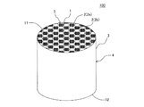
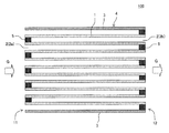
本発明の目封止ハニカム構造体の一の実施形態は、図1〜図5に示すような、柱状のハニカム構造部4と、セル2の開口部に配設された目封止部5と、を備えた目封止ハニカム構造体100である。ハニカム構造部4は、流体の流路となる第一端面11から第二端面12まで延びる複数のセル2を区画形成する多孔質の隔壁1を有する柱状のものである。目封止部5は、複数のセル2のいずれか一方の開口部に配設され、当該セル2の開口部を封止するものである。図1〜図5においては、目封止部5が、第一端面11における所定のセル2b(以下、単に「セル2b」ともいう)の開口部、及び第二端面12における残余のセル2a(以下、単に「セル2a」ともいう)の開口部に配設されている。このように構成された目封止ハニカム構造体100は、内燃機関、又は各種燃焼装置から排出される排ガスを浄化するパティキュレートフィルタとして用いることができる。図1〜図5に示す目封止ハニカム構造体100は、ハニカム構造部4の最外周に位置する外周壁3を更に有している。
One embodiment of the plugged honeycomb structure of the present invention includes a columnar honeycomb structure 4 as shown in FIGS. 1 to 5, and a plugged
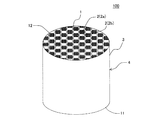
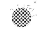
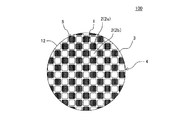
ここで、図1は、本発明の目封止ハニカム構造体の一の実施形態を流入端面側からみた模式的な斜視図である。図2は、図1に示す目封止ハニカム構造体を流出端面側からみた模式的な斜視図である。図3は、図1に示す目封止ハニカム構造体を流入端面側からみた模式的な平面図である。図4は、図1に示す目封止ハニカム構造体を流出端面側からみた模式的な平面図である。図5は、図1に示す目封止ハニカム構造体の、セルの延びる方向に平行な断面を示す模式的な断面図である。図5において、符号Gは、セル内を通過する流体(例えば、排ガス)を示し、符号Gに示す矢印の方向に流体が移動する。 Here, FIG. 1 is a schematic perspective view of one embodiment of the plugged honeycomb structure of the present invention as seen from the inflow end face side. FIG. 2 is a schematic perspective view of the plugged honeycomb structure shown in FIG. 1 as viewed from the outflow end face side. FIG. 3 is a schematic plan view of the plugged honeycomb structure shown in FIG. 1 as seen from the inflow end face side. FIG. 4 is a schematic plan view of the plugged honeycomb structure shown in FIG. 1 as viewed from the outflow end face side. FIG. 5 is a schematic cross-sectional view showing a cross section of the plugged honeycomb structure shown in FIG. 1 parallel to the cell extending direction. In FIG. 5, symbol G indicates a fluid (for example, exhaust gas) that passes through the cell, and the fluid moves in the direction of the arrow indicated by symbol G.
目封止ハニカム構造体100は、隔壁1が、主相としてα−Al2O3を含み、更にチタン酸アルミニウムとガラスを含む多孔体からなる。このような多孔体は、従来公知の目封止ハニカム構造体に用いられる隔壁の材料に比して、多孔体を構成する材料の単位体積当たりの熱容量が高いものである。目封止ハニカム構造体100においては、多孔体を構成する材料の単位体積当たりの熱容量が高いため、高温での使用に際して温度上昇を抑制することができ、耐熱衝撃性に優れるという顕著な効果を奏する。したがって、本実施形態の目封止ハニカム構造体100を、DPFとして用いた場合、当該DPFの再生時における温度上昇を抑制することができ、例えば、DPFの再生回数を減少させたとしても、熱衝撃による破損が生じ難くなる。
In the plugged
ここで、「材料の単位体積当たりの熱容量」とは、気孔等が形成されていない密実な材料において計測された熱容量のことを意味する。例えば、多孔体においては、当該多孔体に形成された気孔を考慮せず、多孔体を構成する材料自体の熱容量ということになる。以下、本明細書において、多孔体に形成された気孔を考慮した熱容量については、「多孔体の単位体積当たりの熱容量」と記し、上述した「材料の単位体積当たりの熱容量」とは区別するものとする。「材料の単位体積当たりの熱容量」を、単に「材料の熱容量」ということがある。「多孔体の単位体積当たりの熱容量」を、単に「多孔体の熱容量」ということがある。本明細書において、特に断りのない限り、「熱容量」とは、600℃における熱容量のことである。本明細書において、特に断りのない限り、「熱容量」及び「単位体積当たりの熱容量」の値は、1cm3当たりの熱容量(J/K/cm3)として示す。 Here, “the heat capacity per unit volume of the material” means the heat capacity measured in a solid material in which no pores or the like are formed. For example, in the case of a porous body, the heat capacity of the material itself constituting the porous body is considered without considering pores formed in the porous body. Hereinafter, in the present specification, the heat capacity in consideration of the pores formed in the porous body is referred to as “heat capacity per unit volume of the porous body” and is distinguished from the above-mentioned “heat capacity per unit volume of the material”. And The “heat capacity per unit volume of material” may be simply referred to as “heat capacity of material”. “The heat capacity per unit volume of the porous body” may be simply referred to as “the heat capacity of the porous body”. In this specification, unless otherwise specified, the “heat capacity” is a heat capacity at 600 ° C. In the present specification, unless otherwise specified, the values of “heat capacity” and “heat capacity per unit volume” are shown as heat capacity per 1 cm 3 (J / K / cm 3 ).
隔壁1を構成する多孔体における「主相」とは、質量割合において40質量%以上の物質をいう。一方、質量割合において20質量%未満の物質で、上述した主相に該当せず、且つX線回折法で同定された物質を、「副相」ということがある。本実施形態の目封止ハニカム構造体においては、多孔体に含まれるガラスなどが、副相に該当する。なお、多孔体における「主相」は、1種類に限られず、上記の条件を満たす物質が2種類存在する場合には、その2種類の物質が、共に「主相」となる。本明細書において、「物質」とは、化学的に見て一定の組成を持ち、物理的操作によって2種以上の物質に分離できないもの(物質)のことを意味する。
The “main phase” in the porous body constituting the
また、本明細書において、「チタン酸アルミニウム」を「Al2TiO5」と表記することがある。また、本明細書において、「Al2TiO5」や「α−Al2O3」と記載した場合は、その化学式にて記載された成分以外に、その他の成分が固溶している場合も含む。例えば、固溶しているその他の成分としては、Fe、Mg、Si等を挙げることができる。 Further, in this specification, “aluminum titanate” may be expressed as “Al 2 TiO 5 ”. In addition, in this specification, when “Al 2 TiO 5 ” or “α-Al 2 O 3 ” is described, in addition to the components described in the chemical formula, other components may be dissolved. Including. For example, Fe, Mg, Si, etc. can be mentioned as other components dissolved in solid.
多孔体のα−Al2O3とチタン酸アルミニウムとの質量比率(α−Al2O3/Al2TiO5)は、60/40〜90/10であり、70/30〜90/10であることが好ましく、80/20〜90/10であることが特に好ましい。例えば、多孔体に含まれるチタン酸アルミニウムの比率が相対的に多すぎる(別言すれば、α−Al2O3の比率が相対的に少なすぎる)と、多孔体を構成する材料の単位体積当たりの熱容量が十分に向上しないことがある。一方、多孔体に含まれるチタン酸アルミニウムの比率が相対的に少なすぎる(別言すれば、α−Al2O3の比率が相対的に多すぎる)と、多孔体の40〜800℃における平均熱膨張係数が大きくなってしまう。本実施形態の目封止ハニカム構造体においては、下記式(2)に示す「F」の値が、4.20以上であることが好ましく、熱容量が低い、又は平均熱膨張係数が大きくなると、この「F」の値が、4.20未満になってしまうことがある。 Porous body of α-Al 2 O 3 and the mass ratio of the aluminum titanate (α-Al 2 O 3 / Al 2 TiO 5) is Ri 60 / 40-90 / 10 Der, 70 / 30-90 / 10 it is good Mashiku is, particularly preferably 80 / 20-90 / 10. For example, when the proportion of aluminum titanate contained in the porous body is relatively too large (in other words, the proportion of α-Al 2 O 3 is relatively small), the unit volume of the material constituting the porous body The heat capacity per unit may not be improved sufficiently. On the other hand, if the proportion of aluminum titanate contained in the porous body is relatively small (in other words, the proportion of α-Al 2 O 3 is relatively large), the average of the porous body at 40 to 800 ° C. A thermal expansion coefficient will become large. In the plugged honeycomb structure of the present embodiment, the value of “F” shown in the following formula (2) is preferably 4.20 or more, and when the heat capacity is low or the average thermal expansion coefficient is large, The value of “F” may be less than 4.20.
F=C−0.007×α2 ・・・ (2)
(但し、上記式(2)において、Cは、多孔体を構成する材料の600℃における熱容量(J/K/cm3)を示し、αは、多孔体の40〜800℃における平均熱膨張係数(ppm/K)を示す。)
F = C−0.007 × α 2 (2)
(However, in said Formula (2), C shows the heat capacity (J / K / cm < 3 >) in 600 degreeC of the material which comprises a porous body, (alpha) is an average thermal expansion coefficient in 40-800 degreeC of a porous body. (Ppm / K).)
多孔体のα−Al2O3とチタン酸アルミニウムとの質量比率は、以下の方法により求めることができる。まず、目封止ハニカム構造体の隔壁を構成する多孔体を用いて、質量比率を求めるための試験片を作製する。試験片は、多孔体から、所定の大きさの試験片を切り出すことによって作製することができる。次に、得られた試験片を粉砕し、粉末状とする。試験片を粉末状にした後、その質量を測定しておく。得られた粉末を、ふっ酸を含む液体に投入する。ふっ酸を含む液体とは、ふっ酸(含有量46%)、硫酸(含有量97%)、塩酸(含有量36%)及び蒸留水を、10:2:3:25の容積比で混合したものである。ふっ酸を含む液体に粉末を投入した後、液体を0℃、30分間保持して、粉末中のガラスを溶解させる。その後、液体中の各溶質成分量を測定し、その各溶質成分を酸化物換算し、その総和をガラス量とする。例えば、Alは、Al2O3として酸化物換算する。このようにして、試験片に含まれるガラスの質量比率を求めることができる。その後、残渣中のα−Al2O3量を、X線回折(XRD)の内部標準法にて定量する。そして、残渣中の残りをAl2TiO5とする。このようにして測定されたα−Al2O3及びAl2TiO5の質量から、上記質量比率を求めることができる。ここで、「残渣」とは、粉末中のガラスを溶解させた後の粉末のことを意味する。また、「残渣中の残り」とは、残渣から、α−Al2O3量を差し引いたもののことを意味する。また、「X線回折(XRD)の内部標準法」とは、内部標準物質と試料を一定の割合で混合し、物質濃度と回折線強度比との間には直線関係が得られることを利用して、濃度が既知の標準試料で検量線を作成し分析する方法である。
The mass ratio of α-Al 2 O 3 and aluminum titanate in the porous body can be determined by the following method. First, a test piece for obtaining a mass ratio is prepared using a porous body constituting partition walls of a plugged honeycomb structure. The test piece can be produced by cutting out a test piece of a predetermined size from the porous body. Next, the obtained test piece is pulverized to form a powder. After making a test piece into powder form, the mass is measured. The obtained powder is put into a liquid containing hydrofluoric acid. The liquid containing hydrofluoric acid is a mixture of hydrofluoric acid (content 46%), sulfuric acid (content 97%), hydrochloric acid (
多孔体は、チタン酸アルミニウムにFe、Mg、及びSiからなる第一群より選択される少なくとも1種の成分が固溶したものであることが好ましい。多孔体に含まれるチタン酸アルミニウムに、上記第一群より選択される少なくとも1種の成分が固溶していると、多孔体によって構成される隔壁の耐熱分解性が向上する。 The porous body is preferably one in which at least one component selected from the first group consisting of Fe, Mg, and Si is dissolved in aluminum titanate. When at least one component selected from the first group is dissolved in the aluminum titanate contained in the porous body, the thermal decomposition resistance of the partition wall constituted by the porous body is improved.
チタン酸アルミニウムに固溶した成分については、以下の方法によって分析することができる。まず、目封止ハニカム構造体の隔壁を切断し、当該隔壁を構成する多孔体の切断面を樹脂に埋設する。その後、多孔体の切断面を研磨し、当該切断面を走査電子顕微鏡(以下、「SEM」ともいう)にて観察する。観察したSEM像(5000倍)において、Al2TiO5(チタン酸アルミニウム)、α−Al2O3、ガラスのそれぞれ部分の化学組成を、エネルギー分散型X線分析(以下、「EDS」ともいう)にて分析する。このような方法によって、チタン酸アルミニウム、α−Al2O3、ガラスのそれぞれ部分の化学組成を分析することができる。 Components dissolved in aluminum titanate can be analyzed by the following method. First, the partition walls of the plugged honeycomb structure are cut, and the cut surface of the porous body constituting the partition walls is embedded in the resin. Thereafter, the cut surface of the porous body is polished, and the cut surface is observed with a scanning electron microscope (hereinafter also referred to as “SEM”). In the observed SEM image (5000 times), the chemical composition of each part of Al 2 TiO 5 (aluminum titanate), α-Al 2 O 3 , and glass is also referred to as energy dispersive X-ray analysis (hereinafter also referred to as “EDS”). ) To analyze. By such a method, the chemical composition of each part of aluminum titanate, α-Al 2 O 3 , and glass can be analyzed.
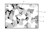
隔壁を構成する多孔体を観察したSEM像(SEM写真)は、例えば、図7に示すようなものである。図7は、本発明の目封止ハニカム構造体の一の実施形態における多孔体のSEM写真の一例を示す模式図である。SEM写真とは、走査電子顕微鏡によって撮像された写真のことである。図7に示すように、多孔体は、符号6に示される「α−Al2O3」と、符号7に示される「チタン酸アルミニウム」と、符号8に示される「ガラス」とを含むものである。そして、多孔体には、符号9に示される「気孔(細孔ともいう)」が複数形成されている。
An SEM image (SEM photograph) obtained by observing the porous body constituting the partition wall is, for example, as shown in FIG. FIG. 7 is a schematic view showing an example of an SEM photograph of a porous body in one embodiment of a plugged honeycomb structure of the present invention. An SEM photograph is a photograph taken with a scanning electron microscope. As shown in FIG. 7, the porous body includes “α-Al 2 O 3 ” indicated by
チタン酸アルミニウムに固溶した上記第一群に含まれる成分の固溶量が、0.1〜10.0質量%であることが好ましく、0.1〜5.0質量%であることが更に好ましく、0.5〜3.0質量%であることが特に好ましい。「第一群に含まれる成分の固溶量(質量%)」とは、以下の質量比率(質量%)のことを意味する。まず、固溶量にて示される質量比率(質量%)の分母は、チタン酸アルミニウムに含まれるAl及びTiを酸化物換算したAl2O3及びTiO2の質量と当該チタン酸アルミニウムに含まれる固溶成分を酸化物換算した質量の合計質量である。そして、「第一群に含まれる成分の固溶量(質量%)」とは、上記合計質量に対する、チタン酸アルミニウムに含まれる固溶成分のうちのFe、Mg、及びSiを酸化物換算したFe2O3、MgO、及びSiO2の各質量の比率(質量%)のことである。すなわち、本明細書において、「固溶量(質量%)」とは、固溶成分の酸化物置換における質量比率(質量%)のことを意味する。上記固溶成分とは、チタン酸アルミニウムに固溶した全ての成分のことであり、第一群に含まれる成分以外の成分も含む。上記第一群に含まれる成分の固溶量が、0.1質量%未満であると、この固溶した成分による好適な効果が十分に発揮されないことがある。上記第一群に含まれる成分の固溶量が、10.0質量%を超えると、平均熱膨張係数が大きくなることがある。上記第一群に含まれる成分の固溶量は、上述したチタン酸アルミニウムの化学組成を分析するEDSにおいて、チタン酸アルミニウムの部分を任意に各10点測定し、その成分比率について平均値を算出する。得られた成分比率から、上記固溶量を求めることができる。 The solid solution amount of the component contained in the first group dissolved in aluminum titanate is preferably 0.1 to 10.0% by mass, more preferably 0.1 to 5.0% by mass. It is preferably 0.5 to 3.0% by mass. The “solid solution amount (mass%) of components contained in the first group” means the following mass ratio (mass%). First, the denominator of the mass ratio (mass%) indicated by the solid solution amount is contained in the aluminum titanate and the masses of Al 2 O 3 and TiO 2 in terms of oxides of Al and Ti contained in the aluminum titanate. This is the total mass of the solid solution components in terms of oxides. And "the solid solution amount (mass%) of the component contained in the first group" is the oxide conversion of Fe, Mg, and Si in the solid solution component contained in the aluminum titanate with respect to the total mass. It is a ratio (mass%) of each mass of Fe 2 O 3 , MgO, and SiO 2 . That is, in this specification, the “solid solution amount (mass%)” means the mass ratio (mass%) in the oxide substitution of the solid solution component. The said solid solution component is all the components dissolved in aluminum titanate, and also includes components other than the components contained in the first group. When the solid solution amount of the component included in the first group is less than 0.1% by mass, a suitable effect by the solid solution component may not be sufficiently exhibited. When the solid solution amount of the component contained in the first group exceeds 10.0% by mass, the average thermal expansion coefficient may be increased. The amount of solid solution of the components included in the first group was determined by arbitrarily measuring 10 portions of the aluminum titanate portion in the EDS analyzing the chemical composition of the aluminum titanate described above, and calculating the average value for the component ratio. To do. The amount of the solid solution can be determined from the obtained component ratio.
隔壁を構成する多孔体は、α−Al2O3とチタン酸アルミニウムとガラスの合計100質量%に対して、ガラスを、5〜15質量%含むことが必要であり、5〜12質量%含むことが好ましく、7〜12質量%含むことが特に好ましい。α−Al2O3とチタン酸アルミニウムとガラスの合計100質量%に対して、ガラスの含有量が5質量%未満であると、隔壁(別言すれば、多孔体)の気孔率が高くなり、目封止ハニカム構造体の強度が低下することがある。α−Al2O3とチタン酸アルミニウムとガラスの合計100質量%に対して、ガラスの含有量が15質量%超であると、多孔体を構成する材料の単位体積当たりの熱容量が十分に向上しないことがある。多孔体中のガラスの含有量は、上述したα−Al2O3とチタン酸アルミニウムとの質量比率を求める際に、酸溶液に溶解したガラスの質量から求めることができる。なお、本明細書において、ガラスとはXRDにて特定の回折パターンを持たない酸化物のことをいう。 The porous body constituting the partition wall needs to contain 5 to 15% by mass of glass and 5 to 12% by mass with respect to 100% by mass of α-Al 2 O 3 , aluminum titanate and glass in total. it is good preferred, and particularly preferably contains 7-12 mass%. When the glass content is less than 5% by mass with respect to a total of 100% by mass of α-Al 2 O 3 , aluminum titanate and glass, the porosity of the partition walls (in other words, the porous body) becomes high. In addition, the strength of the plugged honeycomb structure may be reduced. The heat capacity per unit volume of the material constituting the porous body is sufficiently improved when the glass content exceeds 15% by mass with respect to 100% by mass in total of α-Al 2 O 3 , aluminum titanate and glass. There are things that do not. The content of the glass in the porous body can be determined from the mass of the glass dissolved in the acid solution when determining the mass ratio of α-Al 2 O 3 and aluminum titanate described above. Note that in this specification, glass refers to an oxide that does not have a specific diffraction pattern by XRD.
多孔体に含まれるガラスが、SiO2、及びAl2O3を含んでいてもよい。ガラスが、SiO2、及びAl2O3を含んでいると、多孔体によって構成される隔壁の強度が向上する。また、当該ガラスが、アルカリ金属、アルカリ土類金属、Ti、及びFeからなる群より選択される少なくとも1種の成分からなる酸化物を更に含んでいてもよい。上記群より選択される少なくとも1種を更に含んでいると、隔壁の強度がより向上する点で更に好ましい。ガラスに含まれる各成分については、チタン酸アルミニウムに固溶した成分を分析する方法と同様の方法によって分析することができる。すなわち、チタン酸アルミニウムに固溶した成分を分析する際のSEM像において、ガラス部分の化学組成を、EDSにて分析し、各成分を定性することができる。 The glass contained in the porous body may contain SiO 2 and Al 2 O 3 . Glass, as containing SiO 2, and Al 2 O 3, improves the strength of the partition constituted by the porous body. The glass may further include an oxide composed of at least one component selected from the group consisting of alkali metals, alkaline earth metals, Ti, and Fe. When at least one selected from the above group is further included, it is more preferable in that the strength of the partition wall is further improved. About each component contained in glass, it can analyze by the method similar to the method of analyzing the component dissolved in aluminum titanate. That is, in the SEM image when analyzing components dissolved in aluminum titanate, the chemical composition of the glass portion can be analyzed by EDS to qualify each component.
多孔体を構成する材料の真密度が、3.65〜3.85g/cm3であることが好ましく、3.70〜3.85g/cm3であることが更に好ましく、3.75〜3.85g/cm3であることが特に好ましい。多孔体を構成する材料の真密度が、上述数値範囲であると、多孔体中のガラスが少ないという点で好ましい。例えば、多孔体を構成する材料の真密度が、3.65g/cm3未満であると、熱容量が小さすぎることとなることがあり、3.85g/cm3超であると、低強度となり過ぎたり、平均熱膨張係数が大き過ぎたりすることがある。多孔体を構成する材料の真密度は、JIS R 1634に準拠して、アルキメデス法により測定することができる。 True density of the material constituting the porous body is preferably 3.65~3.85g / cm 3, more preferably from 3.70~3.85g / cm 3, 3.75~3. Particularly preferred is 85 g / cm 3 . It is preferable that the true density of the material constituting the porous body is in the above numerical range in that the glass in the porous body is small. For example, if the true density of the material constituting the porous body is less than 3.65 g / cm 3 , the heat capacity may be too small, and if it exceeds 3.85 g / cm 3 , the strength becomes too low. Or the average thermal expansion coefficient may be too large. The true density of the material constituting the porous body can be measured by the Archimedes method according to JIS R 1634.
多孔体を構成する材料の600℃における熱容量が、4.25〜4.50J/K/cm3であることが好ましく、4.30〜4.50J/K/cm3であることが更に好ましく、4.35〜4.50J/K/cm3であることが特に好ましい。多孔体を構成する材料の600℃における熱容量が、4.50J/K/cm3を超えると、平均熱膨張係数とのバランスが悪くなる点であまり好ましくない。一方、多孔体を構成する材料の600℃における熱容量が、4.25J/K/cm3未満であると、温度上昇の抑制効果が小さくなることがある。 Heat capacity at 600 ° C. of the material constituting the porous body is preferably from 4.25~4.50J / K / cm 3, more preferably from 4.30~4.50J / K / cm 3, It is particularly preferably 4.35 to 4.50 J / K / cm 3 . When the heat capacity at 600 ° C. of the material constituting the porous body exceeds 4.50 J / K / cm 3 , it is not preferable in that the balance with the average thermal expansion coefficient is deteriorated. On the other hand, if the heat capacity at 600 ° C. of the material constituting the porous body is less than 4.25 J / K / cm 3 , the effect of suppressing the temperature rise may be reduced.
多孔体を構成する材料の600℃における熱容量は、以下の方法によって求めることができる。まず、アルバック理工社製の断熱型比熱測定装置を用いて、多孔体を構成する材料の600℃における単位質量あたりの熱容量(J/K/g)を測定する。得られた単位質量あたりの熱容量(J/K/g)に、室温においてアルキメデス法で測定した多孔体を構成する材料の真密度(g/cm3)を乗算することで、多孔体を構成する材料の単位体積あたりの熱容量(J/K/cm3)を算出する。熱容量の測定は、隔壁を構成する多孔体から所定の大きさの試験片(サンプル)を切り出して作製し、当該試験片を用いて行うことができる。 The heat capacity at 600 ° C. of the material constituting the porous body can be determined by the following method. First, the heat capacity (J / K / g) per unit mass at 600 ° C. of the material constituting the porous body is measured using an adiabatic specific heat measuring device manufactured by ULVAC-RIKO. The obtained heat capacity (J / K / g) per unit mass is multiplied by the true density (g / cm 3 ) of the material constituting the porous body measured by the Archimedes method at room temperature to constitute the porous body. The heat capacity (J / K / cm 3 ) per unit volume of the material is calculated. The heat capacity can be measured by cutting out a test piece (sample) of a predetermined size from the porous body constituting the partition wall and using the test piece.
多孔体の40〜800℃における平均熱膨張係数が、2.5〜6.0ppm/Kであることが好ましく、3.0〜5.0ppm/Kであることが更に好ましく、4.0〜5.0ppm/Kであることが特に好ましい。多孔体の40〜800℃における平均熱膨張係数が、上記数値範囲であると、目封止ハニカム構造体の耐熱衝撃性が優れたものとなる。平均熱膨張係数が、2.5ppm/K未満であると、熱容量が小さくなり過ぎることがあるのであまり好ましくない。平均熱膨張係数が、6.0ppm/K超であると、耐熱衝撃性が低くなり過ぎることがあるのであまり好ましくない。平均熱膨張係数は、示差検出型の熱膨張計にて測定することができる。 The average thermal expansion coefficient at 40 to 800 ° C. of the porous body is preferably 2.5 to 6.0 ppm / K, more preferably 3.0 to 5.0 ppm / K, and 4.0 to 5 Particularly preferred is 0.0 ppm / K. When the average thermal expansion coefficient at 40 to 800 ° C. of the porous body is in the above numerical range, the thermal shock resistance of the plugged honeycomb structure is excellent. If the average thermal expansion coefficient is less than 2.5 ppm / K, the heat capacity may become too small, which is not preferable. If the average thermal expansion coefficient is more than 6.0 ppm / K, the thermal shock resistance may be too low, which is not preferable. The average coefficient of thermal expansion can be measured with a differential detection type thermal dilatometer.
多孔体が、下記式(3)の関係を満たすことが好ましい。
C−0.007×α2 ≧ 4.20 ・・・ (3)
(但し、上記式(3)において、Cは、多孔体を構成する材料の600℃における熱容量(J/K/cm3)を示し、αは、多孔体の40〜800℃における平均熱膨張係数(ppm/K)を示す。)
It is preferable that the porous body satisfies the relationship of the following formula (3).
C−0.007 × α 2 ≧ 4.20 (3)
(However, in said Formula (3), C shows the heat capacity (J / K / cm < 3 >) in 600 degreeC of the material which comprises a porous body, (alpha) is an average thermal expansion coefficient in 40-800 degreeC of a porous body. (Ppm / K).)
多孔体が、上記式(3)の関係を満たすと、本実施形態の目封止ハニカム構造体において、多孔体を構成する材料の600℃における熱容量(J/K/cm3)、及び多孔体の40〜800℃における平均熱膨張係数(ppm/K)の双方が好適な値となる。すなわち、熱容量(J/K/cm3)は、目封止ハニカム構造体の温度上昇の抑制に有効なパラメータであり、平均熱膨張係数(ppm/K)は、目封止ハニカム構造体の耐熱衝撃性の向上に有効なパラメータである。そして、多孔体が、上記式(3)の関係を満たす場合には、温度上昇の抑制効果と耐熱衝撃性の向上効果のバランスを図ることができる。 When the porous body satisfies the relationship of the above formula (3), in the plugged honeycomb structure of the present embodiment, the heat capacity (J / K / cm 3 ) of the material constituting the porous body at 600 ° C., and the porous body Both of the average thermal expansion coefficients (ppm / K) at 40 to 800 ° C. are suitable values. That is, the heat capacity (J / K / cm 3 ) is an effective parameter for suppressing the temperature rise of the plugged honeycomb structure, and the average thermal expansion coefficient (ppm / K) is the heat resistance of the plugged honeycomb structure. This is an effective parameter for improving impact properties. And when a porous body satisfy | fills the relationship of said Formula (3), the balance of the suppression effect of a temperature rise and the improvement effect of a thermal shock resistance can be aimed at.
多孔体の気孔率が、20〜50%であることが好ましく、20〜45%であることが更に好ましく、25〜45%であることが特に好ましい。多孔体の気孔率が、20%未満であると、目封止ハニカム構造体の圧力損失が増大することがある。多孔体の気孔率が、50%超であると、目封止ハニカム構造体の隔壁が脆くなり欠落し易くなることがある。また、多孔体の気孔率が高すぎると、多孔体の熱容量が小さくなるため、目封止ハニカム構造体が温度上昇しやすくなることがある。多孔体の気孔率とは、目封止ハニカム構造体の隔壁の気孔率のことである。多孔体の気孔率は、JIS R 1634に準拠して、アルキメデス法により測定することができる。 The porosity of the porous body is preferably 20 to 50%, more preferably 20 to 45%, and particularly preferably 25 to 45%. When the porosity of the porous body is less than 20%, the pressure loss of the plugged honeycomb structure may increase. When the porosity of the porous body is more than 50%, the partition walls of the plugged honeycomb structure may become brittle and easily missing. In addition, if the porosity of the porous body is too high, the heat capacity of the porous body becomes small, and the temperature of the plugged honeycomb structure may easily rise. The porosity of the porous body is the porosity of the partition walls of the plugged honeycomb structure. The porosity of the porous body can be measured by Archimedes method according to JIS R 1634.
多孔体の平均細孔径が、5〜20μmであることが好ましく、8〜15μmであることが更に好ましく、8〜12μmであることが特に好ましい。多孔体の平均細孔径が、5μm未満であると、目封止ハニカム構造体の圧力損失が大きくなることがある。多孔体の平均細孔径が、20μm超であると、目封止ハニカム構造体をDPF等のフィルタとして用いた際に、排ガス中のPMの一部が隔壁を通過することがあり、当該フィルタの捕集効率が低くなることがある。多孔体の平均細孔径は、JIS R 1655に準拠して、水銀圧入法により測定することができる。 The average pore diameter of the porous body is preferably 5 to 20 μm, more preferably 8 to 15 μm, and particularly preferably 8 to 12 μm. When the average pore diameter of the porous body is less than 5 μm, the pressure loss of the plugged honeycomb structure may increase. When the average pore diameter of the porous body is more than 20 μm, when the plugged honeycomb structure is used as a filter such as a DPF, a part of PM in the exhaust gas may pass through the partition wall, Collection efficiency may be low. The average pore diameter of the porous body can be measured by a mercury intrusion method according to JIS R 1655.
また、目封止ハニカム構造体のハニカム構造部が、隔壁を有する柱状のハニカムセグメントを、複数個有し、複数個のハニカムセグメントの互いの側面同士が対向するように隣接して配置された状態で接合されたセグメント構造であってもよい。セグメント構造のハニカム構造部を備えた目封止ハニカム構造体としては、例えば、図6に示すような目封止ハニカム構造体200を挙げることができる。図6に示す目封止ハニカム構造体200は、複数個のハニカムセグメント36が、互いの側面同士が対向するように隣接して配置された状態で、接合層37によって接合されたハニカム構造部34を備えたものである。ハニカムセグメント36は、第一端面41から第二端面42まで延びる流体の流路となる複数のセル32(セル32a,セル32b)を区画形成する多孔質の隔壁31及び隔壁31を取り囲むように配設された外壁38を有するものである。接合層37は、隣接して配置されるハニカムセグメント36の外壁38同士を接合するためのものである。この接合層37は、ハニカム構造部34に生じる熱応力を緩衝するための緩衝材としての機能を有していてもよい。図6に示す目封止ハニカム構造体200では、複数個のハニカムセグメント36が接合された接合体の最外周に、外周壁33が配置されている。
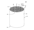
Further, the honeycomb structure part of the plugged honeycomb structure has a plurality of columnar honeycomb segments having partition walls, and is arranged adjacent to each other so that the side surfaces of the plurality of honeycomb segments face each other. It may be a segmented structure joined by An example of a plugged honeycomb structure provided with a segmented honeycomb structure is a plugged
セグメント構造のハニカム構造部においては、複数のハニカムセグメントのうち、少なくとも1つのハニカムセグメントの隔壁が、主相としてα−Al2O3を含み、更にチタン酸アルミニウムとガラスを含む多孔体からなることが好ましい。セグメント構造のハニカム構造部においては、全てのハニカムセグメントの隔壁が、主相としてα−Al2O3を含み、更にチタン酸アルミニウムとガラスを含む多孔体からなるものであってよい。接合層については、従来公知のセグメント構造のハニカム構造部における接合層と同様に構成されたものを用いることができる。 In the honeycomb structure portion of the segment structure, the partition walls of at least one honeycomb segment of the plurality of honeycomb segments include α-Al 2 O 3 as a main phase, and further include a porous body including aluminum titanate and glass. Is preferred. In the honeycomb structure portion having the segment structure, the partition walls of all the honeycomb segments may include a porous body containing α-Al 2 O 3 as a main phase and further containing aluminum titanate and glass. As the bonding layer, one that is configured in the same manner as the bonding layer in the honeycomb structure portion having a conventionally known segment structure can be used.
図6に示すような目封止ハニカム構造体200は、複数個のハニカムセグメント36を接合した接合体を得、得られた接合体の外周部を研削等によって加工したものであってもよい。接合体の外周部を加工することにより、当該接合体のセル32の延びる方向に直交する断面の形状を、円形等の所望の形状にすることができる。接合体の外周部を加工した後、最外周にセラミック材料を塗工することによって外周壁33を配置してもよい。図6は、本発明の目封止ハニカム構造体の他の実施形態を流入端面側からみた模式的な斜視図である。図6において、符号35は、セル32の開口部に配設された「目封止部」を示す。このような、所謂、セグメント構造の目封止ハニカム構造体であっても、図1〜図5に示すような、所謂、一体型の目封止ハニカム構造体と同様の作用効果を得ることができる。
A plugged
ハニカム構造部の隔壁の厚さについては特に制限はないが、100〜500μmであることが好ましく、150〜400μmであることが更に好ましく、150〜300μmであることが特に好ましい。隔壁の厚さをこのような範囲にすることにより、目封止ハニカム構造体の隔壁の強度を保ちつつ、圧力損失の上昇を抑制することができる。 Although there is no restriction | limiting in particular about the thickness of the partition of a honeycomb structure part, It is preferable that it is 100-500 micrometers, It is more preferable that it is 150-400 micrometers, It is especially preferable that it is 150-300 micrometers. By setting the thickness of the partition walls in such a range, an increase in pressure loss can be suppressed while maintaining the strength of the partition walls of the plugged honeycomb structure.
ハニカム構造部のセル密度については特に制限はないが、15〜100セル/cm2であることが好ましく、30〜65セル/cm2であることが更に好ましく、30〜50セル/cm2であることが特に好ましい。セル密度をこのような範囲にすることにより、目封止ハニカム構造体をDPF等に用いた場合には、圧力損失を抑制しつつ、捕集効率を向上させることができる。 There is no particular limitation on the cell density of the honeycomb structural portion, preferably from 15 to 100 cells / cm 2, further preferably 30 to 65 cells / cm 2, is 30 to 50 cells / cm 2 It is particularly preferred. By setting the cell density in such a range, when the plugged honeycomb structure is used for a DPF or the like, it is possible to improve the collection efficiency while suppressing the pressure loss.
ハニカム構造部に形成されるセルの形状については特に制限はない。ここで、「セルの形状」とは、ハニカム構造部のセルの延びる方向に直交する断面における、セルの形状のことである。セルの形状としては、例えば、四角形、六角形、八角形、又はこれらの組み合わせを挙げることができる。 There are no particular restrictions on the shape of the cells formed in the honeycomb structure. Here, the “cell shape” is a cell shape in a cross section orthogonal to the cell extending direction of the honeycomb structure portion. Examples of the shape of the cell include a quadrangle, a hexagon, an octagon, or a combination thereof.
ハニカム構造部の形状は、特に限定されず、例えば、底面が円形の柱状(円柱形状)、底面がオーバル形状の柱状、底面が多角形(四角形、五角形、六角形、七角形、八角形等)の柱状等の形状とすることができる。 The shape of the honeycomb structure is not particularly limited. For example, the bottom has a circular columnar shape (cylindrical shape), the bottom has an oval columnar shape, and the bottom has a polygonal shape (square, pentagon, hexagon, heptagon, octagon, etc.) The shape can be a columnar shape.
ハニカム構造部の第一端面から第二端面までの長さ、及びハニカム構造部のセルの延びる方向に直交する断面の大きさは、本実施形態の目封止ハニカム構造体を排ガス浄化のフィルタとして用いた際に、最適な浄化性能を得るように適宜選択すればよい。例えば、ハニカム構造部の第一端面から第二端面までの長さは、100〜500mmであることが好ましく、100〜300mmであることが更に好ましい。ハニカム構造部のセルの延びる方向に直交する断面の面積は、7000〜70000mm2であることが好ましく、7000〜30000mm2であることが更に好ましい。 The length from the first end surface to the second end surface of the honeycomb structure portion and the size of the cross section perpendicular to the cell extending direction of the honeycomb structure portion are determined using the plugged honeycomb structure of the present embodiment as a filter for exhaust gas purification. What is necessary is just to select suitably so that the optimal purification performance may be obtained when using. For example, the length from the first end surface to the second end surface of the honeycomb structure part is preferably 100 to 500 mm, and more preferably 100 to 300 mm. Area of the cross section perpendicular to the cell extension direction of the honeycomb structure is preferably 7000~70000Mm 2, and further preferably from 7000~30000mm 2.
ハニカム構造部の隔壁の表面及び隔壁の細孔のうちの少なくとも一方に、排ガス浄化用の触媒が担持されていてもよい。触媒としては、例えば、多孔質なγ−Al2O3に白金族金属を担持したものを挙げることができる。なお、ハニカム構造部の隔壁に担持された触媒は、隔壁(別言すれば、多孔体)とは異なる構成要素であるため、これまでに説明した「多孔体を構成する材料」には、当該触媒は含まないものとする。 An exhaust gas purifying catalyst may be supported on at least one of the surface of the partition walls of the honeycomb structure portion and the pores of the partition walls. Examples of the catalyst include a catalyst in which a platinum group metal is supported on porous γ-Al 2 O 3 . Note that the catalyst supported on the partition walls of the honeycomb structure portion is a different component from the partition walls (in other words, the porous body). Therefore, the “material constituting the porous body” described above includes The catalyst is not included.
次に、本実施形態の目封止ハニカム構造体の製造方法について説明する。目封止ハニカム構造体の製造する際には、まず、チタン酸アルミニウム、α−Al2O3、及びガラスを含む多孔体を作製するための成形原料を調製する。成形原料としては、成形原料を焼成することにより得られる焼成体(多孔体)中に、上記3物質が含まれ得るものであれば、特に制限はない。例えば、成形原料としては、所望量の、Al2O3、TiO2、タルク、マイカ、粘土等を配合して調製することができる。また、成形原料として、Al(OH)3、フォルステライト、長石、カオリン、Na2O、K2O、MgO、CaO、SrO、Fe2O3、Y2O3、La2O3、Ga2O3、ZrO2、CeO2、SiO2、CuO、NiO、これらの炭酸化物、水酸化物、塩化物、及び所望の組成に調整されたガラス等を用いることもできる。上述した原料の配合量を調節することにより、得られる多孔体に含まれる物質及びその比率を調整することができる。なお、成形原料の配合量については、得られる焼成体中において、少なくともα−Al2O3が主相(すなわち、質量割合において40質量%以上)となるように、その配合量を調節する。また、成形原料には、上述した原料に加えて、分散媒や添加剤を更に加えてもよい。 Next, a method for manufacturing the plugged honeycomb structure of the present embodiment will be described. When manufacturing a plugged honeycomb structure, first, a forming raw material for preparing a porous body containing aluminum titanate, α-Al 2 O 3 , and glass is prepared. The molding raw material is not particularly limited as long as the above three substances can be contained in a fired body (porous body) obtained by firing the molding raw material. For example, the molding raw material can be prepared by blending a desired amount of Al 2 O 3 , TiO 2 , talc, mica, clay, and the like. Moreover, as a forming raw material, Al (OH) 3 , forsterite, feldspar, kaolin, Na 2 O, K 2 O, MgO, CaO, SrO, Fe 2 O 3 , Y 2 O 3 , La 2 O 3 , Ga 2 O 3 , ZrO 2 , CeO 2 , SiO 2 , CuO, NiO, carbonates, hydroxides, chlorides thereof, and glass adjusted to a desired composition can also be used. By adjusting the blending amount of the raw materials described above, the substance contained in the obtained porous body and the ratio thereof can be adjusted. Note that the amount of the forming raw material, the sintered body to be obtained, at least α-Al 2 O 3 is the main phase (i.e., 40 wt% or more in mass ratio) and a way to adjust the amount thereof. Moreover, in addition to the raw material mentioned above, you may further add a dispersion medium and an additive to a shaping | molding raw material.
添加剤としては、バインダー、造孔材等を挙げることができる。分散媒としては、水等を挙げることができる。 Examples of the additive include a binder and a pore former. Examples of the dispersion medium include water.
バインダーとしては、メチルセルロース、ヒドロキシプロポキシルセルロース、ヒドロキシエチルセルロース、カルボキシメチルセルロース、ポリビニルアルコール等を挙げることができる。造孔材としては、焼成後に気孔となるものであれば特に限定されるものではなく、例えば、澱粉、発泡樹脂、吸水性樹脂、シリカゲル等を挙げることができる。 Examples of the binder include methyl cellulose, hydroxypropoxyl cellulose, hydroxyethyl cellulose, carboxymethyl cellulose, and polyvinyl alcohol. The pore former is not particularly limited as long as it becomes pores after firing, and examples thereof include starch, foamed resin, water absorbent resin, silica gel and the like.
上述した原料粉末の粒子径及び配合量、並びに添加する造孔材粉末の粒子径及び配合量を調整することにより、所望の気孔率、平均細孔径の多孔体を得ることができる。 By adjusting the particle diameter and blending amount of the raw material powder described above and the particle diameter and blending amount of the pore former powder to be added, a porous body having a desired porosity and average pore diameter can be obtained.
次に、得られた成形原料を混練して坏土を形成する。坏土を形成する方法としては、特に制限はなく、例えば、ニーダー、真空土練機等を用いる方法を挙げることができる。 Next, the obtained forming raw material is kneaded to form a clay. The method for forming the kneaded clay is not particularly limited, and examples thereof include a method using a kneader, a vacuum kneader or the like.
次に、得られた坏土を押出成形して、ハニカム成形体を作製する。押出成形は、所望のセル形状、隔壁厚さ、セル密度を有する口金を用いて行うことができる。次に、得られたハニカム成形体を乾燥させて、当該ハニカム成形体を乾燥させたハニカム乾燥体を得てもよい。乾燥方法は、特に限定されるものではないが、例えば、熱風乾燥、マイクロ波乾燥、誘電乾燥、減圧乾燥、真空乾燥、凍結乾燥等を挙げることができ、これらの中でも、誘電乾燥、マイクロ波乾燥又は熱風乾燥を単独で又は組合せて行うことが好ましい。また、乾燥条件としては、乾燥温度30〜150℃、乾燥時間1分〜2時間とすることが好ましい。 Next, the kneaded material obtained is extruded to produce a honeycomb formed body. Extrusion can be performed using a die having a desired cell shape, partition wall thickness, and cell density. Next, the obtained honeycomb formed body may be dried to obtain a dried honeycomb body obtained by drying the honeycomb formed body. The drying method is not particularly limited, and examples thereof include hot air drying, microwave drying, dielectric drying, reduced pressure drying, vacuum drying, freeze drying, etc. Among these, dielectric drying, microwave drying Or it is preferable to perform hot-air drying individually or in combination. The drying conditions are preferably a drying temperature of 30 to 150 ° C. and a drying time of 1 minute to 2 hours.
次に、得られたハニカム成形体又は当該ハニカム成形体を乾燥したハニカム乾燥体のセルの開口部を、目封止材によって目封止する。セルの開口部を目封止する方法としては、セルの開口部に目封止材を充填する方法を挙げることができる。目封止材を充填する方法としては、従来公知の目封止ハニカム構造体の製造方法に準じて行うことができる。目封止材を形成するためのセラミック原料は、従来公知の目封止ハニカム構造体の製造方法において用いられるセラミック原料を用いることができるが、ハニカム成形体(或いは、ハニカム乾燥体)と同じセラミック原料を用いることが好ましい。なお、目封止材によって形成される目封止部の気孔率や細孔径などを調節するために、セラミック原料粉末の粒子径及び配合量、並びに添加する造孔材粉末の粒子径及び配合量について適宜変更してもよい。 Next, the openings of the cells of the obtained honeycomb formed body or the dried honeycomb body obtained by drying the honeycomb formed body are plugged with a plugging material. Examples of the method of plugging the opening of the cell include a method of filling the opening of the cell with a plugging material. The plugging material can be filled in accordance with a conventionally known method for manufacturing a plugged honeycomb structure. As the ceramic raw material for forming the plugging material, a ceramic raw material used in a conventionally known method for manufacturing a plugged honeycomb structure can be used, but the same ceramic as the honeycomb formed body (or honeycomb dried body) is used. It is preferable to use raw materials. In order to adjust the porosity, pore size, etc. of the plugging portion formed by the plugging material, the particle size and blending amount of the ceramic raw material powder, and the particle size and blending amount of the pore former powder to be added You may change suitably about.
次に、目封止材をセルの開口部に充填したハニカム成形体(或いは、ハニカム乾燥体)を焼成する。得られたハニカム焼成体が、本実施形態の目封止ハニカム構造体となる。焼成温度は、1400〜1600℃が好ましく、1400〜1500℃が更に好ましい。また、焼成時間は、1〜10時間程度とすることが好ましい。焼成は、例えば、大気中、水蒸気雰囲気中、炭化水素ガス燃焼雰囲気中にて行うことができる。 Next, a honeycomb formed body (or a dried honeycomb body) in which the plugging material is filled in the opening of the cell is fired. The obtained honeycomb fired body becomes the plugged honeycomb structure of the present embodiment. The firing temperature is preferably 1400 to 1600 ° C, and more preferably 1400 to 1500 ° C. The firing time is preferably about 1 to 10 hours. Firing can be performed, for example, in the air, in a steam atmosphere, or in a hydrocarbon gas combustion atmosphere.
ハニカム成形体に目封止部を形成する前に、ハニカム成形体を焼成してハニカム焼成体を得、得られたハニカム焼成体のセルの開口部に目封止部を形成した後、更に焼成することによって目封止ハニカム構造体を得ることもできる。以上のようにして、本実施形態の目封止ハニカム構造体を製造することができる。 Before forming the plugged portions in the honeycomb formed body, the honeycomb formed body is fired to obtain a honeycomb fired body, and after the plugged portions are formed in the openings of the cells of the obtained honeycomb fired body, further firing is performed. By doing so, a plugged honeycomb structure can also be obtained. As described above, the plugged honeycomb structure of the present embodiment can be manufactured.
以下、本発明を実施例によって更に具体的に説明するが、本発明はこれらの実施例によって何ら限定されるものではない。 EXAMPLES Hereinafter, the present invention will be described more specifically with reference to examples, but the present invention is not limited to these examples.
以下に示す実施例においては、表1に示すような、α−Al2O3粉末、TiO2粉末、タルク粉末、マイカ粉末、及び粘土を原料とする原料粉末を用いて、成形原料を調製した。表1に、成形原料に用いられる原料粉末の種類、化学組成(質量%)、及び平均粒子径(μm)を示す。表1に示す原料粉末の化学組成は、蛍光X線分析法にて求めた。表1に示す原料粉末の平均粒子径は、レーザー回折法にて求めた。表1において、α−Al2O3の(1)〜(4)は、化学組成及び平均粒子径が異なるα−Al2O3原料粉末である。表1において、タルクの(1),(2)は、化学組成及び平均粒子径が異なるタルク原料粉末である。α−Al2O3の(1)に比して、α−Al2O3の(2)は、アルミナ(Al2O3)の純度が低い。α−Al2O3の(1)に比して、α−Al2O3の(3)は、平均粒子径が小さい。α−Al2O3の(1)に比して、α−Al2O3の(4)は、平均粒子径が大きい。タルクの(1)に比して、タルクの(2)は、酸化鉄(Fe2O3)が多く、且つ平均粒子径が大きい。
In the following examples, as shown in Table 1, a forming raw material was prepared using raw material powders using α-Al 2 O 3 powder, TiO 2 powder, talc powder, mica powder, and clay as raw materials. . Table 1 shows the type, chemical composition (mass%), and average particle diameter (μm) of the raw material powder used for the forming raw material. The chemical composition of the raw material powder shown in Table 1 was determined by fluorescent X-ray analysis. The average particle diameter of the raw material powder shown in Table 1 was determined by a laser diffraction method. In Table 1, the α-Al 2 O 3 (1 ) ~ (4) , the chemical composition and average particle size are different α-Al 2 O 3 raw material powder. In Table 1, talc (1) and (2) are talc raw material powders having different chemical compositions and average particle sizes. compared to (1) the α-Al 2 O 3, (2) α-Al 2 O 3, less

(実施例1)
実施例1においては、表1に示す、α−Al2O3の(1)、TiO2、タルクの(1)、及びマイカを用いて、成形原料を調製した。表2に、実施例1の成形原料の配合処方(単位:g)を示す。また、表2の「Al2O3/TiO2」の欄に、実施例1の成形原料に用いられるα−Al2O3の粉末に含まれる「Al2O3」と、TiO2の粉末に含まれる「TiO2」とのモル比(Al2O3/TiO2)を示す。
Example 1
In Example 1, a forming raw material was prepared using α-Al 2 O 3 (1), TiO 2 , talc (1), and mica shown in Table 1. Table 2 shows the compounding prescription (unit: g) of the molding raw material of Example 1. Furthermore, the
実施例1においては、表2の配合処方に示す原料の他に、造孔材として澱粉を50g、バインダーとしてメチルセルロースを200g、及び適量の水を添加した。 In Example 1, in addition to the raw materials shown in the formulation of Table 2, 50 g of starch as a pore former, 200 g of methylcellulose as a binder, and an appropriate amount of water were added.
次に、得られた成形原料をニーダーで混練し、次に、真空土練機で土練して、坏土を形成した。次に、得られた坏土を押出成形して、ハニカム成形体を作製した。ハニカム成形体は、焼成後において、隔壁の厚さが300μmとなり、セル密度が46.5セル/cm2となるものとした。ハニカム成形体のセルの形状は、焼成後において、正方形となるものとした。次に、ハニカム成形体を乾燥させて、ハニカム乾燥体を得た。乾燥は、まず、マイクロ波乾燥を行い、その後、熱風乾燥を行った。次に、得られたハニカム乾燥体のセルの開口部に目封止部を配設した。次に、得られたハニカム乾燥体を脱脂した。脱脂は、大気中、450℃で5時間行った。次に、脱脂したハニカム乾燥体を焼成して、目封止ハニカム構造体を得た。焼成は、大気中、1500℃で4時間行った。 Next, the obtained forming raw material was kneaded with a kneader, and then kneaded with a vacuum kneader to form a clay. Next, the obtained kneaded material was extruded to produce a honeycomb formed body. The honeycomb formed body had a partition wall thickness of 300 μm and a cell density of 46.5 cells / cm 2 after firing. The cell shape of the honeycomb formed body was assumed to be a square after firing. Next, the honeycomb formed body was dried to obtain a honeycomb dried body. For drying, first, microwave drying was performed, and then hot air drying was performed. Next, plugging portions were disposed in the opening portions of the cells of the obtained dried honeycomb body. Next, the obtained dried honeycomb body was degreased. Degreasing was performed in air at 450 ° C. for 5 hours. Next, the degreased honeycomb dried body was fired to obtain a plugged honeycomb structure. Firing was performed in the air at 1500 ° C. for 4 hours.
実施例1の目封止ハニカム構造体を構成する隔壁(多孔体)の組成を、以下の方法で定性、定量した。表3に、実施例1の目封止ハニカム構造体を構成する隔壁(多孔体)の組成を示す。なお、表3の「α−Al2O3/Al2TiO5」の欄は、α−Al2O3とAl2TiO5との質量比率(α−Al2O3/Al2TiO5)の値を示す。隔壁(多孔体)の組成の定性、定量に際し、まず、ガラスの量は、得られた目封止ハニカム構造体を構成する隔壁を、酸に浸漬し、当該隔壁中のガラスを溶解させ、ガラス量を定量した。その後、残渣中のα−Al2O3量をXRDにて定量し、残りをAl2TiO5とした。真密度(g/cm3)、及び気孔率(%)は、アルキメデス法(JIS R 1634)により測定した。平均細孔径(μm)は、水銀圧入法(JIS R 1655)により測定した。 The composition of the partition walls (porous body) constituting the plugged honeycomb structure of Example 1 was qualitatively and quantitatively determined by the following method. Table 3 shows the composition of the partition walls (porous body) constituting the plugged honeycomb structure of Example 1. In addition, the column of “α-Al 2 O 3 / Al 2 TiO 5 ” in Table 3 indicates the mass ratio of α-Al 2 O 3 and Al 2 TiO 5 (α-Al 2 O 3 / Al 2 TiO 5 ). Indicates the value of. In the qualitative and quantitative determination of the composition of the partition walls (porous body), first, the amount of glass was determined by immersing the partition walls constituting the obtained plugged honeycomb structure in an acid, and dissolving the glass in the partition walls. The amount was quantified. Thereafter, the amount of α-Al 2 O 3 in the residue was quantified by XRD, and the remainder was designated as Al 2 TiO 5 . The true density (g / cm 3 ) and the porosity (%) were measured by Archimedes method (JIS R 1634). The average pore diameter (μm) was measured by a mercury intrusion method (JIS R 1655).
熱容量(J/K/cm3)は、以下の方法で測定した。まず、アルバック理工社製の断熱型比熱測定装置を用いて、多孔体を構成する材料の600℃における単位質量あたりの熱容量(J/K/g)を測定した。次に、得られた単位質量あたりの熱容量(J/K/g)に、アルキメデス法で測定した室温における多孔体を構成する材料の真密度(g/cm3)を乗算することで、多孔体を構成する材料の単位体積あたりの熱容量(J/K/cm3)を算出した。 The heat capacity (J / K / cm 3 ) was measured by the following method. First, the heat capacity per unit mass at 600 ° C. (J / K / g) of the material constituting the porous body was measured using an adiabatic specific heat measuring device manufactured by ULVAC-RIKO. Next, by multiplying the obtained heat capacity per unit mass (J / K / g) by the true density (g / cm 3 ) of the material constituting the porous body at room temperature measured by the Archimedes method, The heat capacity per unit volume (J / K / cm 3 ) of the material that constitutes was calculated.
表3の「CTE(ppm/K)」は、平均熱膨張係数(ppm/K)のことである。多孔体の平均熱膨張係数は、示差検出型の熱膨張計にて、40〜800℃の平均熱膨張係数を測定することにより求めた。 “CTE (ppm / K)” in Table 3 is an average coefficient of thermal expansion (ppm / K). The average thermal expansion coefficient of the porous body was determined by measuring an average thermal expansion coefficient of 40 to 800 ° C. with a differential detection type thermal dilatometer.
表3の「F」は、「C−0.007×α2」の値を示す。ここで、Cは、多孔体を構成する材料の600℃における熱容量(J/K/cm3)を示し、αは、多孔体の40〜800℃における平均熱膨張係数(ppm/K)を示す。 “F” in Table 3 represents a value of “C−0.007 × α 2 ”. Here, C represents the heat capacity (J / K / cm 3 ) of the material constituting the porous body at 600 ° C., and α represents the average thermal expansion coefficient (ppm / K) of the porous body at 40 to 800 ° C. .
実施例1の目封止ハニカム構造体を構成する隔壁(多孔体)は、主相としてα−Al2O3を含み、更にAl2TiO5とガラスを含む多孔体からなるものであった。多孔体における、Al2TiO5の部分、α−Al2O3の部分、及びガラスの部分について、各部分の化学組成(質量%)を測定した。表4に、各実施例の目封止ハニカム構造体を構成する隔壁(多孔体)の「α−Al2O3」、「Al2TiO5」、及び「ガラス」の各部分の化学組成(質量%)の測定結果を示す。表4に示す化学組成は、以下の方法で分析した。まず、目封止ハニカム構造体の隔壁を切断し、当該隔壁を構成する多孔体の切断面を樹脂に埋設した。その後、多孔体の切断面を研磨し、当該切断面を走査電子顕微鏡(SEM)にて観察した。観察したSEM像(5000倍)において、α−Al2O3、Al2TiO5(チタン酸アルミニウム)、ガラスのそれぞれ部分の化学組成を、エネルギー分散型X線分析(EDS)にて分析した。
The partition walls (porous body) constituting the plugged honeycomb structure of Example 1 were composed of a porous body containing α-Al 2 O 3 as a main phase and further containing Al 2 TiO 5 and glass. In the porous body, the portion of the
(実施例2〜12及び参考例1〜3)
表2に示すような配合処方にて、実施例1と同様の方法で、目封止ハニカム構造体を作製した。実施例12においては、造孔材として添加する澱粉の量を500gとした。実施例2〜12及び参考例1〜3の目封止ハニカム構造体を構成する隔壁(多孔体)の組成を、実施例1と同様の方法で定性、定量した。表3に、実施例2〜12及び参考例1〜3の目封止ハニカム構造体を構成する隔壁(多孔体)の組成を示す。また、真密度(g/cm3)、気孔率(%)、平均細孔径(μm)、熱容量(J/K/cm3)、及びCTE(ppm/K)を、実施例1と同様の方法で測定した。測定結果を表3に示す。また、「C−0.007×α2」の値である「F」についても算出した。「F」の値を表3に示す。
(Examples 2 to 12 and Reference Examples 1 to 3 )
A plugged honeycomb structure was prepared in the same manner as in Example 1 with the formulation shown in Table 2. In Example 12 , the amount of starch added as a pore former was 500 g. The compositions of the partition walls (porous bodies) constituting the plugged honeycomb structures of Examples 2 to 12 and Reference Examples 1 to 3 were qualitatively and quantitatively determined in the same manner as in Example 1. Table 3 shows the composition of the partition walls (porous body) constituting the plugged honeycomb structures of Examples 2 to 12 and Reference Examples 1 to 3 . The true density (g / cm 3 ), porosity (%), average pore diameter (μm), heat capacity (J / K / cm 3 ), and CTE (ppm / K) were the same as in Example 1. Measured with Table 3 shows the measurement results. Further, “F” which is a value of “C−0.007 × α 2 ” was also calculated. The value of “F” is shown in Table 3.
実施例2〜12及び参考例1〜3の目封止ハニカム構造体を構成する隔壁(多孔体)は、主相としてα−Al2O3を含み、更にAl2TiO5とガラスを含む多孔体からなるものであった。多孔体における、α−Al2O3の部分、Al2TiO5の部分、及びガラスの部分について、各部分の化学組成(質量%)を測定した。表4に、実施例2,5,7,10,11の目封止ハニカム構造体を構成する隔壁(多孔体)の「α−Al2O3」、「Al2TiO5」、及び「ガラス」の各部分の化学組成(質量%)の測定結果を示す。
The partition walls (porous bodies) constituting the plugged honeycomb structures of Examples 2 to 12 and Reference Examples 1 to 3 include α-Al 2 O 3 as a main phase, and further include Al 2 TiO 5 and glass. It consisted of the body. In the porous body, portions of the α-Al 2 O 3, part of the
(比較例1)
表1のα−Al2O3の(1)、TiO2、タルク(1)、及びマイカを用いて、実施例1と同様の方法で、目封止ハニカム構造体を作製した。比較例1における成形原料の配合処方は、α−Al2O3の(1)を2550g、TiO2を1950g、タルクの(1)を350g、マイカを150gとした。造孔材、バインダー、及び水の添加量は、実施例1と同じにした。
(Comparative Example 1)
A plugged honeycomb structure was fabricated in the same manner as in Example 1 using α-Al 2 O 3 (1), TiO 2 , talc (1), and mica in Table 1. The blending formulation of the forming raw material in Comparative Example 1 was 2550 g of α-Al 2 O 3 (1), 1950 g of TiO 2 , 350 g of (1) of talc, and 150 g of mica. The amounts of pore former, binder and water added were the same as in Example 1.
(比較例2)
比較例2においては、平均粒子径12μmのα−SiC粉末と、平均粒子径2μmのα−SiC粉末とを用いて、成形原料を調製した。上記各粉末の使用量は、平均粒子径12μmのα−SiC粉末が3000g、平均粒子径2μmのα−SiC粉末の量が2000gである。また、成形原料には、バインダーとしてのメチルセルロースを300g、適量の水を添加した。比較例2においては、上記のように成形原料を調製し、且つ、ハニカム乾燥体の焼成を、アルゴン雰囲気中、2200℃で2時間としたこと以外は、実施例1と同様の方法で、目封止ハニカム構造体を作製した。
(Comparative Example 2)
In Comparative Example 2, a forming raw material was prepared using an α-SiC powder having an average particle size of 12 μm and an α-SiC powder having an average particle size of 2 μm. The amount of each powder used is 3000 g of α-SiC powder having an average particle size of 12 μm and 2000 g of α-SiC powder having an average particle size of 2 μm. In addition, 300 g of methyl cellulose as a binder and an appropriate amount of water were added to the forming raw material. In Comparative Example 2, the same procedure as in Example 1 was carried out except that the forming raw material was prepared as described above and the honeycomb dried body was fired at 2200 ° C. for 2 hours in an argon atmosphere. A sealed honeycomb structure was produced.
(比較例3)
比較例3においては、平均粒子径3μmのカオリン粉末と、平均粒子径24μmのタルク粉末と、平均粒子径6μmのアルミナ粉末と、平均粒子径21μmのシリカ粉末とを用いて、成形原料を調製した。上記各粉末の使用量は、カオリン粉末が1110g、タルク粉末が2135g、アルミナ粉末が1210g、シリカ粉末が540gである。造孔材、バインダー、及び水の添加量は、実施例1と同じにした。上記のように成形原料を調製し、且つ、ハニカム乾燥体の焼成を、1420℃で4時間としたこと以外は、実施例1と同様の方法で、目封止ハニカム構造体を作製した。
(Comparative Example 3)
In Comparative Example 3, a forming raw material was prepared using kaolin powder having an average particle size of 3 μm, talc powder having an average particle size of 24 μm, alumina powder having an average particle size of 6 μm, and silica powder having an average particle size of 21 μm. . The amount of each powder used is 1110 g for kaolin powder, 2135 g for talc powder, 1210 g for alumina powder, and 540 g for silica powder. The amounts of pore former, binder and water added were the same as in Example 1. A plugged honeycomb structure was produced in the same manner as in Example 1 except that the forming raw material was prepared as described above and the honeycomb dried body was fired at 1420 ° C. for 4 hours.
比較例1〜3の目封止ハニカム構造体を構成する隔壁(多孔体)について、実施例1と同様の方法で、真密度(g/cm3)、気孔率(%)、平均細孔径(μm)、熱容量(J/K/cm3)、及びCTE(ppm/K)を測定した。測定結果を表5に示す。また、「C−0.007×α2」の値である「F」についても算出した。「F」の値を表5に示す。 For the partition walls (porous bodies) constituting the plugged honeycomb structures of Comparative Examples 1 to 3, the true density (g / cm 3 ), porosity (%), average pore diameter ( μm), heat capacity (J / K / cm 3 ), and CTE (ppm / K) were measured. Table 5 shows the measurement results. Further, “F” which is a value of “C−0.007 × α 2 ” was also calculated. The value of “F” is shown in Table 5.
(結果)
実施例1の目封止ハニカム構造体は、比較例1〜3の目封止ハニカム構造体に比して、熱容量(J/K/cm3)が大きなものであった。α−Al2O3とAl2TiO5との質量比率を変えることにより、熱容量(J/K/cm3)が変化し、実施例2〜4の目封止ハニカム構造体は、実施例1の目封止ハニカム構造体よりも熱容量(J/K/cm3)が大きなものであった。参考例1は、α−Al2O3の質量比が60質量%を下回っていた。そのため、実施例1よりも熱容量が小さかった。参考例2は、α−Al2O3の質量比が90質量%を上回っていた。そのため、実施例4よりもCTEが大きかった。参考例3,実施例5の目封止ハニカム構造体においては、ガラスの質量比率が、実施例3の目封止ハニカム構造体に比して少なくなっていた。ガラスの質量比率が少なくなると、気孔率が大きくなる傾向が確認された。目封止ハニカム構造体の隔壁の気孔率が大きくなると、強度が低下することがある。実施例6の目封止ハニカム構造体においては、ガラスの質量比率が、実施例1の目封止ハニカム構造体に比して多くなっていた。実施例6の目封止ハニカム構造体は、実施例1の目封止ハニカム構造体よりも熱容量(J/K/cm3)が小さなものであった。
(result)
The plugged honeycomb structure of Example 1 had a larger heat capacity (J / K / cm 3 ) than the plugged honeycomb structures of Comparative Examples 1 to 3. By changing the mass ratio of α-Al 2 O 3 and Al 2 TiO 5 , the heat capacity (J / K / cm 3 ) was changed, and the plugged honeycomb structures of Examples 2 to 4 were obtained in Example 1. The heat capacity (J / K / cm 3 ) was larger than that of the plugged honeycomb structure. In Reference Example 1 , the mass ratio of α-Al 2 O 3 was less than 60% by mass. Therefore, the heat capacity was smaller than that of Example 1. In Reference Example 2 , the mass ratio of α-Al 2 O 3 exceeded 90 mass%. Therefore, CTE was larger than Example 4. In the plugged honeycomb structures of Reference Example 3 and Example 5 , the mass ratio of glass was smaller than that of the plugged honeycomb structure of Example 3. When the mass ratio of glass decreased, the tendency for the porosity to increase was confirmed. When the porosity of the partition walls of the plugged honeycomb structure increases, the strength may decrease. In the plugged honeycomb structure of Example 6 , the mass ratio of glass was larger than that of the plugged honeycomb structure of Example 1. The plugged honeycomb structure of Example 6 had a smaller heat capacity (J / K / cm 3 ) than the plugged honeycomb structure of Example 1.
実施例7の目封止ハニカム構造体は、成形原料に、比較的に純度の低いアルミナ(α−Al2O3の(2))を用いた。実施例7の目封止ハニカム構造体は、比較例1〜3の目封止ハニカム構造体に比して、熱容量(J/K/cm3)が大きなものであった。実施例8の目封止ハニカム構造体は、実施例1の目封止ハニカム構造体に比して、平均細孔径が小さなものであった。このような実施例8の目封止ハニカム構造体も、比較例1〜3の目封止ハニカム構造体に比して、熱容量(J/K/cm3)が大きなものであった。実施例9〜12においては、隔壁が、主相としてα−Al2O3を含み、更にチタン酸アルミニウムとガラスを含む多孔体となる範囲において、隔壁(多孔体)の組成を表3に示すように変化させた。このような実施例9〜12の目封止ハニカム構造体も、比較例1〜3の目封止ハニカム構造体に比して、熱容量(J/K/cm3)が大きなものであった。 In the plugged honeycomb structure of Example 7 , alumina having relatively low purity ((2) of α-Al 2 O 3 ) was used as a forming raw material. The plugged honeycomb structure of Example 7 had a larger heat capacity (J / K / cm 3 ) than the plugged honeycomb structures of Comparative Examples 1 to 3. The plugged honeycomb structure of Example 8 had a smaller average pore diameter than the plugged honeycomb structure of Example 1. Such a plugged honeycomb structure of Example 8 also had a larger heat capacity (J / K / cm 3 ) than the plugged honeycomb structures of Comparative Examples 1 to 3. In Examples 9 to 12 , the composition of the partition walls (porous body) is shown in Table 3 in a range in which the partition walls include α-Al 2 O 3 as a main phase and further become a porous body including aluminum titanate and glass. It was changed as follows. Such plugged honeycomb structures of Examples 9 to 12 also had larger heat capacities (J / K / cm 3 ) than the plugged honeycomb structures of Comparative Examples 1 to 3.
本発明の目封止ハニカム構造体は、排ガスを浄化する排ガス浄化用のフィルタとして利用することができる。 The plugged honeycomb structure of the present invention can be used as an exhaust gas purifying filter for purifying exhaust gas.
1,31:隔壁、2,32:セル、2a,32a:セル、2b,32b:セル、3,33:外周壁、4,34:ハニカム構造部、5,35:目封止部、6:α−Al2O3、7:チタン酸アルミニウム、8:ガラス、9:気孔、11,41:第一端面(端面)、12,42:第二端面(端面)、36:ハニカムセグメント、37:接合層、38:外壁(ハニカムセグメントの外壁)、100,200:目封止ハニカム構造体。 1, 31: partition wall, 2, 32: cell, 2a, 32a: cell, 2b, 32b: cell, 3, 33: outer peripheral wall, 4, 34: honeycomb structure portion, 5, 35: plugged portion, 6: α-Al 2 O 3 , 7: aluminum titanate, 8: glass, 9: pores, 11, 41: first end face (end face), 12, 42: second end face (end face), 36: honeycomb segment, 37: Bonding layer, 38: outer wall (outer wall of honeycomb segment), 100, 200: plugged honeycomb structure.
Claims (13)
前記第一端面における所定のセルの開口部、及び前記第二端面における残余のセルの開口部に配設された目封止部と、を備え、
前記隔壁が、主相として40質量%以上のα−Al2O3を含み、更にチタン酸アルミニウムとガラスを含む多孔体からなり、
前記多孔体の前記α−Al 2 O 3 と前記チタン酸アルミニウムとの質量比率が、60/40〜90/10であり、
前記多孔体が、前記α−Al 2 O 3 と前記チタン酸アルミニウムと前記ガラスの合計100質量%に対して、前記ガラスを5〜15質量%含む、目封止ハニカム構造体。 A columnar honeycomb structure having a porous partition wall that partitions a plurality of cells extending from a first end surface to a second end surface serving as a fluid flow path;
An opening of a predetermined cell on the first end surface, and a plugging portion disposed on an opening of a remaining cell on the second end surface,
The partition wall comprises 40 wt% or more of α-Al 2 O 3 as a main phase, Ri Do from the porous body further comprises aluminum titanate and glass,
The mass ratio of the α-Al 2 O 3 and the aluminum titanate of the porous body is 60/40 to 90/10,
A plugged honeycomb structure in which the porous body contains 5 to 15% by mass of the glass with respect to 100% by mass of the total of the α-Al 2 O 3 , the aluminum titanate, and the glass .
C−0.007×α2 ≧ 4.20 ・・・ (1)
(但し、上記式(1)において、Cは、前記多孔体を構成する材料の600℃における熱容量(J/K/cm3)を示し、αは、前記多孔体の40〜800℃における平均熱膨張係数(ppm/K)を示す。) The plugged honeycomb structure according to any one of claims 1 to 8 , wherein the porous body satisfies a relationship of the following formula (1).
C−0.007 × α 2 ≧ 4.20 (1)
(However, in said Formula (1), C shows the heat capacity (J / K / cm < 3 >) in 600 degreeC of the material which comprises the said porous body, (alpha) is an average heat in 40-800 degreeC of the said porous body. (Expansion coefficient (ppm / K) is shown.)
Priority Applications (3)
| Application Number | Priority Date | Filing Date | Title |
|---|---|---|---|
| JP2014052418A JP6231908B2 (en) | 2014-03-14 | 2014-03-14 | Plugged honeycomb structure |
| US14/621,586 US9506384B2 (en) | 2014-03-14 | 2015-02-13 | Plugged honeycomb structure |
| EP15157950.5A EP2918565B1 (en) | 2014-03-14 | 2015-03-06 | Plugged honeycomb structure |
Applications Claiming Priority (1)
| Application Number | Priority Date | Filing Date | Title |
|---|---|---|---|
| JP2014052418A JP6231908B2 (en) | 2014-03-14 | 2014-03-14 | Plugged honeycomb structure |
Publications (2)
| Publication Number | Publication Date |
|---|---|
| JP2015174036A JP2015174036A (en) | 2015-10-05 |
| JP6231908B2 true JP6231908B2 (en) | 2017-11-15 |
Family
ID=52874926
Family Applications (1)
| Application Number | Title | Priority Date | Filing Date |
|---|---|---|---|
| JP2014052418A Expired - Fee Related JP6231908B2 (en) | 2014-03-14 | 2014-03-14 | Plugged honeycomb structure |
Country Status (3)
| Country | Link |
|---|---|
| US (1) | US9506384B2 (en) |
| EP (1) | EP2918565B1 (en) |
| JP (1) | JP6231908B2 (en) |
Families Citing this family (8)
| Publication number | Priority date | Publication date | Assignee | Title |
|---|---|---|---|---|
| WO2017169363A1 (en) * | 2016-03-31 | 2017-10-05 | 日本碍子株式会社 | Monolithic base material and production method therefor |
| JP6756530B2 (en) * | 2016-07-05 | 2020-09-16 | イビデン株式会社 | Honeycomb structure and manufacturing method of honeycomb structure |
| EP3505244B1 (en) * | 2016-08-26 | 2021-09-22 | N.E. Chemcat Corporation | Honeycomb structure, honeycomb structure type catalyst, and production methods therefor |
| JP7049156B2 (en) * | 2018-03-30 | 2022-04-06 | 日本碍子株式会社 | Honeycomb filter |
| DE112019005966T5 (en) | 2018-11-30 | 2021-08-19 | Ngk Insulators, Ltd. | Honeycomb structure and exhaust gas purification device |
| CN113614292B (en) * | 2019-03-28 | 2024-08-23 | 日本碍子株式会社 | Semiconductor film |
| CN113336534B (en) * | 2021-06-28 | 2023-06-02 | 武汉理工大学 | A kind of low thermal expansion daily-use ceramics not containing lithium mineral and preparation method thereof |
| CN119140081B (en) * | 2024-11-14 | 2025-03-25 | 安徽中鼎美达环保科技有限公司 | Particle collector and preparation method thereof |
Family Cites Families (38)
| Publication number | Priority date | Publication date | Assignee | Title |
|---|---|---|---|---|
| US4483944A (en) * | 1983-07-27 | 1984-11-20 | Corning Glass Works | Aluminum titanate-mullite ceramic articles |
| CA1260909A (en) * | 1985-07-02 | 1989-09-26 | Koichi Saito | Exhaust gas cleaning catalyst and process for production thereof |
| US5198007A (en) * | 1991-12-05 | 1993-03-30 | The Dow Chemical Company | Filter including a porous discriminating layer on a fused single crystal acicular ceramic support, and method for making the same |
| US6300263B1 (en) * | 1999-12-16 | 2001-10-09 | Corning Incorporated | Low-expansion cordierite glass ceramics |
| EP1301261B1 (en) * | 2000-06-01 | 2011-07-13 | Corning Incorporated | Cordierite body |
| JP4284588B2 (en) * | 2003-01-10 | 2009-06-24 | トヨタ自動車株式会社 | Exhaust gas purification filter catalyst |
| ATE481151T1 (en) * | 2003-02-28 | 2010-10-15 | Ibiden Co Ltd | CERAMIC HONEYCOMB STRUCTURE |
| JP4945056B2 (en) * | 2003-09-12 | 2012-06-06 | オーセラ株式会社 | Honeycomb carrier for exhaust gas purification catalyst and manufacturing method thereof |
| WO2005105705A1 (en) * | 2004-04-30 | 2005-11-10 | Ngk Insulators, Ltd. | Honeycomb structure and method for producing same |
| EP1930058A3 (en) * | 2004-05-18 | 2008-07-30 | Ibiden Co., Ltd. | Honeycomb structural body and exhaust gas purifying device |
| US7071135B2 (en) * | 2004-09-29 | 2006-07-04 | Corning Incorporated | Ceramic body based on aluminum titanate and including a glass phase |
| JP5191657B2 (en) * | 2004-12-27 | 2013-05-08 | イビデン株式会社 | Ceramic honeycomb structure |
| EP1726698B1 (en) * | 2005-03-02 | 2013-07-10 | Ibiden Co., Ltd. | Inorganic fiber aggregate, method for producing inorganic fiber aggregate, honeycomb structure and method for producing honeycomb structure |
| JP4870559B2 (en) * | 2005-03-28 | 2012-02-08 | イビデン株式会社 | Honeycomb structure |
| US8119075B2 (en) * | 2005-11-10 | 2012-02-21 | Basf Corporation | Diesel particulate filters having ultra-thin catalyzed oxidation coatings |
| JPWO2007097056A1 (en) * | 2006-02-23 | 2009-07-09 | イビデン株式会社 | Honeycomb structure and exhaust gas purification device |
| WO2007102561A1 (en) * | 2006-03-07 | 2007-09-13 | Ngk Insulators, Ltd. | Ceramic structure and process for producing the same |
| KR101081638B1 (en) * | 2006-03-30 | 2011-11-09 | 엔지케이 인슐레이터 엘티디 | Bonded element, honeycomb segment bonded element, and honeycomb structure using the same |
| US7618699B2 (en) * | 2006-06-30 | 2009-11-17 | Corning Incorporated | Low-microcracked, porous ceramic honeycombs and methods of manufacturing same |
| US7927682B2 (en) * | 2006-06-30 | 2011-04-19 | Corning Incorporated | Low-microcracked, porous ceramic honeycombs and methods of manufacturing same |
| EP2069261A2 (en) | 2006-08-29 | 2009-06-17 | Corning Incorporated | Glass bonded ceramic structures |
| JP2008136981A (en) | 2006-12-05 | 2008-06-19 | Tokyo Yogyo Co Ltd | Honeycomb structure |
| US20080138569A1 (en) | 2006-12-11 | 2008-06-12 | Adam Kent Collier | Alpha-alumina inorganic membrane support and method of making the same |
| JPWO2008078799A1 (en) * | 2006-12-27 | 2010-04-30 | 日本碍子株式会社 | Honeycomb structure and manufacturing method thereof |
| KR20090125033A (en) | 2007-03-27 | 2009-12-03 | 니뽄 가이시 가부시키가이샤 | Sealed honeycomb structure |
| EP2158956B1 (en) * | 2007-04-27 | 2014-10-08 | NGK Insulators, Ltd. | Honeycomb filter |
| CN101861288B (en) * | 2007-11-14 | 2013-05-22 | 日立金属株式会社 | Aluminum titanate based ceramic honeycomb structure, process for production of the same and raw material powder for the production thereof |
| WO2009156652A1 (en) * | 2008-05-29 | 2009-12-30 | Saint-Gobain Centre De Recherches Et D'etudes Europeen | Cellular structure containing aluminium titanate |
| CN102046561A (en) * | 2008-05-30 | 2011-05-04 | 康宁股份有限公司 | Low back pressure porous honeycomb and method for producing the same |
| WO2010110011A1 (en) * | 2009-03-26 | 2010-09-30 | 日本碍子株式会社 | Honeycomb filter and method for producing honeycomb filter |
| WO2011061835A1 (en) * | 2009-11-19 | 2011-05-26 | イビデン株式会社 | Honeycomb structure and exhaust gas purification apparatus |
| WO2011061836A1 (en) * | 2009-11-19 | 2011-05-26 | イビデン株式会社 | Honeycomb structure and exhaust gas purification apparatus |
| EP2554236B1 (en) | 2010-03-31 | 2020-07-08 | NGK Insulators, Ltd. | Honeycomb filter |
| JP5597153B2 (en) * | 2011-03-24 | 2014-10-01 | 日本碍子株式会社 | Honeycomb filter and manufacturing method thereof |
| WO2012132004A1 (en) * | 2011-03-31 | 2012-10-04 | イビデン株式会社 | Honeycomb structure and exhaust gas cleaner |
| MX2015008461A (en) * | 2012-12-27 | 2015-09-23 | Sumitomo Chemical Co | Honeycomb filter and production method therefor, and aluminium titanate-based ceramic and production method therefor. |
| JP6231909B2 (en) * | 2014-03-14 | 2017-11-15 | 日本碍子株式会社 | Plugged honeycomb structure and manufacturing method thereof |
| US9487448B2 (en) * | 2014-03-18 | 2016-11-08 | Ngk Insulators, Ltd. | Honeycomb structure |
-
2014
- 2014-03-14 JP JP2014052418A patent/JP6231908B2/en not_active Expired - Fee Related
-
2015
- 2015-02-13 US US14/621,586 patent/US9506384B2/en active Active
- 2015-03-06 EP EP15157950.5A patent/EP2918565B1/en not_active Not-in-force
Also Published As
| Publication number | Publication date |
|---|---|
| US9506384B2 (en) | 2016-11-29 |
| US20150260065A1 (en) | 2015-09-17 |
| JP2015174036A (en) | 2015-10-05 |
| EP2918565A1 (en) | 2015-09-16 |
| EP2918565B1 (en) | 2018-07-18 |
Similar Documents
| Publication | Publication Date | Title |
|---|---|---|
| JP6231908B2 (en) | Plugged honeycomb structure | |
| JP6231909B2 (en) | Plugged honeycomb structure and manufacturing method thereof | |
| JP5981854B2 (en) | Honeycomb filter and manufacturing method thereof | |
| US11033885B2 (en) | Ceramic honeycomb structure and its production method | |
| JP6077484B2 (en) | Honeycomb structure | |
| US7473464B2 (en) | Porous material and method for production thereof | |
| JP6081951B2 (en) | Manufacturing method of honeycomb structure | |
| JPWO2009063997A1 (en) | Aluminum titanate ceramic honeycomb structure, method for producing the same, and raw material powder for producing the same | |
| JP2005530616A (en) | Aluminum magnesium silicate structure for DPF applications | |
| JP6231910B2 (en) | Plugged honeycomb structure | |
| CN114950029B (en) | Porous honeycomb structure and method for producing same | |
| JP4495152B2 (en) | Honeycomb structure and manufacturing method thereof | |
| JP2014108404A (en) | Honeycomb catalyst body | |
| CN104995154A (en) | Cordierite aluminum magnesium titanate compositions and ceramic articles comprising same | |
| JP6373782B2 (en) | Honeycomb structure | |
| JP4900820B2 (en) | Ceramic honeycomb filter | |
| JP5469335B2 (en) | Silicon carbide based porous material and method for producing the same | |
| JP6295111B2 (en) | Plugged honeycomb structure | |
| JP6231911B2 (en) | Plugged honeycomb structure | |
| JP2020049428A (en) | Honeycomb filter | |
| JP6483468B2 (en) | Honeycomb structure | |
| JP6257967B2 (en) | Porous material, honeycomb structure and honeycomb filter |
Legal Events
| Date | Code | Title | Description |
|---|---|---|---|
| A621 | Written request for application examination |
Free format text: JAPANESE INTERMEDIATE CODE: A621 Effective date: 20161017 |
|
| A977 | Report on retrieval |
Free format text: JAPANESE INTERMEDIATE CODE: A971007 Effective date: 20170412 |
|
| A131 | Notification of reasons for refusal |
Free format text: JAPANESE INTERMEDIATE CODE: A131 Effective date: 20170425 |
|
| A521 | Request for written amendment filed |
Free format text: JAPANESE INTERMEDIATE CODE: A523 Effective date: 20170626 |
|
| A131 | Notification of reasons for refusal |
Free format text: JAPANESE INTERMEDIATE CODE: A131 Effective date: 20170808 |
|
| A521 | Request for written amendment filed |
Free format text: JAPANESE INTERMEDIATE CODE: A523 Effective date: 20170928 |
|
| TRDD | Decision of grant or rejection written | ||
| A01 | Written decision to grant a patent or to grant a registration (utility model) |
Free format text: JAPANESE INTERMEDIATE CODE: A01 Effective date: 20171017 |
|
| A61 | First payment of annual fees (during grant procedure) |
Free format text: JAPANESE INTERMEDIATE CODE: A61 Effective date: 20171020 |
|
| R150 | Certificate of patent or registration of utility model |
Ref document number: 6231908 Country of ref document: JP Free format text: JAPANESE INTERMEDIATE CODE: R150 |
|
| LAPS | Cancellation because of no payment of annual fees |