EP1851005B1 - Coated abrasive articles - Google Patents
Coated abrasive articles Download PDFInfo
- Publication number
- EP1851005B1 EP1851005B1 EP06735533A EP06735533A EP1851005B1 EP 1851005 B1 EP1851005 B1 EP 1851005B1 EP 06735533 A EP06735533 A EP 06735533A EP 06735533 A EP06735533 A EP 06735533A EP 1851005 B1 EP1851005 B1 EP 1851005B1
- Authority
- EP
- European Patent Office
- Prior art keywords
- abrasive
- binder
- abrasive article
- article
- cartridge
- Prior art date
- Legal status (The legal status is an assumption and is not a legal conclusion. Google has not performed a legal analysis and makes no representation as to the accuracy of the status listed.)
- Not-in-force
Links
Images


Classifications
-
- B—PERFORMING OPERATIONS; TRANSPORTING
- B24—GRINDING; POLISHING
- B24D—TOOLS FOR GRINDING, BUFFING OR SHARPENING
- B24D5/00—Bonded abrasive wheels, or wheels with inserted abrasive blocks, designed for acting only by their periphery; Bushings or mountings therefor
-
- B—PERFORMING OPERATIONS; TRANSPORTING
- B24—GRINDING; POLISHING
- B24D—TOOLS FOR GRINDING, BUFFING OR SHARPENING
- B24D11/00—Constructional features of flexible abrasive materials; Special features in the manufacture of such materials
-
- B—PERFORMING OPERATIONS; TRANSPORTING
- B24—GRINDING; POLISHING
- B24D—TOOLS FOR GRINDING, BUFFING OR SHARPENING
- B24D18/00—Manufacture of grinding tools or other grinding devices, e.g. wheels, not otherwise provided for
-
- B—PERFORMING OPERATIONS; TRANSPORTING
- B24—GRINDING; POLISHING
- B24D—TOOLS FOR GRINDING, BUFFING OR SHARPENING
- B24D7/00—Bonded abrasive wheels, or wheels with inserted abrasive blocks, designed for acting otherwise than only by their periphery, e.g. by the front face; Bushings or mountings therefor
-
- B—PERFORMING OPERATIONS; TRANSPORTING
- B24—GRINDING; POLISHING
- B24D—TOOLS FOR GRINDING, BUFFING OR SHARPENING
- B24D2203/00—Tool surfaces formed with a pattern
-
- B—PERFORMING OPERATIONS; TRANSPORTING
- B33—ADDITIVE MANUFACTURING TECHNOLOGY
- B33Y—ADDITIVE MANUFACTURING, i.e. MANUFACTURING OF THREE-DIMENSIONAL [3-D] OBJECTS BY ADDITIVE DEPOSITION, ADDITIVE AGGLOMERATION OR ADDITIVE LAYERING, e.g. BY 3-D PRINTING, STEREOLITHOGRAPHY OR SELECTIVE LASER SINTERING
- B33Y30/00—Apparatus for additive manufacturing; Details thereof or accessories therefor
-
- B—PERFORMING OPERATIONS; TRANSPORTING
- B33—ADDITIVE MANUFACTURING TECHNOLOGY
- B33Y—ADDITIVE MANUFACTURING, i.e. MANUFACTURING OF THREE-DIMENSIONAL [3-D] OBJECTS BY ADDITIVE DEPOSITION, ADDITIVE AGGLOMERATION OR ADDITIVE LAYERING, e.g. BY 3-D PRINTING, STEREOLITHOGRAPHY OR SELECTIVE LASER SINTERING
- B33Y80/00—Products made by additive manufacturing
-
- Y—GENERAL TAGGING OF NEW TECHNOLOGICAL DEVELOPMENTS; GENERAL TAGGING OF CROSS-SECTIONAL TECHNOLOGIES SPANNING OVER SEVERAL SECTIONS OF THE IPC; TECHNICAL SUBJECTS COVERED BY FORMER USPC CROSS-REFERENCE ART COLLECTIONS [XRACs] AND DIGESTS
- Y10—TECHNICAL SUBJECTS COVERED BY FORMER USPC
- Y10T—TECHNICAL SUBJECTS COVERED BY FORMER US CLASSIFICATION
- Y10T442/00—Fabric [woven, knitted, or nonwoven textile or cloth, etc.]
- Y10T442/60—Nonwoven fabric [i.e., nonwoven strand or fiber material]
- Y10T442/608—Including strand or fiber material which is of specific structural definition
- Y10T442/609—Cross-sectional configuration of strand or fiber material is specified
- Y10T442/611—Cross-sectional configuration of strand or fiber material is other than circular
Definitions
- This disclosure in general, relates to rapid tooling systems and methods for manufacturing abrasive articles.
- Abrasive articles such as coated abrasives and bonded abrasives, are used in various industries to machine workpieces, such as by lapping, grinding, or polishing. Machining utilizing abrasive articles spans a wide industrial scope from optics industries, automotive paint repair industries, to metal fabrication industries. In each of these examples, manufacturing facilities use considerable quantities of abrasive articles during each business cycle.
- an abrasive article consumer orders a quantity of abrasive articles from an abrasive manufacturer.
- the abrasive manufacturer manufactures the abrasive article in a batch using a selected grain size and bonding material.
- the abrasive manufacturer may subsequently manufacture another batch of abrasive articles having a different grain size and bonding material.
- customers order in batches. For high volume users, ordering in batches results in large working capital outlay, storage and logistics problems once a batch is received, and problems associated with anticipating abrasive article usage. If usage of the abrasive articles is underestimated, the consumer may run out of abrasive articles, resulting in lost productivity and lost revenue.
- abrasive articles In addition, traditional methods for manufacturing abrasive articles produce excess waste and are limited in the shape and configuration of abrasive articles that may be formed through such methods. For example, when a particular contour of a coated abrasive is desired, a sheet of coated abrasive material is cut to match the contour, leaving a considerable amount of unused material as waste.
- traditional methods use a molding process that includes (i) preparing a batch of slurry, (ii) pouring the slurry into a mold, (iii) pressing and curing the slurry, (iv) de-molding, and (v) dressing to final size.
- excess factors are used throughout the manufacturing process. For example, excess slurry is made to ensure that the mold is fully filled.
- the mold is typically larger than the final size and the bonded abrasive article is trimmed to the final size in the dressing operation. As such, in both the coated abrasive and bonded abrasive manufacturing process, material is wasted and additional time consuming steps are performed to produce the final abrasive article.
- abrasive articles including bonded and coated abrasive articles.
- existing fabrication technology limits the architecture of abrasive articles, and in the context of engineered abrasives and bonded abrasives, typically abrasive structures are limited to structures that are easily detached from molding, such as conical or pyramidal shaped structures.
- US 2003/0150169 A1 relates to a coated abrasive article comprising a substrate and a patterned set of abrasive structures.
- Fig. 1 shows such coated abrasive article, wherein each abrasive structure of the patterned set of abrasive structures has an engineered microfeature, i.e. depressed areas and raised areas.
- EP 0 664 187 A1 relates to a grinding tape comprising a substrate and a patterned set of abrasive structures.
- Fig. 21 shows such grinding tape, wherein in each hexagonal island a recess of pin-hole shape is formed.
- a coated abrasive article comprises a substrate and a patterned set of abrasive structures.
- Each abrasive structure of the patterned set of abrasive structure has an engineered microfeature, which microfeature is a cleavage plane.
- the disclosure is to a system for manufacturing abrasive articles, such as a solid free form manufacturing system and a rapid tooling system.
- the system includes a computational circuitry, a cartridge and a production surface.
- the cartridge is removably coupled to the system, and abrasive particles and binder may be dispensed from the cartridge when the cartridge is engaged with the system.
- the computational circuitry is configured to control the deposition of or pattern in which the abrasive particles and binder are disposed on the production surface or substrate to form an abrasive article.
- the disclosure is directed to a cartridge that stores a binder and abrasive particles.
- the cartridge is configured to removably couple to a rapid tooling system for use in the manufacture of abrasive articles.
- the cartridge may further be configured to store a second binder and a second set of abrasive particles.
- the disclosure is also directed to a method of forming an abrasive article.
- the method includes providing an abrasive article design data set to a rapid tooling system and forming an abrasive article based on the abrasive article design data set.
- the method further includes providing a second abrasive article design data set and forming a second abrasive article based on the second abrasive article design data set.
- the disclosure is also directed to a method of facilitating abrasive article manufacturing.
- the method includes providing a rapid tooling system configured to accept a cartridge and providing the cartridge storing a binder and abrasive particles.
- the method may also include retrieving the used cartridge, refilling the cartridge with the binder and abrasive particles, and providing the refilled cartridge.
- the abrasive articles may be coated abrasive articles or bonded abrasive articles.
- Coated abrasive articles include articles in which a layer or layers of abrasive are bonded to a substrate.
- the substrate or backing member serves as a dimensionally stable component on which an abrasive containing layer is deposited. Abrasive grains of the abrasive layer adhere to the backing member through the use of binder.
- Engineered or structured abrasives have been developed to provide improved performance over traditionally coated abrasives. Structured abrasives use a backing member over which an abrasive layer is deposited in order to conform a pre-configured pattern. Such structured abrasives generally exhibit enhanced grinding characteristics over conventional abrasive products, such as providing sustained cut-rate, consistent surface finish and extended life.
- Bonded abrasives generally include three-dimensional forms that do not rely on a substrate or backing member for structural integrity. Bonded abrasives for example include grinding wheels and other three-dimensional abrasive articles. Traditionally, bonded abrasives have been formed through molding a mixture of abrasive particles and binder solutions.
- coated abrasives and bonded abrasives may be formed through rapid tooling methods and solid free form manufacturing methods.
- Rapid tooling methods for example, form an abrasive article, layer-by-layer, to produce an article having a desired grinding characteristic, such as sustained cut-rate, consistent surface finishing, useful life, porosity, and cutting fluid/swarf channeling.
- Rapid tooling methods include immersion methods and printing methods.
- Immersion methods generally include a bath or container filled with build material, such as a resin or powder.
- build material such as a resin or powder.
- An object is built, layer-by-layer, upon a platform that is lowered after each build layer is formed.
- a thin layer of uncured or unbound build material is deposited just above the last layer of the abrasive article and partially bound in a pattern.
- an energy source such as a laser or UV light source, is directed in a pattern at the layer of unbound material to cause binder within the material to sinter or cure.
- binder is printed in a pattern over the layers of build material. The object is then lowered, a subsequent layer of unbound material is deposited over the previous layer, and the unbound material is again solidified in a pattern to form an abrasive article.
- Exemplary immersion methods include liquid methods and powder methods.
- liquid methods include stereolithography in which an object is constructed in a pool of liquid resin.
- Powder methods include binder printing and selective laser sintering.
- a layer of ceramic material may be bound in a particular pattern by printing binder over the layer in the particular pattern.
- powder material may be sintered in a particular pattern by directing a laser beam over a layer of powder material in the particular pattern.
- Rapid printing methods generally include the deposition of solutions in a pattern over a substrate.
- an abrasive article is formed by the successive deposition of a solution including abrasive particles and binders.
- Exemplary printing methods include deposition printing methods and extrusion methods.
- Exemplary deposition methods include dry particle deposition methods, such as metal bonded systems, and liquid deposition methods, such as liquid curable resin systems.
- Extrusion methods include fused deposition machining (FDM) in which a filament of thermoplastic material is melted and deposited in a desired pattern.
- FDM fused deposition machining
- FIGS. 1 and 2 illustrate exemplary immersion systems for the formation of abrasive articles.
- the system 100 illustrated in FIG. 1 includes a bath 102 of uncured solution 104 including uncured resin and abrasive particles.
- An abrasive article 108 is formed on a platform 106.
- Energy source 112 such as a laser or ultraviolet (UV) energy source, directs energy in a pattern along a surface layer of the solution 104 to cure or bind the solution into a patterned layer.
- a laser may be scanned across the surface layer to form the pattern on the surface of the solution 104.
- UV light is directed through a mask to form the pattern on the surface of the solution 104.
- the platform 106 is subsequently lowered fractionally and a bar or sweeper 110 sweeps a subsequent layer of uncured solution over the forming abrasive article 108.
- the process continues by directing a subsequent pattern of energy at the surface layer, lowering the platform 106 and sweeping an additional layer over a previously cured layer.
- platform 106 is raised and the abrasive article 108 cleaned and rinsed with solvent.
- the object may be further post-cured using thermal or UV methods.
- the solution 104 includes abrasive particles and binder or curable resin.
- the binder or curable resin is responsive to at least one of heat, laser irradiation, UV energy irradiation, e-beam irradiation or patterned light methods. By directing the energy or light in a pattern, a layer of an abrasive article can be formed.
- the system illustrated in FIG. 1 includes a stereolithography system.
- FIG. 2 illustrates an exemplary system 200 using a powder mixture.
- a container 202 includes a mixture 204 of abrasive particles and powder binder.
- the mixture 204 may include binders, such as ceramic powders, polymeric materials, such as polyamides and polystyrenes, steel and foundry sand.
- a platform 206 is lowered to permit formation of abrasive article 208 layer-by-layer. Once the platform has been lowered by fractions of an inch, a roller 210 deposits build material over the abrasive article 208 and the material 204 within the container 202. Excess material may be wiped or rolled into container 214.
- An energy source 212 directs patterned energy on the surface of the material 204 to form a subsequent layer of abrasive article 208.
- the energy source 212 is a laser light source directed in a pattern over material 204 and abrasive article 208.
- the material 204 is abrasive particles. Binder or adhesive is printed in a pattern over the forming abrasive article 208 and material 204 to form a layer of the forming abrasive article.
- the platform 206 is lowered to allow the formation of a subsequent patterned layer.
- the platform 206 is raised and the abrasive article 208 cleaned of unbound powder.
- Exemplary embodiments of the system illustrated in FIG. 2 include binder printing systems and selective laser sintering systems (SLS).
- FIGS. 3, 4 and 5 illustrate exemplary printing systems.
- FIG. 3 illustrates a system 300 in which a filament of a thermoplastic material 308 is fed through a heated extrusion head 310.
- a platform 302 and/or the heated extrusion head 310 may move in a three-dimensional pattern to facilitate the formation of a three-dimensional abrasive article 304.
- a spool 306 includes the filament 308, which includes abrasive particles and the thermoplastic material that when heated temporarily melts and is deposited to form layers of the abrasive article 304.
- Exemplary thermoplastic materials include acrylonitrile-butadiene-styrene (ABS), polycarbonate, and polyphenylsulphone.
- the system 300 illustrated in FIG. 3 is a fused deposition machining (FDM) system.
- FDM fused deposition machining
- FIG. 4 illustrates an exemplary deposition printing system 400 in which powder is fused at locations on an abrasive article 404.
- a platform 402 and/or a deposition head 406 are moved in a three-dimensional pattern to facilitate the formation, layer-by-layer, of abrasive article 404.
- a laser, high-intensity light source, or radiative heat source is directed through the deposition head 406 and powder is directed through tube 408 to converge on the surface of abrasive article 404.
- the powder is sintered, melted, or cured in a pattern to form the abrasive article 404.
- the powder may be deposited as a single stream of powder including abrasive particles and binder or as two or more converging streams, one including abrasive particles and another including binder.
- exemplary binders include metals, such as steel, copper, titanium, or aluminum.
- the process includes depositing a stream of powdered metal and abrasives while simultaneously heating the deposition area with a laser to fuse the powder to the abrasive article 404.
- FIG. 5 illustrates another exemplary deposition printing system 500 that includes printing of successive layers to form an abrasive article 504.
- a platform 502 and/or a print head 506 are moved in a three-dimensional pattern to facilitate deposition of a resin-based solution in a patterned layer to form the abrasive article 504.
- the resin-based solution is subsequently cured to facilitate the formation of the abrasive article 504.
- the printing method includes a resin-based deposition method that prints a UV curable acrylide solution including abrasive particles in a patterned build layer.
- the build layer is exposed to UV light from an energy source, such as a radiation source 508.
- the print head 506 deposits one or more solutions in patterns in order to facilitate formation of abrasive articles having desired shapes and microfeatures, such as locally controlled porosity, engineered cleavage planes, and swarf channels.
- the systems described above in relation to FIGs 1-5 and, in particular, the rapid tooling printing systems may be adapted to receive a cartridge.
- the cartridge may be removably coupled to the system and house binder and abrasive particles.
- the cartridge includes a container for storing a solution or mixture of abrasive particles and binder.
- the solution may be a slurry of liquid binder and abrasive particles.
- the solution is a powdered mixture of abrasive particles and powder binder.
- the cartridge includes a spool for storing a filament composition including thermoplastic binder and abrasive particles.
- FIG. 6 illustrates one particular embodiment 600 of a rapid structuring media cartridge for use in a printing-type rapid tooling system.
- the cartridge is operable to successively deposit binder and/or abrasive grains in successive layers to form an abrasive structure, such as a coated abrasive structure or a bonded abrasive structure.
- the cartridge 600 may removably couple to a deposition printing rapid tooling system.
- the cartridge 600 includes a container 602 and a dispensing nozzle 604.
- the cartridge 600 may also include a refill port 606 and may include a unique identifier 608.
- the cartridge 600 is configured to store a binder and abrasive particles.
- the binder and abrasive particles may be combined together in a common compartment, such as container 602, in the cartridge body.
- the binder and abrasive particles are dispensed from a common nozzle, such as nozzle 604. If the binder is liquid, the abrasive particles and binder form a solution, such as a slurry of liquid binder and solid abrasive particles. If the binder is particulate, the abrasive particles and binder form a particulate mixture.
- the binder is radiatively curable.
- the binder may be curable through exposure to an e-beam, to a laser source or to diffuse light, such as UV light.
- a solution of the binder and abrasive particles further includes a second binder that is curable using alternative methods, such as thermal curing and chemically induced curing.
- the dispensing nozzle or orifice 604 is selectively controlled to dispense material.
- the dispensing nozzle 604 may form a portion of a print head.
- the nozzle 604 includes mechanisms for controlling the dispensing of a solution. Exemplary mechanisms include heater-driven bubble jet mechanisms, electrostatic mechanisms, and piezoelectric mechanisms.
- the orifice 604 provides material to a print head that is separate from the cartridge.
- FIG. 7 illustrates an exemplary cartridge 700 that includes two or more containers, 702 and 704.
- the cartridge 700 also includes one or more dispensing nozzles (706 and 712) and one or more refill ports (708 and 710).
- the binder and abrasive particles are separated from each other in dedicated compartments, such as containers 702 and 704.
- the compartments may be configured to dispense the binder and abrasive particles through a common nozzle, such as nozzle 706.
- the cartridge 700 may include dispensing structures configured to combine the first binder and first abrasive particles prior to dispensing such that the first binder and the first abrasive particles are dispensed through one nozzle.
- the compartments may be configured to dispense the binder and abrasive particles through separate nozzles, such as nozzles 706 and 712.
- a container such as container 702 includes a solution having a first set of abrasive particles and a first uncured binder.
- a second solution stored in container 704 includes a second uncured binder and, optionally, includes a second set of abrasive particles.
- the second binder exhibits post-cure mechanical properties, such as post-cure mechanical strength, that are different from the post-cure mechanical properties of the first binder.
- the second set of abrasive particles may have a different composition, average grain size, morphology, performance and/or hardness than the first abrasive particles.
- abrasive articles produced with the first solution have different performance characteristics, such as wear resistance and material removal rate, than abrasive articles produced with the second solution. Additionally, regions within an article produced with different ratios of the first and second solution have different performance characteristics.
- the abrasive article is a coated abrasive article.
- the cartridge may deposit the first binder to form a make coat and a second binder to form a size coat.
- the cartridge may also include a third binder in a third container.
- the third binder may, for example, be deposited to form a supersize coat of the coated abrasive article.
- the second solution stored in container 704 includes a curing agent.
- the curing agent may induce the first binder to polymerize, crosslink or solidify.
- the second solution may act as a diluent, reducing the density of abrasive particle placement or altering the mechanical strength of the first binder.
- the second solution stored in container 704 includes an adhesive for forming a pressure-sensitive adhesive backing to an abrasive article.
- the second solution may be deposited on a release film to form the pressure-sensitive adhesive backing.
- the binder and abrasive particles may be deposited over the adhesive backing to form the abrasive article.
- the abrasive article may be removed from the release film and pressed to surfaces of grinding, polishing, or fining equipment.
- the one or more refill ports (708 and 710) may be used by a consumer, a service provider or a manufacturer to refill the cartridge 700.
- the consumer may specify to the service provider or manufacturer the binder and abrasive particles with which the cartridge should be filled.
- the consumer may enter the unique identifier 714 into a website and specify the desired binder and abrasive particles with which the cartridge 700 associated with the unique identifier 714 should be filled. The consumer may then send the cartridge 700 to the service provider or manufacturer.
- the cartridge is configured for use in a 3-D deposition printing apparatus.
- the cartridge is configured for use in a FDM system, selective laser sintering system, or metal deposition system.
- the containers are spools for storing thermoplastic filaments or are configured to store powdered mixtures.
- cartridges are selectively coupled to the rapid tooling system or solid free form manufacturing system.
- a cartridge storing one composition can be replaced with a cartridge storing a different composition to produce abrasive articles with different characteristics.
- the solutions, mixed powders and filaments may be formed with a binder and set of abrasive particles.
- the binders may take the form of curable resins, such as resins curable via energetic methods, such as e-beam, microwave, laser, and UV curing methods.
- the binders are curable via chemical methods, such as catalyst induced or moisture induced methods, or via thermal methods.
- a particularly useful UV-curable binder composition contains constituents chosen from the group of acrylate and methacrylate oligomers and monomers.
- Useful oligomers include epoxy acrylates, aliphatic urethane acrylates, aromatic urethane acrylates, polyester acrylates, aromatic acid acrylates, epoxy methacrylates, and aromatic acid methacrylates.
- Monomers include mono-, di-, tri-, tetra-, and pentafunctional acrylates and methacrylates, such as trimethylopropane triacrylate, trimethylolpropane triacrylate, tris (2-hydroxy ethyl) isocyanuarate triacrylate, tripropylene glycol diacrylate, hexanediol diacrylate, octyl acrylate, octyl acrylate, and decyl acrylate.
- the binder formulation may include substantial amounts of acrylate monomers containing 3 or more acrylate groups per molecule.
- commercial products include, trimethylopropane triacrylate (TMPTA) and pentaerythritol triacrylate (PETA).
- TMPTA trimethylopropane triacrylate
- PETA pentaerythritol triacrylate
- the relative amounts of di- and tri-functional acrylates as well as higher molecular weight acrylate oligomers
- the radiant power of the source of actinic light can be provided by any conventional UV source.
- the coatings or build layers may be exposed to UV light generated from V, D, H, or H+ bulbs, or a combination thereof at an energy output ranging from 100 watts per inch of width to 600 watts per inch of width.
- coupling agents may be utilized to improve the bonding between the binder and the abrasive grains.
- Typical coupling agents include organosilanes, for example A-174 and A-1100 available from Osi Specialties, Inc., and organotitanates and zircoaluminates.
- a particular group of coupling agents includes amino silanes and methacryloxy silanes.
- Fillers can be incorporated into the dispersion to modify the rheology of the dispersion and the hardness and toughness of the cured binders.
- useful fillers include: metal carbonates, such as calcium carbonate, sodium carbonate; silicas such as quartz, glass beads, glass bubbles; silicates such as talc, clays, calcium metasilicate; metal sulfate such as barium sulfate, calcium sulfate, aluminum sulfate; metal oxides such as calcium oxide, aluminum oxide (such as in the form of boehmite and/or pseudo-boehmite); and aluminum trihydrate.
- metal carbonates such as calcium carbonate, sodium carbonate
- silicas such as quartz, glass beads, glass bubbles
- silicates such as talc, clays, calcium metasilicate
- metal sulfate such as barium sulfate, calcium sulfate, aluminum sulfate
- metal oxides such as calcium oxide, aluminum oxide (such as
- the dispersion may comprise a grinding aid to increase the grinding efficiency and cut rate.
- Useful grinding aids can be inorganic based, such as halide salts, for example sodium cryolite, potassium tetrafluoroborate, etc.; or organic based, such as chlorinated waxes, for example polyvinyl chloride.
- a particular embodiment includes cryolite and potassium tetrafluoroborate with particle size ranging from 1 to 80 micron, and most preferably from 5 to 30 micron.
- the weight percent of grinding aid ranges from 0 to 50%, and most preferably from 10-30% of the entire formulation (including the abrasive components).
- a photoinitiator such as a benzoin ether, benzil ketal, ⁇ -alkoxy-acetophenone, ⁇ -hydroxy-alkylphenone, ⁇ -amino alkylphenone, acyl phosphine oxide, benzophenone/amine, thioxanthone/amine, or another free radical generator; anti-static agents, such as graphite, carbon black, and the like; suspending agents, such as fumed silica; anti-loading agents, such as zinc stearate; lubricants, such as wax; wetting agents; dyes; fillers; viscosity modifiers; dispersants; and defoamers.
- a photoinitiator such as a benzoin ether, benzil ketal, ⁇ -alkoxy-acetophenone, ⁇ -hydroxy-alkylphenone, ⁇ -amino alkylphenone, acyl phosphine oxide, benzophenone/amine, thio
- thermoset polymers In alternative rapid tooling systems or in combination with the above-described binders, various thermal curable polymers may be utilized. While thermoplastic and thermoset polymers may be utilized, oftentimes thermoset polymers are emphasized due to their stable nature, particularly in the context of cutting or finishing operations that generate excessive heat.
- the binder compound includes a powder, typically formed principally of powder or even essentially entirely powder.
- liquid thermally curable polymers are used.
- liquid thermally curable polymers are excluded in favor of powder. Powder form thermal curable binders are particularly advantageous in some embodiments, as such may be incorporated into a process for forming coated abrasives fairly easily.
- thermal curable binder is particularly advantageous for creation of abrasive dispersions used for forming structured abrasives.
- thermal curable components in powder form in conjunction with other liquid binder systems has been demonstrated to provide improved abrasive performance in the end product, as well as providing abrasive dispersions that have improved processability due at least in part to beneficial changes in the viscosity of the dispersions.
- thermal curable polymers include epoxy resins, urethane resins, phenolic resins, urea/formaldehyde, melamine/formaldehyde, acrylic resins, polyester resins, vinyl, and mixtures thereof. It is understood that such resins are available in either liquid or powder form, and that in some particular embodiments, powdered or particulate form is preferably used.
- the binder may include powder build materials, such as thermoplastics, metals, and resin-coated ceramics.
- Resin-coated ceramics include resin-coated sand, such as foundry sand.
- Such binders may be useful in selective laser sintering techniques.
- Particularly useful powdered metals include steel, copper, titanium, and aluminum. Powdered metals may be used in metal deposition methods, such as methods performed by the apparatus illustrated in FIG. 4 .
- Useful thermoplastic binders include polyamide, ABS, polycarbonate, polystyrene, polyvinylchloride and polyphenylsulphone. Such, thermoplastic binders may also be used in FDM systems, such as the system illustrated in FIG. 3 .
- Binder printing methods may use liquid adhesives that cure through drying or upon contact with underlying material.
- the binder may be moisture activated.
- the abrasive grains may be formed of any one of or a combination of known abrasive grains, including alumina (fused or sintered), zirconia, zirconia/alumina oxides, silicon carbide, garnet, diamond, cubic boron nitride and combinations thereof. Particular embodiments have been created by use of dense abrasive grains comprised principally of alpha-alumina.
- the abrasive particles generally have an average particle size from 1 to 150 micron, and more typically from 1 to 80 micron. For fining and polishing applications, the average particle size may be about 1-16 micron, such as about 3-5 microns. In general, however, the amount of abrasive present provides from about 10 to about 90%, such as from about 30 to about 80%, of the weight of the formulation.
- a backing member may be formed of flexible but mechanically stable materials, including various polymer films, paper and other cellulosic materials, and fabrics including cotton and polyester with various polymeric saturants.
- the fabrics may be woven or non-woven fabrics.
- a particular type of backing member or substrate is polyethylene terephthalate film.
- Other polymeric films include polycarbonate films.
- the backing members may be primed or pre-treated to promote adhesion between the abrasive layer and the backing member.
- the backing member may be a release film, such as for use in the manufacturing of abrasive articles with pressure sensitive adhesive backing.
- the rapid tooling system and cartridge may be used to form coated abrasive and engineered abrasive articles.
- Such abrasive articles may be formed on demand as desired without expenses associated with storage and batch ordering.
- the rapid tooling system may be used to form coated abrasives having distinct patterns.
- FIGs. 8 and 9 illustrate exemplary rosette designs 800 and 904 that include petal-like structures 802 and 906. Patterned printing of such designs 800 and 904 results in the printing of a specific contour on a substrate without the additional mess or waste associated with printing a full sheet and stamping or cutting the desired shape or contour.
- the optics industry may use such rapid tooling systems for manufacturing abrasive articles useful in polishing lenses and optical surfaces.
- the single use of a particular coated sheet is common.
- rapid tooling of a coated abrasive article may include forming multiple layers or using stronger binder.
- Performance characteristics of the abrasive may be controlled based on location across the coated abrasive article. For example, the density of abrasive particles may be adjusted for differences in relative velocity between regions of the adhesive article. In the abrasive article illustrated in FIG. 8 , abrasive placement may be adjusted to provide a desired removal rate over a curved surface, such as in ophthalmic fining applications. In the abrasive article illustrated in FIG. 9 , abrasive placement and density may be adjusted radially along the petal-like structures 906 of the rosette design 904 to adjust for differences in rotational velocity. The density may be adjusted by placing additional layers of abrasive in locations in which greater abrasive density is desired.
- the number of drops or pixels of an abrasive solution per unit area may be adjusted to create differences in performance characteristics. Different abrasive solutions that have different performance characteristics may be applied to different regions of a pattern or in varying amounts at locations across an abrasive article.
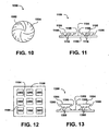
- FIG. 10 illustrates an exemplary pattern of solution placement that may adjust local wear rates to compensate for rotational velocity difference extending along a radius.
- the distance between lines near center 1002 is greater than the distance between lines near the outer edge 1004.
- prior art methods for forming engineered abrasive articles are generally limited to articles that have outer surfaces having good mold-release contours, such as positively sloping walls including pyramidal shapes and conical shapes.
- non-engineered coated abrasives are considered two-dimensional because the thickness of a given feature is small relative to the cross-section of that feature.
- engineered and structured abrasives and bonded abrasives have features that are significantly thick relative to the cross-section of the feature, presenting additional manufacturing considerations.
- rapid tooling methods described herein permit formation of abrasive articles having outer surface contours that generally have poor mold-release characteristics, such as negatively sloping walls and vertical walls.
- a negatively sloping wall has a contour that slopes inward toward the center of a structure with decreasing height and a positively sloping wall has a contour that slopes outward from the center of a structure with decreasing height.
- a pyramid has a positively sloping wall and an inverted pyramid has a negatively sloping wall.
- Vertical walls are also difficult to produce using traditional methods for forming engineered abrasives.
- the term "generally negative slope” is used to include negative sloping contours and vertical contours, wherein the abrasive structures have at least one wall having a slope that extends along an angle ⁇ (alpha) from -90° to 0° relative to a normal direction extending from the outer surface of the abrasive article.
- FIGs. 11 and 12 include illustrations of an engineered abrasive article 1100 that includes a pattern or array of abrasive structures 1102.
- the abrasive structures 1102 include negatively sloping walls 1106. As a result, the abrasive structures 1102 are wider on top than where they contact the substrate 1108. Such a contour has poor mold-release characteristics.
- FIG. 13 includes an illustration of an abrasive article 1300 that includes a pattern of abrasive structures 1304 formed over a substrate 1302.
- the abrasive structures 1304 have walls that include negatively sloping portions 1306.
- Rapid tooling methods also permit formation of microfeatures or integrated internal features within abrasive structures.
- rapid tooling methods allow formation of structured pores and channels within and on abrasive structures.
- the pattern of abrasive structures 1102 form macrochannels 1104 between the structures 1102. Rapid tooling methods allow the formation of microfeatures, such as structured channels, pores and cleavage planes.
- macrofeatures are features formed globally by the pattern of structures or between structures and microfeatures are features formed in or on the abrasive structures themselves.
- FIG. 11 illustrates microfeatures, such as internal structured pores 1110, within an abrasive structure 1102, and macrofeature channel 1104 is formed by the pattern of structures or between structures 1102.
- the abrasive article may include a repeated pattern of abrasive structures having a pattern of one or more internal structured pores.
- FIG. 13 illustrates internal structured pores 1308 within abrasive structures 1304.
- the internal structured pores may have precisely controlled dimensions and shapes.
- the internal structured pores have geometric cross-sections selected from a group consisting of polygonal, circular and irregular.
- Polygonal includes square, triangular, rectangular, rhomboid, trapezoidal, and pentagonal. Irregular shapes include, for example, "D" shaped, semicircular, and star-shaped.
- the internal structured pores may have dimensional variability not greater than about 50 microns, such as not greater than about 8 microns. Dimensional variability refers to variability of pore dimension within a set of abrasive structures.
- the internal structured pores may have locational variability (i.e.
- microfeature pores are internal to the structures.
- microfeature pores and channels may be formed in the outer contours of the structures.
- rapid tooling may produce abrasive structures with microfeatures, such as engineered cleavage planes.
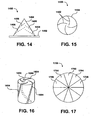
- the abrasive structure 1404 may include engineered cleavage planes 1406.
- the cleavage planes 1406 are not horizontal or vertical and terminate part way through a structure.
- the abrasive structure 1404 is designed to periodically cleave or fissure along a plane 1406, providing improved abrasion and sharper angles.
- Such cleavage planes 1406 may also be used to reduce surface area over which the abrasive contacts a surface, increasing the pressure exerted by the abrasive surface.
- the abrasive structure 1404 may be formed over a substrate 1402.
- the abrasive structure 1404 may be formed as a bonded abrasive structure.
- the concentration of abrasive particles within abrasive structures may be varied as a function of distance normal to the surface of a backing. For example, in a pyramidal structure, the concentration of abrasive particles may be higher nearer the backing and lower away from the backing.
- Rapid tooling techniques may also be used to form bonded abrasive articles.
- rapid tooling techniques can be used to form abrasive articles having microfeatures and poor mold release contours.
- cutting fluid channels 1502 may be formed in a cylindrical or wheel-shaped bonded abrasive article 1500.
- the cutting fluid channels 1502 is a helical structure that is designed to encourage flow of cutting fluid through the channels 1502 to grind surface 1504 during usage.
- FIG. 16 An alternative embodiment is illustrated in FIG. 16 in which a bonded abrasive article includes a cutting fluid channel 1602 and swarf channels 1604.
- the cutting fluid channel 1602 is designed to facilitate flow of the cutting fluid to surface 1600 and swarf channels 1604 are designed to remove swarf material from the surface 1600 when the abrasive article is in use.
- the swarf channels 1604 have curved cross sections and cross sections that are not straight and, as a result, the contour of the abrasive article 1600 has poor mold-release characteristics.
- the abrasive article includes a feature, such as a swarf channel 1604, extending into the bonded abrasive article from the outer surface of the bonded abrasive article.
- the feature has a feature aspect ratio at least about 1.5, wherein the feature aspect ratio is the depth of the feature extending inwardly from the outer surface to a minimum feature opening dimension at the outer surface of the bonded abrasive article.
- the feature aspect ratio may be at least about 2.5, such as at least about 3.5.
- abrasive articles that include cutting fluid channels allow delivery of cooling fluids and lubricants to grind interfaces.
- Typical prior art systems direct cooling fluid to grind interfaces through external tubes.
- the fluid often does not sufficiently lubricate or coat the surface.
- the surface may be excessively hot and may include excess swarf, resulting in poor material removal rates and surface quality.
- particular embodiments of the abrasive articles described herein include cutting fluid channels that deliver cooling and lubricating fluids directly to the grinding interface.
- such cutting fluid channels may be shaped to force fluid onto the surface with movement (e.g. rotation) of the abrasive article and may be shaped to allow delivery of cutting fluid even as the abrasive article experiences wear.
- a bonded abrasive article may include regions having different abrasive particles or different concentrations of abrasive particles.
- a cylindrical or wheel shaped bonded abrasive article 1700 may include regions, such as regions 1702, 1704, and 1706, having different abrasive characteristics, such as particle density, porosity, bond strength, elastic modulus, and compressive modulus.
- region 1702 may have one concentration of abrasive particles and region 1704 may have a different concentration.
- the different regions (1702, 1704, and 1706) may be formed using different abrasive solutions or by applying abrasive solutions in different proportions.
- the regions may vary based on distance from the center of an abrasive article, as illustrated in FIG. 18 .
- Different regions e.g. 1802, 1804, 1806, and 1810
- the concentration of abrasive particles may be locally controlled based on distance from center or based on desired wear patterns within the article.
- Such a bonded abrasive article may have patterned layers wherein, within a layer, a first region has a first composition and a second region has a second composition different from the first composition.
- FIG. 19 includes an illustrative example including several features, such as cleavage planes and variations in composition.
- the abrasive article 1900 includes compositions 1902, 1910, 1912, and 1914.
- the article 1900 also includes cleavage planes 1906.
- the article periodically cleaves at cleavage planes 1906, exposing an abrasive surface, such as abrasive surface 1908.
- the abrasive surface 1908 has a surface area approximately equal to the initial abrasive surface 1904.
- the abrasive composition 1902 has high bond strength.
- the other material compositions 1910, 1912 and 1914 function to support the abrasive surface when forces are applied normal to the abrasive surface.
- the other material compositions 1910, 1912, and 1914 may vary in bond strength, elasticity, abrasive quality, and wear rate.
- the rapid tooling system and the rapid structuring media cartridge can be adapted to form three-dimensional abrasive structures that include features selected from the group consisting of microfeatures, three-dimensional abrasive features, a pattern of cutting fluid channels, a pattern of swarf channels, a pattern of internal voids, and oriented breakage planes.
- the rapid tooling system and removable cartridge may be used to provide on-demand manufacturing capabilities for consumers of abrasive articles.
- Such on-demand tooling allows consumers to reduce inventory of abrasive articles and insures a ready supply of such articles.
- a coated abrasive article may be produced by coating a limited area of an underlying substrate. In this manner, only the regions useful in making or producing the coated abrasive article are coated with abrasive and binder, whereas other regions are left uncoated. In such a case, use of abrasive and binder is reduced.
- rapid tooling and removable cartridges for abrasive articles reduces the likelihood of contamination of an abrasive article with abrasive particles from an alternate run of abrasive articles.
- Consumers may be supplied with a cartridge that includes the solution, powder, or filament having only those abrasive particles and abrasive particle sizes in which the consumer is interested. By selection of a particular binder solution and a desired abrasive particle, the consumer can produce a desired abrasive article without contamination or mess.
- Rapid tooling systems for producing abrasive articles are particularly adapted to form abrasive articles for fining and polishing applications.
- such systems provide for on-demand production of single use fining abrasives for applications, such as the ophthalmic lens production and electronics production.
- Abrasive particles for such applications may have an average particle size about 3-5 micron and build layers as fine as about 16 microns.
- Such systems may also be useful in producing abrasive articles for polishing, such as jewelry applications and polished sample preparation, and paint removal applications.
- Consumer-side manufacturing of abrasive articles may be facilitated by providing a consumer with a rapid tooling system and cartridges filled with abrasive compositions.
- the consumer may be an internal consumer of abrasive articles, such as a consumer that uses abrasive articles and produces the abrasive articles for internal consumption.
- the consumer may manufacture abrasive articles for sale and distribution.
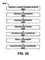
- a rapid tooling system is provided to a customer, as illustrated at 2002.
- a rapid tooling system for manufacturing abrasive articles may be leased or sold to a consumer of abrasive materials.
- the rapid tooling system for producing the abrasive article may be loaned or given to a prospective consumer.
- a cartridge including abrasive particles and binder is provided to the consumer, as illustrated at 2004.
- a consumer may select a particular binder and particle grain size or grain type of abrasive particle.
- the abrasive solution manufacturer may provide a cartridge having a solution having the particular binder and the desired abrasive particles, directly or indirectly, to the consumer.
- the consumer may purchase the cartridge.
- the consumer may purchase the solution, powder or filaments provided in the cartridge.
- a substrate When configured to form coated and engineered abrasive articles, a substrate may be provided, as illustrated at 2005.
- the substrate may be selected from the group consisting of paper, film, fabric, foil, and foam.
- the rapid tooling system may be configured to deposit successive layers of abrasive particles and binder over the substrate to form an abrasive article using the cartridge.
- the consumer may be provided with computer-implemented instructions and software operable by the rapid tooling system to control deposition of the first binder and the first abrasive particles in the successive patterned layers, as illustrated at 2006.
- the consumer may be provided with software and data configured to instruct the rapid tooling system to form a particular abrasive structure design.
- a consumer utilizes the cartridge and the rapid tooling system to manufacture the desired abrasive articles. In so doing, the cartridge is depleted of its solution, powder or filaments. In one exemplary embodiment, a manufacturer or a service provider directly or indirectly retrieves the used cartridge, as illustrated at 2007.
- the consumer may send the cartridge to the service provider or manufacturer.
- the cartridge may be provided in a package configurable for sending the cartridge to the service provider or manufacturer.
- the cartridge may be sent by a mail carrier, such the US Postal Service®, FedEx®, or UPS® in a package.
- the package may include a return address and return postage area.
- the consumer may reconfigure the package for return, insert the cartridge and send it via the mail carrier.
- the cartridge may include a unique identifier.
- the consumer may log on to a website, provide the unique identifier, and specify the type of binders and abrasive particles desired.
- the manufacturer sends a second cartridge with the desired binders and abrasive particles.
- the manufacturer or service provider refills the cartridge with the desired binder and abrasive particles, as illustrated at 2008. However, if the cartridge is worn or inoperable, the cartridge may be replaced.
- the service provider or manufacturer directly or indirectly provides the refilled cartridge, as illustrated at 2010, to a consumer, such as to the consumer from which the cartridge was retrieved or to a different consumer.
- the service provider or manufacturer may send the cartridge via a mail carrier in a returnable package
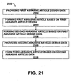
- the rapid tooling system and removable cartridge may be used to produce one or more designs of abrasive articles.
- a consumer of abrasive articles provides design data for a first abrasive article design to the rapid tooling system, as illustrated at 2102.
- the consumer then forms a first abrasive article based on the first abrasive article design data, as illustrated at 2104, and may optionally produce additional abrasive articles, such as a second abrasive article, based on the first abrasive article design data, as illustrated at 2106.
- the consumer may provide another set of design data for a second abrasive article design, as illustrated at 2108, and may subsequently form a third abrasive article based on the second abrasive article design data, as illustrated at step 2110.
- a consumer may exchange cartridges having different compositions in and out of the rapid tooling system to produce abrasive articles having different performance characteristics. For example, a consumer may select a cartridge based on the mechanical strength of the binder, based on the particle size and wear resistance of the abrasive particles, or based on the wear resistance of the cured binder and abrasive particle solution. The consumer can place the selected cartridge into the rapid tooling system to produce the abrasive article having the desired performance characteristics. Empty cartridges may be provided to a service provider or manufacturer for refilling.
Applications Claiming Priority (2)
| Application Number | Priority Date | Filing Date | Title |
|---|---|---|---|
| US11/062,904 US7524345B2 (en) | 2005-02-22 | 2005-02-22 | Rapid tooling system and methods for manufacturing abrasive articles |
| PCT/US2006/005915 WO2006091519A2 (en) | 2005-02-22 | 2006-02-21 | Coated or bonded abrasive articles |
Publications (2)
| Publication Number | Publication Date |
|---|---|
| EP1851005A2 EP1851005A2 (en) | 2007-11-07 |
| EP1851005B1 true EP1851005B1 (en) | 2009-06-10 |
Family
ID=36570545
Family Applications (1)
| Application Number | Title | Priority Date | Filing Date |
|---|---|---|---|
| EP06735533A Not-in-force EP1851005B1 (en) | 2005-02-22 | 2006-02-21 | Coated abrasive articles |
Country Status (18)
| Country | Link |
|---|---|
| US (1) | US7524345B2 (zh) |
| EP (1) | EP1851005B1 (zh) |
| JP (1) | JP5260966B2 (zh) |
| KR (1) | KR100917572B1 (zh) |
| CN (1) | CN101142055B (zh) |
| AT (1) | ATE433365T1 (zh) |
| AU (1) | AU2006216846B2 (zh) |
| BR (1) | BRPI0606961A2 (zh) |
| CA (1) | CA2596700C (zh) |
| DE (1) | DE602006007215D1 (zh) |
| IL (1) | IL185294A (zh) |
| MX (1) | MX2007010255A (zh) |
| NO (1) | NO20073996L (zh) |
| NZ (1) | NZ560233A (zh) |
| RU (1) | RU2361719C2 (zh) |
| UA (1) | UA89224C2 (zh) |
| WO (1) | WO2006091519A2 (zh) |
| ZA (1) | ZA200706795B (zh) |
Cited By (1)
| Publication number | Priority date | Publication date | Assignee | Title |
|---|---|---|---|---|
| EP3313614A4 (en) * | 2015-06-25 | 2019-05-15 | 3M Innovative Properties Company | ABRASIVE ARTICLES WITH VITRIFIED BINDER AND METHODS OF MAKING SAME |
Families Citing this family (90)
| Publication number | Priority date | Publication date | Assignee | Title |
|---|---|---|---|---|
| US8034137B2 (en) * | 2007-12-27 | 2011-10-11 | 3M Innovative Properties Company | Shaped, fractured abrasive particle, abrasive article using same and method of making |
| US8123828B2 (en) * | 2007-12-27 | 2012-02-28 | 3M Innovative Properties Company | Method of making abrasive shards, shaped abrasive particles with an opening, or dish-shaped abrasive particles |
| US8142891B2 (en) * | 2008-12-17 | 2012-03-27 | 3M Innovative Properties Company | Dish-shaped abrasive particles with a recessed surface |
| US8142532B2 (en) * | 2008-12-17 | 2012-03-27 | 3M Innovative Properties Company | Shaped abrasive particles with an opening |
| WO2010077509A1 (en) * | 2008-12-17 | 2010-07-08 | 3M Innovative Properties Company | Shaped abrasive particles with grooves |
| US10137556B2 (en) * | 2009-06-22 | 2018-11-27 | 3M Innovative Properties Company | Shaped abrasive particles with low roundness factor |
| US8142531B2 (en) | 2008-12-17 | 2012-03-27 | 3M Innovative Properties Company | Shaped abrasive particles with a sloping sidewall |
| US8480772B2 (en) | 2009-12-22 | 2013-07-09 | 3M Innovative Properties Company | Transfer assisted screen printing method of making shaped abrasive particles and the resulting shaped abrasive particles |
| CN102695573B (zh) * | 2010-01-07 | 2015-05-06 | Gkn烧结金属有限公司 | 加工刀具和用于制造加工刀具的方法 |
| US9039797B2 (en) | 2010-11-01 | 2015-05-26 | 3M Innovative Properties Company | Shaped abrasive particles and method of making |
| RU2013135445A (ru) | 2010-12-31 | 2015-02-10 | Сэнт-Гобэн Керамикс Энд Пластикс, Инк. | Абразивное изделие (варианты) и способ его формования |
| TWI471196B (zh) * | 2011-03-31 | 2015-02-01 | Saint Gobain Abrasives Inc | 用於高速磨削操作之磨料物品 |
| US8840694B2 (en) | 2011-06-30 | 2014-09-23 | Saint-Gobain Ceramics & Plastics, Inc. | Liquid phase sintered silicon carbide abrasive particles |
| CN108262695A (zh) | 2011-06-30 | 2018-07-10 | 圣戈本陶瓷及塑料股份有限公司 | 包括氮化硅磨粒的磨料制品 |
| CN103826802B (zh) | 2011-09-26 | 2018-06-12 | 圣戈本陶瓷及塑料股份有限公司 | 包括磨料颗粒材料的磨料制品,使用磨料颗粒材料的涂布磨料及其形成方法 |
| JP6033886B2 (ja) | 2011-12-30 | 2016-11-30 | サン−ゴバン セラミックス アンド プラスティクス,インコーポレイティド | 成形研磨粒子および同粒子を形成する方法 |
| EP2798032A4 (en) | 2011-12-30 | 2015-12-23 | Saint Gobain Ceramics | MANUFACTURE OF SHAPED GRINDING PARTICLES |
| EP3851248B1 (en) | 2011-12-30 | 2024-04-03 | Saint-Gobain Ceramics & Plastics, Inc. | Composite shaped abrasive particles and method of forming same |
| CA3170246A1 (en) | 2012-01-10 | 2013-07-18 | Saint-Gobain Ceramics & Plastics, Inc. | Abrasive particles having complex shapes and methods of forming same |
| WO2013106602A1 (en) | 2012-01-10 | 2013-07-18 | Saint-Gobain Ceramics & Plastics, Inc. | Abrasive particles having particular shapes and methods of forming such particles |
| WO2013149209A1 (en) | 2012-03-30 | 2013-10-03 | Saint-Gobain Abrasives, Inc. | Abrasive products having fibrillated fibers |
| BR112014024937B1 (pt) | 2012-04-04 | 2021-01-12 | 3M Innovative Properties Company | partícula abrasiva conformada de cerâmica, pluralidade de partículas abrasivas, artigo abrasivo e método para produzir partículas abrasivas conformadas de cerâmica |
| US9067299B2 (en) | 2012-04-25 | 2015-06-30 | Applied Materials, Inc. | Printed chemical mechanical polishing pad |
| US9200187B2 (en) | 2012-05-23 | 2015-12-01 | Saint-Gobain Ceramics & Plastics, Inc. | Shaped abrasive particles and methods of forming same |
| US10106714B2 (en) | 2012-06-29 | 2018-10-23 | Saint-Gobain Ceramics & Plastics, Inc. | Abrasive particles having particular shapes and methods of forming such particles |
| JP5982580B2 (ja) | 2012-10-15 | 2016-08-31 | サンーゴバン アブレイシブズ,インコーポレイティド | 特定の形状を有する研磨粒子およびこのような粒子の形成方法 |
| EP2938459B1 (en) | 2012-12-31 | 2021-06-16 | Saint-Gobain Ceramics & Plastics, Inc. | Particulate materials and methods of forming same |
| CA2907372C (en) | 2013-03-29 | 2017-12-12 | Saint-Gobain Abrasives, Inc. | Abrasive particles having particular shapes and methods of forming such particles |
| TW201502263A (zh) | 2013-06-28 | 2015-01-16 | Saint Gobain Ceramics | 包含成形研磨粒子之研磨物品 |
| CN110591645A (zh) | 2013-09-30 | 2019-12-20 | 圣戈本陶瓷及塑料股份有限公司 | 成形磨粒及其形成方法 |
| US9421666B2 (en) * | 2013-11-04 | 2016-08-23 | Applied Materials, Inc. | Printed chemical mechanical polishing pad having abrasives therein |
| US9566689B2 (en) | 2013-12-31 | 2017-02-14 | Saint-Gobain Abrasives, Inc. | Abrasive article including shaped abrasive particles |
| US9771507B2 (en) | 2014-01-31 | 2017-09-26 | Saint-Gobain Ceramics & Plastics, Inc. | Shaped abrasive particle including dopant material and method of forming same |
| MX2016013465A (es) | 2014-04-14 | 2017-02-15 | Saint-Gobain Ceram & Plastics Inc | Articulo abrasivo que incluye particulas abrasivas conformadas. |
| CN110055032A (zh) | 2014-04-14 | 2019-07-26 | 圣戈本陶瓷及塑料股份有限公司 | 包括成形磨粒的研磨制品 |
| WO2015184355A1 (en) | 2014-05-30 | 2015-12-03 | Saint-Gobain Abrasives, Inc. | Method of using an abrasive article including shaped abrasive particles |
| US9873180B2 (en) | 2014-10-17 | 2018-01-23 | Applied Materials, Inc. | CMP pad construction with composite material properties using additive manufacturing processes |
| US10399201B2 (en) | 2014-10-17 | 2019-09-03 | Applied Materials, Inc. | Advanced polishing pads having compositional gradients by use of an additive manufacturing process |
| US10875153B2 (en) | 2014-10-17 | 2020-12-29 | Applied Materials, Inc. | Advanced polishing pad materials and formulations |
| US10875145B2 (en) | 2014-10-17 | 2020-12-29 | Applied Materials, Inc. | Polishing pads produced by an additive manufacturing process |
| US9776361B2 (en) | 2014-10-17 | 2017-10-03 | Applied Materials, Inc. | Polishing articles and integrated system and methods for manufacturing chemical mechanical polishing articles |
| US11745302B2 (en) | 2014-10-17 | 2023-09-05 | Applied Materials, Inc. | Methods and precursor formulations for forming advanced polishing pads by use of an additive manufacturing process |
| US10821573B2 (en) | 2014-10-17 | 2020-11-03 | Applied Materials, Inc. | Polishing pads produced by an additive manufacturing process |
| WO2016060712A1 (en) * | 2014-10-17 | 2016-04-21 | Applied Materials, Inc. | Cmp pad construction with composite material properties using additive manufacturing processes |
| US9914864B2 (en) | 2014-12-23 | 2018-03-13 | Saint-Gobain Ceramics & Plastics, Inc. | Shaped abrasive particles and method of forming same |
| US9707529B2 (en) | 2014-12-23 | 2017-07-18 | Saint-Gobain Ceramics & Plastics, Inc. | Composite shaped abrasive particles and method of forming same |
| US9676981B2 (en) | 2014-12-24 | 2017-06-13 | Saint-Gobain Ceramics & Plastics, Inc. | Shaped abrasive particle fractions and method of forming same |
| TWI634200B (zh) | 2015-03-31 | 2018-09-01 | 聖高拜磨料有限公司 | 固定磨料物品及其形成方法 |
| US10196551B2 (en) | 2015-03-31 | 2019-02-05 | Saint-Gobain Abrasives, Inc. | Fixed abrasive articles and methods of forming same |
| CA2988012C (en) | 2015-06-11 | 2021-06-29 | Saint-Gobain Ceramics & Plastics, Inc. | Abrasive article including shaped abrasive particles |
| WO2016209696A1 (en) | 2015-06-25 | 2016-12-29 | 3M Innovative Properties Company | Methods of making metal bond abrasive articles and metal bond abrasive articles |
| GB2540385B (en) * | 2015-07-15 | 2017-10-11 | C4 Carbides Ltd | Improvements in or relating to tool blades and their manufacture |
| GB2540476A (en) * | 2015-07-15 | 2017-01-18 | C4 Carbides Ltd | Improvements in or relating to tool blades and their manufacture |
| TWI695752B (zh) * | 2015-10-16 | 2020-06-11 | 美商應用材料股份有限公司 | 用於以積層製程形成先進拋光墊的配方 |
| CN108290267B (zh) | 2015-10-30 | 2021-04-20 | 应用材料公司 | 形成具有期望ζ电位的抛光制品的设备与方法 |
| US10391605B2 (en) | 2016-01-19 | 2019-08-27 | Applied Materials, Inc. | Method and apparatus for forming porous advanced polishing pads using an additive manufacturing process |
| JP6926094B2 (ja) * | 2016-01-21 | 2021-08-25 | スリーエム イノベイティブ プロパティズ カンパニー | メタルボンド及びガラス質ボンド研磨物品の製造方法、並びに研磨物品前駆体 |
| EP3405503B1 (en) | 2016-01-21 | 2021-11-17 | 3M Innovative Properties Company | Additive processing of fluoropolymers |
| WO2017156342A1 (en) | 2016-03-09 | 2017-09-14 | Applied Materials, Inc. | Correction of fabricated shapes in additive manufacturing |
| JP7010566B2 (ja) * | 2016-03-30 | 2022-01-26 | スリーエム イノベイティブ プロパティズ カンパニー | メタルボンド及びガラス質ボンド研磨物品の製造方法、並びに研磨物品前駆体 |
| KR102313436B1 (ko) | 2016-05-10 | 2021-10-19 | 생-고뱅 세라믹스 앤드 플라스틱스, 인코포레이티드 | 연마 입자들 및 그 형성 방법 |
| KR102243356B1 (ko) | 2016-05-10 | 2021-04-23 | 생-고뱅 세라믹스 앤드 플라스틱스, 인코포레이티드 | 연마 입자 및 이의 형성 방법 |
| CN105950115A (zh) * | 2016-05-13 | 2016-09-21 | 盐城工学院 | 一种适用于氧化镓衬底的环保研磨膏及其制备方法 |
| US10500786B2 (en) | 2016-06-22 | 2019-12-10 | Carbon, Inc. | Dual cure resins containing microwave absorbing materials and methods of using the same |
| US20180009032A1 (en) * | 2016-07-08 | 2018-01-11 | General Electric Company | Metal objects and methods for making metal objects using disposable molds |
| US20180079153A1 (en) | 2016-09-20 | 2018-03-22 | Applied Materials, Inc. | Control of dispensing operations for additive manufacturing of a polishing pad |
| EP4349896A2 (en) | 2016-09-29 | 2024-04-10 | Saint-Gobain Abrasives, Inc. | Fixed abrasive articles and methods of forming same |
| CN108015906A (zh) | 2016-10-28 | 2018-05-11 | 圣戈班磨料磨具有限公司 | 空芯钻头及其制造方法 |
| WO2018118566A1 (en) | 2016-12-23 | 2018-06-28 | 3M Innovative Properties Company | Polymer bond abrasive articles and methods of making them |
| US10563105B2 (en) | 2017-01-31 | 2020-02-18 | Saint-Gobain Ceramics & Plastics, Inc. | Abrasive article including shaped abrasive particles |
| US10759024B2 (en) | 2017-01-31 | 2020-09-01 | Saint-Gobain Ceramics & Plastics, Inc. | Abrasive article including shaped abrasive particles |
| US10596763B2 (en) * | 2017-04-21 | 2020-03-24 | Applied Materials, Inc. | Additive manufacturing with array of energy sources |
| US11059149B2 (en) | 2017-05-25 | 2021-07-13 | Applied Materials, Inc. | Correction of fabricated shapes in additive manufacturing using initial layer |
| US10967482B2 (en) | 2017-05-25 | 2021-04-06 | Applied Materials, Inc. | Fabrication of polishing pad by additive manufacturing onto mold |
| DE102017113369A1 (de) * | 2017-06-19 | 2018-12-20 | Carl Hilzinger-Thum Gmbh & Co. Kg | Verfahren zum Herstellen einer Schleifbürste sowie eine nach diesem Verfahren hergestellte Schleifbürste |
| CN110719946B (zh) | 2017-06-21 | 2022-07-15 | 圣戈本陶瓷及塑料股份有限公司 | 颗粒材料及其形成方法 |
| US11471999B2 (en) | 2017-07-26 | 2022-10-18 | Applied Materials, Inc. | Integrated abrasive polishing pads and manufacturing methods |
| WO2019032286A1 (en) | 2017-08-07 | 2019-02-14 | Applied Materials, Inc. | ABRASIVE DISTRIBUTION POLISHING PADS AND METHODS OF MAKING SAME |
| US11607775B2 (en) | 2017-11-21 | 2023-03-21 | 3M Innovative Properties Company | Coated abrasive disc and methods of making and using the same |
| US11597059B2 (en) | 2017-11-21 | 2023-03-07 | 3M Innovative Properties Company | Coated abrasive disc and methods of making and using the same |
| KR20210042171A (ko) | 2018-09-04 | 2021-04-16 | 어플라이드 머티어리얼스, 인코포레이티드 | 진보한 폴리싱 패드들을 위한 제형들 |
| EP3999280A1 (en) * | 2019-07-15 | 2022-05-25 | 3M Innovative Properties Company | Abrasive articles having internal coolant features and methods of manufacturing the same |
| JP7105743B2 (ja) * | 2019-08-09 | 2022-07-25 | 株式会社ノリタケカンパニーリミテド | 研磨体の製造方法 |
| US11813712B2 (en) | 2019-12-20 | 2023-11-14 | Applied Materials, Inc. | Polishing pads having selectively arranged porosity |
| KR20220116556A (ko) | 2019-12-27 | 2022-08-23 | 세인트-고바인 세라믹스 앤드 플라스틱스, 인크. | 연마 물품 및 이의 형성 방법 |
| US11806829B2 (en) | 2020-06-19 | 2023-11-07 | Applied Materials, Inc. | Advanced polishing pads and related polishing pad manufacturing methods |
| US11878389B2 (en) | 2021-02-10 | 2024-01-23 | Applied Materials, Inc. | Structures formed using an additive manufacturing process for regenerating surface texture in situ |
| WO2023280872A1 (en) | 2021-07-05 | 2023-01-12 | Admatec Europe B.V. | Additive manufacturing method and apparatus for abrasive articles |
| CN114274060B (zh) * | 2021-11-23 | 2023-12-01 | 北京安泰钢研超硬材料制品有限责任公司 | 一种SiC芯片减薄用金属基金刚石刀头、砂轮及其制造方法 |
| DE102022126743A1 (de) * | 2022-10-13 | 2024-04-18 | Ernst-Abbe-Hochschule Jena Körperschaft des öffentlichen Rechts | Werkzeug zum Materialabtrag und Verfahren zu seiner Herstellung |
Family Cites Families (59)
| Publication number | Priority date | Publication date | Assignee | Title |
|---|---|---|---|---|
| US3058223A (en) * | 1960-02-02 | 1962-10-16 | Westinghouse Electric Corp | Pulse actuated measuring apparatus |
| DD223654A1 (de) | 1984-05-21 | 1985-06-19 | Werkzeugmasch Okt Veb | Schleifkoerper, vorzugsweise doppelkegelschleifkoerper |
| JP2626982B2 (ja) * | 1987-10-19 | 1997-07-02 | 東京磁気印刷株式会社 | 研磨フィルム |
| JPH0716888B2 (ja) * | 1989-03-20 | 1995-03-01 | 日本レヂボン株式会社 | 研削研磨用砥石とその製造方法とその製造装置 |
| JPH06104816B2 (ja) * | 1990-02-09 | 1994-12-21 | 日本研磨材工業株式会社 | 焼結アルミナ砥粒及びその製造方法 |
| JPH0749165B2 (ja) * | 1990-04-26 | 1995-05-31 | 新日本製鐵株式会社 | 耐衝撃性に優れる被覆超硬合金工具 |
| US5243790A (en) * | 1992-06-25 | 1993-09-14 | Abrasifs Vega, Inc. | Abrasive member |
| JP3360339B2 (ja) * | 1993-01-28 | 2002-12-24 | 住友電気工業株式会社 | 被覆切削工具 |
| KR0165625B1 (ko) | 1993-06-02 | 1999-02-01 | 기타지마 요시토시 | 연마테이프 및 그 제조방법 |
| EP0702615B1 (en) * | 1993-06-17 | 1997-10-22 | Minnesota Mining And Manufacturing Company | Patterned abrading articles and methods making and using same |
| US5477025A (en) * | 1994-01-14 | 1995-12-19 | Quantum Laser Corporation | Laser nozzle |
| US5731046A (en) * | 1994-01-18 | 1998-03-24 | Qqc, Inc. | Fabrication of diamond and diamond-like carbon coatings |
| US5554415A (en) * | 1994-01-18 | 1996-09-10 | Qqc, Inc. | Substrate coating techniques, including fabricating materials on a surface of a substrate |
| US6209420B1 (en) * | 1994-03-16 | 2001-04-03 | Baker Hughes Incorporated | Method of manufacturing bits, bit components and other articles of manufacture |
| GB9423268D0 (en) * | 1994-11-18 | 1995-01-11 | Minnesota Mining & Mfg | Abrasive articles |
| JP3117394B2 (ja) * | 1994-11-29 | 2000-12-11 | 帝人製機株式会社 | 光学的立体造形用樹脂組成物 |
| US5571297A (en) * | 1995-06-06 | 1996-11-05 | Norton Company | Dual-cure binder system |
| KR0158750B1 (ko) * | 1995-06-09 | 1999-01-15 | 김수광 | 연마용 시트 |
| JP3572722B2 (ja) * | 1995-06-15 | 2004-10-06 | 住友電気工業株式会社 | 被覆硬質合金工具 |
| US5669940A (en) * | 1995-08-09 | 1997-09-23 | Minnesota Mining And Manufacturing Company | Abrasive article |
| US5785914A (en) * | 1995-11-22 | 1998-07-28 | Kress; Russel L. | Process of producing ceramic polymer composite tool |
| US5738817A (en) * | 1996-02-08 | 1998-04-14 | Rutgers, The State University | Solid freeform fabrication methods |
| US5742883A (en) * | 1996-07-31 | 1998-04-21 | Hewlett-Packard Company | Product integrated return mailer |
| US5902441A (en) * | 1996-09-04 | 1999-05-11 | Z Corporation | Method of three dimensional printing |
| US6007318A (en) * | 1996-12-20 | 1999-12-28 | Z Corporation | Method and apparatus for prototyping a three-dimensional object |
| US6110031A (en) * | 1997-06-25 | 2000-08-29 | 3M Innovative Properties Company | Superabrasive cutting surface |
| US6203861B1 (en) * | 1998-01-12 | 2001-03-20 | University Of Central Florida | One-step rapid manufacturing of metal and composite parts |
| KR19990081117A (ko) * | 1998-04-25 | 1999-11-15 | 윤종용 | 씨엠피 패드 컨디셔닝 디스크 및 컨디셔너, 그 디스크의 제조방법, 재생방법 및 세정방법 |
| AU4849899A (en) * | 1998-06-30 | 2000-01-17 | Trustees Of Tufts College | Multiple-material prototyping by ultrasonic adhesion |
| US20020077037A1 (en) * | 1999-05-03 | 2002-06-20 | Tietz James V. | Fixed abrasive articles |
| US6319108B1 (en) * | 1999-07-09 | 2001-11-20 | 3M Innovative Properties Company | Metal bond abrasive article comprising porous ceramic abrasive composites and method of using same to abrade a workpiece |
| US6375692B1 (en) | 1999-07-29 | 2002-04-23 | Saint-Gobain Abrasives Technology Company | Method for making microabrasive tools |
| US6328632B1 (en) * | 1999-08-31 | 2001-12-11 | Micron Technology, Inc. | Polishing pads and planarizing machines for mechanical and/or chemical-mechanical planarization of microelectronic substrate assemblies |
| US6293980B2 (en) * | 1999-12-20 | 2001-09-25 | Norton Company | Production of layered engineered abrasive surfaces |
| US7016868B1 (en) * | 1999-12-22 | 2006-03-21 | Eastman Kodak Company | Method and system for organizing images |
| US20010046834A1 (en) | 2000-02-28 | 2001-11-29 | Anuradha Ramana | Pad surface texture formed by solid phase droplets |
| US20010039175A1 (en) * | 2000-02-29 | 2001-11-08 | Reza Golzarian | Polishing pad surface on hollow posts |
| JP4219077B2 (ja) * | 2000-03-15 | 2009-02-04 | 株式会社ティ・ケー・エックス | ディスク状砥石 |
| AU2001275164A1 (en) * | 2000-06-01 | 2001-12-11 | Board Of Regents, The University Of Texas System | Direct selective laser sintering of metals |
| JP2002057130A (ja) | 2000-08-14 | 2002-02-22 | Three M Innovative Properties Co | Cmp用研磨パッド |
| US6652256B2 (en) * | 2000-10-27 | 2003-11-25 | Dorsey D. Coe | Three-dimensional model colorization during model construction from computer aided design data |
| US20020090901A1 (en) * | 2000-11-03 | 2002-07-11 | 3M Innovative Properties Company | Flexible abrasive product and method of making and using the same |
| KR100497205B1 (ko) * | 2001-08-02 | 2005-06-23 | 에스케이씨 주식회사 | 마이크로홀이 형성된 화학적 기계적 연마패드 |
| US6632129B2 (en) * | 2001-02-15 | 2003-10-14 | 3M Innovative Properties Company | Fixed abrasive article for use in modifying a semiconductor wafer |
| US6767619B2 (en) * | 2001-05-17 | 2004-07-27 | Charles R. Owens | Preform for manufacturing a material having a plurality of voids and method of making the same |
| US20020188504A1 (en) * | 2001-06-07 | 2002-12-12 | Whale Margo N. | Monitoring usage of printer consumables to initiate promotional actions |
| US6599177B2 (en) * | 2001-06-25 | 2003-07-29 | Saint-Gobain Abrasives Technology Company | Coated abrasives with indicia |
| CN1328009C (zh) * | 2001-08-02 | 2007-07-25 | 株式会社Skc | 利用激光制造化学机械抛光垫的方法 |
| JP2003080465A (ja) * | 2001-09-10 | 2003-03-18 | Refuraito Kk | ラッピングフィルム及びその製造方法 |
| TW526817U (en) * | 2001-12-25 | 2003-04-01 | Ind Tech Res Inst | Pressure regulating apparatus and ink jet printing head using the pressurized regulating apparatus |
| US6949128B2 (en) * | 2001-12-28 | 2005-09-27 | 3M Innovative Properties Company | Method of making an abrasive product |
| JP4097456B2 (ja) * | 2002-05-09 | 2008-06-11 | シャープ株式会社 | 画像形成装置の梱包具及び画像形成装置の梱包方法 |
| US6797023B2 (en) * | 2002-05-14 | 2004-09-28 | Saint-Gobain Abrasives Technology Company | Coated abrasives |
| US6833014B2 (en) * | 2002-07-26 | 2004-12-21 | 3M Innovative Properties Company | Abrasive product, method of making and using the same, and apparatus for making the same |
| US7179526B2 (en) * | 2002-08-02 | 2007-02-20 | 3M Innovative Properties Company | Plasma spraying |
| US7261752B2 (en) * | 2002-09-24 | 2007-08-28 | Chien-Min Sung | Molten braze-coated superabrasive particles and associated methods |
| JP2004338022A (ja) * | 2003-05-14 | 2004-12-02 | Tkx:Kk | ディスク砥石およびその製造方法 |
| US20050060941A1 (en) * | 2003-09-23 | 2005-03-24 | 3M Innovative Properties Company | Abrasive article and methods of making the same |
| US7270143B2 (en) * | 2005-03-16 | 2007-09-18 | The General Electric Company | Offset variable-orifice flow sensor |
-
2005
- 2005-02-22 US US11/062,904 patent/US7524345B2/en not_active Expired - Fee Related
-
2006
- 2006-02-21 BR BRPI0606961-4A patent/BRPI0606961A2/pt not_active IP Right Cessation
- 2006-02-21 UA UAA200710574A patent/UA89224C2/ru unknown
- 2006-02-21 RU RU2007134984A patent/RU2361719C2/ru not_active IP Right Cessation
- 2006-02-21 JP JP2007557079A patent/JP5260966B2/ja not_active Expired - Fee Related
- 2006-02-21 CN CN2006800054838A patent/CN101142055B/zh not_active Expired - Fee Related
- 2006-02-21 MX MX2007010255A patent/MX2007010255A/es active IP Right Grant
- 2006-02-21 CA CA2596700A patent/CA2596700C/en not_active Expired - Fee Related
- 2006-02-21 AT AT06735533T patent/ATE433365T1/de not_active IP Right Cessation
- 2006-02-21 WO PCT/US2006/005915 patent/WO2006091519A2/en active Application Filing
- 2006-02-21 NZ NZ560233A patent/NZ560233A/en not_active IP Right Cessation
- 2006-02-21 EP EP06735533A patent/EP1851005B1/en not_active Not-in-force
- 2006-02-21 AU AU2006216846A patent/AU2006216846B2/en not_active Ceased
- 2006-02-21 KR KR1020077018832A patent/KR100917572B1/ko not_active IP Right Cessation
- 2006-02-21 DE DE602006007215T patent/DE602006007215D1/de not_active Expired - Fee Related
-
2007
- 2007-08-01 NO NO20073996A patent/NO20073996L/no not_active Application Discontinuation
- 2007-08-15 ZA ZA200706795A patent/ZA200706795B/xx unknown
- 2007-08-15 IL IL185294A patent/IL185294A/en not_active IP Right Cessation
Cited By (1)
| Publication number | Priority date | Publication date | Assignee | Title |
|---|---|---|---|---|
| EP3313614A4 (en) * | 2015-06-25 | 2019-05-15 | 3M Innovative Properties Company | ABRASIVE ARTICLES WITH VITRIFIED BINDER AND METHODS OF MAKING SAME |
Also Published As
| Publication number | Publication date |
|---|---|
| ZA200706795B (en) | 2008-10-29 |
| CA2596700C (en) | 2012-04-17 |
| KR100917572B1 (ko) | 2009-09-15 |
| JP2008531306A (ja) | 2008-08-14 |
| CN101142055B (zh) | 2012-07-18 |
| IL185294A (en) | 2010-12-30 |
| ATE433365T1 (de) | 2009-06-15 |
| KR20070108523A (ko) | 2007-11-12 |
| CN101142055A (zh) | 2008-03-12 |
| MX2007010255A (es) | 2007-09-11 |
| RU2361719C2 (ru) | 2009-07-20 |
| EP1851005A2 (en) | 2007-11-07 |
| RU2007134984A (ru) | 2009-03-27 |
| US7524345B2 (en) | 2009-04-28 |
| CA2596700A1 (en) | 2006-08-31 |
| NZ560233A (en) | 2009-10-30 |
| IL185294A0 (en) | 2008-02-09 |
| WO2006091519A2 (en) | 2006-08-31 |
| NO20073996L (no) | 2007-09-21 |
| WO2006091519A3 (en) | 2006-11-30 |
| JP5260966B2 (ja) | 2013-08-14 |
| US20060185256A1 (en) | 2006-08-24 |
| DE602006007215D1 (de) | 2009-07-23 |
| UA89224C2 (ru) | 2010-01-11 |
| BRPI0606961A2 (pt) | 2009-07-28 |
| AU2006216846A1 (en) | 2006-08-31 |
| AU2006216846B2 (en) | 2009-05-28 |
Similar Documents
| Publication | Publication Date | Title |
|---|---|---|
| EP1851005B1 (en) | Coated abrasive articles | |
| EP1851007B1 (en) | Rapid tooling system and methods for manufacturing abrasive articles | |
| US7867302B2 (en) | Rapid tooling system and methods for manufacturing abrasive articles |
Legal Events
| Date | Code | Title | Description |
|---|---|---|---|
| PUAI | Public reference made under article 153(3) epc to a published international application that has entered the european phase |
Free format text: ORIGINAL CODE: 0009012 |
|
| 17P | Request for examination filed |
Effective date: 20070822 |
|
| AK | Designated contracting states |
Kind code of ref document: A2 Designated state(s): AT BE BG CH CY CZ DE DK EE ES FI FR GB GR HU IE IS IT LI LT LU LV MC NL PL PT RO SE SI SK TR |
|
| RIN1 | Information on inventor provided before grant (corrected) |
Inventor name: ZANOLI, ALAIN Inventor name: SWEI, GWO Inventor name: NEVORET, DAMIEN |
|
| DAX | Request for extension of the european patent (deleted) | ||
| 17Q | First examination report despatched |
Effective date: 20080701 |
|
| GRAP | Despatch of communication of intention to grant a patent |
Free format text: ORIGINAL CODE: EPIDOSNIGR1 |
|
| RTI1 | Title (correction) |
Free format text: COATED ABRASIVE ARTICLES |
|
| GRAS | Grant fee paid |
Free format text: ORIGINAL CODE: EPIDOSNIGR3 |
|
| GRAA | (expected) grant |
Free format text: ORIGINAL CODE: 0009210 |
|
| AK | Designated contracting states |
Kind code of ref document: B1 Designated state(s): AT BE BG CH CY CZ DE DK EE ES FI FR GB GR HU IE IS IT LI LT LU LV MC NL PL PT RO SE SI SK TR |
|
| REG | Reference to a national code |
Ref country code: GB Ref legal event code: FG4D |
|
| REG | Reference to a national code |
Ref country code: CH Ref legal event code: EP |
|
| REG | Reference to a national code |
Ref country code: IE Ref legal event code: FG4D |
|
| REF | Corresponds to: |
Ref document number: 602006007215 Country of ref document: DE Date of ref document: 20090723 Kind code of ref document: P |
|
| PG25 | Lapsed in a contracting state [announced via postgrant information from national office to epo] |
Ref country code: AT Free format text: LAPSE BECAUSE OF FAILURE TO SUBMIT A TRANSLATION OF THE DESCRIPTION OR TO PAY THE FEE WITHIN THE PRESCRIBED TIME-LIMIT Effective date: 20090610 Ref country code: LT Free format text: LAPSE BECAUSE OF FAILURE TO SUBMIT A TRANSLATION OF THE DESCRIPTION OR TO PAY THE FEE WITHIN THE PRESCRIBED TIME-LIMIT Effective date: 20090610 Ref country code: FI Free format text: LAPSE BECAUSE OF FAILURE TO SUBMIT A TRANSLATION OF THE DESCRIPTION OR TO PAY THE FEE WITHIN THE PRESCRIBED TIME-LIMIT Effective date: 20090610 |
|
| NLV1 | Nl: lapsed or annulled due to failure to fulfill the requirements of art. 29p and 29m of the patents act | ||
| PG25 | Lapsed in a contracting state [announced via postgrant information from national office to epo] |
Ref country code: PL Free format text: LAPSE BECAUSE OF FAILURE TO SUBMIT A TRANSLATION OF THE DESCRIPTION OR TO PAY THE FEE WITHIN THE PRESCRIBED TIME-LIMIT Effective date: 20090610 Ref country code: SE Free format text: LAPSE BECAUSE OF FAILURE TO SUBMIT A TRANSLATION OF THE DESCRIPTION OR TO PAY THE FEE WITHIN THE PRESCRIBED TIME-LIMIT Effective date: 20090910 Ref country code: LV Free format text: LAPSE BECAUSE OF FAILURE TO SUBMIT A TRANSLATION OF THE DESCRIPTION OR TO PAY THE FEE WITHIN THE PRESCRIBED TIME-LIMIT Effective date: 20090610 Ref country code: SI Free format text: LAPSE BECAUSE OF FAILURE TO SUBMIT A TRANSLATION OF THE DESCRIPTION OR TO PAY THE FEE WITHIN THE PRESCRIBED TIME-LIMIT Effective date: 20090610 Ref country code: NL Free format text: LAPSE BECAUSE OF FAILURE TO SUBMIT A TRANSLATION OF THE DESCRIPTION OR TO PAY THE FEE WITHIN THE PRESCRIBED TIME-LIMIT Effective date: 20090610 |
|
| PG25 | Lapsed in a contracting state [announced via postgrant information from national office to epo] |
Ref country code: ES Free format text: LAPSE BECAUSE OF FAILURE TO SUBMIT A TRANSLATION OF THE DESCRIPTION OR TO PAY THE FEE WITHIN THE PRESCRIBED TIME-LIMIT Effective date: 20090921 Ref country code: RO Free format text: LAPSE BECAUSE OF FAILURE TO SUBMIT A TRANSLATION OF THE DESCRIPTION OR TO PAY THE FEE WITHIN THE PRESCRIBED TIME-LIMIT Effective date: 20090610 Ref country code: IS Free format text: LAPSE BECAUSE OF FAILURE TO SUBMIT A TRANSLATION OF THE DESCRIPTION OR TO PAY THE FEE WITHIN THE PRESCRIBED TIME-LIMIT Effective date: 20091010 Ref country code: EE Free format text: LAPSE BECAUSE OF FAILURE TO SUBMIT A TRANSLATION OF THE DESCRIPTION OR TO PAY THE FEE WITHIN THE PRESCRIBED TIME-LIMIT Effective date: 20090610 Ref country code: CZ Free format text: LAPSE BECAUSE OF FAILURE TO SUBMIT A TRANSLATION OF THE DESCRIPTION OR TO PAY THE FEE WITHIN THE PRESCRIBED TIME-LIMIT Effective date: 20090610 |
|
| PG25 | Lapsed in a contracting state [announced via postgrant information from national office to epo] |
Ref country code: BE Free format text: LAPSE BECAUSE OF FAILURE TO SUBMIT A TRANSLATION OF THE DESCRIPTION OR TO PAY THE FEE WITHIN THE PRESCRIBED TIME-LIMIT Effective date: 20090610 Ref country code: SK Free format text: LAPSE BECAUSE OF FAILURE TO SUBMIT A TRANSLATION OF THE DESCRIPTION OR TO PAY THE FEE WITHIN THE PRESCRIBED TIME-LIMIT Effective date: 20090610 |
|
| PG25 | Lapsed in a contracting state [announced via postgrant information from national office to epo] |
Ref country code: BG Free format text: LAPSE BECAUSE OF FAILURE TO SUBMIT A TRANSLATION OF THE DESCRIPTION OR TO PAY THE FEE WITHIN THE PRESCRIBED TIME-LIMIT Effective date: 20090910 Ref country code: PT Free format text: LAPSE BECAUSE OF FAILURE TO SUBMIT A TRANSLATION OF THE DESCRIPTION OR TO PAY THE FEE WITHIN THE PRESCRIBED TIME-LIMIT Effective date: 20091010 |
|
| PLBE | No opposition filed within time limit |
Free format text: ORIGINAL CODE: 0009261 |
|
| STAA | Information on the status of an ep patent application or granted ep patent |
Free format text: STATUS: NO OPPOSITION FILED WITHIN TIME LIMIT |
|
| PG25 | Lapsed in a contracting state [announced via postgrant information from national office to epo] |
Ref country code: DK Free format text: LAPSE BECAUSE OF FAILURE TO SUBMIT A TRANSLATION OF THE DESCRIPTION OR TO PAY THE FEE WITHIN THE PRESCRIBED TIME-LIMIT Effective date: 20090610 |
|
| 26N | No opposition filed |
Effective date: 20100311 |
|
| REG | Reference to a national code |
Ref country code: CH Ref legal event code: PL |
|
| PG25 | Lapsed in a contracting state [announced via postgrant information from national office to epo] |
Ref country code: MC Free format text: LAPSE BECAUSE OF NON-PAYMENT OF DUE FEES Effective date: 20100301 Ref country code: CH Free format text: LAPSE BECAUSE OF NON-PAYMENT OF DUE FEES Effective date: 20100228 Ref country code: GR Free format text: LAPSE BECAUSE OF FAILURE TO SUBMIT A TRANSLATION OF THE DESCRIPTION OR TO PAY THE FEE WITHIN THE PRESCRIBED TIME-LIMIT Effective date: 20090911 Ref country code: LI Free format text: LAPSE BECAUSE OF NON-PAYMENT OF DUE FEES Effective date: 20100228 |
|
| PG25 | Lapsed in a contracting state [announced via postgrant information from national office to epo] |
Ref country code: IE Free format text: LAPSE BECAUSE OF NON-PAYMENT OF DUE FEES Effective date: 20100221 |
|
| PG25 | Lapsed in a contracting state [announced via postgrant information from national office to epo] |
Ref country code: DE Free format text: LAPSE BECAUSE OF NON-PAYMENT OF DUE FEES Effective date: 20100901 |
|
| PG25 | Lapsed in a contracting state [announced via postgrant information from national office to epo] |
Ref country code: CY Free format text: LAPSE BECAUSE OF FAILURE TO SUBMIT A TRANSLATION OF THE DESCRIPTION OR TO PAY THE FEE WITHIN THE PRESCRIBED TIME-LIMIT Effective date: 20090610 |
|
| PG25 | Lapsed in a contracting state [announced via postgrant information from national office to epo] |
Ref country code: HU Free format text: LAPSE BECAUSE OF FAILURE TO SUBMIT A TRANSLATION OF THE DESCRIPTION OR TO PAY THE FEE WITHIN THE PRESCRIBED TIME-LIMIT Effective date: 20091211 Ref country code: LU Free format text: LAPSE BECAUSE OF NON-PAYMENT OF DUE FEES Effective date: 20100221 |
|
| PG25 | Lapsed in a contracting state [announced via postgrant information from national office to epo] |
Ref country code: TR Free format text: LAPSE BECAUSE OF FAILURE TO SUBMIT A TRANSLATION OF THE DESCRIPTION OR TO PAY THE FEE WITHIN THE PRESCRIBED TIME-LIMIT Effective date: 20090610 |
|
| PGFP | Annual fee paid to national office [announced via postgrant information from national office to epo] |
Ref country code: IT Payment date: 20140127 Year of fee payment: 9 |
|
| PGFP | Annual fee paid to national office [announced via postgrant information from national office to epo] |
Ref country code: GB Payment date: 20140127 Year of fee payment: 9 |
|
| GBPC | Gb: european patent ceased through non-payment of renewal fee |
Effective date: 20150221 |
|
| PG25 | Lapsed in a contracting state [announced via postgrant information from national office to epo] |
Ref country code: IT Free format text: LAPSE BECAUSE OF NON-PAYMENT OF DUE FEES Effective date: 20150221 |
|
| REG | Reference to a national code |
Ref country code: FR Ref legal event code: PLFP Year of fee payment: 11 |
|
| PG25 | Lapsed in a contracting state [announced via postgrant information from national office to epo] |
Ref country code: GB Free format text: LAPSE BECAUSE OF NON-PAYMENT OF DUE FEES Effective date: 20150221 |
|
| PGFP | Annual fee paid to national office [announced via postgrant information from national office to epo] |
Ref country code: FR Payment date: 20160121 Year of fee payment: 11 |
|
| REG | Reference to a national code |
Ref country code: FR Ref legal event code: ST Effective date: 20171031 |
|
| PG25 | Lapsed in a contracting state [announced via postgrant information from national office to epo] |
Ref country code: FR Free format text: LAPSE BECAUSE OF NON-PAYMENT OF DUE FEES Effective date: 20170228 |