EP1850595B1 - Vorrichtung und verfahren zur peripherieüberwachung - Google Patents
Vorrichtung und verfahren zur peripherieüberwachung Download PDFInfo
- Publication number
- EP1850595B1 EP1850595B1 EP06713620.0A EP06713620A EP1850595B1 EP 1850595 B1 EP1850595 B1 EP 1850595B1 EP 06713620 A EP06713620 A EP 06713620A EP 1850595 B1 EP1850595 B1 EP 1850595B1
- Authority
- EP
- European Patent Office
- Prior art keywords
- image
- coordinate transformation
- parameter
- unit
- image synthesis
- Prior art date
- Legal status (The legal status is an assumption and is not a legal conclusion. Google has not performed a legal analysis and makes no representation as to the accuracy of the status listed.)
- Active
Links
- 238000000034 method Methods 0.000 title claims description 25
- 230000009466 transformation Effects 0.000 claims description 258
- 230000015572 biosynthetic process Effects 0.000 claims description 226
- 238000003786 synthesis reaction Methods 0.000 claims description 226
- 238000006073 displacement reaction Methods 0.000 claims description 223
- 238000012544 monitoring process Methods 0.000 claims description 72
- 238000001514 detection method Methods 0.000 claims description 17
- 238000012937 correction Methods 0.000 claims description 6
- 230000001131 transforming effect Effects 0.000 claims description 5
- 238000010586 diagram Methods 0.000 description 41
- 238000009434 installation Methods 0.000 description 19
- 230000015654 memory Effects 0.000 description 18
- 230000000694 effects Effects 0.000 description 13
- 238000012545 processing Methods 0.000 description 12
- 238000004364 calculation method Methods 0.000 description 10
- PXFBZOLANLWPMH-UHFFFAOYSA-N 16-Epiaffinine Natural products C1C(C2=CC=CC=C2N2)=C2C(=O)CC2C(=CC)CN(C)C1C2CO PXFBZOLANLWPMH-UHFFFAOYSA-N 0.000 description 9
- 238000010187 selection method Methods 0.000 description 8
- 230000008901 benefit Effects 0.000 description 4
- 230000007935 neutral effect Effects 0.000 description 4
- 238000013519 translation Methods 0.000 description 4
- 230000001133 acceleration Effects 0.000 description 2
- 238000013461 design Methods 0.000 description 2
- 230000006870 function Effects 0.000 description 2
- 238000003384 imaging method Methods 0.000 description 2
- 230000004044 response Effects 0.000 description 2
- 230000002194 synthesizing effect Effects 0.000 description 2
- 238000011426 transformation method Methods 0.000 description 2
- 230000005540 biological transmission Effects 0.000 description 1
- 238000002474 experimental method Methods 0.000 description 1
- 239000011159 matrix material Substances 0.000 description 1
- 238000003909 pattern recognition Methods 0.000 description 1
- 230000008569 process Effects 0.000 description 1
Images


Classifications
-
- G—PHYSICS
- G07—CHECKING-DEVICES
- G07C—TIME OR ATTENDANCE REGISTERS; REGISTERING OR INDICATING THE WORKING OF MACHINES; GENERATING RANDOM NUMBERS; VOTING OR LOTTERY APPARATUS; ARRANGEMENTS, SYSTEMS OR APPARATUS FOR CHECKING NOT PROVIDED FOR ELSEWHERE
- G07C5/00—Registering or indicating the working of vehicles
- G07C5/08—Registering or indicating performance data other than driving, working, idle, or waiting time, with or without registering driving, working, idle or waiting time
- G07C5/0841—Registering performance data
- G07C5/0875—Registering performance data using magnetic data carriers
- G07C5/0891—Video recorder in combination with video camera
-
- B—PERFORMING OPERATIONS; TRANSPORTING
- B60—VEHICLES IN GENERAL
- B60R—VEHICLES, VEHICLE FITTINGS, OR VEHICLE PARTS, NOT OTHERWISE PROVIDED FOR
- B60R1/00—Optical viewing arrangements; Real-time viewing arrangements for drivers or passengers using optical image capturing systems, e.g. cameras or video systems specially adapted for use in or on vehicles
- B60R1/20—Real-time viewing arrangements for drivers or passengers using optical image capturing systems, e.g. cameras or video systems specially adapted for use in or on vehicles
- B60R1/22—Real-time viewing arrangements for drivers or passengers using optical image capturing systems, e.g. cameras or video systems specially adapted for use in or on vehicles for viewing an area outside the vehicle, e.g. the exterior of the vehicle
- B60R1/23—Real-time viewing arrangements for drivers or passengers using optical image capturing systems, e.g. cameras or video systems specially adapted for use in or on vehicles for viewing an area outside the vehicle, e.g. the exterior of the vehicle with a predetermined field of view
-
- H—ELECTRICITY
- H04—ELECTRIC COMMUNICATION TECHNIQUE
- H04N—PICTORIAL COMMUNICATION, e.g. TELEVISION
- H04N7/00—Television systems
- H04N7/18—Closed-circuit television [CCTV] systems, i.e. systems in which the video signal is not broadcast
- H04N7/181—Closed-circuit television [CCTV] systems, i.e. systems in which the video signal is not broadcast for receiving images from a plurality of remote sources
-
- B—PERFORMING OPERATIONS; TRANSPORTING
- B60—VEHICLES IN GENERAL
- B60R—VEHICLES, VEHICLE FITTINGS, OR VEHICLE PARTS, NOT OTHERWISE PROVIDED FOR
- B60R2300/00—Details of viewing arrangements using cameras and displays, specially adapted for use in a vehicle
- B60R2300/10—Details of viewing arrangements using cameras and displays, specially adapted for use in a vehicle characterised by the type of camera system used
- B60R2300/102—Details of viewing arrangements using cameras and displays, specially adapted for use in a vehicle characterised by the type of camera system used using 360 degree surveillance camera system
-
- B—PERFORMING OPERATIONS; TRANSPORTING
- B60—VEHICLES IN GENERAL
- B60R—VEHICLES, VEHICLE FITTINGS, OR VEHICLE PARTS, NOT OTHERWISE PROVIDED FOR
- B60R2300/00—Details of viewing arrangements using cameras and displays, specially adapted for use in a vehicle
- B60R2300/10—Details of viewing arrangements using cameras and displays, specially adapted for use in a vehicle characterised by the type of camera system used
- B60R2300/105—Details of viewing arrangements using cameras and displays, specially adapted for use in a vehicle characterised by the type of camera system used using multiple cameras
-
- B—PERFORMING OPERATIONS; TRANSPORTING
- B60—VEHICLES IN GENERAL
- B60R—VEHICLES, VEHICLE FITTINGS, OR VEHICLE PARTS, NOT OTHERWISE PROVIDED FOR
- B60R2300/00—Details of viewing arrangements using cameras and displays, specially adapted for use in a vehicle
- B60R2300/30—Details of viewing arrangements using cameras and displays, specially adapted for use in a vehicle characterised by the type of image processing
- B60R2300/301—Details of viewing arrangements using cameras and displays, specially adapted for use in a vehicle characterised by the type of image processing combining image information with other obstacle sensor information, e.g. using RADAR/LIDAR/SONAR sensors for estimating risk of collision
-
- B—PERFORMING OPERATIONS; TRANSPORTING
- B60—VEHICLES IN GENERAL
- B60R—VEHICLES, VEHICLE FITTINGS, OR VEHICLE PARTS, NOT OTHERWISE PROVIDED FOR
- B60R2300/00—Details of viewing arrangements using cameras and displays, specially adapted for use in a vehicle
- B60R2300/30—Details of viewing arrangements using cameras and displays, specially adapted for use in a vehicle characterised by the type of image processing
- B60R2300/304—Details of viewing arrangements using cameras and displays, specially adapted for use in a vehicle characterised by the type of image processing using merged images, e.g. merging camera image with stored images
- B60R2300/305—Details of viewing arrangements using cameras and displays, specially adapted for use in a vehicle characterised by the type of image processing using merged images, e.g. merging camera image with stored images merging camera image with lines or icons
-
- B—PERFORMING OPERATIONS; TRANSPORTING
- B60—VEHICLES IN GENERAL
- B60R—VEHICLES, VEHICLE FITTINGS, OR VEHICLE PARTS, NOT OTHERWISE PROVIDED FOR
- B60R2300/00—Details of viewing arrangements using cameras and displays, specially adapted for use in a vehicle
- B60R2300/40—Details of viewing arrangements using cameras and displays, specially adapted for use in a vehicle characterised by the details of the power supply or the coupling to vehicle components
- B60R2300/402—Image calibration
-
- B—PERFORMING OPERATIONS; TRANSPORTING
- B60—VEHICLES IN GENERAL
- B60R—VEHICLES, VEHICLE FITTINGS, OR VEHICLE PARTS, NOT OTHERWISE PROVIDED FOR
- B60R2300/00—Details of viewing arrangements using cameras and displays, specially adapted for use in a vehicle
- B60R2300/60—Details of viewing arrangements using cameras and displays, specially adapted for use in a vehicle characterised by monitoring and displaying vehicle exterior scenes from a transformed perspective
- B60R2300/607—Details of viewing arrangements using cameras and displays, specially adapted for use in a vehicle characterised by monitoring and displaying vehicle exterior scenes from a transformed perspective from a bird's eye viewpoint
-
- B—PERFORMING OPERATIONS; TRANSPORTING
- B60—VEHICLES IN GENERAL
- B60R—VEHICLES, VEHICLE FITTINGS, OR VEHICLE PARTS, NOT OTHERWISE PROVIDED FOR
- B60R2300/00—Details of viewing arrangements using cameras and displays, specially adapted for use in a vehicle
- B60R2300/80—Details of viewing arrangements using cameras and displays, specially adapted for use in a vehicle characterised by the intended use of the viewing arrangement
- B60R2300/806—Details of viewing arrangements using cameras and displays, specially adapted for use in a vehicle characterised by the intended use of the viewing arrangement for aiding parking
Definitions
- the present invention relates to a surroundings monitoring apparatus which generates a synthetic image of the vehicle surroundings using an image captured by a camera.
- a surroundings monitoring apparatus which captures images of the surroundings of a vehicle by a plurality of cameras and deforms the captured images so as to generate the image seen from above the surroundings of the vehicle (for example, refer to Patent Documents 1 to 3).
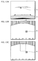
- FIG. 1A is a block diagram of the conventional surroundings monitoring apparatus, and FIG. 1B shows an example of a synthetic image, which are described in Patent Document 2.
- image memories 7-1 to 7-8 temporarily store images captured by the cameras, and a combination of an address counter 13-1, a vertical address look-up table (LUT) 13-2, a horizontal address LUT 13-3, and a memory selector LUT 13-4 generates the image coordinates for the captured image which correspond to each pixel of the synthetic image, in other words, an address in each of the image memories.
- a memory selector 13-5 reads the image in the image memories.
- the surroundings monitoring apparatus including the aforementioned look-up tables can generate images by calculating a correspondence between a captured image and a synthetic image in the coordinates beforehand, storing the results in the look-up tables, and referring to the look-up tables in execution. Therefore, there is an advantage that the calculation load in execution is small.
- the positions of the surrounding objects in the synthetic image are displaced with respect to the synthetic image at the time of creating the look-up tables, and the joining areas of the images captured by the cameras which are in the synthetic image become discontinuous.
- the superimposing is not preferable because the position relationship between the surrounding objects and the vehicle may be misunderstood.
- a camera position at the time of creating a look-up table is referred to as a "reference camera position”
- an image synthesis parameter such as a look-up table generated with respect to the reference camera position
- a reference image synthesis parameter an image which is generated using an image captured in the reference camera position and the reference image synthesis parameter is referred to as a "reference synthetic image”.
- Non-patent Document 1 As a method for correcting the distortions in the synthetic image caused by such position displacement of the camera, a method called the camera calibration method is known which measures an inner parameter, a camera position after installing the camera or the like (for example, refer to Non-patent Document 1).
- the present invention has been conceived in view of the aforementioned circumstances, and aims at providing a surroundings monitoring apparatus and a surroundings monitoring method which can reduce distortions, on a displayed image, which occur due to a position displacement of a camera in the case where the position of the camera is displaced with respect to the reference camera position used for calculating a parameter for synthesizing images, such as a look-up table.
- the surroundings monitoring apparatus is a surroundings monitoring apparatus which generates a surrounding image using an image captured by a camera
- the surroundings monitoring apparatus includes: a position displacement information obtainment unit that obtains position displacement information which is information regarding a displacement in a position of the camera; a coordinate transformation parameter obtainment unit that obtains, based on the position displacement information obtained by the position displacement information obtainment unit, a coordinate transformation parameter for correcting a distortion in the surrounding image caused by the displacement in the position, the coordinate transformation parameter being a set of coefficients for identifying a function for transforming coordinates of a pixel in an image into coordinates at which the distortion has been corrected; an image synthesis parameter obtainment unit that obtains a reference image synthesis parameter which is used for generating the surrounding image using the captured image, the reference image synthesis parameter including information of image coordinates indicating, on the captured image, a pixel position corresponding to each pixel in the surrounding image; a coordinate transformation unit that performs coordinate transformation on the image coordinates included in
- the surroundings monitoring apparatus and the surroundings monitoring method in the present invention even in the case of using a captured image with a position displacement of a camera, it is possible to easily reduce distortions on a surrounding image caused by the position displacement of the camera.
- the surroundings monitoring apparatus is a surroundings monitoring apparatus which generates a surrounding image using an image captured by a camera
- the surroundings monitoring apparatus includes: a position displacement information obtainment unit that obtains position displacement information which is information regarding a displacement in a position of the camera; a coordinate transformation parameter obtainment unit that obtains, based on the position displacement information obtained by the position displacement information obtainment unit, a coordinate transformation parameter for correcting a distortion in the surrounding image caused by the displacement in the position, the coordinate transformation parameter is a set of coefficients for identifying a function for transforming coordinates of a pixel in an image into coordinates at which the distortion has been corrected; an image synthesis parameter obtainment unit that obtains a reference image synthesis parameter which is used for generating the surrounding image using the captured image, the reference image synthesis parameter including information of image coordinates indicating, on the captured image, a pixel position corresponding to each pixel in the surrounding image; a coordinate transformation unit that performs coordinate transformation on the image coordinates included in the reference image synthesis parameter
- the surroundings monitoring apparatus further includes a graphics synthesis unit that superimposes graphics on the surrounding image generated by the image synthesis unit, and that outputs the image superimposed with graphics, wherein the coordinate transformation parameter obtainment unit may obtain the coordinate transformation parameter based on the position displacement information obtained by the position displacement information obtainment unit and the graphics superimposed by the graphics synthesis unit.
- the image synthesis parameter obtainment unit may include: an image synthesis parameter storage unit that stores at least one reference image synthesis parameter beforehand; and an image synthesis parameter selection unit that selects a reference image synthesis parameter from the at least one reference image synthesis parameter.
- the coordinate transformation parameter obtainment unit may obtain the coordinate transformation parameter based on the position displacement information obtained by the position displacement information obtainment unit and the reference image synthesis parameter selected by the image synthesis parameter selection unit.
- the reference image synthesis parameter includes plural pieces of information of image coordinates for a plurality of the captured images, the information being used for generating the surrounding image using a plurality of the images captured by plural cameras;
- the position displacement information obtainment unit obtains plural pieces of the position displacement information which are respective pieces of information regarding displacements in the positions of the plural cameras;
- the coordinate transformation parameter obtainment unit obtains a plurality of the coordinate transformation parameters based on the plural pieces of position displacement information obtained by the position displacement information obtainment unit;
- the coordinate transformation unit performs coordinate transformation on the image coordinates included in the reference image synthesis parameter obtained by the image synthesis parameter obtainment unit, using the plurality of coordinate transformation parameters obtained by the coordinate transformation parameter obtainment unit, and outputs the image coordinates as the transformed image synthesis parameter;
- the image synthesis unit generates the surrounding image by applying the plurality of coordinate transformation parameters to the plurality of captured images, the coordinate transformation parameters being obtained by the coordinate transformation parameter obtainment unit.
- the image synthesis parameter obtainment unit may obtain the reference image synthesis parameter which includes information of the image coordinates out of the area of the captured image.
- the image coordinates obtained by performing coordinate transformation on the image coordinates may be within the area of the captured image.
- the present invention can be realized not only as such a surroundings monitoring apparatus, but also as a surroundings monitoring method having the characteristic units of the aforementioned surroundings monitoring apparatus as steps, and as a program which causes a computer to execute such steps.
- a program which causes a computer to execute such steps.
- such program can be distributed via a recording medium, such as a CD-ROM and via a transmission medium, such as the Internet.
- FIG. 2 is a block diagram showing the configuration of the surroundings monitoring apparatus according to the first embodiment of the present invention.
- the surroundings monitoring apparatus is, for example, an apparatus which is installed in a moving object such as an automobile, and generates a synthetic image (surrounding image) by deforming images captured by cameras.
- the apparatus includes cameras 101, an A/D converter 102, a frame memory 103, an image synthesis unit 104, a graphics synthesis unit 105, a D/A converter 106, a display 107, a position displacement information obtainment unit 108, a moving object state detection unit 109, a coordinate transformation parameter obtainment unit 120, a coordinate transformation unit 112, and an image synthesis parameter obtainment unit 121.
- the cameras 101 capture images of the surroundings of the vehicle and output image sequence.
- the A/D converter 102 digitizes the image sequence which is an analog signal.
- the frame memory 103 temporarily holds the digitized image sequence. Note that at least one of the camera 101, the A/D converter 102 and the frame memory 103 need to be equipped with.
- the frame memory 103 is a frame memory with double buffer configuration which successively reads the image sequence outputted from the cameras 101 while temporarily holding image data having at least one frame.
- the frame memory 103 is configured such that arbitrary pixel data for an image having the held single frame can be read in response to a read request from the image synthesis unit 104.
- the position displacement information obtainment unit 108 receives a position displacement degree of each camera through the user's manipulation of the switch, and outputs the received position displacement degree of each camera as the camera position displacement information.
- the position displacement degree of each camera is received by the user in the present first embodiment, the present invention is not limited to such a case.
- the position displacement degree of each camera may be detected by a sensor and the like, and the detected position displacement degree of each camera may be outputted as the camera position displacement information.
- the moving object state detection unit 109 detects vehicle speed, a shift lever, and a steering angle and outputs them as a moving object state.
- vehicle speed, shift lever, and steering angle are detected in the present first embodiment, the present invention is not limited to such a case.
- the moving object state detection unit 109 has only to output, as the moving object state, detection results from one or more of switches which the user manipulates, such as an ignition key, a shift lever, a blinker and the like, or sensors such as a vehicle speed sensor or a steering angle sensor that detects speed and a moving direction of the vehicle.
- the coordinate transformation parameter obtainment unit 120 includes a coordinate transformation parameter selection unit 110 and a coordinate transformation parameter storage unit 111.
- the coordinate transformation parameter storage unit 111 stores a plurality of coordinate transformation parameters beforehand.
- the coordinate transformation parameter selection unit 110 selects and outputs one of the coordinate transformation parameters stored in the coordinate transformation parameter storage unit 111 according to the camera position displacement information.
- the image synthesis parameter obtainment unit 121 includes an image synthesis parameter selection unit 113 and an image synthesis parameter storage unit 114.
- the image synthesis parameter storage unit 114 stores at least one reference image synthesis parameter and at least one graphics parameter beforehand.
- the image synthesis parameter selection unit 113 selects and outputs, depending on the moving object state, one of the reference image synthesis parameters and one of the graphics parameters which are stored in the image synthesis parameter storage unit 114.
- the coordinate transformation unit 112 performs coordinate transformation on the image coordinates of the captured image included in the reference image synthesis parameter outputted from the image synthesis parameter selection unit 113, using the coordinate transformation parameter outputted from the coordinate transformation parameter selection unit 110, and outputs the image coordinates as a transformed image synthesis parameter.
- the image synthesis unit 104 sequentially reads images from the frame memory 103 depending on the transformed image synthesis parameter outputted from the coordinate transformation unit 112, generates a synthetic image, and outputs the generated image.
- the graphics synthesis unit 105 superimposes, on the synthetic image outputted from the image synthesis unit 104, the graphics corresponding to the graphics parameter outputted from the image synthesis parameter selection unit 113, and outputs it as the synthetic image with the graphics.
- the D/A converter 106 transforms the synthetic image with the graphics to an analog signal.
- the display 107 displays the synthetic image with the graphics which has been transformed into the analog signal.
- FIG. 3 is a diagram showing an installation example in this case.
- a plurality of the cameras 101 in FIG. 2 correspond to a camera 101a to 101c (cameras 1-3) in FIG. 3 , and each camera is installed in the vehicle so as to capture an image of the surroundings of the vehicle.
- the display 107 is installed in a position which can be seen from a driver in the vehicle, and other processing units are installed inside the vehicle. Note that the number of the cameras 101 and the respective installation positions are not limited to the ones in shown in FIG. 3 , and the installation positions of other processing units are not limited in the same manner.
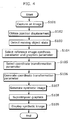
- FIG. 4 is a flowchart showing a flow of the operation of the surroundings monitoring apparatus.
- the cameras 101 capture images of the surroundings of the vehicle, and output a video signal corresponding to each image, the A/D converter 102 digitizes the video signal and outputs the digitized image, and the frame memory 103 temporarily stores the digitized image (Step S101). Storing and updating images in the frame memory 103 is successively performed in synchronization with the video signals outputted from the cameras 101.
- FIGS. 5A to 5C are diagrams showing examples of images captured by the cameras 101a to 101c in the imaging situation of FIG. 3 , where FIG. 5A shows an image captured at the rear of the vehicle by the camera 101a; FIG. 5B shows an image captured at the left side of the vehicle by the camera 101b; and FIG. 5C shows an image captured at the right side of the vehicle by the camera 101c.
- the images shown in FIGS. 5A to 5C are stored in digitized form.
- the position displacement information obtainment unit 108 obtains the position displacement of each camera, and outputs it as the camera position displacement information (Step S102).
- the specific example of the camera position displacement is described hereinafter.
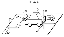
- FIG. 6 is a diagram showing the arrangement of a camera coordinate system (Xe, Ye, Ze), a vehicle coordinate system (Xc, Yc, Zc), and a world coordinate system (Xw, Yw, Zw).
- a camera coordinate system Xe, Ye, Ze
- a vehicle coordinate system Xc, Yc, Zc
- a world coordinate system Xw, Yw, Zw.
- the former position is referred to as a vehicle location
- the latter position is referred to as an installation position of a camera.
- a camera position displacement is a difference from a reference position in the case where a vehicle location and an installation position of a camera at the time of generating a reference image synthesis parameter are the reference positions, and the camera position displacement occurs due to the displacement in the vehicle location and the displacement in the installation position of the camera.
- the camera installation position displacement Ee can be expressed by six parameters of three-dimensional translation and rotation (ex, ey, ez, ewx, ewy, ewz), and the k-th camera installation position displacement Eek can be expressed as (exk, eyk, ezk, ewxk, ewyk, ewzk).
- the vehicle is assumed to be free to move in an X-Z plane (road surface) with respect to the world coordinate system, and to rotate around the Y-axis, and the location displacement Ec of the vehicle can be expressed by three parameters (eyc, ewxc, ewzc).
- the position displacement Ek for the k-number of cameras are collectively referred to as camera position displacement information.
- the camera position displacement E is expressed by a single parameter (ewy), which is displacement of the rotation around the Y-axis in the camera coordinate system with respect to the vehicle coordinate system.
- the position displacement information obtainment unit 108 receives a value of a position displacement of each camera through the user's manipulation of the switch and outputs the inputted position displacement Ek for the k-number of cameras as the camera position displacement information.
- the camera's position displacement degree ewyk 0 is outputted.
- the moving object state detection unit 109 detects and outputs the vehicle speed, shift lever, and steering angle as the moving object state (Step S103).
- the moving object state detection unit 109 outputs, as the moving object state, the state that "the vehicle is stopped, the shift lever is placed in reverse (hereinafter referred to as "R"), and the steering is in a neutral position".
- the image synthesis parameter selection unit 113 selects and outputs, depending on the moving object state outputted from the moving object state detection unit 109, one of the reference image synthesis parameters and one of the graphics parameters which are stored in the image synthesis parameter storage unit 114 (Step S104).
- Each parameter stored in the image synthesis parameter storage unit 114 and an operation of the image synthesis parameter selection unit 113 are described in detail hereinafter.
- FIG. 7 (a), (b), and (c) is a diagram for describing reference image synthesis parameters stored in the image synthesis parameter storage unit 114, where FIG. 7 (a) shows an example of a captured image, FIG. 7 (b) shows an example of a synthetic image, and FIG. 7 (c) shows an example of a reference image synthesis parameter in the case of generating the synthetic image from the captured images.
- the reference image synthesis parameter in FIG. 7 (c) can be expressed as a two-dimensional array corresponding to each pixel of the synthetic image on a one-to-one basis.
- Each element of the two-dimensional array is composed of the camera number of the captured image and pixel coordinates (an X coordinate and a Y coordinate in the present embodiment) which correspond to each pixel in the synthetic image.
- FIGS. 8A to 8C are diagrams showing an example of a plurality of synthetic images generated by using a plurality of the reference image synthesis parameters. Illustrated here is the synthetic image generated by using each reference image synthesis parameter in the case where the images in FIGS. 5A to 5C are captured in the imaging situation of FIG. 3 . For the same captured image, by using a reference image synthesis parameter which differs in the camera number and the captured image coordinate values, a synthetic image with a different composition can be generated.
- FIG. 8A is an example of a synthetic image generated by a reference image synthesis parameter 1, and the reference image synthesis parameter 1 indicates a correspondence between an image captured by the camera 101a and a synthetic image with a composition seen from above the vehicle.
- FIG. 8B is an example of a synthetic image generated by a reference image synthesis parameter 2
- the reference image synthesis parameter 2 indicates a correspondence with a synthetic image having the same composition as the image captured by the camera 101a.
- FIG. 8C is an example of a synthetic image generated with a reference image synthesis parameter 3, and the reference image synthesis parameter 3 indicates a correspondence between images captured by the camera 101a to 101c and a synthetic image with a composition in which an large area covering from the side to the rear of the vehicle is seen from above the vehicle.
- the method of creating a reference image synthesis parameter is described in detail in the aforementioned Patent Document 3, the detailed description is omitted here.
- FIGS. 9A to 9E are diagrams showing an example of graphics generated using a graphics parameter. It is assumed that the graphics parameter is stored as an image file having the same size as the synthetic image.
- the graphics parameter 1 that generates the graphics shown in FIG. 9A corresponds to the reference image synthesis parameter 1
- graphics parameters 2-1 to 2-3 that generate the graphics shown in FIGS. 9B to 9D correspond to the reference image synthesis parameter 2
- the graphics parameter 3 that generates the graphics shown in FIG. 9E corresponds to the reference image synthesis parameter 3.
- each dashed line rendered in FIGS. 9A to 9E is graphics indicating a particular and predetermined distance with respect to the reference vehicle. For example, each dashed line rendered in FIGS.
- the graphics generated by the graphics parameters include reference information about a distance to the vehicle and a position with respect to the vehicle. Such graphics can be generated beforehand by associating a position on a synthetic image with a position on a road plane or a position on the captured image when the aforementioned reference image synthesis parameter is created.
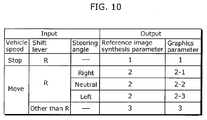
- FIG.10 is a diagram showing an example of a method for selecting a reference image synthesis parameter in the image synthesis parameter selection unit 113.
- the image synthesis parameter selection unit 113 respectively selects a reference image synthesis parameter and a graphics parameter depending on a combination of the vehicle speed, shift lever, and steering angle which are inputted as the moving object state as shown in FIG. 10 .
- the shift lever is placed in R, and the steering is in a neutral position
- the reference image synthesis parameter 2 is selected.
- the image synthesis parameter selection unit 113 selects and outputs the reference image synthesis parameter 1 and graphics parameter 1.
- the coordinate transformation parameter selection unit 110 selects and outputs, according to the camera position displacement information, one of the coordinate transformation parameters stored in the coordinate transformation parameter storage unit 111 (Step S105).
- the coordinate transformation unit 112 performs coordinate transformation on the image coordinates of the captured image which is included in the reference image synthesis parameter outputted from the image synthesis parameter selection unit 113 using the coordinate transformation parameter outputted from the coordinate transformation parameter selection unit 110 and outputs the image coordinates as a transformed image synthesis parameter (Step S106).
- the coordinate transformation performed in the coordinate transformation unit 112 is projective transformation
- the coordinate transformation parameter stored in the coordinate transformation parameter storage unit 111 is a set of coefficients of projective transformation for every camera.
- Equation 1 eight coefficients (a, b, c, d, e, f, g, h) of projective transformation are referred to as coordinate transformation parameters.
- the coordinates (xi, yi) are image coordinates of the captured image included in the reference image synthesis parameter, and the coordinates (xi', yi') are image coordinates of the captured image included in the transformed image synthesis parameter.
- the coordinate transformation parameters stored in the coordinate transformation parameter storage unit 111 are a plurality of coordinate transformation parameters P which correspond to the values of the camera position displacement E and the camera number k.
- the coordinate transformation parameter P is expressed as P (E, k) as it depends upon the camera position displacement E and camera number k. It is assumed that in the present embodiment, the camera position displacement E is limited to the camera installation position displacement ewy, that the value can take 21 levels of values per degree in the range between -10 to +10 degrees, and that 21 coordinate transformation parameters corresponding to each of such degree angle are calculated and stored beforehand for each camera number.
- Equation 1 the fact that a relationship between the corresponding points of image coordinates can be expressed by Equation 1 in the case where the camera position displacement E is limited to rotation, or in the case where a photographic subject in the image is present on one plane is widely known as described in "Gazo Rikai (Image understanding)” (Author: Kenichi Kanatani, Morikita Shuppan Co., Ltd.) and the like. Therefore, in the case where a road plane occupies a large percentage of the captured image, for example, it is possible to transform the image to an image with no camera position displacement on the road by performing projective transformation on the image with the camera position displacement.
- the coordinate transformation unit 112 inputs a reference image synthesis parameter and a coordinate transformation parameter for every camera, and calculates (xi', yi') by performing coordinate transformation of Equation 1, using the coordinate transformation parameter corresponding to the camera number, on the image coordinates (xi, yi) for the camera number and the captured image, which are respective elements of the reference image synthesis parameter. Then, the coordinate transformation unit 112 replaces respective image coordinates for the captured image in the reference image synthesis parameter (xi, yi) with the calculated image coordinates (xi', yi'), and outputs the transformed image synthesis parameter.
- the image synthesis unit 104 sequentially reads the captured images corresponding to each element of the transformed image synthesis parameter, using the transformed image synthesis parameters generated by the coordinate transformation selection unit 112, and outputs them as a synthetic image (Step S107).
- the synthetic image in FIG. 8A is outputted in the case where the captured images are, for example, those shown in FIGS. 5A to 5C .
- the graphics synthesis unit 105 superimposes, on the synthetic image generated in the image synthesis unit 104, the graphics corresponding to the graphics parameter selected in the image synthesis parameter selection unit 113 (Step S108).
- the graphics parameter 1 is selected by the image synthesis parameter selection unit 113
- the graphics in FIG. 9A is superposed on the synthetic image, and the synthetic image with the graphics is outputted.
- the D/A converter 106 transforms the synthetic display image outputted from the graphics synthesis unit 105 into a video signal and outputs the video signal, and the display 107 displays the video signal (Step S109).
- the synthetic image with graphics in an initial state is generated and displayed on the display 107.
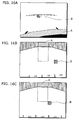
- FIGS. 13A to 13C are diagrams showing an example of the images to be generated by the operation in an initial state.
- FIG. 13A is an image captured by the camera 101a
- FIG. 13B is an example of a synthetic image outputted from the image synthesis unit 104
- FIG. 13C is an example of a synthetic image with the graphics outputted from the graphics synthesis unit 105 and displayed on the display 107.
- the driver monitors the synthetic image with graphics in FIG. 13C
- a position relationship between a dashed line and an obstacle can be easily understood, as the dashed line used as a reference for the position is superimposed on the image.
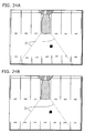
- FIG. 14 is a diagram showing an example of a captured image when the position of the camera 101a is displaced from the reference position.
- FIG. 14 (a) is a captured image without displacement
- FIG. 14 (b) is an example of a captured image in the case where a camera installation position is displaced by five degrees by rotation to the right direction with respect to the vertical axis.
- FIGS. 15A and 15B are diagrams showing an example of synthetic images with graphics generated by the aforementioned operation in the initial state in the case where FIG. 14 is used as the captured image.
- FIG. 15A is a synthetic image with graphics in the case where FIG. 14 (a) is used as the captured image
- FIG. 15B is a synthetic image with graphics in the case where FIG. 14 (b) is used as the captured image.
- the processing for correcting the position to be described hereinafter aims at generating an image as same as FIG. 15A or an image closer to FIG. 15A , even in the case where the captured image in FIG. 14(b) having the camera position displacement is inputted.
- FIG. 16A is an example of a captured image in the case where a camera installation position is displaced by five degrees by rotation to the right direction with respect to the vertical axis.
- FIG. 16B is a synthetic image with graphics in the case of performing no coordinate transformation
- FIG. 16C is a synthetic image with graphics in the case where coordinate transformation has been performed.
- FIG. 16A and FIG. 14(b) , and FIG. 16B and FIG. 15B are respectively the same images).
- an arbitrary camera position displacement Ek is inputted, and the position displacement information obtainment unit 108 receives the camera position displacement Ek.
- the user sequentially inputs Ek as the camera installation position displacement ewyk per degree in the range between -10 to +10 degrees, and stops manipulating the switch when the surrounding condition best matches the synthetic image. Then, in the case where the camera position displacement set by the user is equal to the actual camera position displacement, the image as shown in FIG. 16C is generated.
- a synthetic image is generated, using the transformed image synthesis parameter obtained as a result of performing coordinate transformation depending on the camera position displacement in response to the user's designation. Therefore, even in the case where the captured image with the camera position displacement is used, there is an effect that the displacement between a photographic subject of the synthetic image and the graphics can be reduced.
- the present first embodiment produces an effect that recalculation of a reference image synthesis parameter, a transformed image synthesis parameter, a graphics parameter and the like is not required and the calculation load in execution is small even when a camera position displacement occurs.
- the user inputs the camera position displacement E while monitoring the image as shown in FIGS. 16A to 16C under the scene of FIG. 3 .
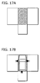
- FIG. 18A is an example of an image captured by the camera 1 under the surrounding condition of FIG.
- FIG. 18B is an example in the case where the same graphics as the graphics on the road in FIGS. 17A and 17B are generated by the graphics synthesis unit 105, and in the case where there is no camera position displacement, the generated graphics (shown by a dashed line) corresponds to the graphics on the road in the captured image.
- the graphics on the road is displaced from the position of the generated graphics as shown in FIG. 18C .
- the graphic synthesis unit 105 may selectively perform, according to the manipulation by the user, processing of recording the synthetic image inputted from the image synthesis unit 104 or processing of superimposing the recorded synthetic image on the synthetic image inputted from the image synthesis unit 104 and outputting the resulting image, in addition to the aforementioned processing. Then, the user records, for example, a synthetic image shown in FIG.
- the camera position displacement E is composed of only ewy, which is one of the parameters indicating a camera installation position displacement, and the parameter is inputted by the user.
- ewy which is one of the parameters indicating a camera installation position displacement
- the parameter is inputted by the user.
- a combination of all or any of the six parameters (ex, ey, ez, ewx, ewy, ewz) indicating the camera installation position displacement Ee and three parameters (eyc, ewxc, ewzc) indicating the location displacement Ec of the vehicle may be used.
- the location displacement Ec of the vehicle may be obtained by a detection unit which is a combination of an acceleration sensor which detects a location of the vehicle, an angular acceleration sensor and the like.
- the user designates the optimal camera position displacement E by inputting the arbitrary camera position displacement E into the position displacement information obtainment unit 108, while monitoring the synthetic image.
- the first embodiment is not limited to this method. For example, by performing the camera calibration, the camera position displacement may be calculated and the calculated value may be inputted.
- the coordinate transformation parameter obtainment unit 120 includes the coordinate transformation parameter selection unit 110 and coordinate transformation parameter storage unit 111, and the coordinate transformation parameter selection unit 110 selects one of the coordinate transformation parameters stored in the coordinate transformation parameter storage unit 111 according to the camera position displacement information.
- the coordinate transformation parameter obtainment unit 120 may generate a coordinate transformation parameter based on the camera position displacement information.
- the coordinate transformation unit 112 uses projective transformation.
- the coordinate transformation method is not limited to the projective transformation. Any coordinate transformation may be used, as long as such transformation has an effect of correcting the camera position displacement.
- FIG. 20 is a block diagram showing the configuration of the surroundings monitoring apparatus according to the second embodiment of the present invention.
- the present embodiment differs from the first embodiment in the details of a coordinate transformation parameter P stored in the coordinate transformation parameter storage unit 212 and the operations of the coordinate transformation parameter selection unit 211 and coordinate transformation unit 201.
- the coordinate transformation unit 201 of the present second embodiment performs coordinate transformation on the image coordinates of the captured image included in the reference image synthesis parameter outputted from the image synthesis parameter selection unit 221 by using the coordinate transformation parameter outputted from the coordinate transformation parameter selection unit 212 according to the affine transformation using Equation 2 indicated below, and outputs the resulting image coordinates as a transformed image synthesis parameter.
- x i ⁇ ax i + by i + c
- y i ⁇ dx i + ey i + f
- the coordinate transformation parameter is composed of six coefficients (a, b, c, d, e, f) in Equation 2.
- the coordinate transformation parameter stored in the coordinate transformation parameter storage unit 212 is a coordinate transformation parameter P (E, q, r, k) which is calculated beforehand depending on the camera position displacement E, reference image synthesis parameter number q, graphics parameter number r, and camera number k.
- the coordinate transformation parameter selection unit 211 selects and outputs the coordinate transformation parameter P (E, q, r, k) which corresponds to the position displacement E for each camera which is included in the camera position displacement information, camera number k, the reference image synthesis parameter number p selected in the image synthesis parameter selection unit 221 and graphics parameter number r.
- the reference image synthesis parameter number p and the graphics parameter number r are obtained with the selection method shown in FIG. 10 based on the moving object state inputted from the moving object state detection unit 109.
- the coordinate transformation parameter P (E, q, r, k) is described hereinafter.
- the coordinate transformation parameter is calculated from a plurality of coordinates which indicate corresponding points between a captured image without a position displacement and a captured image with a certain position displacement E.
- the different point from the first embodiment is to calculate a coordinate transformation parameter, using a different corresponding point depending on the camera number k, the reference image synthesis parameter number p and the graphics parameter number r.
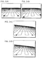
- the "circle marks” and “x marks” in FIG. 21A and 21B respectively indicate a set of four corresponding points, and those points are provided as points on the captured image which is on the dashed line of the image generated by the graphics parameter 2-2 which generates graphics shown in FIG. 9C and the graphics parameter 2-1 which generates graphics shown in FIG. 9B . Then, the coordinate transformation parameter is calculated for each set of the corresponding points.
- a corresponding point of the "x mark” and a corresponding point of the "circle mark” are points on the captured image respectively corresponding to the graphics parameter 2-2 and graphics parameter 2-1.
- the graphics parameter 2-1 and graphics parameter 2-2 are selected by the selection method in FIG.
- the coordinate transformation parameter calculated using a corresponding point of the "x mark” is a coordinate transformation parameter P (E, 2, 2-2,1) in the case of "camera position displacement E, reference image synthesis parameter 2, graphics parameter 2-2, camera 1"
- the coordinate transformation parameter calculated using a corresponding point of the "circle mark” is a coordinate transformation parameter P (E, 2, 2-1, 1) in the case of "camera position displacement E, reference image synthesis parameter 2, graphics parameter 2-1, camera 1".
- FIGS. 21C and 21D are examples of synthetic images generated by performing coordinate transformation using the captured image with the camera position displacement in FIG. 21B and using the aforementioned two coordinate transformation parameters.
- the affine transformation can completely correct the displacement in a captured image as long as the camera position displacement is limited to rotation of the camera with respect to the Z axis. However, the camera position displacement caused by other types of rotation and translation can not be completely corrected.
- the affect of this position displacement is expected to be minimal in the positions of the corresponding points used for calculating the aforementioned coordinate transformation parameters.
- the synthetic images of FIGS. 21C and 21D are synthetic images with less position displacements caused by the camera position displacement.
- Example images are shown which are generated by the operations of the aforementioned coordinate transformation parameter selection unit 211, coordinate transformation unit 201 and each processing unit using the coordinate transformation parameter generated by the aforementioned method.
- FIG. 22A is a synthetic image with graphics in the case where there is no camera position displacement
- FIG. 22B is a synthetic image with graphics in the case where a camera position displacement is present.
- FIG. 22A is a synthetic image with graphics in the case where there is no camera position displacement
- FIG. 22B is a synthetic image with graphics in the case where a camera position displacement is present.
- 23A is an example of a synthetic image with graphics in the case where a preferable camera position displacement E is inputted through the manipulation of the user as in the first embodiment, in other words, a synthetic image with graphics obtained by performing the coordinate transformation using the aforementioned coordinate transformation parameter P (E,2,2-2,1). Whereas there is a relationship of a position displacement between a photographic subject (an obstacle in particular) and graphics in FIG. 22B , the displacement is reduced in FIG. 23A .
- the graphics parameter 2 is used in the graphics synthesis unit 105, and the coordinate transformation parameter P (E,2,2-1,1) is used in the coordinate transformation unit 112 so as to generate the synthetic image with graphics in FIG. 23B .
- the synthetic images are generated in which the position displacement after the coordinate transformation is minimal in the position of the dashed line in the image.
- the position displacement is less in parts where position relationship is important, such as a relationship in the synthetic image between an obstacle and a dashed line or graphics of the vehicle which is used as a reference position, it is possible to understand more accurate position relationship.
- the coordinate transformation parameter obtainment unit 210 performs coordinate transformation on the reference image synthesis parameter suitable for the graphics superimposed on the synthetic image by generating the coordinate transformation parameter suitable for the graphics superimposed in the graphics synthesis unit 105. Therefore, there is an effect that an image with a less displacement between the graphics and synthetic image can be displayed.
- any combination may be used as long as the coordinate transformation parameter is composed of a combination of a camera position displacement, a reference image synthesis parameter, a graphics parameter, and camera number, and a different coordinate transformation parameter may be used depending on the reference image synthesis parameter.
- the coordinate transformation parameter is composed of a combination of a camera position displacement, a reference image synthesis parameter, a graphics parameter, and camera number
- a different coordinate transformation parameter may be used depending on the reference image synthesis parameter.
- the areas of captured images which are used to generate each of the synthetic images are different between the reference synthesis image parameter 1 which generates the synthetic image shown in FIG. 8A and the reference image synthesis parameter 2 which generates the synthetic image shown in FIG. 8B , even when the synthetic images are generated by the images captured by the same camera 1. Therefore, when obtaining a coordinate transformation parameter, for example, by providing the corresponding points suitable for the area of the captured image, there is an effect that it is possible to generate a synthetic image with a less position displacement suitable for the composition of the reference image synthesis parameter.
- the coordinate transformation unit 201 performs coordinate transformation using the affine transformation in the present second embodiment
- the coordinate transformation method is not limited to the affine transformation, and any transformation may be used as long as the coordinate transformation is effective at correcting the camera position displacement.
- the position displacement remains in the synthetic image in which the coordinates has been transformed.
- the position displacement on the synthetic image is reduced in the position of the corresponding points used for calculating the coordinate transformation parameter, as in the case of the present second embodiment, it is possible to generate a synthetic image which is less affected by a position displacement by using the coordinate transformation parameter corresponding to the graphics.
- the configuration and operation are the same as the second embodiment, and different points from the second embodiment are that the cameras 101 are cameras which output images captured with distorted lenses, and that the cameras 101 having the distorted lenses are used, in each of which the position error within the range of the predetermined camera position displacement and the range of the reference image synthesis parameter is minimal after performing coordinate transformation.
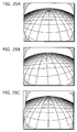
- FIGS. 25A to 25C are diagrams showing examples of the captured images using the distorted lenses, and the synthetic images generated according to the same operation as the second embodiment.
- FIG. 25A is an example of a captured image in the case where the camera 101 outputs the image using the distorted lens
- FIG. 25B is an example of a captured image in the case where the camera position is displaced.
- a coordinate transformation parameter is obtained beforehand from a captured image without a camera position displacement and images with position displacements of plural cameras which can be obtained in the possible range of the camera position displacement E
- the synthetic image as shown in FIG. 25C is generated by performing coordinate transformation using the obtained coordinate transformation parameter.
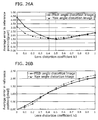
- FIGS. 26A and 26B are diagrams, each of them showing a relationship between the average error and the lens distortion k1 in the case where the coordinate transformation is performed on the image captured using the distorted lens, where FIG. 26A shows the case of using affine transformation, and FIG. 26B shows the case of using projective transformation.
- the reference image synthesis parameter is composed of image coordinate values of the captured image corresponding to the image coordinates of the synthetic image
- image coordinate values out of the area of the captured image may be designated. Even in the case where the image coordinate values out of the area of the captured image are included in the reference image synthesis parameter, there is an effect that the transformed image synthesis parameter on which coordinate transformation is performed in the coordinate transformation unit may be replaced with a coordinate value within the area of the captured image, and the area of the image displayed as a synthetic image can be expanded.
- the coordinate transformation unit may select and output, as a transformed image synthesis parameter, one of the sets of the image coordinates within the area of the captured image after performing coordinate transformation.
- the coordinate transformation unit may select and output, as a transformed image synthesis parameter, one of the sets of the image coordinates within the area of the captured image after performing coordinate transformation.
- the moving object state detection unit 108 and the image synthesis parameter selection unit 113 are assumed to use the vehicle speed, shift lever and steering angle as the moving object state, kinds of moving object states and selection methods of a parameter are not limited to them. Any information may be used as long as the moving object state is related to the composition of the synthetic image. For example, road situations may be obtained from obtained position information of the vehicle which has been obtained by a Global Positioning System (GPS) device, and the vehicle location may be estimated based on the road situations. Then, depending on this vehicle location, the reference image synthesis parameter and coordinate transformation parameter may be selected.
- GPS Global Positioning System
- the image synthesis parameter selection unit 113 selects a reference image synthesis parameter according to the selection method in FIG. 10
- the selection methods in the present invention are not limited to the aforementioned selection method, and any selection method may be used.
- the vehicle in which a plurality of cameras and the surroundings monitoring apparatus are installed is described as a four-wheel vehicle, the vehicle type is not limited, and moving objects such as a two-wheel vehicle, a three-wheel vehicle and a robot may also be used.
- a place where a plurality of cameras and the surroundings monitoring apparatus are installed is not limited to the moving objects, and such cameras and apparatus may be fixed and installed, for example, in a station, a building, or the like.
- a plurality of cameras and the surroundings monitoring apparatus need not to be installed in the same moving object or place, and the cameras and the surroundings monitoring apparatus may be installed separately in a different place.
- each processing unit is implemented by individual hardware, each processing unit may be included in a single IC and the like, or it may be implemented by software executed in a computer provided with an input and output unit for images as shown in FIG. 27 (CPU 1004, ROM 1005, RAM 1006, and the like), and thereby the same effect as the embodiments of the present invention can be obtained.
- the surroundings monitoring apparatus is capable of correcting, in a displayed image, distortions caused by a camera position displacement, and is useful as a surroundings monitoring apparatus which can assist operations of moving objects, such as driving a vehicle and remotely controlling a robot.
- a surroundings monitoring apparatus which generates and displays a synthetic image as if it were captured from a virtual viewpoint, using images captured by a plurality of cameras.
- the present invention can be applied to a monitoring apparatus aimed at security and an image synthesis device aimed at creating video.
Landscapes
- Engineering & Computer Science (AREA)
- Multimedia (AREA)
- Physics & Mathematics (AREA)
- General Physics & Mathematics (AREA)
- Signal Processing (AREA)
- Mechanical Engineering (AREA)
- Closed-Circuit Television Systems (AREA)
- Image Processing (AREA)
Claims (20)
- Umgebungsüberwachungsvorrichtung, die ein Umgebungsbild unter Anwendung eines mit einer Kamera erfassten Bildes erzeugt, wobei die Umgebungsüberwachungsvorrichtung Folgendes aufweist:eine Positionsverschiebungsinformation-Ermittlungseinheit (108), die operabel ist zum Erhalten von Positionsverschiebungsinformation, das ist Information bezüglich einer Verschiebung in eine Position in der Kamera;eine Koordinatentransformationsparameter-Ermittlungseinheit (120), die operabel ist, um, auf Basis der von der Positionsverschiebungsinformation-Ermittlungseinheit erhaltenen Positionsverschiebungsinformation, einen Koordinatentransformationsparameter zum Korrigieren einer durch die Verschiebung in der Position verursachte Verzerrung im Umgebungsbild zu erhalten, wobei es sich bei dem Koordinatentransformationsparameter um einen Satz von Koeffizienten zum Identifizieren einer Funktion zum Transformieren von Koordinaten eines Pixels in einem Bild in Koordinaten, bei denen die Verzerrung korrigiert worden ist, handelt;eine Bildsyntheseparameter-Ermittlungseinheit (121), die operabel ist um, einen Referenzbild-Syntheseparameter zu erhalten, der zum Erzeugen des Umgebungsbilds unter Anwenden des erfassten Bildes benutzt wird, wobei der Referenzbild-Syntheseparameter Information über die Bildkoordinaten enthält, die, auf dem erfassten Bild, eine Pixelposition angibt, die jedem Pixel im Umgebungsbild entspricht;eine Koordinaten-Transformationseinheit (112), die unter Anwenden des von der Koordinatentransformationsparameter-Ermittlungseinheit erhaltenen Koordinatentransformationsparameters, operabel ist zum Ausführen einer Koordinatentransformation an den Bildkoordinaten, die in dem Referenzbild-Syntheseparameter enthalten sind, der durch die Bildsyntheseparameter-Ermittlungseinheit erhalten worden ist, und zum Ausgeben der Bildkoordinaten als einen transformierten Bildsyntheseparameter; undeine Bildsyntheseeinheit (104), die operabel ist zum Erzeugen des Umgebungsbilds durch Anwenden der transformierten Bildsyntheseparameter auf das erfasste Bild und zur Ausgabe des erzeugten Umgebungsbilds.
- Umgebungsüberwachungsvorrichtung nach Anspruch 1, wobei die Koordinatentransformationsparameter-Ermittlungseinheit Folgendes aufweist:eine Koordinatentransformationsparameter- Speichereinheit zum vorherigen Speichern von mindestens einem Koordinatentransformationsparameter; undeine Koordinatentransformationsparameter-Auswähleinheit zum Auswählen eines Koordinatentransformationsparameters unter dem mindestens einen Koordinatentransformationsparameter auf Basis der von der Positionsverschiebungsinformation-Ermittlungseinheit erhaltenen Positionsverschiebungsinformation.
- Umgebungsüberwachungsvorrichtung nach Anspruch 1,
wobei die Koordinatentransformationsparameter-Ermittlungseinheit operabel ist zum Erzeugen des Koordinatentransformationsparameters auf Basis der von der Positionsverschiebungsinformation-Ermittlungseinheit erhaltenen Positionsverschiebungsinformation. - Umgebungsüberwachungsvorrichtung nach Anspruch 1, ferner aufweisendeine Grafiksyntheseeinheit, die operabel ist zum Überlagern von Grafik auf dem Umgebungsbild durch die Bildsyntheseeinheit und zur Ausgabe des Bildes mit überlagerter Grafik,wobei die Koordinatentransformationsparameter-Ermittlungseinheit operabel ist zum Erhalten des Koordinatentransformationsparameters auf Basis der von der Positionsverschiebungsinformation-Ermittlungseinheit erhaltenen Positionsverschiebungsinformation und der von der Grafiksyntheseeinheit überlagerten Grafik.
- Umgebungsüberwachungsvorrichtung nach Anspruch 4,
wobei die Koordinatentransformationsparameter-Ermittlungseinheit operabel ist zum Erhalten eines Koordinatentransformationsparameters, in dem ein Positionsfehler des Umgebungsbildes nach der Koordinatentransformation in einer im Voraus bestimmten Position der von der Grafiksyntheseeinheit überlagerten Grafik minimal ist. - Umgebungsüberwachungsvorrichtung nach Anspruch 1,
wobei die Bildsyntheseparameter-Ermittlungseinheit Folgendes aufweist:eine Bildsyntheseparameter-Speichereinheit, die operabel zum vorherigen Speichern des mindestens einen Referenz-Bildsyntheseparameters; undeine Bildsyntheseparameter-Auswähleinheit, die operabel zum Auswählen eines Referenz-Bildsyntheseparameters von dem mindestens einen Referenz-Bildsyntheseparameter ist. - Umgebungsüberwachungsvorrichtung nach Anspruch 6, ferner aufweisendeine Zustandserkennungseinheit, die operabel ist zum Erkennen eines Zustands eines sich bewegenden Gegenstands einschließlich eines Standorts des sich bewegenden Gegenstands, der mit der Umgebungsüberwachungsvorrichtung ausgerüstet ist,wobei die Bildsyntheseparameter-Auswähleinheit operabel zum Auswählen eines der Referenz-Bildsyntheseparameter auf Basis des von der Zustandserkennungseinheit erkannten sich bewegenden Gegenstands ist.
- Umgebungsüberwachungsvorrichtung nach Anspruch 6,
wobei die Koordinatentransformationsparameter-Ermittlungseinheit operabel ist zum Erhalten des Koordinatentransformationsparameters auf Basis der von der Positionsverschiebungsinformation-Ermittlungseinheit erhaltenen Positionsverschiebungsinformation und des von der Bildsyntheseparameter-Auswähleinheit ausgewählten Bildsyntheseparameters. - Umgebungsüberwachungsvorrichtung nach Anspruch 1, wobei der Referenz-Bildsyntheseparameter Information über die Bildkoordinaten für einen Teil des erfassten Bildes entsprechend dem Umgebungsbild umfasst, und
die Koordinatentransformationsparameter-Ermittlungseinheit operabel ist zum Erhalten eines Koordinatentransformationsparameters, in dem ein Positionsfehler des Umgebungsbilds nach der Koordinatentransformation in einer im Voraus bestimmten Position für den Teil des erfassten Bilds minimal ist. - Umgebungsüberwachungsvorrichtung nach Anspruch 1,
wobei der Referenz-Bildsyntheseparameter mehrere Informationsstücke von Bildkoordinaten für mehrere erfasste Bilder aufweist, die Information unter Anwenden mehrerer der von mehreren Kameras erfasster Bilder zum Erzeugen des Umgebungsbilds benutzt wird,
wobei die Positionsverschiebungsinformation-Ermittlungseinheit operabel ist zum Erhalten mehrerer Informationsstücke der Positionsverschiebungsinformation, die jeweiligen Informationsstücke bezüglich Verschiebungen bei Positionen der mehreren Kameras sind,
wobei die Koordinatentransformationsparameter-Ermittlungseinheit operabel ist zum Erhalten mehrerer Koordinatentransformationsparameter auf Basis der mehreren von der Positionsverschiebungsinformation-Ermittlungseinheit erhaltenen Stücke von Positionsverschiebungsinformation,
wobei die Koordinaten-Transformationseinheit operabel ist zum Ausführen von Koordinatentransformation an dem durch die Bildsyntheseparameter-Ermittlungseinheit erhaltenen Referenz-Bildsyntheseparameter unter Anwendung der mehreren durch die Koordinatentransformationsparameter-Ermittlungseinheit erhaltenen Koordinatentransformationsparameter und zum Ausgeben der Bildkoordinaten als den transformierten Bildsyntheseparameter, und
wobei die Bildsyntheseeinheit operabel ist zum Erzeugen des Umgebungsbilds durch Anwenden der mehreren Koordinatentransformationsparameter auf die mehreren erfassten Bilder, wobei die Koordinatentransformationsparameter von der Koordinatentransformationsparameter-Ermittlungseinheit erhalten werden. - Umgebungsüberwachungsvorrichtung nach Anspruch 10,
wobei der Referenz-Bildsyntheseparameter, für jedes Pixel des Umgebungsbilds, Information umfasst, die ein erfasstes Bild unter mehreren erfassten Bildern und Information über Bildkoordinaten, die eine Pixelposition auf dem erfassten Bild angeben, identifiziert. - Umgebungsüberwachungsvorrichtung nach Anspruch 10,
wobei die Koordinatentransformationsparameter-Ermittlungseinheit operabel ist zum Erhalten eines Koordinatentransformationsparameters, in dem ein Positionsfehler des Umgebungsbilds nach der Koordinatentransformation in einer Grenzposition für mehrere der erfassten Bilder minimal ist, wobei die Grenzposition im Referenz-Bildsyntheseparameter enthalten ist. - Umgebungsüberwachungsvorrichtung nach Anspruch 1,
wobei die Bildsyntheseparameter-Ermittlungseinheit operabel ist zum Erhalten des Referenz-Bildsyntheseparameters, der Information über die Bildkoordinaten außerhalb des Bereichs des erfassten Bildes umfasst. - Umgebungsüberwachungsvorrichtung nach Anspruch 1,
wobei die Bildsyntheseparameter-Ermittlungseinheit operabel ist zum Erhalten des Referenz-Bildsyntheseparameters, der mehrere Informationsstücke der Bildkoordinaten aufweist, die, je Pixel im Umgebungsbild, Positionen von zwei oder mehr Pixeln angeben, die sich auf dem erfassten Bild befinden, und
wobei die Koordinaten-Transformationseinheit operabel ist zum Auswählen eines Pixels nach Ausführen der Koordinatentransformation durch Anwenden des durch die Koordinatentransformationsparameter-Ermittlungseinheit erhaltenen Koordinatentransformationsparameters auf die in dem durch die Bildsyntheseparameter-Ermittlungseinheit erhaltenen Bildsyntheseparameter enthaltenen Bildkoordinaten und Ausgeben der Bildkoordinaten als den transformierten Bildsyntheseparameter. - Umgebungsüberwachungsvorrichtung nach Anspruch 1,
wobei das erfasste Bild ein Linsenverzerrung umfassendes Bild ist, und
wobei die Bildsyntheseeinheit operabel ist zum Erzeugen des Umgebungsbilds unter Anwenden des erfassten einen Linsenverzerrungsparameter aufweisenden Bildes, in dem ein Fehler minimal in dem Umgebungsbild ist, das von einem oder mehreren der im Voraus bestimmten Referenz-Bildsyntheseparameter und einem oder mehreren der im Voraus bestimmten Koordinatentransformationsparameter erzeugt worden ist. - Umgebungsüberwachungsvorrichtung nach Anspruch 1, ferner aufweisend
eine Zustandserkennungseinheit, die operabel ist zum Erkennen eines Zustands eines sich bewegenden Gegenstands einschließlich eines Standorts des sich bewegenden Gegenstands, der mit der Umgebungsüberwachungsvorrichtung ausgerüstet ist,
wobei die Koordinatentransformationsparameter-Ermittlungseinheit operabel ist zum Erhalten des Koordinatentransformationsparameters auf Basis der von der Positionsverschiebungsinformation-Ermittlungseinheit erhaltenen Positionsverschiebungsinformation und eines von der Zustandserkennungseinheit erkannten Zustands eines sich bewegenden Gegenstands. - Umgebungsüberwachungsvorrichtung nach Anspruch 1, ferner aufweisend
eine Empfangseinheit, die operabel zum Empfangen eines Korrekturgrades von einem Anwender,
wobei die Positionsverschiebungsinformation-Ermittlungseinheit operabel ist zum Erhalten des von der Empfangseinheit empfangenen Korrekturgrades als die Positionsverschiebungsinformation. - Umgebungsüberwachungsvorrichtung nach Anspruch 1, ferner aufweisend
eine Positionsverschiebungsgrad-Ermittlungseinheit, die operabel ist zum Erkennen eines Positionsverschiebungsgrades der Kamera,
wobei die Positionsverschiebungsinformation-Ermittlungseinheit operabel ist zum Erhalten des von der Positionsverschiebungsgrad-Ermittlungseinheit erkannten Positionsverschiebungsgrades als die Positionsverschiebungsinformation. - Verfahren zur Umgebungsüberwachung, das ein Umgebungsbild unter Anwenden eines von einer Kamera erfassten Bildes erzeugt, wobei das Verfahren zur Umgebungsüberwachung Folgendes aufweist:einen Schritt der Positionsverschiebungsinformationsermittlung zum Erhalten von Positionsverschiebungsinformation, bei der es sich um Information bezüglich einer Verschiebung einer Position der Kamera handelt;einen Schritt der Koordinatentransformationsparameter-Ermittlung zum Erhalten, auf Basis der beim Schritt der Positionsverschiebungsinformation-Ermittlung erhaltenen Positionsverschiebungsinformation, eines Koordinatentransformationsparameters zum Korrigieren einer von der Verschiebung der Position verursachten Verzerrung, wobei der Koordinatentransformationsparameter ein Satz von Koeffizienten zum Identifizieren einer Funktion zum Transformieren von Koordinaten eines Pixels in einem Bild in Koordinaten, in denen die Verzerrung korrigiert worden ist;einen Schritt der Bildsyntheseparameter-Ermittlung zum Erhalten eines Referenz-Bildsyntheseparameters, der zum Erzeugen des Umgebungsbilds unter Anwenden des erfassten Bilds benutzt wird, wobei der Referenz-Bildsyntheseparameter Information über Bildkoordinaten umfasst, die auf dem erfassten Bild eine Pixelposition entsprechend jedem Pixel im Umgebungsbild angeben;einen Schritt der Koordinatentransformation zum Ausführen einer Koordinatentransformation an den Bildkoordinaten, die in dem durch den Schritt der Bildsyntheseparameter-Ermittlung erhaltenen Referenz-Bildsyntheseparameter enthalten sind, unter Anwenden des im Schritt der Koordinatentransformationsparameter-Ermittlung erhaltenen Koordinatentransformationsparameters, und Ausgabe der Bildkoordinaten als einen transformierten Bildsyntheseparameter; undeinen Bildsyntheseschritt zum Erzeugen des Umgebungsbilds durch Anwenden des transformierten Bildsyntheseparameters auf das erfasste Bild und Ausgeben des erzeugten Umgebungsbilds.
- Programm zum Erzeugen eines Umgebungsbilds unter Anwenden eines von einer Kamera erfassten Bildes, wobei das Programm einen Computer zum Ausführen von Folgendem veranlasst:einen Schritt der Positionsverschiebungsinformationsermittlung zum Erhalten von Positionsverschiebungsinformation, bei der es sich um Information bezüglich einer Verschiebung einer Position der Kamera handelt;einen Schritt der Koordinatentransformationsparameter-Ermittlung zum Erhalten, auf Basis der beim Schritt der Positionsverschiebungsinformation-Ermittlung erhaltenen Positionsverschiebungsinformation, eines Koordinatentransformationsparameters zum Korrigieren einer von der Verschiebung der Position verursachten Verzerrung, wobei der Koordinatentransformationsparameter ein Satz von Koeffizienten zum Identifizieren einer Funktion zum Transformieren von Koordinaten eines Pixels in einem Bild in Koordinaten, in denen die Verzerrung korrigiert worden ist;einen Schritt der Bildsyntheseparameter-Ermittlung zum Erhalten eines Referenz-Bildsyntheseparameters, der zum Erzeugen des Umgebungsbilds unter Anwenden des erfassten Bilds benutzt wird, wobei der Referenz-Bildsyntheseparameter Information über Bildkoordinaten umfasst, die auf dem erfassten Bild eine Pixelposition entsprechend jedem Pixel im Umgebungsbild angeben;einen Schritt der Koordinatentransformation zum Ausführen einer Koordinatentransformation an den Bildkoordinaten, die in dem durch den Schritt der Bildsyntheseparameter-Ermittlung erhaltenen Referenz-Bildsyntheseparameter enthalten sind, unter Anwenden des im Schritt der Koordinatentransformationsparameter-Ermittlung erhaltenen Koordinatentransformationsparameters, und Ausgabe der Bildkoordinaten als einen transformierten Bildsyntheseparameter; undeinen Bildsyntheseschritt zum Erzeugen des Umgebungsbilds durch Anwenden des transformierten Bildsyntheseparameters auf das erfasste Bild und Ausgeben des erzeugten Umgebungsbilds.
Applications Claiming Priority (2)
| Application Number | Priority Date | Filing Date | Title |
|---|---|---|---|
| JP2005038295 | 2005-02-15 | ||
| PCT/JP2006/302478 WO2006087993A1 (ja) | 2005-02-15 | 2006-02-13 | 周辺監視装置および周辺監視方法 |
Publications (3)
| Publication Number | Publication Date |
|---|---|
| EP1850595A1 EP1850595A1 (de) | 2007-10-31 |
| EP1850595A4 EP1850595A4 (de) | 2014-08-06 |
| EP1850595B1 true EP1850595B1 (de) | 2016-07-13 |
Family
ID=36916399
Family Applications (1)
| Application Number | Title | Priority Date | Filing Date |
|---|---|---|---|
| EP06713620.0A Active EP1850595B1 (de) | 2005-02-15 | 2006-02-13 | Vorrichtung und verfahren zur peripherieüberwachung |
Country Status (5)
| Country | Link |
|---|---|
| US (1) | US8139114B2 (de) |
| EP (1) | EP1850595B1 (de) |
| JP (1) | JP3968375B2 (de) |
| CN (1) | CN100566406C (de) |
| WO (1) | WO2006087993A1 (de) |
Families Citing this family (53)
| Publication number | Priority date | Publication date | Assignee | Title |
|---|---|---|---|---|
| CN101512596B (zh) * | 2006-09-14 | 2012-06-13 | 富士通株式会社 | 图像处理方法和装置 |
| JP4859652B2 (ja) * | 2006-12-15 | 2012-01-25 | アルパイン株式会社 | 画像表示装置 |
| JP4879031B2 (ja) * | 2007-01-11 | 2012-02-15 | 三洋電機株式会社 | 運転支援システム、画像処理装置及びずれ検出方法 |
| US7961945B2 (en) * | 2007-02-13 | 2011-06-14 | Technische Universität München | System and method for on-the-fly segmentations for image deformations |
| JP5298507B2 (ja) * | 2007-11-12 | 2013-09-25 | セイコーエプソン株式会社 | 画像表示装置及び画像表示方法 |
| JP4874280B2 (ja) * | 2008-03-19 | 2012-02-15 | 三洋電機株式会社 | 画像処理装置及び方法、運転支援システム、車両 |
| JP5222597B2 (ja) * | 2008-03-19 | 2013-06-26 | 三洋電機株式会社 | 画像処理装置及び方法、運転支援システム、車両 |
| JP2009253571A (ja) * | 2008-04-04 | 2009-10-29 | Clarion Co Ltd | 車両用モニタ映像生成装置 |
| JP4555876B2 (ja) * | 2008-05-30 | 2010-10-06 | 株式会社日本自動車部品総合研究所 | 車載カメラのキャリブレーション方法 |
| DE102008034594B4 (de) * | 2008-07-25 | 2021-06-24 | Bayerische Motoren Werke Aktiengesellschaft | Verfahren sowie Informationssystem zur Information eines Insassen eines Fahrzeuges |
| ITBO20080506A1 (it) * | 2008-08-05 | 2010-02-06 | Spal Automotive Srl | Sistema di visualizzazione per veicoli. |
| US9279882B2 (en) * | 2008-09-19 | 2016-03-08 | Caterpillar Inc. | Machine sensor calibration system |
| JP5182042B2 (ja) | 2008-11-28 | 2013-04-10 | 富士通株式会社 | 画像処理装置、画像処理方法及びコンピュータプログラム |
| JP5068779B2 (ja) * | 2009-02-27 | 2012-11-07 | 現代自動車株式会社 | 車両周囲俯瞰画像表示装置及び方法 |
| JP5168601B2 (ja) * | 2010-03-31 | 2013-03-21 | アイシン・エィ・ダブリュ株式会社 | 自車位置認識システム |
| JP5444139B2 (ja) * | 2010-06-29 | 2014-03-19 | クラリオン株式会社 | 画像のキャリブレーション方法および装置 |
| DE112010005737B4 (de) * | 2010-07-14 | 2015-09-17 | Mitsubishi Electric Corporation | Bildsynthesevorrichtung |
| CN102438153B (zh) * | 2010-09-29 | 2015-11-25 | 华为终端有限公司 | 多摄像机图像校正方法和设备 |
| WO2012075250A1 (en) * | 2010-12-01 | 2012-06-07 | Magna Electronics Inc. | System and method of establishing a multi-camera image using pixel remapping |
| EP2469467A1 (de) * | 2010-12-23 | 2012-06-27 | Alcatel Lucent | Integriertes Verfahren zur Kameraplanung und -positionierung |
| EP2511137B1 (de) * | 2011-04-14 | 2019-03-27 | Harman Becker Automotive Systems GmbH | Fahrzeug-Surround-Blicksystem |
| JP5709675B2 (ja) * | 2011-07-07 | 2015-04-30 | クラリオン株式会社 | 車両周囲画像撮像システム |
| WO2013016409A1 (en) | 2011-07-26 | 2013-01-31 | Magna Electronics Inc. | Vision system for vehicle |
| JP2013186245A (ja) * | 2012-03-07 | 2013-09-19 | Denso Corp | 車両周辺監視装置 |
| EP2831621B1 (de) * | 2012-03-26 | 2016-07-13 | Robert Bosch GmbH | Modellbasierte mehrflächige verfolgung |
| US9338439B2 (en) | 2012-04-02 | 2016-05-10 | Intel Corporation | Systems, methods, and computer program products for runtime adjustment of image warping parameters in a multi-camera system |
| CN102653260B (zh) * | 2012-05-09 | 2014-08-13 | 邝君 | 汽车定点定位引导系统 |
| WO2014073282A1 (ja) * | 2012-11-08 | 2014-05-15 | 住友重機械工業株式会社 | 舗装機械用画像生成装置及び舗装機械用操作支援システム |
| JP6153318B2 (ja) * | 2012-11-30 | 2017-06-28 | キヤノン株式会社 | 画像処理装置、画像処理方法、画像処理プログラム、および、記憶媒体 |
| JP6048189B2 (ja) * | 2013-02-08 | 2016-12-21 | 株式会社リコー | 投影システム、画像生成プログラム、情報処理装置及び画像生成方法 |
| EP2804144A1 (de) * | 2013-05-16 | 2014-11-19 | SMR Patents S.à.r.l. | Verfahren und Vorrichtung zur Verarbeitung von Eingabebilddaten |
| KR102092625B1 (ko) * | 2013-10-15 | 2020-04-14 | 현대모비스 주식회사 | 차량 상태 경보 방법 및 이를 위한 장치 |
| US9426365B2 (en) * | 2013-11-01 | 2016-08-23 | The Lightco Inc. | Image stabilization related methods and apparatus |
| US9986173B2 (en) * | 2014-05-16 | 2018-05-29 | GM Global Technology Operations LLC | Surround-view camera system (VPM) online calibration |
| US9940694B2 (en) * | 2014-05-23 | 2018-04-10 | Synopsys, Inc. | Resolution enhancement techniques based on holographic imaging technology |
| JP6439287B2 (ja) * | 2014-06-18 | 2018-12-19 | 株式会社デンソー | 運転支援装置、運転支援方法、画像補正装置、画像補正方法 |
| CN104020751B (zh) * | 2014-06-23 | 2016-08-24 | 河海大学常州校区 | 基于物联网的校园安全监测方法 |
| KR102268641B1 (ko) * | 2014-07-10 | 2021-06-23 | 현대모비스 주식회사 | 어라운드 뷰 시스템 및 그 동작방법 |
| KR101566912B1 (ko) * | 2014-08-04 | 2015-11-13 | 현대모비스 주식회사 | Avm 장치 및 방법 |
| KR102227850B1 (ko) * | 2014-10-29 | 2021-03-15 | 현대모비스 주식회사 | 차량용 후방 카메라의 영상 보정 방법 |
| CN104442569B (zh) * | 2014-11-14 | 2016-11-02 | 东风汽车有限公司 | 一种汽车监控影像生成方法及系统 |
| CN104385987B (zh) * | 2014-11-14 | 2017-01-11 | 东风汽车有限公司 | 一种汽车监控方法及系统 |
| US10127463B2 (en) | 2014-11-21 | 2018-11-13 | Magna Electronics Inc. | Vehicle vision system with multiple cameras |
| JP2016225865A (ja) * | 2015-06-01 | 2016-12-28 | 東芝アルパイン・オートモティブテクノロジー株式会社 | 俯瞰画像生成装置 |
| JP6413974B2 (ja) * | 2015-08-05 | 2018-10-31 | 株式会社デンソー | キャリブレーション装置、キャリブレーション方法、及びプログラム |
| US10187590B2 (en) | 2015-10-27 | 2019-01-22 | Magna Electronics Inc. | Multi-camera vehicle vision system with image gap fill |
| JP6091586B1 (ja) * | 2015-11-12 | 2017-03-08 | 三菱電機株式会社 | 車両用画像処理装置および車両用画像処理システム |
| WO2018008085A1 (ja) * | 2016-07-05 | 2018-01-11 | 三菱電機株式会社 | 認知領域推定装置、認知領域推定方法および認知領域推定プログラム |
| JP6724834B2 (ja) * | 2017-03-23 | 2020-07-15 | 日産自動車株式会社 | 表示装置の制御方法および表示装置 |
| WO2019034916A1 (en) * | 2017-08-17 | 2019-02-21 | Harman International Industries, Incorporated | SYSTEM AND METHOD FOR PRESENTING AND CONTROLLING VIRTUAL CAMERA IMAGE FOR A VEHICLE |
| JP2019102907A (ja) * | 2017-11-30 | 2019-06-24 | キヤノン株式会社 | 設定装置、設定方法、及びプログラム |
| JP2019180016A (ja) | 2018-03-30 | 2019-10-17 | パナソニックIpマネジメント株式会社 | 画像合成装置、画像合成方法及びプログラム |
| JP2021002790A (ja) * | 2019-06-24 | 2021-01-07 | 株式会社デンソーテン | カメラパラメータ設定装置、カメラパラメータ設定方法、及びカメラパラメータ設定プログラム |
Family Cites Families (13)
| Publication number | Priority date | Publication date | Assignee | Title |
|---|---|---|---|---|
| JPS58110334A (ja) | 1981-12-23 | 1983-06-30 | Hino Motors Ltd | 路面視界表示装置 |
| JPH1178692A (ja) | 1997-09-03 | 1999-03-23 | Nissan Motor Co Ltd | 車両用映像提示装置 |
| JP2002135765A (ja) | 1998-07-31 | 2002-05-10 | Matsushita Electric Ind Co Ltd | カメラキャリブレーション指示装置及びカメラキャリブレーション装置 |
| EP2309453A3 (de) * | 1998-07-31 | 2012-09-26 | Panasonic Corporation | Bildanzeigevorrichtung und Bildanzeigeverfahren |
| JP3445197B2 (ja) | 1998-10-08 | 2003-09-08 | 松下電器産業株式会社 | 運転操作補助装置 |
| US7277123B1 (en) | 1998-10-08 | 2007-10-02 | Matsushita Electric Industrial Co., Ltd. | Driving-operation assist and recording medium |
| KR20010112433A (ko) | 1999-04-16 | 2001-12-20 | 마츠시타 덴끼 산교 가부시키가이샤 | 화상처리장치 및 감시시스템 |
| US6734896B2 (en) * | 2000-04-28 | 2004-05-11 | Matsushita Electric Industrial Co., Ltd. | Image processor and monitoring system |
| JP4512293B2 (ja) * | 2001-06-18 | 2010-07-28 | パナソニック株式会社 | 監視システムおよび監視方法 |
| JP2003346189A (ja) | 2002-05-24 | 2003-12-05 | Nissan Motor Co Ltd | 車両用映像表示装置 |
| JP4161363B2 (ja) | 2002-07-31 | 2008-10-08 | カシオ計算機株式会社 | 接触検知装置及びその検知方法並びに該接触検知装置を適用した画像読取装置 |
| TWI289926B (en) * | 2002-07-31 | 2007-11-11 | Casio Computer Co Ltd | Image reading apparatus and its driving method |
| JP4414661B2 (ja) * | 2003-02-25 | 2010-02-10 | オリンパス株式会社 | ステレオアダプタ及びそれを用いた距離画像入力装置 |
-
2006
- 2006-02-13 CN CNB2006800000946A patent/CN100566406C/zh active Active
- 2006-02-13 JP JP2006519031A patent/JP3968375B2/ja active Active
- 2006-02-13 WO PCT/JP2006/302478 patent/WO2006087993A1/ja active Application Filing
- 2006-02-13 EP EP06713620.0A patent/EP1850595B1/de active Active
- 2006-10-03 US US11/541,684 patent/US8139114B2/en active Active
Also Published As
| Publication number | Publication date |
|---|---|
| CN100566406C (zh) | 2009-12-02 |
| JPWO2006087993A1 (ja) | 2008-07-03 |
| EP1850595A4 (de) | 2014-08-06 |
| US8139114B2 (en) | 2012-03-20 |
| EP1850595A1 (de) | 2007-10-31 |
| US20070041659A1 (en) | 2007-02-22 |
| WO2006087993A1 (ja) | 2006-08-24 |
| CN1943236A (zh) | 2007-04-04 |
| JP3968375B2 (ja) | 2007-08-29 |
Similar Documents
| Publication | Publication Date | Title |
|---|---|---|
| EP1850595B1 (de) | Vorrichtung und verfahren zur peripherieüberwachung | |
| US10434945B2 (en) | Method and device for displaying an image of the surroundings of a vehicle combination | |
| JP6603094B2 (ja) | キャリブレーション装置、キャリブレーション方法、及び、キャリブレーションプログラム | |
| JP5013773B2 (ja) | 車載画像処理装置及びその視点変換情報生成方法 | |
| JP5072576B2 (ja) | 画像表示方法および画像表示装置 | |
| JP4903194B2 (ja) | 車載用カメラユニット、車両外部ディスプレイ方法及びドライビングコリドーマーカー生成システム | |
| JP5561566B2 (ja) | 運転支援装置 | |
| EP2009590B1 (de) | Fahrhilfseinrichtung | |
| US20120007985A1 (en) | Calibration device, method, and program for on-board camera | |
| JP5240527B2 (ja) | 車載カメラの校正装置、方法、及びプログラム | |
| JP2018531530A5 (de) | ||
| EP1462762A1 (de) | Vorrichtung zur Umgebungserfassung eines Fahrzeugs | |
| US20080055407A1 (en) | Apparatus And Method For Displaying An Image Of Vehicle Surroundings | |
| JP2010103730A (ja) | 車載カメラのキャリブレーション装置およびキャリブレーション方法 | |
| JP6024581B2 (ja) | 車両用画像処理装置 | |
| US20170163939A1 (en) | Dynamic perspective shifting system and method | |
| EP3690799A1 (de) | Detektion von fahrzeugspurmarkierung und anderer objekte unter verwendung von seitlichen fischaugenkameras und dreifacher entzerrung | |
| JP2007256030A (ja) | 車載カメラのキャリブレーション装置およびキャリブレーション方法 | |
| JP2005269010A (ja) | 画像生成装置、画像生成プログラム、及び画像生成方法 | |
| JP2008034964A (ja) | 画像表示装置 | |
| JP6020736B2 (ja) | 予測進路提示装置及び予測進路提示方法 | |
| Chavan et al. | Three dimensional vision system around vehicle | |
| JP3947117B2 (ja) | 車両周辺画像処理システム | |
| CN113706370A (zh) | 一种图像生成方法、装置及系统 | |
| KR20190136407A (ko) | 가이드 라인 표시 장치 및 방법 |
Legal Events
| Date | Code | Title | Description |
|---|---|---|---|
| PUAI | Public reference made under article 153(3) epc to a published international application that has entered the european phase |
Free format text: ORIGINAL CODE: 0009012 |
|
| 17P | Request for examination filed |
Effective date: 20070531 |
|
| AK | Designated contracting states |
Kind code of ref document: A1 Designated state(s): DE FR GB IT |
|
| RBV | Designated contracting states (corrected) |
Designated state(s): DE FR GB IT |
|
| DAX | Request for extension of the european patent (deleted) | ||
| RAP1 | Party data changed (applicant data changed or rights of an application transferred) |
Owner name: PANASONIC CORPORATION |
|
| A4 | Supplementary search report drawn up and despatched |
Effective date: 20140708 |
|
| RIC1 | Information provided on ipc code assigned before grant |
Ipc: H04N 7/18 20060101AFI20140702BHEP Ipc: B60R 21/00 20060101ALI20140702BHEP Ipc: B60R 1/00 20060101ALI20140702BHEP |
|
| RAP1 | Party data changed (applicant data changed or rights of an application transferred) |
Owner name: PANASONIC INTELLECTUAL PROPERTY MANAGEMENT CO., LT |
|
| GRAP | Despatch of communication of intention to grant a patent |
Free format text: ORIGINAL CODE: EPIDOSNIGR1 |
|
| RIC1 | Information provided on ipc code assigned before grant |
Ipc: H04N 7/18 20060101AFI20151030BHEP Ipc: B60R 1/00 20060101ALI20151030BHEP Ipc: G07C 5/08 20060101ALI20151030BHEP Ipc: B60R 21/00 20060101ALI20151030BHEP |
|
| INTG | Intention to grant announced |
Effective date: 20151120 |
|
| INTG | Intention to grant announced |
Effective date: 20160217 |
|
| GRAS | Grant fee paid |
Free format text: ORIGINAL CODE: EPIDOSNIGR3 |
|
| GRAA | (expected) grant |
Free format text: ORIGINAL CODE: 0009210 |
|
| AK | Designated contracting states |
Kind code of ref document: B1 Designated state(s): DE FR GB IT |
|
| REG | Reference to a national code |
Ref country code: GB Ref legal event code: FG4D |
|
| REG | Reference to a national code |
Ref country code: DE Ref legal event code: R096 Ref document number: 602006049576 Country of ref document: DE |
|
| PG25 | Lapsed in a contracting state [announced via postgrant information from national office to epo] |
Ref country code: IT Free format text: LAPSE BECAUSE OF FAILURE TO SUBMIT A TRANSLATION OF THE DESCRIPTION OR TO PAY THE FEE WITHIN THE PRESCRIBED TIME-LIMIT Effective date: 20160713 |
|
| REG | Reference to a national code |
Ref country code: DE Ref legal event code: R097 Ref document number: 602006049576 Country of ref document: DE |
|
| PLBE | No opposition filed within time limit |
Free format text: ORIGINAL CODE: 0009261 |
|
| STAA | Information on the status of an ep patent application or granted ep patent |
Free format text: STATUS: NO OPPOSITION FILED WITHIN TIME LIMIT |
|
| 26N | No opposition filed |
Effective date: 20170418 |
|
| GBPC | Gb: european patent ceased through non-payment of renewal fee |
Effective date: 20170213 |
|
| REG | Reference to a national code |
Ref country code: FR Ref legal event code: ST Effective date: 20171031 |
|
| PG25 | Lapsed in a contracting state [announced via postgrant information from national office to epo] |
Ref country code: FR Free format text: LAPSE BECAUSE OF NON-PAYMENT OF DUE FEES Effective date: 20170228 |
|
| PG25 | Lapsed in a contracting state [announced via postgrant information from national office to epo] |
Ref country code: GB Free format text: LAPSE BECAUSE OF NON-PAYMENT OF DUE FEES Effective date: 20170213 |
|
| PGFP | Annual fee paid to national office [announced via postgrant information from national office to epo] |
Ref country code: DE Payment date: 20240219 Year of fee payment: 19 |