EP1849918A1 - Bohrgerät und Verfahren zum Erstellen einer Bohrsäule im Boden - Google Patents
Bohrgerät und Verfahren zum Erstellen einer Bohrsäule im Boden Download PDFInfo
- Publication number
- EP1849918A1 EP1849918A1 EP06008683A EP06008683A EP1849918A1 EP 1849918 A1 EP1849918 A1 EP 1849918A1 EP 06008683 A EP06008683 A EP 06008683A EP 06008683 A EP06008683 A EP 06008683A EP 1849918 A1 EP1849918 A1 EP 1849918A1
- Authority
- EP
- European Patent Office
- Prior art keywords
- drill
- bunker
- drill pipe
- pipe
- tubular
- Prior art date
- Legal status (The legal status is an assumption and is not a legal conclusion. Google has not performed a legal analysis and makes no representation as to the accuracy of the status listed.)
- Granted
Links
Images

Classifications
-
- E—FIXED CONSTRUCTIONS
- E02—HYDRAULIC ENGINEERING; FOUNDATIONS; SOIL SHIFTING
- E02D—FOUNDATIONS; EXCAVATIONS; EMBANKMENTS; UNDERGROUND OR UNDERWATER STRUCTURES
- E02D7/00—Methods or apparatus for placing sheet pile bulkheads, piles, mouldpipes, or other moulds
- E02D7/02—Placing by driving
- E02D7/06—Power-driven drivers
- E02D7/14—Components for drivers inasmuch as not specially for a specific driver construction
- E02D7/16—Scaffolds or supports for drivers
-
- E—FIXED CONSTRUCTIONS
- E02—HYDRAULIC ENGINEERING; FOUNDATIONS; SOIL SHIFTING
- E02D—FOUNDATIONS; EXCAVATIONS; EMBANKMENTS; UNDERGROUND OR UNDERWATER STRUCTURES
- E02D3/00—Improving or preserving soil or rock, e.g. preserving permafrost soil
- E02D3/02—Improving by compacting
- E02D3/08—Improving by compacting by inserting stones or lost bodies, e.g. compaction piles
-
- E—FIXED CONSTRUCTIONS
- E02—HYDRAULIC ENGINEERING; FOUNDATIONS; SOIL SHIFTING
- E02D—FOUNDATIONS; EXCAVATIONS; EMBANKMENTS; UNDERGROUND OR UNDERWATER STRUCTURES
- E02D3/00—Improving or preserving soil or rock, e.g. preserving permafrost soil
- E02D3/12—Consolidating by placing solidifying or pore-filling substances in the soil
- E02D3/123—Consolidating by placing solidifying or pore-filling substances in the soil and compacting the soil
-
- E—FIXED CONSTRUCTIONS
- E02—HYDRAULIC ENGINEERING; FOUNDATIONS; SOIL SHIFTING
- E02D—FOUNDATIONS; EXCAVATIONS; EMBANKMENTS; UNDERGROUND OR UNDERWATER STRUCTURES
- E02D7/00—Methods or apparatus for placing sheet pile bulkheads, piles, mouldpipes, or other moulds
- E02D7/02—Placing by driving
- E02D7/06—Power-driven drivers
- E02D7/14—Components for drivers inasmuch as not specially for a specific driver construction
Definitions
- the invention relates to a drill for creating a drill column in the ground according to the preamble of claim 1, comprising a mast, a drill drive, which is arranged on a carriage which is displaceably mounted along the mast, a drill pipe, which for creating a borehole through the Drill drive is rotatably driven and slidable along the mast, and a tubular bunker connected to the drill pipe with a storage space for filling material for filling the borehole when pulling the drill pipe.
- the invention further relates to a method according to the preamble of claim 9 for creating a drill column in the ground, in which a drill pipe is rotationally inserted into the ground by means of a drill drive which is arranged on a carriage which is displaceable along a mast in a drilling direction, and after reaching a desired depth the drill pipe is withdrawn and the wellbore is filled with fill material from a pipe bunker via the drill pipe.
- a generic device and a generic method are from the EP 1 580 325 A1 known.
- This document discloses a construction implement with a mast on which a rotary drive is moved longitudinally. Boden purpose on the rotary drive a multi-part drill pipe is arranged.
- a tubular bunker is provided, which serves to receive filling material, which can be introduced via the linkage in the resulting cavity when pulling the Bohrrohrgestfites.
- EP 1 580 325 A1 is planned to pull the multi-part drill pipe in several steps.
- a boom section is pulled out of the ground by raising the carriage on the mast, this then removed, the carriage is shut down again and connected to the underlying pipe section.
- the length of the pipe section withdrawn at each step, and consequently the working speed, is therefore limited by the carriage stroke and thus the length of the mast.
- the object of the invention is to provide a generic drill and a generic method that allow high versatility and cost-effectiveness, a particularly high operating speed.
- the drill according to the invention is characterized in that the tubular bunker is arranged in the drilling direction above the drill drive and connected to the drill pipe.
- a basic idea of the invention is to arrange the tubular bunker on the upper side of the drill drive facing away from the drill pipe and in particular its tip, whereby it is possible to bring the drill pipe directly to the drill drive, without intervening elements for storing filler material are required.
- the drill drive with the slide can thus be moved closer to the edge of the drill hole according to the invention, without this movement being hindered by the tube bunker.
- the possible carriage stroke is increased, so that longer drill pipe sections can be used. Consequently, the number of required installation and removal operations of drill pipe sections is reduced and the working speed is increased.
- the pipe bunker In principle, it is possible to rotate the pipe bunker to be arranged on the drill pipe, whereby a structurally particularly simple drill is created.
- a particularly preferred embodiment is that the tube bunker is rotatably connected to the carriage and is mounted rotatably relative to the drill pipe. This allows a particularly simple filling of the tube bunker, since its position does not change during drilling operation.
- the tubular bunker is directly connected to the carriage.
- the drill pipe is suitably designed in several parts, wherein the individual pipe sections are connected to each other by releasable couplings. This makes it possible, for example, to install a reinforcement cage in the drill pipe, which is then introduced together with the filling material through the lower end of the drill pipe in the ground.
- a closure device is provided, through which a passage for filling material from the pipe bunker to the drill pipe can be closed.
- the closure device can for example, be provided above the drill drive, in particular between pipe bunker and drill drive. In particular, it has a blocking flap. Alternatively or additionally, a closure device can also be arranged below the drill drive.
- the working stroke of the drill can advantageously be further increased by the fact that the tubular bunker, in particular together with the drill pipe, relative to the carriage is axially displaceable and lockable.
- a linear drive for moving the pipe bunker be provided on the carriage, a linear drive for moving the pipe bunker.
- the versatility of the drill according to the invention can be increased by the fact that the drill pipe below the rotary drive rotatably and releasably connected to an output shaft of the rotary drive.
- a detachable drill pipe coupling can be provided.
- the fill level sensor may have a display device spaced from the tube bunker.
- the fill level sensor may, for example, comprise an ultrasonic sensor.
- a structurally particularly simple drill is given by the fact that the output shaft of the drill drive is designed as a hollow shaft, on one side of the drill pipe extends at least partially and on the other side of the tube bunker is arranged.
- the Grevatransport between pipe bunker and the drill pipe can be done in a particularly simple manner by the hollow shaft.
- the output shaft may have a toothing, in particular a spline.
- the tube bunker has a substantially cylindrical storage area, which is followed by a substantially conical outlet area at the bottom.
- the drill pipe in particular via the output shaft, can be connected to this conical outlet region.
- the tube bunker is funnel-shaped and open at the top. He may also have a lid.
- the inventive method is characterized in that the tubular bunker on the carriage rotatably arranged to this and is displaced therewith.
- the method can be carried out with a drilling device according to the invention, whereby the advantages explained in this connection can be achieved.
- a bunker Under a bunker can be understood in particular a product storage, which is in extension of a drill pipe, preferably coaxially attached to the drill pipe.
- FIG. 1 A first embodiment of the drilling device according to the invention is shown in FIG.
- the drill has a chassis 1 on which a mast 2 is pivotally mounted.
- a carriage 22 On the mast 2, a carriage 22 is slidably provided in a drilling direction along the mast 2.
- a drill pipe 6 rotatably and, for example, axially fixed. By operating the drill drive 11, the drill pipe 6 can be set in rotation. By moving the carriage 22, the drill pipe 6 can be moved axially over the drill drive 11 in the drilling direction.
- the drill pipe 6 is coupled to the output shaft 19 via a detachable pipe coupling 18 arranged at the bottom on the output shaft 19.
- the drill pipe 6 is formed in several parts with a plurality of tubular elements which are connected to each other via detachable pipe couplings. At the bottom of the drill pipe 6, a displacement drill head 80 is provided.
- the drill drive 11 has a drive part 12, in which a hydraulic rotary motor is arranged, as well as a bottom-side arranged thereon, ring-like transmission part 13, which serves for torque transmission from the hydraulic motor to the drill pipe 6.
- a tube bunker 30 is provided above the drill pipe 6 in extension of its longitudinal axis.
- This tube bunker 30 has a cylindrical storage area 33 for receiving filling material, to which a conical outlet area 34 adjoins on the bottom side.
- the tube bunker 30 is above the drill drive 11 and the carriage 22, that is arranged on the drill pipe 6 and in particular the tip of the drill pipe 6 side facing away.
- the drill drive 11 can be moved up to the pipe coupling 18 to the ground.
- an extension pipe 40 is arranged at the bottom of the outlet region 34 of the pipe bunker 30.
- This extension tube 40 passes through the drive part 12, the transmission part 13 and the output shaft 19 of the drill drive 11 designed as a hollow shaft in the center and opens into the drill pipe 6.
- the filling material can thus be introduced from the tube bunker 30 through the extension tube 40 and the output shaft 19 in the drill pipe 6.
- a rotary coupling can be provided, for example on the extension pipe 40, which can also be referred to as a rinsing head.
- the tube bunker 30 shown in FIG. 1 can be adjusted in height relative to the slide 22 and the drill drive 11, ie, it can be mounted in an axially adjustable manner on the slide 22 in the drilling direction.
- the connecting tube 40 may be formed as a Kelly bar, which has longitudinal webs for transmitting torque and locking pockets for applying axial forces.
- FIGS. 2 and 3 A further embodiment of the drilling device according to the invention is shown in FIGS. 2 and 3.
- the embodiment of Figures 2 and 3 differs from the embodiment of Figure 1 essentially in that for support against rotation and preferably for active height adjustment of the tubular bunker 30 between the carriage 22 and in particular the drill drive 11 on the one hand and the tubular bunker 30 on the other hand provided a support 50 is, which runs in the drilling direction.
- a rotary coupling 60 is disposed between the drill pipe 6 and the tubular bunker 30 on the connecting pipe 40. This is held by a side arm of the support 50. It ensures a rotational decoupling of the drill pipe 6 from the pipe bunker 30.
- the pipe bunker 30 is fixed in terms of rotation relative to the drill drive 11 and the carriage 22 via the support 50.
- FIG. 1 Another embodiment of a tubular bunker 30 for use in a drilling rig according to the invention is shown in FIG.
- the tube bunker 30 of Figure 4 is closed at the upper end of the storage area 33 by a conical cover 36.
- filling openings 37 are provided for filling of contents in the storage area 33.
- a closing device 71 designed as a flap is provided on the connecting tube 40 for shutting off the product flow between the tubular bunker 30 and the drill pipe 6.
Landscapes
- Engineering & Computer Science (AREA)
- Structural Engineering (AREA)
- Life Sciences & Earth Sciences (AREA)
- Civil Engineering (AREA)
- General Life Sciences & Earth Sciences (AREA)
- Mining & Mineral Resources (AREA)
- Paleontology (AREA)
- General Engineering & Computer Science (AREA)
- Soil Sciences (AREA)
- Environmental & Geological Engineering (AREA)
- Agronomy & Crop Science (AREA)
- Earth Drilling (AREA)
- Placing Or Removing Of Piles Or Sheet Piles, Or Accessories Thereof (AREA)
- Piles And Underground Anchors (AREA)
- Investigation Of Foundation Soil And Reinforcement Of Foundation Soil By Compacting Or Drainage (AREA)
Abstract
Description
- Die Erfindung betrifft ein Bohrgerät zum Erstellen einer Bohrsäule im Boden gemäß dem Oberbegriff des Anspruchs 1, mit einem Mast, einem Bohrantrieb, welcher an einem Schlitten angeordnet ist, der entlang dem Mast verschiebbar gelagert ist, einem Bohrrohr, welches zum Erstellen eines Bohrlochs durch den Bohrantrieb drehend antreibbar und entlang dem Mast verschiebbar ist, und einem am Bohrrohr angeschlossenen Rohrbunker mit einem Speicherraum für Füllmaterial zum Verfüllen des Bohrlochs beim Ziehen des Bohrrohrs.
- Die Erfindung betrifft ferner ein Verfahren gemäß dem Oberbegriff des Anspruchs 9 zum Erstellen einer Bohrsäule im Boden, bei dem ein Bohrrohr in den Boden mittels eines Bohrantriebes drehend eingebracht wird, welcher an einem Schlitten angeordnet ist, der entlang eines Mastes in einer Bohrrichtung verschiebbar ist, und nach Erreichen einer gewünschten Tiefe das Bohrrohr zurückgezogen und das Bohrloch mit Füllmaterial aus einem Rohrbunker über das Bohrrohr verfüllt wird.
- Eine gattungsgemäße Vorrichtung und ein gattungsgemäßes Verfahren sind aus der
EP 1 580 325 A1 bekannt. Diese Druckschrift offenbart ein Bauarbeitsgerät mit einem Mast, an dem ein Drehantrieb längs verfahrbar ist. Bodenseitig an dem Drehantrieb ist ein mehrteiliges Bohrrohrgestänge angeordnet. In einem oberen Bereich des Bohrrohgestänges ist ein Rohrbunker vorgesehen, der zur Aufnahme von Füllmaterial dient, welches beim Ziehen des Bohrrohrgestänges über das Gestänge in den entstehenden Hohlraum eingeleitet werden kann. - Nach der
EP 1 580 325 A1 ist vorgesehen, das mehrteilige Bohrrohrgestänge in mehreren Schritten zu ziehen. Hierbei wird durch Hochfahren des Schlittens am Mast ein Gestängeabschnitt aus dem Boden herausgezogen, dieser sodann entfernt, der Schlitten wieder heruntergefahren und mit dem darunter liegenden Rohrabschnitt verbunden. Die Länge des bei jedem Schritt herausgezogenen Rohrabschnittes und folglich die Arbeitsgeschwindigkeit ist daher durch den Schlittenhub und somit die Mastlänge beschränkt. - Ein weiteres Bohrgerät mit einem Rohrbunker geht aus der
US 5,647,690 hervor. - Aufgabe der Erfindung ist es, ein gattungsgemäßes Bohrgerät und ein gattungsgemäßes Verfahren anzugeben, die bei hoher Vielseitigkeit und Wirtschaftlichkeit eine besonders hohe Arbeitsgeschwindigkeit erlauben.
- Die Aufgabe wird erfindungsgemäß durch ein Bohrgerät mit den Merkmalen des Anspruchs 1 und ein Verfahren mit den Merkmalen des Anspruchs 9 gelöst. Bevorzugte Ausführungsbeispiele sind in den abhängigen Ansprüchen angegeben.
- Das erfindungsgemäße Bohrgerät ist dadurch gekennzeichnet, dass der Rohrbunker in Bohrrichtung oberhalb des Bohrantriebes angeordnet und am Bohrrohr angeschlossen ist.
- Ein Grundgedanke der Erfindung liegt darin, den Rohrbunker auf der dem Bohrrohr und insbesondere dessen Spitze abgewandten, oberen Seite des Bohrantriebes anzuordnen, wodurch es möglich ist, das Bohrrohr unmittelbar an den Bohrantrieb heranzuführen, ohne dass dazwischenliegende Elemente zum Speichern von Füllmaterial erforderlich sind. Verglichen mit dem Stand der Technik, gemäß dem der Rohrbunker unterhalb des Drehantriebes vorgesehen ist, kann nach der Erfindung der Bohrantrieb mit dem Schlitten somit näher an den Bohrlochrand herangefahren werden, ohne dass diese Bewegung durch den Rohrbunker behindert wird. Somit wird bei gleicher Mastlänge der mögliche Schlittenhub vergrößert, so dass längere Bohrrohrabschnitte verwendet werden können. Folglich wird auch die Zahl der erforderlichen Ein- und Ausbauvorgänge von Bohrrohrabschnitten reduziert und die Arbeitsgeschwindigkeit erhöht.
- Grundsätzlich ist es möglich, den Rohrbunker drehfest am Bohrrohr anzuordnen, wodurch ein konstruktiv besonders einfaches Bohrgerät geschaffen wird. Eine besonders bevorzugte Ausführungsform besteht jedoch darin, dass der Rohrbunker mit dem Schlitten drehfest verbunden ist und relativ zum Bohrrohr drehend gelagert ist. Dies ermöglicht ein besonders einfaches Befüllen des Rohrbunkers, da sich dessen Position beim Bohrbetrieb nicht ändert. Geeigneterweise ist der Rohrbunker unmittelbar mit dem Schlitten verbunden.
- Für einen besonders vielseitigen Betrieb ist das Bohrrohr geeigneterweise mehrteilig ausgebildet, wobei die einzelnen Rohrabschnitte durch lösbare Kupplungen miteinander verbunden sind. Dies ermöglicht es beispielsweise, einen Bewehrungskorb in das Bohrrohr einzubauen, der dann mitsamt dem Füllmaterial durch das untere Ende des Bohrrohres in den Boden eingebracht wird.
- Insbesondere bei der Verwendung mehrteiliger Bohrrohre ist es vorteilhaft, dass eine Verschlusseinrichtung vorgesehen ist, durch welche ein Durchgang für Füllmaterial vom Rohrbunker zum Bohrrohr verschließbar ist. Die Verschlusseinrichtung kann beispielsweise oberhalb des Bohrantriebes, insbesondere zwischen Rohrbunker und Bohrantrieb, vorgesehen sein. Sie weist insbesondere eine Sperrklappe auf. Alternativ oder zusätzlich kann eine Verschlusseinrichtung auch unterhalb des Bohrantriebes angeordnet werden.
- Der Arbeitshub des Bohrgerätes kann vorteilhafterweise weiter dadurch erhöht werden, dass der Rohrbunker, insbesondere zusammen mit dem Bohrrohr, gegenüber dem Schlitten axial verschiebbar und feststellbar ist. So kann beispielsweise am Schlitten ein Linearantrieb zum Verfahren des Rohrbunkers vorgesehen sein.
- Die Vielseitigkeit des erfindungsgemäßen Bohrgerätes kann dadurch erhöht werden, dass das Bohrrohr unterhalb des Drehantriebes drehfest und lösbar mit einer Abtriebswelle des Drehantriebes verbunden ist. Hierzu kann eine lösbare Bohrgestängekupplung vorgesehen sein.
- Ein besonders zuverlässiger Betrieb des Bohrgerätes wird dadurch ermöglicht, dass im Rohrbunker ein Füllstandssensor vorgesehen ist. Insbesondere kann der Füllstandssensor eine vom Rohrbunker beabstandete Anzeigeeinrichtung aufweisen. Der Füllstandssensor kann beispielsweise einen Ultraschallsensor aufweisen.
- Ein konstruktiv besonders einfaches Bohrgerät ist dadurch gegeben, dass die Abtriebswelle des Bohrantriebes als Hohlwelle ausgebildet ist, an deren einen Seite das Bohrrohr zumindest abschnittsweise verläuft und auf deren anderen Seite der Rohrbunker angeordnet ist. In diesem Fall kann der Füllmaterialtransport zwischen Rohrbunker und dem Bohrrohr in besonders einfacher Weise durch die Hohlwelle erfolgen. Zur Drehmomenteinleitung kann die Abtriebswelle beispielsweise eine Verzahnung, insbesondere eine Keilverzahnung aufweisen.
- Ferner ist es erfindungsgemäß, dass der Rohrbunker einen im Wesentlichen zylindrischen Speicherbereich aufweist, an dem sich unten ein im Wesentlichen konischer Auslassbereich anschließt. An diesem konischen Auslassbereich kann das Bohrrohr, insbesondere über die Abtriebswelle, angeschlossen sein. Der Rohrbunker ist trichterförmig aufgebaut und oben offen. Er kann auch einen Deckel aufweisen.
- Das erfindungsgemäße Verfahren ist dadurch gekennzeichnet, dass der Rohrbunker auf dem Schlitten drehfest zu diesem angeordnet und mit diesem verschoben wird. Das Verfahren kann insbesondere mit einem erfindungsgemäßen Bohrgerät durchgeführt werden, wodurch sich die in diesem Zusammenhang erläuterten Vorteile erzielen lassen.
- Unter einem Rohrbunker kann insbesondere ein Füllgutspeicher verstanden werden, der in Verlängerung eines Bohrrohres, bevorzugt koaxial, an dem Bohrrohr anbringbar ist.
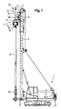
- Die Erfindung wird nachfolgend anhand bevorzugter Ausführungsbeispiele näher erläutert, die schematisch in den Figuren dargestellt sind. In den Figuren zeigen:
- Fig. 1
- ein erstes Ausführungsbeispiel eines erfindungsgemäßen Bohrgerätes;
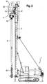
- Fig. 2
- ein zweites Ausführungsbeispiel eines erfindungsgemäßen Bohrgerätes;
- Fig. 3
- eine Detailansicht des Bohrgerätes aus Figur 2 im Bereich des Bohrantriebes; und
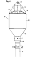
- Fig. 4
- einen Rohrbunker zur Verwendung in einem erfindungsgemäßen Bohrgerät.
- Gleich oder analog wirkende Elemente sind in allen Figuren mit denselben Bezugszeichen gekennzeichnet.
- Ein erstes Ausführungsbeispiel des erfindungsgemäßen Bohrgerätes ist in Figur 1 dargestellt. Das Bohrgerät weist ein Fahrgestell 1 auf, an dem ein Mast 2 verschwenkbar angeordnet ist. Am Mast 2 ist ein Schlitten 22 in einer Bohrrichtung längs des Mastes 2 verschiebbar vorgesehen.
- Am Schlitten 22 ist ein als Drehantrieb ausgebildeter Bohrantrieb 11 vorgesehen, an dessen Abtriebswelle 19 ein Bohrrohr 6 drehfest und beispielsweise axial fest angeordnet ist. Durch Betätigen des Bohrantriebes 11 kann das Bohrrohr 6 in Rotation versetzt werden. Durch Verfahren des Schlittens 22 kann das Bohrrohr 6 über den Bohrantrieb 11 axial in Bohrrichtung verschoben werden. Das Bohrrohr 6 ist mit der Abtriebswelle 19 über eine unten an der Abtriebswelle 19 angeordnete, lösbare Rohrkupplung 18 gekoppelt.
- Das Bohrrohr 6 ist mehrteilig mit mehreren Rohrelementen ausgebildet, die über lösbare Rohrkupplungen miteinander verbunden sind. Unten am Bohrrohr 6 ist ein Verdrängungsbohrkopf 80 vorgesehen.
- Der Bohrantrieb 11 weist ein Antriebsteil 12 auf, in dem ein Hydraulikdrehmotor angeordnet ist, sowie ein bodenseitig hieran angeordnetes, ringartiges Getriebeteil 13, das zur Drehmomentübertragung vom Hydraulikmotor zum Bohrrohr 6 dient.
- Zum Speichern von Füllgut ist oberhalb des Bohrrohres 6 in Verlängerung seiner Längsachse ein Rohrbunker 30 vorgesehen. Dieser Rohrbunker 30 weist einen zylindrischen Speicherbereich 33 zur Aufnahme von Füllgut auf, an den sich bodenseitig ein konischer Auslassbereich 34 anschließt. Der Rohrbunker 30 ist oberhalb des Bohrantriebes 11 und des Schlittens 22, das heißt auf der dem Bohrrohr 6 und insbesondere der Spitze des Bohrrohres 6 abgewandten Seite angeordnet. Somit kann der Bohrantrieb 11 bis an die Rohrkupplung 18 an den Erdboden herangefahren werden.
- Zum Einleiten von Füllgut aus dem Rohrbunker 30 in das Bohrrohr 6 ist unten am Auslassbereich 34 des Rohrbunkers 30 ein Verlängerungsrohr 40 angeordnet. Dieses Verlängerungsrohr 40 durchläuft das Antriebsteil 12, das Getriebeteil 13 und die als Hohlwelle ausgebildete Abtriebswelle 19 des Bohrantriebs 11 mittig und mündet in das Bohrrohr 6 ein. Das Füllgut kann somit aus dem Rohrbunker 30 durch das Verlängerungsrohr 40 und die Abtriebswelle 19 in das Bohrrohr 6 eingeleitet werden.
- Um eine Drehentkopplung des Rohrbunkers 30 vom Bohrrohr 6 zu ermöglichen, kann, beispielsweise am Verlängerungsrohr 40, eine Drehkupplung vorgesehen sein, die auch als Spülkopf bezeichnet werden kann.
- Der in Figur 1 dargestellte Rohrbunker 30 kann gegenüber dem Schlitten 22 und dem Bohrantrieb 11 höhenverstellbar, d.h. in der Bohrrichtung axial verstellbar am Schlitten 22 gelagert sein. Zum aktiven Verstellen kann beispielsweise das Verbindungsrohr 40 als eine Kellystange ausgebildet sein, welche Längsstege zur Drehmomentübertragung und Verriegeltaschen zum Aufbringen von Axialkräften aufweist.
- Ein weiteres Ausführungsbeispiel des erfindungsgemäßen Bohrgerätes ist in den Figuren 2 und 3 dargestellt. Das Ausführungsbeispiel der Figuren 2 und 3 unterscheidet sich vom Ausführungsbeispiel der Figur 1 im Wesentlichen dadurch, dass zum drehfesten Stützen und bevorzugt auch zum aktiven Höhenverstellen des Rohrbunkers 30 zwischen dem Schlitten 22 und insbesondere dem Bohrantrieb 11 einerseits und dem Rohrbunker 30 andererseits eine Stütze 50 vorgesehen ist, die in Bohrrichtung verläuft.
- Gemäß dem Ausführungsbeispiel der Figuren 2 und 3 ist zwischen dem Bohrrohr 6 und dem Rohrbunker 30 am Verbindungsrohr 40 eine Drehkupplung 60 angeordnet. Diese wird von einem Seitenarm der Stütze 50 gehalten. Sie sorgt für eine Drehentkopplung des Bohrrohres 6 vom Rohrbunker 30. Der Rohrbunker 30 ist dabei über die Stütze 50 drehfest bezüglich dem Bohrantrieb 11 und dem Schlitten 22 festgelegt.
- Ein weiteres Ausführungsbeispiel eines Rohrbunkers 30 zur Verwendung in einem erfindungsgemäßen Bohrgerät ist in Figur 4 dargestellt. Der Rohrbunker 30 der Figur 4 ist am oberen Ende des Speicherbereichs 33 durch einen konischen Deckel 36 verschlossen. In dem Deckel 36 sind Einfüllöffnungen 37 zum Einfüllen von Füllgut in den Speicherbereich 33 vorgesehen. Am Deckel 36 sind ferner verschiedenartige Ösen 38, 38' zum Anheben des Deckels 36 und/oder des Rohrbunkers 30 mittels eines Hilfskrans vorgesehen.
- Auslassseitig des Rohrbunkers 30 ist am Verbindungsrohr 40 eine als Klappe ausgebildete Verschlusseinrichtung 71 zum Absperren des Füllgutstromes zwischen Rohrbunker 30 und Bohrrohr 6 vorgesehen.
Claims (9)
- Bohrgerät zum Erstellen einer Bohrsäule im Boden mit- einem Mast (2),- einem Bohrantrieb (11), welcher an einem Schlitten (22) angeordnet ist, der entlang dem Mast (2) verschiebbar gelagert ist,- einem Bohrrohr (6), welches zum Erstellen eines Bohrlochs durch den Bohrantrieb (11) drehend antreibbar und entlang dem Mast (2) verschiebbar ist, und- einem am Bohrrohr (6) angeschlossenen Rohrbunker (30) mit einem Speicherraum für Füllmaterial zum Verfüllen des Bohrloches beim Ziehen des Bohrrohres (6),dadurch gekennzeichnet,
dass der Rohrbunker (30) in Bohrrichtung oberhalb des Bohrantriebes angeordnet und am Bohrrohr (6) angeschlossen ist. - Bohrgerät nach Anspruch 1,
dadurch gekennzeichnet,
dass der Rohrbunker (30) mit dem Schlitten (22) drehfest verbunden ist und relativ zum Bohrrohr (6) drehend gelagert ist. - Bohrgerät nach Anspruch 1 oder 2,
dadurch gekennzeichnet,
dass eine Verschlusseinrichtung (71) vorgesehen ist, durch welche ein Durchgang für Füllmaterial vom Rohrbunker (30) zum Bohrrohr (6) verschließbar ist. - Bohrgerät nach einem der Ansprüche 1 bis 3,
dadurch gekennzeichnet,
dass der Rohrbunker (30) gegenüber dem Schlitten (22) axial verschiebbar und feststellbar ist. - Bohrgerät nach einem der Ansprüche 1 bis 4,
dadurch gekennzeichnet,
dass das Bohrrohr (6) unterhalb des Bohrantriebes (11) drehfest und lösbar mit einer Abtriebswelle (19) des Bohrantriebes (11) verbunden ist. - Bohrgerät nach einem der Ansprüche 1 bis 5,
dadurch gekennzeichnet,
dass zum Messen eines Füllstandes im Rohrbunker (30) ein Füllstandssensor vorgesehen ist. - Bohrgerät nach einem der Ansprüche 1 bis 6,
dadurch gekennzeichnet,
dass die Abtriebswelle (19) des Bohrantriebes (11) als Hohlwelle ausgebildet ist, auf deren einen Seite das Bohrrohr (6) zumindest abschnittsweise verläuft und auf deren anderen Seite der Rohrbunker (30) angeordnet ist. - Bohrgerät nach einem der Ansprüche 1 bis 7,
dadurch gekennzeichnet,
dass der Rohrbunker (30) einen im Wesentlichen zylindrischen Speicherbereich (33) aufweist, an den sich unten ein im Wesentlichen konischer Auslassbereich (34) anschließt. - Verfahren zum Erstellen einer Bohrsäule im Boden, insbesondere mit einem Bohrgerät nach einem der Ansprüche 1 bis 8, bei dem- ein Bohrrohr (6) in den Boden mittels eines Bohrantriebes (11) drehend eingebracht wird, welcher an einem Schlitten (22) angeordnet ist, der entlang eines Mastes (2) in einer Bohrrichtung verschiebbar ist, und- nach Erreichen einer gewünschten Tiefe das Bohrrohr (6) zurückgezogen und das Bohrloch mit Füllmaterial aus einem Rohrbunker (30) über das Bohrrohr (6) verfüllt wird,dadurch gekennzeichnet,
dass der Rohrbunker (30) auf dem Schlitten (22) drehfest zu diesem angeordnet und mit diesem verschoben wird.
Priority Applications (14)
| Application Number | Priority Date | Filing Date | Title |
|---|---|---|---|
| ES06008683T ES2361849T3 (es) | 2006-04-26 | 2006-04-26 | Perforadora y procedimiento para crear una columna de perforación en el suelo. |
| PT06008683T PT1849918E (pt) | 2006-04-26 | 2006-04-26 | Perfuradora e m?todo para criar uma coluna de perfura??o no solo |
| EP06008683A EP1849918B1 (de) | 2006-04-26 | 2006-04-26 | Bohrgerät und Verfahren zum Erstellen einer Bohrsäule im Boden |
| DE502006009051T DE502006009051D1 (de) | 2006-04-26 | 2006-04-26 | Bohrgerät und Verfahren zum Erstellen einer Bohrsäule im Boden |
| PL06008683T PL1849918T3 (pl) | 2006-04-26 | 2006-04-26 | Urządzenie wiertnicze do wykonywania słupa wiertniczego w ziemi |
| AT06008683T ATE501312T1 (de) | 2006-04-26 | 2006-04-26 | Bohrgerät und verfahren zum erstellen einer bohrsäule im boden |
| CA2583608A CA2583608C (en) | 2006-04-26 | 2007-03-30 | Drilling device and method for producing a drilling column in the soil |
| SG200702959-8A SG136915A1 (en) | 2006-04-26 | 2007-04-18 | Drilling device and method for producing a drilling column in the soil |
| RU2007114759/03A RU2360070C2 (ru) | 2006-04-26 | 2007-04-19 | Буровая машина и способ возведения в грунте набивной сваи |
| JP2007113639A JP4505479B2 (ja) | 2006-04-26 | 2007-04-24 | 地中施工杭を作るための掘削装置および方法 |
| CNA200710101098XA CN101063400A (zh) | 2006-04-26 | 2007-04-26 | 钻孔装置和在土壤中产生钻柱的方法 |
| US11/790,689 US7713002B2 (en) | 2006-04-26 | 2007-04-26 | Drilling device and method for producing a drilling column in the soil |
| KR1020070040600A KR100882538B1 (ko) | 2006-04-26 | 2007-04-26 | 지면에 드릴링 기둥을 만들기 위한 드릴링 장치 및 이에의한 방법 |
| HK08101779.7A HK1112946B (en) | 2008-02-19 | Drilling apparatus and method to form a pillar in the ground by drilling |
Applications Claiming Priority (1)
| Application Number | Priority Date | Filing Date | Title |
|---|---|---|---|
| EP06008683A EP1849918B1 (de) | 2006-04-26 | 2006-04-26 | Bohrgerät und Verfahren zum Erstellen einer Bohrsäule im Boden |
Publications (2)
| Publication Number | Publication Date |
|---|---|
| EP1849918A1 true EP1849918A1 (de) | 2007-10-31 |
| EP1849918B1 EP1849918B1 (de) | 2011-03-09 |
Family
ID=36763137
Family Applications (1)
| Application Number | Title | Priority Date | Filing Date |
|---|---|---|---|
| EP06008683A Expired - Lifetime EP1849918B1 (de) | 2006-04-26 | 2006-04-26 | Bohrgerät und Verfahren zum Erstellen einer Bohrsäule im Boden |
Country Status (13)
| Country | Link |
|---|---|
| US (1) | US7713002B2 (de) |
| EP (1) | EP1849918B1 (de) |
| JP (1) | JP4505479B2 (de) |
| KR (1) | KR100882538B1 (de) |
| CN (1) | CN101063400A (de) |
| AT (1) | ATE501312T1 (de) |
| CA (1) | CA2583608C (de) |
| DE (1) | DE502006009051D1 (de) |
| ES (1) | ES2361849T3 (de) |
| PL (1) | PL1849918T3 (de) |
| PT (1) | PT1849918E (de) |
| RU (1) | RU2360070C2 (de) |
| SG (1) | SG136915A1 (de) |
Cited By (4)
| Publication number | Priority date | Publication date | Assignee | Title |
|---|---|---|---|---|
| EP3299522A1 (de) | 2016-09-27 | 2018-03-28 | BAUER Maschinen GmbH | Bohrgerät und verfahren zum erstellen einer bohrung |
| CN111335809A (zh) * | 2020-03-28 | 2020-06-26 | 福州市长乐区艾德利电子科技有限公司 | 一种用于桥梁桩基加工的钻孔设备 |
| WO2020192821A1 (de) * | 2019-03-28 | 2020-10-01 | Jannes Janitschke | Pfahlgründungsbohrgerät |
| EP3719246A1 (de) * | 2019-04-03 | 2020-10-07 | BAUER Maschinen GmbH | Verfahren zum erstellen einer bohrung im boden und bohrgerät hierfür |
Families Citing this family (12)
| Publication number | Priority date | Publication date | Assignee | Title |
|---|---|---|---|---|
| SI1849919T1 (sl) | 2006-04-26 | 2009-04-30 | Bauer Maschinen Gmbh | Vrtalna naprava in postopek za oblikovanje stebraste vrtine v podlago s pomoäśjo vrtanja |
| CN102134962B (zh) * | 2010-01-26 | 2013-12-04 | 如皋市名门电气材料有限公司 | 一种自动冲孔桩机 |
| EP2669436B1 (de) * | 2012-05-30 | 2014-12-31 | ABI Anlagentechnik-Baumaschinen-Industriebedarf Maschinenfabrik und Vertriebsgesellschaft mbH | Ramm- und Ziehvorrichtung |
| CN102912791B (zh) * | 2012-10-15 | 2015-06-10 | 中冶交通工程技术有限公司 | 一种钻孔灌注桩的施工方法 |
| HRP20170752T1 (hr) * | 2012-12-10 | 2017-08-11 | Jaron Lyell Mcmillan | Modificirana bušilica za bušenje stupova od zrnastog kamena |
| HUE049572T2 (hu) | 2017-10-06 | 2020-10-28 | Bauer Maschinen Gmbh | Eljárás egy cölöp készítésére talajban, valamint ehhez való talajmegmunkáló berendezés |
| CN110984894B (zh) * | 2019-12-25 | 2020-10-02 | 中南大学 | 一种导杆活叶卡取自锁式截齿取芯钻筒 |
| CN112127361A (zh) * | 2020-10-09 | 2020-12-25 | 山河智能装备股份有限公司 | 一种预制管桩植入设备及植桩施工方法 |
| CN116044305B (zh) * | 2021-01-04 | 2024-09-24 | 成都欣皓地基基础工程有限责任公司 | 方桩钻头及核心部件 |
| EP4098803B1 (de) * | 2021-05-31 | 2024-08-07 | ABI Anlagentechnik-Baumaschinen-Industriebedarf Maschinenfabrik und Vertriebsgesellschaft mbH | Rüttelstopflanze und verfahren zum rüsten eines mäklers mit einer rüttelstopflanze |
| AU2022372965A1 (en) * | 2021-10-18 | 2024-05-02 | Cameron Gaylard | A pile installation apparatus and method of use thereof |
| CN118757112B (zh) * | 2024-09-05 | 2024-11-05 | 枣庄矿业集团高庄煤业有限公司 | 一种用于煤矿开采的钻进设备 |
Citations (5)
| Publication number | Priority date | Publication date | Assignee | Title |
|---|---|---|---|---|
| US3303656A (en) * | 1962-12-21 | 1967-02-14 | Richard E Landau | Method and apparatus for constructing columns of material in soil |
| US3604214A (en) * | 1968-08-16 | 1971-09-14 | Lee A Turzillo | Means and method of making columnar structures in situ |
| EP0831180A1 (de) * | 1996-09-20 | 1998-03-25 | Gaspar Jozef Coelus | Stangenbohrer zur Herstellung eines Pfahls im Boden und Verfahren zum Anbringen dieses Pfahls |
| US20030123937A1 (en) * | 1999-09-01 | 2003-07-03 | Landau Richard E. | Apparatus to form columns of granular material |
| EP1580325A1 (de) * | 2004-03-26 | 2005-09-28 | BAUER Maschinen GmbH | Rohrbunker für die Aufnahme von Beton sowie Vorrichtung und Verfahren zum Herausziehen eines mehrteiligen Bohrrohrs aus einem Bohrloch und zum Verfüllen des Bohrlochs |
Family Cites Families (13)
| Publication number | Priority date | Publication date | Assignee | Title |
|---|---|---|---|---|
| JPS5139770B2 (de) * | 1972-06-28 | 1976-10-29 | ||
| GB1391109A (en) * | 1972-09-11 | 1975-04-16 | Turzillo L A | Method for producing pile or like structural columns in situ |
| US3831159A (en) * | 1973-05-02 | 1974-08-20 | W Parsons | High level and low level alarm for bins and hoppers |
| JPS547709A (en) * | 1977-06-20 | 1979-01-20 | Fudo Construction Co | Method of construction of forming compaction sand pile and its device |
| JPS59220521A (ja) * | 1983-05-30 | 1984-12-12 | Kurimoto Masafumi | 砂杭造成装置 |
| JPH0645930B2 (ja) * | 1988-03-04 | 1994-06-15 | 中富 栗本 | グラベル杭造成装置 |
| JP2535485B2 (ja) * | 1992-10-13 | 1996-09-18 | 中富 栗本 | サンドドレ―ン打設装置 |
| US5647690A (en) * | 1995-06-08 | 1997-07-15 | Landau; Richard Erwin | Low cost installation of columns of material |
| JP3712883B2 (ja) * | 1999-03-12 | 2005-11-02 | 不動建設株式会社 | 地盤改良杭造成装置 |
| US6517292B1 (en) * | 1999-09-01 | 2003-02-11 | Richard E Landau | Apparatus to form columns of granular material |
| RU2167097C1 (ru) * | 2000-04-18 | 2001-05-20 | Самарский институт инженеров железнодорожного транспорта | Бункер для сыпучих материалов |
| US7226246B2 (en) | 2000-06-15 | 2007-06-05 | Geotechnical Reinforcement, Inc. | Apparatus and method for building support piers from one or successive lifts formed in a soil matrix |
| JP2002105944A (ja) | 2000-09-28 | 2002-04-10 | Okutama Kogyo Co Ltd | 地盤改良方法 |
-
2006
- 2006-04-26 PT PT06008683T patent/PT1849918E/pt unknown
- 2006-04-26 DE DE502006009051T patent/DE502006009051D1/de not_active Expired - Lifetime
- 2006-04-26 ES ES06008683T patent/ES2361849T3/es not_active Expired - Lifetime
- 2006-04-26 AT AT06008683T patent/ATE501312T1/de active
- 2006-04-26 PL PL06008683T patent/PL1849918T3/pl unknown
- 2006-04-26 EP EP06008683A patent/EP1849918B1/de not_active Expired - Lifetime
-
2007
- 2007-03-30 CA CA2583608A patent/CA2583608C/en not_active Expired - Fee Related
- 2007-04-18 SG SG200702959-8A patent/SG136915A1/en unknown
- 2007-04-19 RU RU2007114759/03A patent/RU2360070C2/ru not_active IP Right Cessation
- 2007-04-24 JP JP2007113639A patent/JP4505479B2/ja not_active Expired - Fee Related
- 2007-04-26 CN CNA200710101098XA patent/CN101063400A/zh active Pending
- 2007-04-26 KR KR1020070040600A patent/KR100882538B1/ko not_active Expired - Fee Related
- 2007-04-26 US US11/790,689 patent/US7713002B2/en active Active
Patent Citations (5)
| Publication number | Priority date | Publication date | Assignee | Title |
|---|---|---|---|---|
| US3303656A (en) * | 1962-12-21 | 1967-02-14 | Richard E Landau | Method and apparatus for constructing columns of material in soil |
| US3604214A (en) * | 1968-08-16 | 1971-09-14 | Lee A Turzillo | Means and method of making columnar structures in situ |
| EP0831180A1 (de) * | 1996-09-20 | 1998-03-25 | Gaspar Jozef Coelus | Stangenbohrer zur Herstellung eines Pfahls im Boden und Verfahren zum Anbringen dieses Pfahls |
| US20030123937A1 (en) * | 1999-09-01 | 2003-07-03 | Landau Richard E. | Apparatus to form columns of granular material |
| EP1580325A1 (de) * | 2004-03-26 | 2005-09-28 | BAUER Maschinen GmbH | Rohrbunker für die Aufnahme von Beton sowie Vorrichtung und Verfahren zum Herausziehen eines mehrteiligen Bohrrohrs aus einem Bohrloch und zum Verfüllen des Bohrlochs |
Cited By (5)
| Publication number | Priority date | Publication date | Assignee | Title |
|---|---|---|---|---|
| EP3299522A1 (de) | 2016-09-27 | 2018-03-28 | BAUER Maschinen GmbH | Bohrgerät und verfahren zum erstellen einer bohrung |
| WO2020192821A1 (de) * | 2019-03-28 | 2020-10-01 | Jannes Janitschke | Pfahlgründungsbohrgerät |
| EP3719246A1 (de) * | 2019-04-03 | 2020-10-07 | BAUER Maschinen GmbH | Verfahren zum erstellen einer bohrung im boden und bohrgerät hierfür |
| WO2020200770A1 (de) * | 2019-04-03 | 2020-10-08 | Bauer Maschinen Gmbh | Verfahren zum erstellen einer bohrung im boden und bohrgerät hierfür |
| CN111335809A (zh) * | 2020-03-28 | 2020-06-26 | 福州市长乐区艾德利电子科技有限公司 | 一种用于桥梁桩基加工的钻孔设备 |
Also Published As
| Publication number | Publication date |
|---|---|
| ATE501312T1 (de) | 2011-03-15 |
| RU2007114759A (ru) | 2008-10-27 |
| US7713002B2 (en) | 2010-05-11 |
| KR20070105890A (ko) | 2007-10-31 |
| ES2361849T3 (es) | 2011-06-22 |
| CN101063400A (zh) | 2007-10-31 |
| PL1849918T3 (pl) | 2011-07-29 |
| CA2583608C (en) | 2010-10-19 |
| EP1849918B1 (de) | 2011-03-09 |
| RU2360070C2 (ru) | 2009-06-27 |
| CA2583608A1 (en) | 2007-10-26 |
| SG136915A1 (en) | 2007-11-29 |
| DE502006009051D1 (de) | 2011-04-21 |
| PT1849918E (pt) | 2011-05-31 |
| US20070267224A1 (en) | 2007-11-22 |
| JP4505479B2 (ja) | 2010-07-21 |
| JP2007291850A (ja) | 2007-11-08 |
| HK1112946A1 (en) | 2008-09-19 |
| KR100882538B1 (ko) | 2009-02-06 |
Similar Documents
| Publication | Publication Date | Title |
|---|---|---|
| EP1849918B1 (de) | Bohrgerät und Verfahren zum Erstellen einer Bohrsäule im Boden | |
| EP2295646B1 (de) | Bohrvorrichtung und Bohrverfahren | |
| DE2849022C2 (de) | Vorrichtung zum Ausheben von Erdlöchern | |
| EP1849919B1 (de) | Bohrgerät und Verfahren zum Erstellen einer Bohrsäule im Boden | |
| EP2770156B1 (de) | Bohrwerkzeug und Verfahren zum Erdbohren | |
| EP1978204B1 (de) | Erdbohrgerät | |
| EP2407629B1 (de) | Bohrvorrichtung und Bohrverfahren | |
| EP3877624B1 (de) | Kellystangenanordnung für ein bohrgerät und verfahren zur bodenbearbeitung | |
| WO2017016714A1 (de) | Bohrgerät und verfahren zum erstellen einer bohrung von einer schwimmenden plattform | |
| EP0645519B1 (de) | Bohrvorrichtung mit teleskopierbarer Kellystange | |
| EP1512631B1 (de) | Vorrichtung zum Befüllen eines Sackes | |
| DE19512070C2 (de) | Bohrgerät | |
| EP3299522B1 (de) | Bohrgerät und verfahren zum erstellen einer bohrung | |
| EP4455445B1 (de) | Bohrwerkzeug und verfahren zum erstellen einer bohrung im boden | |
| EP1580325B1 (de) | Rohrbunker für die Aufnahme von Beton sowie Vorrichtung und Verfahren zum Herausziehen eines mehrteiligen Bohrrohrs aus einem Bohrloch und zum Verfüllen des Bohrlochs | |
| EP3456914B1 (de) | Doppelkopf-bohrvorrichtung und verfahren zum erstellen einer bohrung | |
| EP1477633B1 (de) | Verfahren und Vorrichtung zur Bodenbearbeitung | |
| DE19642711A1 (de) | Vorrichtung und Verfahren zur kontrollierten Herstellung von Pfählen oder Pfahlwänden im Boden | |
| EP4372202A1 (de) | Im-loch-bohrgerät und verfahren zum erstellen einer bohrung im boden | |
| EP3392449B1 (de) | Bohrvorrichtung und bohrverfahren zum herstellen einer bohrung im boden | |
| EP1630299B1 (de) | Verfahren zur Fundamentsicherung sowie Bohr- und Mischwerkzeug | |
| EP4063565B1 (de) | Baumaschine, verdrängerrohr und verfahren zum erstellen einer füllgutsäule im boden | |
| EP4491843B1 (de) | Kastenbohrer und verfahren zum erstellen einer bohrung im boden | |
| DE102012006306A1 (de) | Reinigungsvorrichtung für eine Bohrschnecke | |
| DE102012010199B4 (de) | Verfahren und Vorrichtung zum Erstellen eines Bohrloches |
Legal Events
| Date | Code | Title | Description |
|---|---|---|---|
| PUAI | Public reference made under article 153(3) epc to a published international application that has entered the european phase |
Free format text: ORIGINAL CODE: 0009012 |
|
| 17P | Request for examination filed |
Effective date: 20061229 |
|
| AK | Designated contracting states |
Kind code of ref document: A1 Designated state(s): AT BE BG CH CY CZ DE DK EE ES FI FR GB GR HU IE IS IT LI LT LU LV MC NL PL PT RO SE SI SK TR |
|
| AX | Request for extension of the european patent |
Extension state: AL BA HR MK YU |
|
| AKX | Designation fees paid |
Designated state(s): AT BE BG CH CY CZ DE DK EE ES FI FR GB GR HU IE IS IT LI LT LU LV MC NL PL PT RO SE SI SK TR |
|
| REG | Reference to a national code |
Ref country code: HK Ref legal event code: DE Ref document number: 1112946 Country of ref document: HK |
|
| GRAP | Despatch of communication of intention to grant a patent |
Free format text: ORIGINAL CODE: EPIDOSNIGR1 |
|
| GRAS | Grant fee paid |
Free format text: ORIGINAL CODE: EPIDOSNIGR3 |
|
| GRAA | (expected) grant |
Free format text: ORIGINAL CODE: 0009210 |
|
| AK | Designated contracting states |
Kind code of ref document: B1 Designated state(s): AT BE BG CH CY CZ DE DK EE ES FI FR GB GR HU IE IS IT LI LT LU LV MC NL PL PT RO SE SI SK TR |
|
| REG | Reference to a national code |
Ref country code: GB Ref legal event code: FG4D Free format text: NOT ENGLISH |
|
| REG | Reference to a national code |
Ref country code: CH Ref legal event code: EP |
|
| REG | Reference to a national code |
Ref country code: IE Ref legal event code: FG4D Free format text: LANGUAGE OF EP DOCUMENT: GERMAN |
|
| REG | Reference to a national code |
Ref country code: CH Ref legal event code: NV Representative=s name: SCHMAUDER & PARTNER AG PATENT- UND MARKENANWAELTE |
|
| REF | Corresponds to: |
Ref document number: 502006009051 Country of ref document: DE Date of ref document: 20110421 Kind code of ref document: P |
|
| REG | Reference to a national code |
Ref country code: DE Ref legal event code: R096 Ref document number: 502006009051 Country of ref document: DE Effective date: 20110421 |
|
| REG | Reference to a national code |
Ref country code: HK Ref legal event code: GR Ref document number: 1112946 Country of ref document: HK |
|
| RAP2 | Party data changed (patent owner data changed or rights of a patent transferred) |
Owner name: BAUER MASCHINEN GMBH |
|
| REG | Reference to a national code |
Ref country code: PT Ref legal event code: SC4A Free format text: AVAILABILITY OF NATIONAL TRANSLATION Effective date: 20110524 |
|
| REG | Reference to a national code |
Ref country code: SE Ref legal event code: TRGR |
|
| REG | Reference to a national code |
Ref country code: NL Ref legal event code: T3 Ref country code: ES Ref legal event code: FG2A Ref document number: 2361849 Country of ref document: ES Kind code of ref document: T3 Effective date: 20110622 |
|
| PG25 | Lapsed in a contracting state [announced via postgrant information from national office to epo] |
Ref country code: LT Free format text: LAPSE BECAUSE OF FAILURE TO SUBMIT A TRANSLATION OF THE DESCRIPTION OR TO PAY THE FEE WITHIN THE PRESCRIBED TIME-LIMIT Effective date: 20110309 Ref country code: LV Free format text: LAPSE BECAUSE OF FAILURE TO SUBMIT A TRANSLATION OF THE DESCRIPTION OR TO PAY THE FEE WITHIN THE PRESCRIBED TIME-LIMIT Effective date: 20110309 Ref country code: GR Free format text: LAPSE BECAUSE OF FAILURE TO SUBMIT A TRANSLATION OF THE DESCRIPTION OR TO PAY THE FEE WITHIN THE PRESCRIBED TIME-LIMIT Effective date: 20110610 |
|
| PGFP | Annual fee paid to national office [announced via postgrant information from national office to epo] |
Ref country code: CH Payment date: 20110418 Year of fee payment: 6 Ref country code: PT Payment date: 20110531 Year of fee payment: 6 Ref country code: SE Payment date: 20110521 Year of fee payment: 6 Ref country code: FR Payment date: 20110511 Year of fee payment: 6 Ref country code: ES Payment date: 20110419 Year of fee payment: 6 |
|
| REG | Reference to a national code |
Ref country code: PL Ref legal event code: T3 |
|
| LTIE | Lt: invalidation of european patent or patent extension |
Effective date: 20110309 |
|
| PG25 | Lapsed in a contracting state [announced via postgrant information from national office to epo] |
Ref country code: BG Free format text: LAPSE BECAUSE OF FAILURE TO SUBMIT A TRANSLATION OF THE DESCRIPTION OR TO PAY THE FEE WITHIN THE PRESCRIBED TIME-LIMIT Effective date: 20110609 Ref country code: SI Free format text: LAPSE BECAUSE OF FAILURE TO SUBMIT A TRANSLATION OF THE DESCRIPTION OR TO PAY THE FEE WITHIN THE PRESCRIBED TIME-LIMIT Effective date: 20110309 Ref country code: CY Free format text: LAPSE BECAUSE OF FAILURE TO SUBMIT A TRANSLATION OF THE DESCRIPTION OR TO PAY THE FEE WITHIN THE PRESCRIBED TIME-LIMIT Effective date: 20110309 |
|
| PGFP | Annual fee paid to national office [announced via postgrant information from national office to epo] |
Ref country code: NL Payment date: 20110510 Year of fee payment: 6 Ref country code: GB Payment date: 20110414 Year of fee payment: 6 Ref country code: PL Payment date: 20110426 Year of fee payment: 6 Ref country code: HU Payment date: 20110421 Year of fee payment: 6 Ref country code: FI Payment date: 20110419 Year of fee payment: 6 Ref country code: AT Payment date: 20110421 Year of fee payment: 6 |
|
| REG | Reference to a national code |
Ref country code: HU Ref legal event code: AG4A Ref document number: E010890 Country of ref document: HU |
|
| REG | Reference to a national code |
Ref country code: IE Ref legal event code: FD4D |
|
| PG25 | Lapsed in a contracting state [announced via postgrant information from national office to epo] |
Ref country code: IE Free format text: LAPSE BECAUSE OF FAILURE TO SUBMIT A TRANSLATION OF THE DESCRIPTION OR TO PAY THE FEE WITHIN THE PRESCRIBED TIME-LIMIT Effective date: 20110309 Ref country code: EE Free format text: LAPSE BECAUSE OF FAILURE TO SUBMIT A TRANSLATION OF THE DESCRIPTION OR TO PAY THE FEE WITHIN THE PRESCRIBED TIME-LIMIT Effective date: 20110309 |
|
| PG25 | Lapsed in a contracting state [announced via postgrant information from national office to epo] |
Ref country code: RO Free format text: LAPSE BECAUSE OF FAILURE TO SUBMIT A TRANSLATION OF THE DESCRIPTION OR TO PAY THE FEE WITHIN THE PRESCRIBED TIME-LIMIT Effective date: 20110309 Ref country code: SK Free format text: LAPSE BECAUSE OF FAILURE TO SUBMIT A TRANSLATION OF THE DESCRIPTION OR TO PAY THE FEE WITHIN THE PRESCRIBED TIME-LIMIT Effective date: 20110309 Ref country code: CZ Free format text: LAPSE BECAUSE OF FAILURE TO SUBMIT A TRANSLATION OF THE DESCRIPTION OR TO PAY THE FEE WITHIN THE PRESCRIBED TIME-LIMIT Effective date: 20110309 Ref country code: MC Free format text: LAPSE BECAUSE OF NON-PAYMENT OF DUE FEES Effective date: 20110430 Ref country code: IS Free format text: LAPSE BECAUSE OF FAILURE TO SUBMIT A TRANSLATION OF THE DESCRIPTION OR TO PAY THE FEE WITHIN THE PRESCRIBED TIME-LIMIT Effective date: 20110709 |
|
| PLBE | No opposition filed within time limit |
Free format text: ORIGINAL CODE: 0009261 |
|
| STAA | Information on the status of an ep patent application or granted ep patent |
Free format text: STATUS: NO OPPOSITION FILED WITHIN TIME LIMIT |
|
| 26N | No opposition filed |
Effective date: 20111212 |
|
| PG25 | Lapsed in a contracting state [announced via postgrant information from national office to epo] |
Ref country code: DK Free format text: LAPSE BECAUSE OF FAILURE TO SUBMIT A TRANSLATION OF THE DESCRIPTION OR TO PAY THE FEE WITHIN THE PRESCRIBED TIME-LIMIT Effective date: 20110309 |
|
| REG | Reference to a national code |
Ref country code: DE Ref legal event code: R097 Ref document number: 502006009051 Country of ref document: DE Effective date: 20111212 |
|
| REG | Reference to a national code |
Ref country code: NL Ref legal event code: V1 Effective date: 20121101 |
|
| REG | Reference to a national code |
Ref country code: CH Ref legal event code: PL |
|
| REG | Reference to a national code |
Ref country code: SE Ref legal event code: EUG |
|
| REG | Reference to a national code |
Ref country code: AT Ref legal event code: MM01 Ref document number: 501312 Country of ref document: AT Kind code of ref document: T Effective date: 20120426 |
|
| GBPC | Gb: european patent ceased through non-payment of renewal fee |
Effective date: 20120426 |
|
| REG | Reference to a national code |
Ref country code: FR Ref legal event code: ST Effective date: 20121228 |
|
| PG25 | Lapsed in a contracting state [announced via postgrant information from national office to epo] |
Ref country code: HU Free format text: LAPSE BECAUSE OF NON-PAYMENT OF DUE FEES Effective date: 20120427 Ref country code: LI Free format text: LAPSE BECAUSE OF NON-PAYMENT OF DUE FEES Effective date: 20120430 Ref country code: AT Free format text: LAPSE BECAUSE OF NON-PAYMENT OF DUE FEES Effective date: 20120426 Ref country code: CH Free format text: LAPSE BECAUSE OF NON-PAYMENT OF DUE FEES Effective date: 20120430 Ref country code: FI Free format text: LAPSE BECAUSE OF NON-PAYMENT OF DUE FEES Effective date: 20120426 Ref country code: GB Free format text: LAPSE BECAUSE OF NON-PAYMENT OF DUE FEES Effective date: 20120426 |
|
| REG | Reference to a national code |
Ref country code: PT Ref legal event code: MM4A Free format text: LAPSE DUE TO NON-PAYMENT OF FEES Effective date: 20130128 |
|
| PG25 | Lapsed in a contracting state [announced via postgrant information from national office to epo] |
Ref country code: SE Free format text: LAPSE BECAUSE OF NON-PAYMENT OF DUE FEES Effective date: 20120427 Ref country code: FR Free format text: LAPSE BECAUSE OF NON-PAYMENT OF DUE FEES Effective date: 20120430 |
|
| PG25 | Lapsed in a contracting state [announced via postgrant information from national office to epo] |
Ref country code: NL Free format text: LAPSE BECAUSE OF NON-PAYMENT OF DUE FEES Effective date: 20121101 |
|
| PG25 | Lapsed in a contracting state [announced via postgrant information from national office to epo] |
Ref country code: PT Free format text: LAPSE BECAUSE OF NON-PAYMENT OF DUE FEES Effective date: 20130128 Ref country code: LU Free format text: LAPSE BECAUSE OF NON-PAYMENT OF DUE FEES Effective date: 20110426 |
|
| REG | Reference to a national code |
Ref country code: PL Ref legal event code: LAPE |
|
| PG25 | Lapsed in a contracting state [announced via postgrant information from national office to epo] |
Ref country code: PL Free format text: LAPSE BECAUSE OF NON-PAYMENT OF DUE FEES Effective date: 20120426 |
|
| PG25 | Lapsed in a contracting state [announced via postgrant information from national office to epo] |
Ref country code: TR Free format text: LAPSE BECAUSE OF FAILURE TO SUBMIT A TRANSLATION OF THE DESCRIPTION OR TO PAY THE FEE WITHIN THE PRESCRIBED TIME-LIMIT Effective date: 20110309 |
|
| PG25 | Lapsed in a contracting state [announced via postgrant information from national office to epo] |
Ref country code: ES Free format text: LAPSE BECAUSE OF NON-PAYMENT OF DUE FEES Effective date: 20120427 |
|
| REG | Reference to a national code |
Ref country code: ES Ref legal event code: FD2A Effective date: 20131031 |
|
| REG | Reference to a national code |
Ref country code: DE Ref legal event code: R082 Ref document number: 502006009051 Country of ref document: DE Representative=s name: WUNDERLICH & HEIM PATENTANWAELTE PARTNERSCHAFT, DE |
|
| P01 | Opt-out of the competence of the unified patent court (upc) registered |
Effective date: 20230510 |
|
| PGFP | Annual fee paid to national office [announced via postgrant information from national office to epo] |
Ref country code: IT Payment date: 20230403 Year of fee payment: 18 Ref country code: DE Payment date: 20230411 Year of fee payment: 18 |
|
| PGFP | Annual fee paid to national office [announced via postgrant information from national office to epo] |
Ref country code: BE Payment date: 20240409 Year of fee payment: 19 |
|
| REG | Reference to a national code |
Ref country code: DE Ref legal event code: R119 Ref document number: 502006009051 Country of ref document: DE |
|
| PG25 | Lapsed in a contracting state [announced via postgrant information from national office to epo] |
Ref country code: DE Free format text: LAPSE BECAUSE OF NON-PAYMENT OF DUE FEES Effective date: 20241105 |
|
| PG25 | Lapsed in a contracting state [announced via postgrant information from national office to epo] |
Ref country code: DE Free format text: LAPSE BECAUSE OF NON-PAYMENT OF DUE FEES Effective date: 20241105 |
|
| PG25 | Lapsed in a contracting state [announced via postgrant information from national office to epo] |
Ref country code: IT Free format text: LAPSE BECAUSE OF NON-PAYMENT OF DUE FEES Effective date: 20240426 |
|
| REG | Reference to a national code |
Ref country code: BE Ref legal event code: MM Effective date: 20250430 |
|
| PG25 | Lapsed in a contracting state [announced via postgrant information from national office to epo] |
Ref country code: BE Free format text: LAPSE BECAUSE OF NON-PAYMENT OF DUE FEES Effective date: 20250430 |