EP1848878B1 - Schaltbarer schlepphebel eines ventiltriebs einer brennkraftmaschine - Google Patents
Schaltbarer schlepphebel eines ventiltriebs einer brennkraftmaschine Download PDFInfo
- Publication number
- EP1848878B1 EP1848878B1 EP06706392.5A EP06706392A EP1848878B1 EP 1848878 B1 EP1848878 B1 EP 1848878B1 EP 06706392 A EP06706392 A EP 06706392A EP 1848878 B1 EP1848878 B1 EP 1848878B1
- Authority
- EP
- European Patent Office
- Prior art keywords
- lever
- piston
- rocker arm
- coupling
- driving surface
- Prior art date
- Legal status (The legal status is an assumption and is not a legal conclusion. Google has not performed a legal analysis and makes no representation as to the accuracy of the status listed.)
- Expired - Fee Related
Links
Images

Classifications
-
- F—MECHANICAL ENGINEERING; LIGHTING; HEATING; WEAPONS; BLASTING
- F01—MACHINES OR ENGINES IN GENERAL; ENGINE PLANTS IN GENERAL; STEAM ENGINES
- F01L—CYCLICALLY OPERATING VALVES FOR MACHINES OR ENGINES
- F01L1/00—Valve-gear or valve arrangements, e.g. lift-valve gear
- F01L1/12—Transmitting gear between valve drive and valve
- F01L1/18—Rocking arms or levers
- F01L1/185—Overhead end-pivot rocking arms
-
- F—MECHANICAL ENGINEERING; LIGHTING; HEATING; WEAPONS; BLASTING
- F01—MACHINES OR ENGINES IN GENERAL; ENGINE PLANTS IN GENERAL; STEAM ENGINES
- F01L—CYCLICALLY OPERATING VALVES FOR MACHINES OR ENGINES
- F01L1/00—Valve-gear or valve arrangements, e.g. lift-valve gear
- F01L1/12—Transmitting gear between valve drive and valve
- F01L1/18—Rocking arms or levers
- F01L2001/186—Split rocking arms, e.g. rocker arms having two articulated parts and means for varying the relative position of these parts or for selectively connecting the parts to move in unison
-
- Y—GENERAL TAGGING OF NEW TECHNOLOGICAL DEVELOPMENTS; GENERAL TAGGING OF CROSS-SECTIONAL TECHNOLOGIES SPANNING OVER SEVERAL SECTIONS OF THE IPC; TECHNICAL SUBJECTS COVERED BY FORMER USPC CROSS-REFERENCE ART COLLECTIONS [XRACs] AND DIGESTS
- Y10—TECHNICAL SUBJECTS COVERED BY FORMER USPC
- Y10T—TECHNICAL SUBJECTS COVERED BY FORMER US CLASSIFICATION
- Y10T74/00—Machine element or mechanism
- Y10T74/21—Elements
- Y10T74/2101—Cams
- Y10T74/2107—Follower
Definitions
- the invention relates to a rocker arm of a valve train of an internal combustion engine, which is switchable to different strokes for at least one gas exchange valve, with an outer and between its arms extending and pivotable relative to this inner lever, wherein at one end of the lever extending in a lever longitudinal direction Drill hole is applied with a piston, which piston is partially slidable with its top under a driver surface of one end of the other lever, so that in this coupling a large and decoupling a small or 0-valve stroke is generated, wherein at an underside of the finger lever at one end a system for a gas exchange valve and the other end a complementary surface for a support element is applied and wherein at least the decoupling in the decoupling lever on its upper side is acted upon by at least one cognitivehubnocken.
- a generic rocker arm goes out of the DE 103 18 295 A1 out. Its piston as a coupling means extends in a bore at one end of the inner member and can for the coupling case sections under a corresponding complementarily shaped driving surface of a crossbar of the outer lever are displaced.
- document EP 1 408 203 discloses a similar valve train.
- the object of the invention is therefore to provide a switchable drag lever of the aforementioned type, in which the disadvantageous "edge support" are eliminated by simple means.
- this object is achieved in that the piston is provided in its coupling region, as well as starting from its lying in the coupling direction, either with a rising, radii-like profiling or with a sloping, radii profiling, the driver surface of the other lever follows the profiling cone-like and wherein in coupling a contact point of the piston is located on the driving surface in the region of half the depth of the driving surface.
- this object is solved by the features of the independent claim 2, according to which the piston is shown smooth cylindrical, wherein at coupling whose contact point on the driver surface is in the region of half the depth of the driver surface and wherein the driver surface, starting from the contact point, on both sides with a sloping Radial profiling is provided.
- a contact point of the piston on the driver surface should lie approximately in the region of half the depth of the driver surface.
- the aforementioned contact point is at least not to be found in the region of the edges of the complementary surface at their ends.
- the proposed radius profiling on the piston can be generated for example by sliding or belt grinding.
- driver surface is the subject of another subclaim. Accordingly, it should be represented, for example, as an indentation on an underside of a crossbeam of the respective other lever, for example the outer lever. However, it is also conceivable and intended to represent the driver surface as part of a bore of a crossbar of the other lever.
- the bore with the piston in the inner lever above a formed, for example, as a dome-shaped indentation complementary surface for the support element, to arrange and thus displace the piston for its coupling case longitudinally outward under the corresponding cam surface.
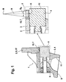
- FIG. 1 discloses a switchable rocker arm 1, as he from its basic structure in the aforementioned DE 103 18 295 A1 is described. As a further reference is at this point the US 5,544,626 called, but in which the piston extends in a bore of the outer lever.
- the drag lever 1 consists of an outer lever 2, between the arms, not shown, which is shown here only in the region of its one end 4 inner lever 3 is added.
- the arms of the outer lever 2 are in the range its one end 8 connected by a crossbar 17. It can also be seen that in the region of the end 4 of the inner lever 3, on the underside 9, a dome-shaped complementary surface 11 is applied. This serves to support the inner and thus the entire drag lever 3, 1 on a head of a support member not shown in the drawing.
- the coupling region of the piston 6 is shown pulled out enlarged.
- a smooth cylindrical piston 6 is present.
- the condition at coupling can be recognized.
- the driving surface 7, starting from the contact point K, on both sides with a sloping, radii-like profiling 15 is provided.
- the contact point K is approximately in the range of half a depth or here at half the thickness of the crossbar 17 of the driver surface 7. Due to this profiling according to the invention is no longer in coupling to the aforementioned, adverse "edge beams".
- the piston 6 has in its coupling region a sloping radii profiling 14. This starts from its lying in the coupling direction of the forehead 12.
- the region B P of the profiling is at least pulled over the coupling portion of the piston 6.
- “R” stands in all figures for the radius of Profili e-tion and "M” for its center, which of course can be elsewhere.
- the driver surface 7 follows the profiling 14 approximately cone-like.
- the contact point K is in this case again in the region of half the depth of the driver surface 7.
- FIG. 2 different profiling shows FIG. 3 , Accordingly, the piston 6 has on its outer shell, starting from its outer end 12, an increasing, radii-like profiling 13. This in turn is the cone-like following cam surface 7 opposite.
- the term "half depth" is related to the insertion region of the piston 6 when coupled.
Landscapes
- Engineering & Computer Science (AREA)
- Mechanical Engineering (AREA)
- General Engineering & Computer Science (AREA)
- Actuator (AREA)
- Valve Device For Special Equipments (AREA)
- Valve-Gear Or Valve Arrangements (AREA)
Description
- Die Erfindung betrifft einen Schlepphebel eines Ventiltriebs einer Brennkraftmaschine, der auf unterschiedliche Hübe für wenigstens ein Gaswechselventil umschaltbar ist, mit einem Außen- und einem zwischen dessen Armen verlaufenden und relativ zu diesem verschwenkbeweglichen Innenhebel, wobei an einem Ende eines der Hebel eine sich in Hebellängsrichtung erstreckende Bohrung mit einem Kolben appliziert ist, welcher Kolben mit seiner Oberseite abschnittsweise unter eine Mitnehmerfläche eines Endes des jeweils anderen Hebels schiebbar ist, so dass bei dieser Kopplung ein großer und bei Entkopplung ein kleiner oder 0-Ventilhub generiert ist, wobei an einer Unterseite des Schlepphebels einenends eine Anlage für ein Gaswechselventil und anderenends eine Komplementärfläche für ein Abstützelement appliziert ist und wobei zumindest der im Entkoppelfall abschwenkende Hebel an seiner Oberseite von wenigstens einem Großhubnocken beaufschlagbar ist.
- Ein gattungsgemäßer Schlepphebel geht aus der
DE 103 18 295 A1 hervor. Dessen Kolben als Koppelmittel verläuft in einer Bohrung an einem Ende des Innenelements und kann für den Koppelfall abschnittsweise unter eine entsprechend komplementär ausgebildete Mitnehmerfläche eines Querbalkens des Außenhebels verlagert werden. DokumentEP 1 408 203 offenbart einen ähnlichen ventiltrieb. - Aufgrund der Geometrie der Kopplung (konvex in konkav) sowie durch fertigungstechnische Ungenauigkeiten bzw. funktionsbedingte Spiele kann es während des Betriebes des Nockenfolgers im Koppelfall zu sogenannten "Kantenträgern" kommen. Diese sind unerwünscht und rühren vor allem daher, dass eine eingangs- oder ausgangsseitige Kante der Mitnehmerfläche bei Kopplung hauptsächlich trägt. Aufgrund dieser erhöhten und unerwünschten Kontaktpressungen kann es zu einem Einschlag im Koppelbereich kommen, so dass wiederum das Spiel der Kopplung vergrößert wird. Dieses Spiel muss jedoch in engen Toleranzgrenzen gehalten werden, um eine ordnungsgemäße Funktion des Ventiltriebs über dessen Lebensdauer hinweg zu garantieren. Unter Umständen kann es aufgrund der vorgenannten "Kantenträger" auch zu einem Abtrag von Spänen kommen, die zu einem Verklemmen des jeweiligen Kolbens führen können.
- Aufgabe der Erfindung ist es daher, einen schaltbaren Schlepphebel der vorgenannten Art zu schaffen, bei dem die nachteiligen "Kantenträger" mit einfachen Mitteln beseitigt sind.
- Erfindungsgemäß wird diese Aufgabe dadurch gelöst, dass der Kolben in seinem Koppelbereich, sowie ausgehend von seiner in Koppelrichtung liegenden Stirn, entweder mit einer ansteigenden, radienhaften Profilierung oder mit einer abfallenden, radienhaften Profilierung versehen ist, wobei die Mitnehmerfläche des anderen Hebels der Profilierung konusartig folgt und wobei bei Kopplung ein Kontaktpunkt des Kolbens an der Mitnehmerfläche im Bereich einer halben Tiefe der Mitnehmerfläche liegt.
- Alternativ wird diese Aufgabe durch die Merkmale des nebengeordneten Anspruchs 2 gelöst, wonach der Kolben glattzylindrisch dargestellt ist, wobei bei Kopplung dessen Kontaktpunkt an der Mitnehmerfläche im Bereich einer halben Tiefe der Mitnehmerfläche liegt und wobei die Mitnehmerfläche, ausgehend von dem Kontaktpunkt, beidseits mit einer abfallenden, radienhaften Profilierung versehen ist.
- Somit liegt ein schaltbarer Schlepphebel vor, bei dem es aufgrund der erfindungsgemäßen, radienhaften Profilierung nicht mehr zu den eingangs genannten "Kantenträgern" kommt. Ein Kontaktpunkt des Kolbens an der Mitnehmerfläche soll dabei in etwa im Bereich einer halben Tiefe der Mitnehmerfläche liegen. Mit vom Schutzumfang der Erfindung eingeschlossen ist jedoch auch eine Lösung, bei der der vorgenannte Kontaktpunkt wenigstens nicht im Bereich der Kanten der Komplementärfläche an ihren Enden zu finden ist.
- Somit liegt durch die erfindungsgemäßen Maßnahmen im Koppelbereich quasi ein Punktkontakt vor, welcher sich nach Beginn des Betriebes des Ventiltriebs noch setzt. Der Konstrukteur wird hier ein entsprechendes Maß vorhalten.
- Die vorgeschlagene Radienprofilierung am Kolben kann beispielsweise durch Gleit- oder Bandschleifen erzeugt werden.
- Eine einfache Ausbildung der Mitnehmerfläche ist Gegenstand eines weiteren Unteranspruchs. Demnach soll diese beispielsweise als Einformung an einer Unterseite eines Querbalkens des jeweils anderen Hebels, beispielsweise des Außenhebels, dargestellt sein. Es ist jedoch auch denkbar und vorgesehen, die Mitnehmerfläche als Bestandteil einer Bohrung eines Querbalkens des jeweils anderen Hebels darzustellen.
- Gemäß einer weiteren Konkretisierung der Erfindung ist es vorgesehen, die Bohrung mit dem Kolben im Innenhebel, oberhalb einer beispielsweise als kalottenförmige Einformung ausgebildeten Komplementärfläche für das Abstützelement, anzuordnen und den Kolben somit für dessen Koppelfall längs nach außen unter die entsprechende Mitnehmerfläche zu verlagern.
- Schließlich ist es vorgeschlagen, die Bohrung für den Kolben im Innenhebel als Durchgangsbohrung zu fertigen. Diese Maßnahme ist fertigungstechnisch besonders günstig.
- Die Erfindung ist zwar insbesondere bei Schlepphebeln mit dem Design "Längsverriegetung" einsetzbar, jedoch nicht ausschließlich. Gleichfalls bezieht sich der Schutzbereich auch auf schaltbare Schlepphebel mit einer so genannten "Querverriegelung" bzw. auf andere schaltbare Ventiltriebskomponenten wie Schwinghebeltriebe etc.
- Die Erfindung ist zweckmäßigerweise anhand der Zeichnung näher erläutert. Es zeigen:
- Figur 1
- Den erfindungsgemäßen Schlepphebel im Teillängsschnitt mit vergrößert dargestelltem Koppelbereich und die
- Figuren 2, 3
- Varianten der Profilierung des Kolbens als Koppelmittel.
-
Figur 1 offenbart einen schaltbaren Schlepphebel 1, so wie er von seinem grundsätzlichen Aufbau in der eingangs genanntenDE 103 18 295 A1 beschrieben ist. Als weitere Referenz wird an dieser Stelle dieU.S. 5,544,626 genannt, bei der jedoch der Kolben in einer Bohrung des Außenhebels verläuft. - Der Schlepphebel 1 besteht aus einem Außenhebel 2, zwischen dessen nicht dargestellten Armen der hier lediglich im Bereich seines einen Endes 4 gezeigte Innenhebel 3 aufgenommen ist. Die Arme des Außenhebels 2 sind im Bereich ihres einen Endes 8 durch einen Querbalken 17 verbunden. Zu erkennen ist zudem, dass im Bereich des Endes 4 des Innenhebels 3, an dessen Unterseite 9, eine kalottenförmige Komplementärfläche 11 appliziert ist. Diese dient einer Lagerung des Innen- und somit des gesamten Schlepphebels 3, 1 auf einem Kopf eines zeichnerisch nicht dargestellten Abstützelements.
- Oberhalb der Komplementärfläche 11 verläuft im Innenhebel 3 eine als Durchgangsbohrung ausgebildete Bohrung 5. In dieser sitzt im Entkoppelfall ein Kolben 6 als Koppelmittel. In sämtlichen Figuren ist der Kolben 6 in seiner Koppelstellung gezeigt. Dabei untergreift er mit seinem Außenmantel eine Mitnehmerfläche 7 des Querbalkens 17 des Außenhebels 2.
- In der rechten Bildhälfte der
Figur 1 ist der Koppelbereich des Kolbens 6 vergrößert herausgezogen dargestellt. Gemäß der hier offenbarten Variante liegt ein glattzylindrischer Kolben 6 vor. Zu erkennen ist der Zustand bei Kopplung. Dabei ist die Mitnehmerfläche 7, ausgehend von dem Kontaktpunkt K, beidseits mit einer abfallenden, radienhaften Profilierung 15 versehen. Der Kontaktpunkt K liegt etwa im Bereich einer halben Tiefe bzw. hier bei einer halben Dicke des Querbalkens 17 der Mitnehmerfläche 7. Aufgrund dieser erfindungsgemäßen Profilierung kommt es bei Kopplung nicht mehr zu den eingangs genannten, nachteiligen "Kantenträgern". - Eine alternative Ausgestaltung gegenüber
Figur 1 offenbartFigur 2 . Demnach hat der Kolben 6 in seinem Koppelbereich eine abfallend radienhafte Profilierung 14. Diese beginnt von seiner in Koppelrichtung liegenden Stirn 12. Dabei ist der Bereich BP der Profilierung zumindest über den Koppelabschnitt des Kolbens 6 gezogen. "R" steht dabei in allen Figuren für den Radius der Profili e-rung und "M" für dessen Mittelpunkt, der selbstverständlich auch anderenorts liegen kann. Die Mitnehmerfläche 7 folgt der Profilierung 14 etwa konusartig. Der Kontaktpunkt K liegt hier wiederum im Bereich einer halben Tiefe der Mitnehmerfläche 7. - Eine gegenüber
Figur 2 anders verlaufende Profilierung zeigtFigur 3 . Demnach hat der Kolben 6 an seinem Außenmantel, ausgehend von seiner äußeren Stirn 12, eine ansteigende, radienhafte Profilierung 13. Dieser liegt wiederum die konusartig folgende Mitnehmerfläche 7 gegenüber. - Sollte die Mitnehmerfläche 7 beispielsweise eine Bohrung wie eine Sackbohrung sein, so ist der Begriff "halbe Tiefe" auf den Einschubbereich des Kolbens 6 bei Kopplung bezogen.
-
- 1) Schlepphebel
- 2) Außenhebel
- 3) Innenhebel
- 4) Ende
- 5) Bohrung
- 6) Kolben
- 7) Mitnehmerfläche
- 8) Ende
- 9) Unterseite
- 10)nicht vergeben
- 11)Komplementärfläche
- 12)Stim
- 13)Profilierung
- 14)Pröfilierung
- 15)Profilierung
- 16)Unterseite
- 17)Querbalken
- M) Radiusmittelpunkt
- K) Kontaktpunkt
- BP) Bereich Profilierung
- R) Radius / Lotrechte
Claims (5)
- Schlepphebel (1) eines Ventiltriebs einer Brennkraftmaschine, der auf unterschiedliche Hübe für wenigstens ein Gaswechselventil umschaltbar ist, mit einem Außen- und einem zwischen dessen Armen verlaufenden und relativ zu diesem verschwenkbeweglichen Innenhebel (2, 3), wobei an einem Ende (4) eines der Hebel (3 oder 2) eine sich in Hebellängsrichtung erstreckende Bohrung (5) mit einem Kolben (6) appliziert ist, welcher Kolben (6) mit seiner Oberseite abschnittsweise unter eine Mitnehmerfläche (7) eines Endes (8) des jeweils anderen Hebels (2, 3) schiebbar ist, so dass bei dieser Kopplung ein großer und bei Entkopplung ein kleiner oder 0-Ventilhub generiert ist, wobei an einer Unterseite (9) des Schlepphebels (1) einenends eine Anlage für ein Gaswechselventil und anderenends eine Komplementärfläche (11) für ein Abstützelement appliziert ist und wobei zumindest der im Entkoppelfall abschwenkende Hebel (2, 3) an seiner Oberseite von wenigstens einem Großhubnocken beaufschlagbar ist, dadurch gekennzeichnet, dass der Kolben (6) in seinem Koppelbereich sowie ausgehend von seiner in Koppelrichtung liegenden Stirn (12) entweder mit einer ansteigenden, radienhaften Profilierung (13) oder mit einer abfallenden, radienhaften Profilierung (14) versehen ist, wobei die Mitnehmerfläche (7) des anderen Hebels (2, 3) der Profilierung (13, 14) konusartig folgt und wobei bei Kopplung ein Kontaktpunkt (K) des Kolbens (6) an der Mitnehmerfläche (7) im Bereich einer halben Tiefe der Mitnehmerfläche (7) liegt.
- Schlepphebel nach dem Oberbegriff des Anspruchs 1, wobei der Kolben (6) glattzylindrisch dargestellt ist, dadurch gekennzeichnet, dass bei Kopplung dessen Kontaktpunkt (K) an der Mitnehmerfläche (7) im Bereich einer halben Tiefe der Mitnehmerfläche (7) liegt und wobei die Mitnehmerfläche (7), ausgehend von dem Kontaktpunkt (K), beidseits mit einer abfallenden, radienhaften Profilierung (15) versehen ist.
- Schlepphebel nach Anspruch 1 oder 2, dadurch gekennzeichnet, dass die Mitnehmerfläche (7) entweder als Einformung an einer Unterseite (16) eines Querbalken (17) oder als Bestandteil einer Bohrung eines Querbalken (17) am Ende (8) des jeweils anderen Hebels (2, 3) vorliegt.
- Schlepphebel nach einem der vorgenannten Ansprüche, dadurch gekennzeichnet, dass der Innenhebel (3) mit der Anlage für das Gaswechselventil und der Komplementärfläche (11) für das Abstützelement versehen ist, wobei die Bohrung (5) mit dem Kolben (6) oberhalb oder seitlich der Komplementärfläche (11) für das Abstützelement im Innenhebel (3) verläuft.
- Schlepphebel nach Anspruch 4, dadurch gekennzeichnet, dass die Bohrung (5) für den Kolben (6) im Innenhebel (3) als Durchgangsbohrung ausgebildet ist.
Applications Claiming Priority (2)
| Application Number | Priority Date | Filing Date | Title |
|---|---|---|---|
| DE102005006954A DE102005006954A1 (de) | 2005-02-16 | 2005-02-16 | Schaltbarer Schlepphebel eines Ventiltriebs einer Brennkraftmaschine |
| PCT/EP2006/000621 WO2006087076A1 (de) | 2005-02-16 | 2006-01-25 | Schaltbarer schlepphebel eines ventiltriebs einer brennkraftmaschine |
Publications (2)
| Publication Number | Publication Date |
|---|---|
| EP1848878A1 EP1848878A1 (de) | 2007-10-31 |
| EP1848878B1 true EP1848878B1 (de) | 2013-04-17 |
Family
ID=36096346
Family Applications (1)
| Application Number | Title | Priority Date | Filing Date |
|---|---|---|---|
| EP06706392.5A Expired - Fee Related EP1848878B1 (de) | 2005-02-16 | 2006-01-25 | Schaltbarer schlepphebel eines ventiltriebs einer brennkraftmaschine |
Country Status (4)
| Country | Link |
|---|---|
| US (1) | US7503300B2 (de) |
| EP (1) | EP1848878B1 (de) |
| DE (1) | DE102005006954A1 (de) |
| WO (1) | WO2006087076A1 (de) |
Families Citing this family (5)
| Publication number | Priority date | Publication date | Assignee | Title |
|---|---|---|---|---|
| USD833482S1 (en) | 2015-07-13 | 2018-11-13 | Eaton Corporation | Rocker arm |
| USD791190S1 (en) | 2015-07-13 | 2017-07-04 | Eaton Corporation | Rocker arm assembly |
| USD830414S1 (en) | 2015-12-10 | 2018-10-09 | Eaton S.R.L. | Roller rocker arm of an engine |
| US10753237B2 (en) * | 2018-05-29 | 2020-08-25 | Schaeffler Technologies AG & Co. KG | Actuation arrangement for switchable lever |
| DE102022116589A1 (de) | 2022-07-04 | 2024-01-04 | Schaeffler Technologies AG & Co. KG | Anordnung zum Koppeln von beweglich zueinander angeordneten Bauteilen für eine schaltbare Ventiltriebkomponente einer Brennkraftmaschine |
Family Cites Families (7)
| Publication number | Priority date | Publication date | Assignee | Title |
|---|---|---|---|---|
| US5544626A (en) | 1995-03-09 | 1996-08-13 | Ford Motor Company | Finger follower rocker arm with engine valve deactivator |
| DE19630309C2 (de) | 1996-07-06 | 2001-10-11 | Meta Motoren Energietech | Vorrichtung zum Unterbrechen des Kraftflusses zwischen einer Nockenwelle und mindestens einem Ventil |
| DE10038917A1 (de) | 2000-08-09 | 2002-02-21 | Fev Motorentech Gmbh | Kolbenbrennkraftmaschine mit deaktivierbaren, mechanisch betätigbaren Gaswechselventilen |
| US6805083B2 (en) * | 2002-10-10 | 2004-10-19 | Ford Global Technologies, Llc | Cam cover gasket |
| DE10310220A1 (de) | 2003-03-08 | 2004-09-16 | Daimlerchrysler Ag | Vorrichtung zur Koppelung bzw. Entkoppelung zweier Betätigungshebel eines Ventiltriebes einer Brennkraftmaschine und Verfahren hierzu |
| DE102004007766A1 (de) | 2003-03-20 | 2004-09-30 | Ina-Schaeffler Kg | Schlepphebel eines Ventiltriebs einer Brennkraftmaschine |
| DE10318295A1 (de) * | 2003-04-23 | 2004-11-11 | Ina-Schaeffler Kg | Schlepphebel eines Ventiltriebs einer Brennkraftmaschine |
-
2005
- 2005-02-16 DE DE102005006954A patent/DE102005006954A1/de not_active Withdrawn
-
2006
- 2006-01-25 US US11/816,466 patent/US7503300B2/en not_active Expired - Fee Related
- 2006-01-25 EP EP06706392.5A patent/EP1848878B1/de not_active Expired - Fee Related
- 2006-01-25 WO PCT/EP2006/000621 patent/WO2006087076A1/de active Application Filing
Also Published As
| Publication number | Publication date |
|---|---|
| US7503300B2 (en) | 2009-03-17 |
| DE102005006954A1 (de) | 2006-08-17 |
| US20080264368A1 (en) | 2008-10-30 |
| WO2006087076A1 (de) | 2006-08-24 |
| EP1848878A1 (de) | 2007-10-31 |
Similar Documents
| Publication | Publication Date | Title |
|---|---|---|
| EP1616082B1 (de) | Schlepphebel eines ventiltriebs einer brennkraftmaschine | |
| EP2013450B1 (de) | Schaltbarer schlepphebel eines ventiltriebs einer brennkraftmaschine | |
| DE102006007489B4 (de) | Verriegelungsanordnung für eine Ventilabschaltungseinrichtung | |
| EP1785595A1 (de) | Schaltbarer Schlepphebel eines Ventiltriebs einer Brennkraftmaschine | |
| DE102005037052A1 (de) | Schaltbarer Schlepphebel eines Ventiltriebs einer Brennkraftmaschine | |
| EP2226477B1 (de) | Hydraulikeinheit für einen Zylinderkopf einer Brennkraftmaschine mit hydraulisch variablem Gaswechselventiltrieb | |
| EP1848878B1 (de) | Schaltbarer schlepphebel eines ventiltriebs einer brennkraftmaschine | |
| DE102008030794A1 (de) | Koppeleinrichtung eines schaltbaren Schlepphebels eines Ventiltriebs einer Brennkraftmaschine | |
| DE102007011892A1 (de) | Schaltbares Abstützelement für einen Ventiltrieb einer Brennkraftmaschine | |
| EP1881165A2 (de) | Schaltbarer Ventiltrieb für eine Brennkraftmaschine | |
| DE10310226A1 (de) | Schlepphebel eines Ventiltriebs einer Brennkraftmaschine | |
| DE102007031810A1 (de) | Schaltbarer Ventiltrieb für eine Brennkraftmaschine | |
| WO2008043717A2 (de) | Schlepphebel | |
| EP2295739B1 (de) | Ventiltrieb einer Brennkraftmaschine | |
| DE102007011893A1 (de) | Schaltbares Abstützelement für einen Ventiltrieb einer Brennkraftmaschine | |
| EP2142767B9 (de) | Schaltbarer tassenstössel | |
| EP1357257A2 (de) | Hebelartiger Nockenfolger aus Blech | |
| DE19818146A1 (de) | Ventiltrieb einer Brennkraftmaschine | |
| DE102009019680A1 (de) | Ventiltriebssystem | |
| DE102007008409A1 (de) | Ventiltrieb einer Brennkraftmaschine mit einem Schlepphebel | |
| DE102005059027A1 (de) | Hebelartiger Nockenfolger | |
| DE19930574A1 (de) | Ventiltrieb einer Brennkraftmaschine | |
| DE102005059701A1 (de) | Bauteil für einen Ventiltrieb einer Brennkraftmaschine | |
| DE102012218661A1 (de) | Hebelartiger Nockenfolger | |
| DE102006051256A1 (de) | Ventiltriebs-Hebel für eine Brennkraftmaschine |
Legal Events
| Date | Code | Title | Description |
|---|---|---|---|
| PUAI | Public reference made under article 153(3) epc to a published international application that has entered the european phase |
Free format text: ORIGINAL CODE: 0009012 |
|
| 17P | Request for examination filed |
Effective date: 20070730 |
|
| AK | Designated contracting states |
Kind code of ref document: A1 Designated state(s): DE FR GB IT SE |
|
| DAX | Request for extension of the european patent (deleted) | ||
| RBV | Designated contracting states (corrected) |
Designated state(s): DE FR GB IT SE |
|
| RAP1 | Party data changed (applicant data changed or rights of an application transferred) |
Owner name: SCHAEFFLER TECHNOLOGIES AG & CO. KG |
|
| GRAP | Despatch of communication of intention to grant a patent |
Free format text: ORIGINAL CODE: EPIDOSNIGR1 |
|
| GRAS | Grant fee paid |
Free format text: ORIGINAL CODE: EPIDOSNIGR3 |
|
| GRAA | (expected) grant |
Free format text: ORIGINAL CODE: 0009210 |
|
| AK | Designated contracting states |
Kind code of ref document: B1 Designated state(s): DE FR GB IT SE |
|
| REG | Reference to a national code |
Ref country code: GB Ref legal event code: FG4D Free format text: NOT ENGLISH |
|
| REG | Reference to a national code |
Ref country code: DE Ref legal event code: R096 Ref document number: 502006012739 Country of ref document: DE Effective date: 20130613 |
|
| PG25 | Lapsed in a contracting state [announced via postgrant information from national office to epo] |
Ref country code: SE Free format text: LAPSE BECAUSE OF FAILURE TO SUBMIT A TRANSLATION OF THE DESCRIPTION OR TO PAY THE FEE WITHIN THE PRESCRIBED TIME-LIMIT Effective date: 20130417 |
|
| REG | Reference to a national code |
Ref country code: DE Ref legal event code: R097 Ref document number: 502006012739 Country of ref document: DE |
|
| PLBE | No opposition filed within time limit |
Free format text: ORIGINAL CODE: 0009261 |
|
| STAA | Information on the status of an ep patent application or granted ep patent |
Free format text: STATUS: NO OPPOSITION FILED WITHIN TIME LIMIT |
|
| PG25 | Lapsed in a contracting state [announced via postgrant information from national office to epo] |
Ref country code: IT Free format text: LAPSE BECAUSE OF FAILURE TO SUBMIT A TRANSLATION OF THE DESCRIPTION OR TO PAY THE FEE WITHIN THE PRESCRIBED TIME-LIMIT Effective date: 20130417 |
|
| RAP2 | Party data changed (patent owner data changed or rights of a patent transferred) |
Owner name: SCHAEFFLER TECHNOLOGIES GMBH & CO. KG |
|
| 26N | No opposition filed |
Effective date: 20140120 |
|
| REG | Reference to a national code |
Ref country code: DE Ref legal event code: R081 Ref document number: 502006012739 Country of ref document: DE Owner name: SCHAEFFLER TECHNOLOGIES GMBH & CO. KG, DE Free format text: FORMER OWNER: SCHAEFFLER TECHNOLOGIES AG & CO. KG, 91074 HERZOGENAURACH, DE Effective date: 20140218 Ref country code: DE Ref legal event code: R081 Ref document number: 502006012739 Country of ref document: DE Owner name: SCHAEFFLER TECHNOLOGIES AG & CO. KG, DE Free format text: FORMER OWNER: SCHAEFFLER TECHNOLOGIES AG & CO. KG, 91074 HERZOGENAURACH, DE Effective date: 20140218 Ref country code: DE Ref legal event code: R081 Ref document number: 502006012739 Country of ref document: DE Owner name: SCHAEFFLER TECHNOLOGIES AG & CO. KG, DE Free format text: FORMER OWNER: SCHAEFFLER KG, 91074 HERZOGENAURACH, DE Effective date: 20130418 Ref country code: DE Ref legal event code: R081 Ref document number: 502006012739 Country of ref document: DE Owner name: SCHAEFFLER TECHNOLOGIES GMBH & CO. KG, DE Free format text: FORMER OWNER: SCHAEFFLER KG, 91074 HERZOGENAURACH, DE Effective date: 20130418 |
|
| REG | Reference to a national code |
Ref country code: DE Ref legal event code: R097 Ref document number: 502006012739 Country of ref document: DE Effective date: 20140120 |
|
| REG | Reference to a national code |
Ref country code: DE Ref legal event code: R081 Ref document number: 502006012739 Country of ref document: DE Owner name: SCHAEFFLER TECHNOLOGIES AG & CO. KG, DE Free format text: FORMER OWNER: SCHAEFFLER TECHNOLOGIES GMBH & CO. KG, 91074 HERZOGENAURACH, DE Effective date: 20150223 |
|
| REG | Reference to a national code |
Ref country code: FR Ref legal event code: PLFP Year of fee payment: 11 |
|
| REG | Reference to a national code |
Ref country code: FR Ref legal event code: PLFP Year of fee payment: 12 |
|
| PGFP | Annual fee paid to national office [announced via postgrant information from national office to epo] |
Ref country code: FR Payment date: 20170126 Year of fee payment: 12 |
|
| PGFP | Annual fee paid to national office [announced via postgrant information from national office to epo] |
Ref country code: GB Payment date: 20170131 Year of fee payment: 12 |
|
| PGFP | Annual fee paid to national office [announced via postgrant information from national office to epo] |
Ref country code: DE Payment date: 20180329 Year of fee payment: 13 |
|
| GBPC | Gb: european patent ceased through non-payment of renewal fee |
Effective date: 20180125 |
|
| PG25 | Lapsed in a contracting state [announced via postgrant information from national office to epo] |
Ref country code: FR Free format text: LAPSE BECAUSE OF NON-PAYMENT OF DUE FEES Effective date: 20180131 |
|
| REG | Reference to a national code |
Ref country code: FR Ref legal event code: ST Effective date: 20180928 |
|
| PG25 | Lapsed in a contracting state [announced via postgrant information from national office to epo] |
Ref country code: GB Free format text: LAPSE BECAUSE OF NON-PAYMENT OF DUE FEES Effective date: 20180125 |
|
| REG | Reference to a national code |
Ref country code: DE Ref legal event code: R119 Ref document number: 502006012739 Country of ref document: DE |
|
| PG25 | Lapsed in a contracting state [announced via postgrant information from national office to epo] |
Ref country code: DE Free format text: LAPSE BECAUSE OF NON-PAYMENT OF DUE FEES Effective date: 20190801 |
|
| P01 | Opt-out of the competence of the unified patent court (upc) registered |
Effective date: 20230522 |