EP1848282B1 - Conveyor device for slaughtered poultry - Google Patents
Conveyor device for slaughtered poultry Download PDFInfo
- Publication number
- EP1848282B1 EP1848282B1 EP06700354A EP06700354A EP1848282B1 EP 1848282 B1 EP1848282 B1 EP 1848282B1 EP 06700354 A EP06700354 A EP 06700354A EP 06700354 A EP06700354 A EP 06700354A EP 1848282 B1 EP1848282 B1 EP 1848282B1
- Authority
- EP
- European Patent Office
- Prior art keywords
- carrier
- conveyor device
- drive member
- carriers
- coupling
- Prior art date
- Legal status (The legal status is an assumption and is not a legal conclusion. Google has not performed a legal analysis and makes no representation as to the accuracy of the status listed.)
- Expired - Lifetime
Links
Images


Classifications
-
- A—HUMAN NECESSITIES
- A22—BUTCHERING; MEAT TREATMENT; PROCESSING POULTRY OR FISH
- A22C—PROCESSING MEAT, POULTRY, OR FISH
- A22C21/00—Processing poultry
- A22C21/0053—Transferring or conveying devices for poultry
-
- A—HUMAN NECESSITIES
- A22—BUTCHERING; MEAT TREATMENT; PROCESSING POULTRY OR FISH
- A22C—PROCESSING MEAT, POULTRY, OR FISH
- A22C21/00—Processing poultry
- A22C21/0046—Support devices
-
- B—PERFORMING OPERATIONS; TRANSPORTING
- B65—CONVEYING; PACKING; STORING; HANDLING THIN OR FILAMENTARY MATERIAL
- B65G—TRANSPORT OR STORAGE DEVICES, e.g. CONVEYORS FOR LOADING OR TIPPING, SHOP CONVEYOR SYSTEMS OR PNEUMATIC TUBE CONVEYORS
- B65G47/00—Article or material-handling devices associated with conveyors; Methods employing such devices
- B65G47/74—Feeding, transfer, or discharging devices of particular kinds or types
- B65G47/84—Star-shaped wheels or devices having endless travelling belts or chains, the wheels or devices being equipped with article-engaging elements
- B65G47/846—Star-shaped wheels or wheels equipped with article-engaging elements
- B65G47/847—Star-shaped wheels or wheels equipped with article-engaging elements the article-engaging elements being grippers
Definitions
- the invention relates to a conveyor device for conveying slaughtered poultry or pieces of slaughtered poultry, comprising a plurality of carriers, each suitable for carrying slaughtered poultry or one or more parts thereof, at least one guide which supports the carriers and guides them such that they can move in a conveying direction, a drive member which advances parallel to the guide for jointly driving a plurality of carriers in the conveying direction, and also coupling means associated with each carrier for coupling the carrier to the drive member.
- a conveyor device of this type is known, for example, from EP 0 259 920 in the name of the present Applicant.
- the carrier is in this case an overhanging hook which is known from EP 0 155 014 , likewise in the name of the present Applicant, which in a conveyor device, in this case a transfer station, can transfer pieces of slaughtered poultry from a first processing line to a second processing line.
- the known conveyor device has a fixed annular guide track with a drive ring driven continuously in the conveying direction arranged concentrically with it, which two elements interact with the overhanging hooks.
- the overhanging hooks are guided along the annular guide track by means of sets of running wheels and are driven in the conveying direction by the rotating drive ring via friction blocks.
- the coupling means are thus formed by a friction block located on each overhanging hook.
- An accumulation zone is, for example, a buffer in which the carriers form a waiting line.
- a blocking stop retains two hooks, with the result that they are no longer advanced by the drive ring, but rather bear in a slipping manner against it. Subsequent hooks also come to bear against one another and then bear against the drive ring in a slipping manner by way of their friction blocks.
- the blocking stop is generally released after a signal indicating that one or more hooks are permitted to advance further.
- the object of the invention is to provide an improved conveyor device.
- a conveyor device according to the invention, the conveyor device also being provided with decoupling means, which are actuable by an actuating member, for selectively decoupling one or more of the carriers from the drive member.
- decoupled carriers if they are held in a stationary position, for example in a buffer, do not exert any braking action on the drive member.
- the drive means will be less prone to wear.
- a carrier On account of the possibility of selective decoupling, it is possible for a carrier to be decoupled as desired. For example, in regions where driving by the drive member is desired, it is possible to realize a fixed coupling. In particular in the case of a frictional coupling, it is then possible to ensure a good grip between the carriers and the drive member, even if the coupling means and/or the drive member become moist or wet in use.
- a carrier according to the invention therefore, the coupling force between carrier and drive member during conveying can be increased for each carrier compared to the known device, while the overall loading on the drive member remains constant or may even be reduced, on account of the fact that the coupling force of a plurality of carriers is eliminated by the decoupling, for example in a buffer.
- the coupling means effect a frictional coupling between the carrier and the drive member.
- a frictional coupling is realized if the drive member comprises a friction surface and the carrier comprises a friction block.
- a coupling of this type. has proven reliable for driving purposes, provided that wear is low, and is also simple to decouple.
- decoupling the friction-based coupling means of a carrier is that wear to the coupling means is prevented in regions where or at times at which driving of the carriers is not desired, for example in a buffer.
- a decoupled state the carrier is still connected to the guide, but the drive member continues to move without this decoupled carrier.
- the carrier is then, for example, stationary with respect to the advancing drive member.
- the coupling means will not then become worn, with the result that its engagement with the drive member no longer deteriorates undesirably over the course of time.
- the coupling means is then coupled to the drive member again, the carrier is again driven along the guide in the conveying direction by the drive member. If, for example, the coupling means used is a friction block, in the decoupled state this block will no longer be connected in a slipping manner to the drive member, which would cause it to become worn.
- the drive member comprises a rotating wheel with a frictional surface, with which the coupling means form a frictional coupling.
- An alternative drive member is, for example, a chain, a wire, a belt, a drum or a. disc, which advances parallel to the guide and by which a plurality of carriers can be jointly driven in the conveying direction.
- the coupling means effect a magnetic coupling between the carrier and the drive member.
- the drive member comprises a magnetic strip, by which the coupling means comprising a magnetic part of opposite polarity are attracted, so that the coupling means are connected to the drive member in the coupled state.
- the decoupling means are then preferably likewise magnetic or electrical, with the result that the coupling magnet can be deactivated and activated.
- a circuit is closed when carriers come into contact with one another, with the result that a movement of a coupling magnet which decouples the coupling magnet from the drive member is effected.
- the guide comprises a rail, such as the known rail shown in EP 0 259 920 .
- the carrier may, for example, be connected to the rail by means of sets of running rollers, so that the rail supports the carrier both when the carrier is coupled to the drive member and in the decoupled state.
- the guide comprises a recess arranged along the drive member, in which part of the carrier can engage, in such a manner that when the carrier is not connected to the drive member, it is connected to the recess.
- the recess is located circumferentially around a wheel around which a friction belt acts as drive member.
- the coupling means is connected to the carrier and designed in the form of a single body, which simplifies the structure.
- the decoupling means and the actuating member of the decoupling means are also connected to a carrier.
- an actuating member connected to a first carrier can decouple a coupling means connected to a second carrier. It is thus possible, in a buffer, for a second carrier, which is located behind a first carrier as seen in the conveying direction and catches up the first carrier, to be decoupled by decoupling means on the first carrier, provided that the carriers come into contact with one another with sufficient force and continue to bear against one another.
- a second carrier which catches up a first carrier to decouple a first carrier.
- first carriers are retained by a blocking stop. If carriers which catch up these first carriers are decoupled by these first carriers, they will no longer be driven in a slipping manner, which reduces the force acting on the drive member.
- the blocking stop which controls the waiting line does not interact with the decoupling mechanism and the front carrier is therefore coupled in the usual way. As a result, this front carrier, if desired, can be conveyed onwards immediately.
- the carriers which catch it up are preferably decoupled immediately, so that the load on the drive member decreases immediately.
- decoupling by means of an actuating member connected to a carrier is that decoupling can be used not only at fixed positions along a fixed section, but also for buffers of varying length or in the event of pile-ups.
- the actuating member of the decoupling means comprises a projecting activation bearing which can actuate the decoupling means arranged on another carrier.
- the actuating member of the decoupling means comprises an external mechanism that is not connected to the carrier.
- decoupling means can be remotely actuated.
- the coupling and decoupling can be programmed or can take place in response to certain sensor signals. For example, coupling and therefore conveying of the carrier by means of the drive member in the conveying direction takes place if a sensor indicates that there is space in a specific production line to process poultry arranged on carriers. Coupling can also take place after a certain interval, when a product on the carrier has undergone a specific treatment in a buffer zone. Consideration may also be given to a carrier with a sensor which decouples itself if the sensor indicates that another carrier is coming (too) close.
- the decoupling means comprise mechanical means, such as for example a lever.
- this lever is arranged on top of the carrier.' A projecting activation member of a carrier which then catches it up can actuate the lever of a carrier in front of it in the conveying direction and can thereby decouple the coupling means.
- the lever can move the coupling means to and fro perpendicular to the drive member and thereby couple and decouple it.
- the decoupling means comprise electrical means, pneumatic means or magnetic means.
- the invention also relates to a carrier which is suitable for use in a conveyor device as described above.
- the invention relates to a method for conveying slaughtered poultry or one or more pieces thereof, in which use is made of a conveyor device as described above.
- the conveying of poultry can be controlled to the extent that carriers can be selectively decoupled from the drive member when desired.
- the invention relates to a method for conveying slaughtered poultry, in which the slaughtered poultry or one or more pieces thereof are conveyed in a conveying device as described above.
- this method one or more of the carriers can be selectively decoupled from the drive member.
- carriers can be decoupled, so that the force exerted on the drive member by the carriers is reduced.
- an actuating member of decoupling means which are connected to a first carrier decouples coupling means of a second carrier.
- a carrier which catches up decouples the carrier which is in front of it and is being retained, or alternatively the carrier which is in front and is being retained decouples the carrier which catches it up.
- a plurality of carriers form a waiting line in a buffer, one or more carriers are decoupled in the buffer.
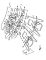
- Fig. 1 shows a view from below of an exemplary embodiment of a conveyor device 1 according to the invention for conveying at least one piece of slaughtered poultry (not shown).
- the conveyor device which is to be described in more detail below, is designed as a transfer means between two conveyor paths, in particular as a buffer transfer means.
- the conveyor device 1 comprises a plurality of carriers 2, two 2 and 2' of which are shown here, each suitable for carrying the slaughtered poultry (not shown).
- the carrier shown here which is known per se, the legs of slaughtered poultry can be suspended in the cutouts 2a.
- the conveyor device 1 also comprises a guide 5, which supports the carriers 2 and guides them such that they can move in a conveying direction A.
- the guide 5 is in this case designed as a rail with a substantially square cross section and three recesses 5a, 5b and 5c, within which guide wheels 6 can advance. In the embodiment shown, only wheels 6 in the recess 5a are visible.
- the carriers 2 are connected to the rail 5 in such a manner that they cannot simply fall off it.
- the guide 5 is enclosed within the carrier 2 inside the three guide wheels 6.
- the conveyor device 1 comprises a drive member 3 which advances parallel to the guide and can be used to move a plurality of carriers 2 jointly in the conveying direction A, as well as coupling means 4 associated with each carrier 2, by means of which coupling means the carriers 2 can be coupled to the drive member 3.
- the drive member 3 is in this case based on a mechanical principle and comprises an endlessly advancing rotating wheel with a friction belt, against which coupling means 4 designed as friction blocks press in the coupled state.
- the coupling means 4 designed as friction blocks are connected to the carrier.
- the friction blocks comprise a friction surface (not shown), which in the coupled state effects a frictional coupling between the carrier and the drive member.
- the right-hand carrier 2 is coupled to the drive member 3 by means of the coupling means 4.
- the left-hand carrier 2' is not coupled to the drive member 3; it can be seen that the coupling means 4 is a certain distance away from the drive member 3. However, the guide wheels 6 can still be supported on the guide 5, with the result that the carrier 2' remains connected to the guide 5.
- the coupling means 4 between the carriers 2 and the drive member 3 can be decoupled by means of decoupling means 7.
- the decoupling means 7 comprise a projecting activation bearing 7b and a lever 7a, each arranged on a different side of the carrier 2.
- a blocking stop 9 in front of a first carrier 2'.
- This blocking stop prevents carrier 2' from advancing in the direction A, irrespective of whether or not it is coupled to the drive member 3 via the coupling means 4.
- the carrier 2' comes into contact with the blocking stop 9, it will still be in a coupled state and will therefore be connected in a slipping manner to the friction belt 3.
- a second carrier 2 has run into the first carrier 2'.
- the projecting activation bearing 7b of the second carrier 2 comes into contact with the lever 7a of a first carrier 2', the lever 7a of the first carrier 2' decouples the friction block 4 of the first carrier 2', with the result that the first carrier 2' is no longer driven by the friction belt 3, as shown in Fig. 1 .
- the projecting activation bearing 7b moves a first part 7a' of the lever in the direction indicated by arrow B, and then the first part 7a' moves a second part of the lever 7a'' in the direction indicated by arrow C, with the result that the coupling means 4 connected to this second part 7a" is uncoupled from the drive member 3.
- lever 7a' If the lever 7a' is not activated by a projecting activation bearing and is in an at-rest position, springs arranged on both parts of the lever 7a' and 7a" ensure that the coupling means 4 remain coupled to the drive member 3. These springs are compressed in the coupled, activated state.
- the second carrier 2 will push the first carrier 2' onwards, since the second carrier 2 is coupled to the drive member 3 and is therefore advancing in direction A. If the force with which the second carrier 2 pushes against the first carrier 2' is high enough, the springs of the lever parts 7a' and 7a" will remain depressed and the first carrier 2' will remain decoupled. If this force is insufficiently high, the springs of the lever parts 7a' and 7a" will spring back to their starting position, in which the friction block 4 is once again pressed against the drive member 3 and the carrier 2' is in the coupled state. This will also occur if the second carrier 2 encounters the blockage 9 which was previously blocking the first carrier 2'. The second carrier 2 then no longer pushes on the first carrier 2' at all, and consequently the lever mechanism thereof will spring back into the coupled state.
- Fig. 2 shows a view from below of an alternative embodiment of a conveyor device 10 according to the invention.
- the conveyor device comprises the same type of carriers 2 and 2', guide 5 with recesses 5a, 5b and 5c, drive member 3 and coupling means 4 as shown in Fig. 1 .
- the decoupling means 70 comprise a sensor 70c connected to a pneumatic decoupling 70b which can decouple the coupling means 4 from the drive member 3. If the sensor 70c is activated by an activation 70a from a carrier located nearby, the pneumatic decoupling means 70b are energized and decouple the coupling means 4. It is possible for the sensor used to be a light sensor and for the activation 70a used to be a small plate which can cover the sensor and thereby changes the light signal which is received.
- a blocking member 9 is located next to the right-hand carrier 2.
- the latter cannot advance in the conveying direction A, even though the coupling means 4 of carrier 2 are engaging on the drive member 3.
- the carrier 2 is therefore connected in a slipping manner to the drive member 3.
- the sensor 70c of the carrier 2' which catches up the carrier 2 receives a signal from the signal generator 70a of the right-hand carrier 2, with the result that pneumatic means 70b on the left-hand carrier 2' decouple the coupling means 4 of the left-hand carrier 2'.
- the carriers which are catching up are thus decoupled.
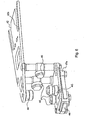
- Fig. 3 shows a side view of a second alternative embodiment of a conveyor device 20 according to the invention.
- the conveyor device 20 comprises a guide 50 with a recess 50a which runs next to the drive member 3.
- Carrier 21 with cutouts 21a for, for example, legs of poultry is connected to the guide 50 by means of a projection 21b in the recess 50a.
- the carrier 21 is connected to the drive member 3 with the aid of coupling means 4.
- the coupling means 4 can be decoupled with the aid of decoupling means 8.
- the decoupling means 8 comprise a lever 8b and a projecting activation bearing 8a which can actuate the lever 8b.
- FIG. 4 shows a third alternative embodiment of a carrier 30 in accordance with the invention.
- This carrier 30 is suitable to be guided along a guide such as the rail 5 shown in Fig. 1 and Fig. 2 with recesses 5a, 5b and 5c, along which recesses 5a, 5b and 5c guide wheels 31 can advance.
- the carrier 30 comprises coupling means 34 with teeth 34a which can engage on a gear wheel, chain or rubber conveyor belt with teeth on the outside, used as the guide.
- the carrier 30 comprises a projecting activation bearing 37a and a lever 37b, which together form the decoupling means.
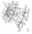
- FIGs 5 - 9 show a fourth alternative embodiment of a conveyor device 40 according to the invention.
- the conveyor device 40 comprises a plurality of carriers 42, two 42 and 42' of which are shown in Fig. 5 , each suitable for carrying the slaughtered poultry (not shown).
- the carrier shown here which is known per se, the legs of slaughtered poultry can be suspended in the cutouts 42a.
- the conveyor device 40 also comprises a guide 45 along which the carriers 42 can move in a conveying direction A and to which each of the carriers 42 is connected.
- the guide 45 is in this case designed as a rail with a substantially square cross section with three recesses 45a, 45b and 45c, in which guide wheels 46 can advance.
- the conveyor device 40 comprises a drive member 43 which advances parallel to the guide and by which a plurality of carriers 42 can be jointly moved in the conveying direction A, as well as coupling means 44 associated with each carrier 42, by which the carriers 42 can be coupled to the drive member 43.
- the drive member 43 is in this case based on a mechanical principle and includes an endlessly advancing rotating wheel with a friction belt, against which coupling means 44 designed as friction blocks press in the coupled state.
- the coupling means 44 designed as friction blocks are connected to the carrier.
- the friction blocks 44 comprise a friction surface (not shown), which in the coupled state effects a frictional coupling between the carrier 42 and the drive member 43.
- the right-hand carrier 42 is coupled to the drive member 43 by means of the coupling means 44.
- the left-hand carrier 42' is not coupled to the drive member 43; it can be seen that the coupling means 44 is a certain distance away from the drive member 43. However, the guide wheels 46 can still be supported on the guide 45, with the result that the carrier 42' remains connected to the guide 45.
- the decoupling means 44 between the carriers 42 and the drive member 43 can be decoupled by means of decoupling means 47.
- the decoupling means 47 comprise a projecting activation bearing 47b and a lever 47a, each arranged on a different side of the carrier 42.
- the carrier 42 If only the carrier 42 is present on the guide 45, it will be in a state in which it is coupled to the drive member 43.
- the lever mechanism is in the at-rest position, and the coupling means 44 then engage on the drive member 43.
- the friction block 44 is therefore constantly pressed against the friction belt 43.
- a second carrier 42' has run into the first carrier 42.
- the lever 47a of the second carrier 42' decouples the friction block 44 of the second carrier 42', with the result that the second carrier 42' is no longer driven by the friction belt 43, as shown in Fig. 5 .
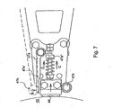
- Fig. 7 shows the action of the lever mechanism in detail, with the uncoupled state indicated by dashed lines.
- the projecting activation bearing 47b of a colliding carrier moves a first part 47a' of the lever in the direction indicated by arrow B, and then the first part 47a' moves a second part of the lever 47a'' in the direction indicated by arrow C, with the result that the coupling means 44 connected to this second part 47a" is uncoupled from the drive member 43.
- a spring arranged on the lever part 47a" ensures that the coupling means 44 remain coupled against the drive member 43. These springs are compressed in the coupled, activated state.
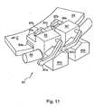
- Fig. 10 and Fig. 11 show side views of a fifth alternative embodiment of a conveyor device 60 according to the invention.
- the conveyor device 60 comprises a plurality of carriers 62, two 62 and 62' of which are shown, for carrying slaughtered poultry (not shown). Furthermore, the device comprises a guide 65 along which the carriers 62 can move in a conveying direction K and to which each of the carriers 62 is connected. An advancing drive member 63 for jointly driving the carriers 62 in the conveying direction K is parallel to the guide 65.
- Each carrier 62 has associated coupling means 64 for coupling the carrier 62 to the drive member 63.
- the coupling means 64 comprise a plate-like frictional body 64a and a projection 64b connected to it.
- the conveyor device 60 is also provided with decoupling means 67a, 67b and 67d for selectively decoupling one or more of the carriers 62.
- the carrier 62' is decoupled in Figures 10 and 11 .
- the actuating member 67a of the carrier 62' which catches up the carrier 62 comes into contact with the activation member 67d connected to carrier 62.
- the actuating member 67a is actuated and it moves the decoupling member 67b connected to it, resulting in a movement of the coupling means 64 in the upwards direction, indicated by the arrow L.
- the projection 64b moves through part 67c connected to the carrier.
Landscapes
- Engineering & Computer Science (AREA)
- Life Sciences & Earth Sciences (AREA)
- Wood Science & Technology (AREA)
- Zoology (AREA)
- Food Science & Technology (AREA)
- Mechanical Engineering (AREA)
- Processing Of Meat And Fish (AREA)
- Chain Conveyers (AREA)
Applications Claiming Priority (2)
| Application Number | Priority Date | Filing Date | Title |
|---|---|---|---|
| NL1028142A NL1028142C2 (nl) | 2005-01-28 | 2005-01-28 | Transportinrichting voor geslacht gevogelte. |
| PCT/NL2006/000017 WO2006080834A1 (en) | 2005-01-28 | 2006-01-12 | Conveyor device for slaughtered poultry |
Publications (2)
| Publication Number | Publication Date |
|---|---|
| EP1848282A1 EP1848282A1 (en) | 2007-10-31 |
| EP1848282B1 true EP1848282B1 (en) | 2009-02-25 |
Family
ID=34974995
Family Applications (1)
| Application Number | Title | Priority Date | Filing Date |
|---|---|---|---|
| EP06700354A Expired - Lifetime EP1848282B1 (en) | 2005-01-28 | 2006-01-12 | Conveyor device for slaughtered poultry |
Country Status (10)
| Country | Link |
|---|---|
| US (1) | US7837540B2 (enExample) |
| EP (1) | EP1848282B1 (enExample) |
| JP (1) | JP4966867B2 (enExample) |
| AT (1) | ATE423470T1 (enExample) |
| BR (1) | BRPI0606775B1 (enExample) |
| DE (1) | DE602006005336D1 (enExample) |
| DK (1) | DK1848282T3 (enExample) |
| ES (1) | ES2322616T3 (enExample) |
| NL (1) | NL1028142C2 (enExample) |
| WO (1) | WO2006080834A1 (enExample) |
Cited By (4)
| Publication number | Priority date | Publication date | Assignee | Title |
|---|---|---|---|---|
| NL2009198C2 (en) * | 2012-07-17 | 2014-01-20 | Meyn Food Proc Technology Bv | Processing apparatus for poultry comprising one or more transfer units. |
| US10159259B2 (en) | 2014-04-30 | 2018-12-25 | Linco Food Systems A/S | Method and an apparatus for arranging a bird in a position for being suspended from a shackle |
| WO2019203638A1 (en) | 2018-04-16 | 2019-10-24 | Meyn Food Processing Technology B.V. | Processing apparatus for poultry comprising one or more transfer units |
| US11889843B2 (en) | 2020-12-16 | 2024-02-06 | Marel Poultry B.V. | System and a method for processing poultry slaughter products |
Families Citing this family (29)
| Publication number | Priority date | Publication date | Assignee | Title |
|---|---|---|---|---|
| NL2000159C2 (nl) * | 2006-07-24 | 2008-01-25 | Stork Pmt | Inrichting, werkwijze en productielijn voor het conditioneren van geslacht pluimvee. |
| FR2933681B1 (fr) * | 2008-07-10 | 2011-04-29 | Thomas Cocirta | Dispositif de deplacement et positionnement des containers par chariots independants et re-circulants |
| ES2342810B1 (es) | 2008-09-10 | 2011-07-05 | Pere Poch Marti | Abrebocas perfeccionado para la introduccion de mascarillas laringeasy otros dispositivos medicos a traves de la cavidad oral. |
| DE202009013829U1 (de) * | 2009-10-12 | 2011-02-24 | Vemag Maschinenbau Gmbh | Aufhängevorrichtung zur Aufhängung von Würstchenketten |
| US8157625B2 (en) | 2010-01-26 | 2012-04-17 | Foodmate Bv | Method and apparatus for collecting meat from an animal part |
| US8632380B2 (en) | 2010-01-26 | 2014-01-21 | Foodmate B.V. | Method and apparatus for removing a sleeve of meat from an animal part having bone with knuckles on each of its opposite ends |
| NL2004573C2 (en) | 2010-04-19 | 2011-10-20 | Foodmate B V | Turning block alignment. |
| US8757354B2 (en) | 2010-04-19 | 2014-06-24 | Foodmate Bv | Turning block alignment |
| NL2004574C2 (en) | 2010-04-19 | 2011-10-20 | Foodmate B V | Rotatable article support for a conveyor. |
| NL2006075C2 (en) | 2011-01-26 | 2012-07-30 | Foodmate B V | Rotationally indexed article support for a conveyor system having an alignment station. |
| US8789684B2 (en) | 2010-04-19 | 2014-07-29 | Foodmate Bv | Rotatable article support for a conveyor |
| US8727839B2 (en) | 2011-01-21 | 2014-05-20 | Foodmate Bv | Poultry wing cutter for narrow pitch poultry lines |
| EP2667728B1 (en) | 2011-01-26 | 2015-07-29 | Foodmate B.V. | Method of deboning animal thighs for separating and collecting meat there from and apparatus for performing the method |
| US8882571B2 (en) | 2011-01-26 | 2014-11-11 | Foodmate Bv | Method of deboning animal thighs for separating and collecting meat therefrom and apparatus for performing the method |
| US8267241B2 (en) | 2011-01-26 | 2012-09-18 | Foodmate Bv | Rotationally indexed article support for a conveyor system having an alignment station |
| US8430728B2 (en) | 2011-02-14 | 2013-04-30 | Foodmate Bv | Special cut poultry wing cutter |
| NL2007329C2 (en) | 2011-09-01 | 2013-03-04 | Marel Stork Poultry Proc Bv | Method and installation for processing slaughtered poultry. |
| NL2009033C2 (en) | 2012-06-19 | 2013-12-23 | Foodmate B V | Weighing method and apparatus. |
| NL2009718C2 (en) | 2012-10-29 | 2014-05-01 | Foodmate B V | Method of mechanically removing skin from animal parts. |
| US8808068B2 (en) | 2012-10-29 | 2014-08-19 | Foodmate Bv | Method of and system for automatically removing meat from an animal extremity |
| US9078453B2 (en) | 2013-11-01 | 2015-07-14 | Foodmate B.V. | Method and system for automatically deboning poultry breast caps containing meat and a skeletal structure to obtain breast fillets therefrom |
| US8961274B1 (en) | 2013-12-18 | 2015-02-24 | Foodmate Bv | Selective tendon cutter and method |
| NL2013532B1 (nl) * | 2014-09-26 | 2016-09-29 | Marel Stork Poultry Proc Bv | Inrichting en werkwijze voor het verwerken van slachtdieren en/of delen daarvan. |
| EP3501286B1 (en) | 2017-12-22 | 2022-10-26 | Radie B.V. | Dough processing device, for use on a dough line |
| NL2020773B1 (en) * | 2018-04-16 | 2019-10-23 | Meyn Food Processing Tech Bv | Processing apparatus for poultry comprising one or more transfer units |
| JP6985562B2 (ja) * | 2018-09-03 | 2021-12-22 | エフピイアイ・フード・プロセッシング・イノヴェーション・ゲーエムベーハー・ウント・コンパニ・カーゲー | 食鳥を搬送する設備及び方法 |
| US20200170225A1 (en) * | 2018-11-30 | 2020-06-04 | Adelfo Andres Anguiano Jaimes | Chicken unloader |
| NL2022680B1 (en) | 2019-03-06 | 2020-09-17 | Marel Poultry B V | A poultry transfer mechanism |
| DK3729968T3 (da) | 2019-04-25 | 2022-03-28 | Nordischer Maschinenbau | Transportindretning til at transportere rensede fjerkrækroppe eller dele deraf |
Family Cites Families (13)
| Publication number | Priority date | Publication date | Assignee | Title |
|---|---|---|---|---|
| NL6511938A (enExample) | 1965-09-14 | 1967-03-15 | ||
| US3643293A (en) * | 1970-10-13 | 1972-02-22 | Pillsbury Co | Poultry transfer apparatus and method |
| JPS5415428Y2 (enExample) * | 1974-04-16 | 1979-06-21 | ||
| US3944078A (en) | 1974-08-27 | 1976-03-16 | W. F. Altenpohl, Inc. (Entire) | Counter controlled product conveyor distribution system |
| NL172295C (nl) | 1974-09-10 | 1985-10-16 | Stork Brabant Bv | Inrichting voor het overbrengen van geslacht gevogelte van een eerste naar een tweede transportbaan. |
| US4178659A (en) | 1977-10-31 | 1979-12-18 | Stork Gamco, Inc. | Transfer apparatus for poultry processing conveyor |
| JPS58137331A (ja) * | 1982-02-10 | 1983-08-15 | Nec Corp | インバ−タ回路 |
| NL8400447A (nl) * | 1984-02-10 | 1985-09-02 | Stork Pmt | Inrichting voor het overbrengen van geslacht gevogelte. |
| DE3445678A1 (de) | 1984-12-14 | 1986-06-19 | W. Schlafhorst & Co, 4050 Mönchengladbach | Vorrichtung zum konstanthalten der anzahl der zwischen einer spinnmaschine und einer spulmaschine in einem kreislauf befindlichen spulenhuelsen |
| WO1986006587A1 (en) | 1985-05-06 | 1986-11-20 | Golden Poultry Farming Industries Limited | The processing of poultry |
| JPH07110689B2 (ja) * | 1986-06-05 | 1995-11-29 | 共同印刷株式会社 | 物品区分け装置 |
| NL8602287A (nl) * | 1986-09-10 | 1988-04-05 | Stork Pmt | Inrichting voor het selectief overbrengen van aan een transportbaan aangevoerd geslacht gevogelte naar een of meer afvoerstations onder besturing van tenminste een langs de afvoerbaan aangebracht classificatiestation. |
| US5453045A (en) * | 1993-01-21 | 1995-09-26 | Systemate Holland, B.V. | System for transferring birds from one conveyor system to another with intermediate accumulator |
-
2005
- 2005-01-28 NL NL1028142A patent/NL1028142C2/nl not_active IP Right Cessation
-
2006
- 2006-01-12 ES ES06700354T patent/ES2322616T3/es not_active Expired - Lifetime
- 2006-01-12 DK DK06700354T patent/DK1848282T3/da active
- 2006-01-12 DE DE602006005336T patent/DE602006005336D1/de not_active Expired - Lifetime
- 2006-01-12 US US11/883,230 patent/US7837540B2/en active Active
- 2006-01-12 AT AT06700354T patent/ATE423470T1/de not_active IP Right Cessation
- 2006-01-12 JP JP2007553054A patent/JP4966867B2/ja not_active Expired - Lifetime
- 2006-01-12 BR BRPI0606775-1A patent/BRPI0606775B1/pt not_active IP Right Cessation
- 2006-01-12 WO PCT/NL2006/000017 patent/WO2006080834A1/en not_active Ceased
- 2006-01-12 EP EP06700354A patent/EP1848282B1/en not_active Expired - Lifetime
Cited By (10)
| Publication number | Priority date | Publication date | Assignee | Title |
|---|---|---|---|---|
| NL2009198C2 (en) * | 2012-07-17 | 2014-01-20 | Meyn Food Proc Technology Bv | Processing apparatus for poultry comprising one or more transfer units. |
| EP2687101A1 (en) | 2012-07-17 | 2014-01-22 | Meyn Food Processing Technology B.V. | Processing apparatus for poultry comprising one or more transfer units |
| CN103535424A (zh) * | 2012-07-17 | 2014-01-29 | 迈恩食品加工技术私人有限责任公司 | 包括一个或多个传送单元的用于处理家禽尸块的加工机 |
| US8708785B2 (en) | 2012-07-17 | 2014-04-29 | Meyn Food Processing Technology B.V. | Poultry processing apparatus having one or more transfer units |
| US8986082B2 (en) | 2012-07-17 | 2015-03-24 | Meyn Food Processing Technology B.V. | Poultry processing apparatus having one or more transfer units |
| EP2687101B1 (en) | 2012-07-17 | 2015-06-10 | Meyn Food Processing Technology B.V. | Processing apparatus for poultry comprising one or more transfer units |
| CN103535424B (zh) * | 2012-07-17 | 2016-07-06 | 迈恩食品加工技术私人有限责任公司 | 包括一个或多个传送单元的用于处理家禽尸块的加工机 |
| US10159259B2 (en) | 2014-04-30 | 2018-12-25 | Linco Food Systems A/S | Method and an apparatus for arranging a bird in a position for being suspended from a shackle |
| WO2019203638A1 (en) | 2018-04-16 | 2019-10-24 | Meyn Food Processing Technology B.V. | Processing apparatus for poultry comprising one or more transfer units |
| US11889843B2 (en) | 2020-12-16 | 2024-02-06 | Marel Poultry B.V. | System and a method for processing poultry slaughter products |
Also Published As
| Publication number | Publication date |
|---|---|
| NL1028142C2 (nl) | 2006-07-31 |
| ES2322616T3 (es) | 2009-06-23 |
| JP4966867B2 (ja) | 2012-07-04 |
| JP2008528026A (ja) | 2008-07-31 |
| WO2006080834A1 (en) | 2006-08-03 |
| BRPI0606775B1 (pt) | 2014-02-04 |
| BRPI0606775A2 (pt) | 2010-02-09 |
| EP1848282A1 (en) | 2007-10-31 |
| DE602006005336D1 (de) | 2009-04-09 |
| US20080125025A1 (en) | 2008-05-29 |
| ATE423470T1 (de) | 2009-03-15 |
| DK1848282T3 (da) | 2009-06-02 |
| US7837540B2 (en) | 2010-11-23 |
Similar Documents
| Publication | Publication Date | Title |
|---|---|---|
| EP1848282B1 (en) | Conveyor device for slaughtered poultry | |
| US4892186A (en) | Clock conveyor provided with a plurality of entrainment members | |
| US4088220A (en) | Endless conveyors for the horizontal rotary conveyance of objects | |
| US3960262A (en) | Accumulating conveyor | |
| GB1304917A (enExample) | ||
| JPH03147737A (ja) | 連続ソーセージケーシングに充填されたソーセージを搬送する装置 | |
| AU748498B2 (en) | Magnetically powered conveyor system and method | |
| CN111712449B (zh) | 积聚式输送机系统 | |
| GB1413385A (en) | Apparatus for the automatic feeding of articles to packaging machines | |
| US4428299A (en) | Arrangement for transferring carriers at power line discontinuous portion of power-and-free trolley conveyor | |
| DK97389A (da) | Akkumuleringstransportoer | |
| GB1230918A (enExample) | ||
| JPH08216874A (ja) | トロリーコンベヤのキャリヤの逆走防止装置 | |
| RU2194002C2 (ru) | Устройство для изменения положения предметов, транспортируемых в каскадном потоке | |
| ES391811A1 (es) | Unos perfeccionamientos en los transportadores mecanicos. | |
| JP2008143666A (ja) | 傾斜又は垂直コンベアの逸走防止装置 | |
| CN208647879U (zh) | 一种非拉紧式输送机构的驱动装置 | |
| GB2331974A (en) | Hanger conveyor system | |
| SU685571A1 (ru) | Гравитационный конвейер | |
| SU755701A1 (ru) | Конвейер 1 | |
| SU918198A1 (ru) | Тележечный конвейер | |
| SU1368233A1 (ru) | Тележечный конвейер | |
| JPS5827875Y2 (ja) | 傾斜コンベヤの逸走防止装置 | |
| GB1112105A (en) | Improvements in conveyor systems incorporating carrier transfer between main and branch lines | |
| US20030173270A1 (en) | Device for transporting and sorting unit loads |
Legal Events
| Date | Code | Title | Description |
|---|---|---|---|
| PUAI | Public reference made under article 153(3) epc to a published international application that has entered the european phase |
Free format text: ORIGINAL CODE: 0009012 |
|
| 17P | Request for examination filed |
Effective date: 20070821 |
|
| AK | Designated contracting states |
Kind code of ref document: A1 Designated state(s): AT BE BG CH CY CZ DE DK EE ES FI FR GB GR HU IE IS IT LI LT LU LV MC NL PL PT RO SE SI SK TR |
|
| 17Q | First examination report despatched |
Effective date: 20080117 |
|
| DAX | Request for extension of the european patent (deleted) | ||
| GRAP | Despatch of communication of intention to grant a patent |
Free format text: ORIGINAL CODE: EPIDOSNIGR1 |
|
| GRAS | Grant fee paid |
Free format text: ORIGINAL CODE: EPIDOSNIGR3 |
|
| GRAA | (expected) grant |
Free format text: ORIGINAL CODE: 0009210 |
|
| AK | Designated contracting states |
Kind code of ref document: B1 Designated state(s): AT BE BG CH CY CZ DE DK EE ES FI FR GB GR HU IE IS IT LI LT LU LV MC NL PL PT RO SE SI SK TR |
|
| REG | Reference to a national code |
Ref country code: GB Ref legal event code: FG4D |
|
| REG | Reference to a national code |
Ref country code: CH Ref legal event code: EP |
|
| REG | Reference to a national code |
Ref country code: IE Ref legal event code: FG4D |
|
| REF | Corresponds to: |
Ref document number: 602006005336 Country of ref document: DE Date of ref document: 20090409 Kind code of ref document: P |
|
| REG | Reference to a national code |
Ref country code: DE Ref legal event code: R096 Ref document number: 602006005336 Country of ref document: DE Effective date: 20090409 |
|
| REG | Reference to a national code |
Ref country code: DK Ref legal event code: T3 |
|
| REG | Reference to a national code |
Ref country code: ES Ref legal event code: FG2A Ref document number: 2322616 Country of ref document: ES Kind code of ref document: T3 |
|
| PG25 | Lapsed in a contracting state [announced via postgrant information from national office to epo] |
Ref country code: FI Free format text: LAPSE BECAUSE OF FAILURE TO SUBMIT A TRANSLATION OF THE DESCRIPTION OR TO PAY THE FEE WITHIN THE PRESCRIBED TIME-LIMIT Effective date: 20090225 Ref country code: LT Free format text: LAPSE BECAUSE OF FAILURE TO SUBMIT A TRANSLATION OF THE DESCRIPTION OR TO PAY THE FEE WITHIN THE PRESCRIBED TIME-LIMIT Effective date: 20090225 Ref country code: SI Free format text: LAPSE BECAUSE OF FAILURE TO SUBMIT A TRANSLATION OF THE DESCRIPTION OR TO PAY THE FEE WITHIN THE PRESCRIBED TIME-LIMIT Effective date: 20090225 |
|
| PG25 | Lapsed in a contracting state [announced via postgrant information from national office to epo] |
Ref country code: SE Free format text: LAPSE BECAUSE OF FAILURE TO SUBMIT A TRANSLATION OF THE DESCRIPTION OR TO PAY THE FEE WITHIN THE PRESCRIBED TIME-LIMIT Effective date: 20090525 Ref country code: PL Free format text: LAPSE BECAUSE OF FAILURE TO SUBMIT A TRANSLATION OF THE DESCRIPTION OR TO PAY THE FEE WITHIN THE PRESCRIBED TIME-LIMIT Effective date: 20090225 Ref country code: AT Free format text: LAPSE BECAUSE OF FAILURE TO SUBMIT A TRANSLATION OF THE DESCRIPTION OR TO PAY THE FEE WITHIN THE PRESCRIBED TIME-LIMIT Effective date: 20090225 Ref country code: IS Free format text: LAPSE BECAUSE OF FAILURE TO SUBMIT A TRANSLATION OF THE DESCRIPTION OR TO PAY THE FEE WITHIN THE PRESCRIBED TIME-LIMIT Effective date: 20090625 Ref country code: LV Free format text: LAPSE BECAUSE OF FAILURE TO SUBMIT A TRANSLATION OF THE DESCRIPTION OR TO PAY THE FEE WITHIN THE PRESCRIBED TIME-LIMIT Effective date: 20090225 |
|
| PG25 | Lapsed in a contracting state [announced via postgrant information from national office to epo] |
Ref country code: BE Free format text: LAPSE BECAUSE OF FAILURE TO SUBMIT A TRANSLATION OF THE DESCRIPTION OR TO PAY THE FEE WITHIN THE PRESCRIBED TIME-LIMIT Effective date: 20090225 |
|
| PG25 | Lapsed in a contracting state [announced via postgrant information from national office to epo] |
Ref country code: EE Free format text: LAPSE BECAUSE OF FAILURE TO SUBMIT A TRANSLATION OF THE DESCRIPTION OR TO PAY THE FEE WITHIN THE PRESCRIBED TIME-LIMIT Effective date: 20090225 Ref country code: CZ Free format text: LAPSE BECAUSE OF FAILURE TO SUBMIT A TRANSLATION OF THE DESCRIPTION OR TO PAY THE FEE WITHIN THE PRESCRIBED TIME-LIMIT Effective date: 20090225 Ref country code: PT Free format text: LAPSE BECAUSE OF FAILURE TO SUBMIT A TRANSLATION OF THE DESCRIPTION OR TO PAY THE FEE WITHIN THE PRESCRIBED TIME-LIMIT Effective date: 20090812 |
|
| PG25 | Lapsed in a contracting state [announced via postgrant information from national office to epo] |
Ref country code: RO Free format text: LAPSE BECAUSE OF FAILURE TO SUBMIT A TRANSLATION OF THE DESCRIPTION OR TO PAY THE FEE WITHIN THE PRESCRIBED TIME-LIMIT Effective date: 20090225 Ref country code: SK Free format text: LAPSE BECAUSE OF FAILURE TO SUBMIT A TRANSLATION OF THE DESCRIPTION OR TO PAY THE FEE WITHIN THE PRESCRIBED TIME-LIMIT Effective date: 20090225 |
|
| PLBE | No opposition filed within time limit |
Free format text: ORIGINAL CODE: 0009261 |
|
| STAA | Information on the status of an ep patent application or granted ep patent |
Free format text: STATUS: NO OPPOSITION FILED WITHIN TIME LIMIT |
|
| PG25 | Lapsed in a contracting state [announced via postgrant information from national office to epo] |
Ref country code: BG Free format text: LAPSE BECAUSE OF FAILURE TO SUBMIT A TRANSLATION OF THE DESCRIPTION OR TO PAY THE FEE WITHIN THE PRESCRIBED TIME-LIMIT Effective date: 20090525 |
|
| 26N | No opposition filed |
Effective date: 20091126 |
|
| REG | Reference to a national code |
Ref country code: DE Ref legal event code: R097 Ref document number: 602006005336 Country of ref document: DE Effective date: 20091126 |
|
| PGFP | Annual fee paid to national office [announced via postgrant information from national office to epo] |
Ref country code: IT Payment date: 20100127 Year of fee payment: 5 |
|
| PG25 | Lapsed in a contracting state [announced via postgrant information from national office to epo] |
Ref country code: MC Free format text: LAPSE BECAUSE OF NON-PAYMENT OF DUE FEES Effective date: 20100131 |
|
| REG | Reference to a national code |
Ref country code: CH Ref legal event code: PL |
|
| PG25 | Lapsed in a contracting state [announced via postgrant information from national office to epo] |
Ref country code: LI Free format text: LAPSE BECAUSE OF NON-PAYMENT OF DUE FEES Effective date: 20100131 Ref country code: CH Free format text: LAPSE BECAUSE OF NON-PAYMENT OF DUE FEES Effective date: 20100131 Ref country code: GR Free format text: LAPSE BECAUSE OF FAILURE TO SUBMIT A TRANSLATION OF THE DESCRIPTION OR TO PAY THE FEE WITHIN THE PRESCRIBED TIME-LIMIT Effective date: 20090526 |
|
| PG25 | Lapsed in a contracting state [announced via postgrant information from national office to epo] |
Ref country code: IE Free format text: LAPSE BECAUSE OF NON-PAYMENT OF DUE FEES Effective date: 20100112 |
|
| PG25 | Lapsed in a contracting state [announced via postgrant information from national office to epo] |
Ref country code: IT Free format text: LAPSE BECAUSE OF NON-PAYMENT OF DUE FEES Effective date: 20110112 |
|
| PG25 | Lapsed in a contracting state [announced via postgrant information from national office to epo] |
Ref country code: CY Free format text: LAPSE BECAUSE OF FAILURE TO SUBMIT A TRANSLATION OF THE DESCRIPTION OR TO PAY THE FEE WITHIN THE PRESCRIBED TIME-LIMIT Effective date: 20090225 |
|
| PG25 | Lapsed in a contracting state [announced via postgrant information from national office to epo] |
Ref country code: LU Free format text: LAPSE BECAUSE OF NON-PAYMENT OF DUE FEES Effective date: 20100112 Ref country code: HU Free format text: LAPSE BECAUSE OF FAILURE TO SUBMIT A TRANSLATION OF THE DESCRIPTION OR TO PAY THE FEE WITHIN THE PRESCRIBED TIME-LIMIT Effective date: 20090826 |
|
| PG25 | Lapsed in a contracting state [announced via postgrant information from national office to epo] |
Ref country code: TR Free format text: LAPSE BECAUSE OF FAILURE TO SUBMIT A TRANSLATION OF THE DESCRIPTION OR TO PAY THE FEE WITHIN THE PRESCRIBED TIME-LIMIT Effective date: 20090225 |
|
| REG | Reference to a national code |
Ref country code: FR Ref legal event code: PLFP Year of fee payment: 11 |
|
| REG | Reference to a national code |
Ref country code: FR Ref legal event code: PLFP Year of fee payment: 12 |
|
| REG | Reference to a national code |
Ref country code: FR Ref legal event code: PLFP Year of fee payment: 13 |
|
| PGFP | Annual fee paid to national office [announced via postgrant information from national office to epo] |
Ref country code: ES Payment date: 20210201 Year of fee payment: 16 |
|
| REG | Reference to a national code |
Ref country code: ES Ref legal event code: FD2A Effective date: 20230227 |
|
| PG25 | Lapsed in a contracting state [announced via postgrant information from national office to epo] |
Ref country code: ES Free format text: LAPSE BECAUSE OF NON-PAYMENT OF DUE FEES Effective date: 20220113 |
|
| P01 | Opt-out of the competence of the unified patent court (upc) registered |
Effective date: 20230514 |
|
| PGFP | Annual fee paid to national office [announced via postgrant information from national office to epo] |
Ref country code: DK Payment date: 20241218 Year of fee payment: 20 |
|
| PGFP | Annual fee paid to national office [announced via postgrant information from national office to epo] |
Ref country code: NL Payment date: 20241219 Year of fee payment: 20 |
|
| PGFP | Annual fee paid to national office [announced via postgrant information from national office to epo] |
Ref country code: GB Payment date: 20241219 Year of fee payment: 20 |
|
| PGFP | Annual fee paid to national office [announced via postgrant information from national office to epo] |
Ref country code: FR Payment date: 20241219 Year of fee payment: 20 |
|
| PGFP | Annual fee paid to national office [announced via postgrant information from national office to epo] |
Ref country code: DE Payment date: 20241218 Year of fee payment: 20 |
|
| REG | Reference to a national code |
Ref country code: DE Ref legal event code: R071 Ref document number: 602006005336 Country of ref document: DE |
|
| REG | Reference to a national code |
Ref country code: NL Ref legal event code: MK Effective date: 20260111 |
|
| REG | Reference to a national code |
Ref country code: DK Ref legal event code: EUP Expiry date: 20260112 |
|
| REG | Reference to a national code |
Ref country code: GB Ref legal event code: PE20 Expiry date: 20260111 |