EP1847763B1 - Mehrseitige Beleuchtungsanordnung mit Entblendung - Google Patents
Mehrseitige Beleuchtungsanordnung mit Entblendung Download PDFInfo
- Publication number
- EP1847763B1 EP1847763B1 EP07104538A EP07104538A EP1847763B1 EP 1847763 B1 EP1847763 B1 EP 1847763B1 EP 07104538 A EP07104538 A EP 07104538A EP 07104538 A EP07104538 A EP 07104538A EP 1847763 B1 EP1847763 B1 EP 1847763B1
- Authority
- EP
- European Patent Office
- Prior art keywords
- housing
- assembly according
- lighting assembly
- openings
- lighting
- Prior art date
- Legal status (The legal status is an assumption and is not a legal conclusion. Google has not performed a legal analysis and makes no representation as to the accuracy of the status listed.)
- Not-in-force
Links
- 230000004313 glare Effects 0.000 title description 6
- 238000005286 illumination Methods 0.000 title description 4
- 230000005855 radiation Effects 0.000 claims abstract description 17
- 239000011521 glass Substances 0.000 claims description 7
- 238000001228 spectrum Methods 0.000 claims description 6
- NIXOWILDQLNWCW-UHFFFAOYSA-N acrylic acid group Chemical group C(C=C)(=O)O NIXOWILDQLNWCW-UHFFFAOYSA-N 0.000 claims description 4
- 239000000463 material Substances 0.000 claims description 4
- 239000004033 plastic Substances 0.000 claims description 2
- 239000004417 polycarbonate Substances 0.000 claims description 2
- 229920000515 polycarbonate Polymers 0.000 claims description 2
- 230000009970 fire resistant effect Effects 0.000 claims 1
- 230000006378 damage Effects 0.000 description 3
- 208000027418 Wounds and injury Diseases 0.000 description 2
- 238000011109 contamination Methods 0.000 description 2
- 208000014674 injury Diseases 0.000 description 2
- 239000002184 metal Substances 0.000 description 2
- 230000003595 spectral effect Effects 0.000 description 2
- 239000012780 transparent material Substances 0.000 description 2
- 240000006829 Ficus sundaica Species 0.000 description 1
- 230000000712 assembly Effects 0.000 description 1
- 238000000429 assembly Methods 0.000 description 1
- 238000005266 casting Methods 0.000 description 1
- 239000012141 concentrate Substances 0.000 description 1
- 230000001419 dependent effect Effects 0.000 description 1
- 238000009826 distribution Methods 0.000 description 1
- 239000000428 dust Substances 0.000 description 1
- 230000003670 easy-to-clean Effects 0.000 description 1
- 230000000694 effects Effects 0.000 description 1
- 230000002349 favourable effect Effects 0.000 description 1
- 239000003063 flame retardant Substances 0.000 description 1
- 239000011888 foil Substances 0.000 description 1
- 239000012535 impurity Substances 0.000 description 1
- 238000007689 inspection Methods 0.000 description 1
- 238000012423 maintenance Methods 0.000 description 1
- 238000004519 manufacturing process Methods 0.000 description 1
- 230000013011 mating Effects 0.000 description 1
- 239000011022 opal Substances 0.000 description 1
- 230000008447 perception Effects 0.000 description 1
- 238000003825 pressing Methods 0.000 description 1
- 239000000725 suspension Substances 0.000 description 1
Images




Classifications
-
- F—MECHANICAL ENGINEERING; LIGHTING; HEATING; WEAPONS; BLASTING
- F21—LIGHTING
- F21V—FUNCTIONAL FEATURES OR DETAILS OF LIGHTING DEVICES OR SYSTEMS THEREOF; STRUCTURAL COMBINATIONS OF LIGHTING DEVICES WITH OTHER ARTICLES, NOT OTHERWISE PROVIDED FOR
- F21V5/00—Refractors for light sources
- F21V5/002—Refractors for light sources using microoptical elements for redirecting or diffusing light
-
- F—MECHANICAL ENGINEERING; LIGHTING; HEATING; WEAPONS; BLASTING
- F21—LIGHTING
- F21V—FUNCTIONAL FEATURES OR DETAILS OF LIGHTING DEVICES OR SYSTEMS THEREOF; STRUCTURAL COMBINATIONS OF LIGHTING DEVICES WITH OTHER ARTICLES, NOT OTHERWISE PROVIDED FOR
- F21V21/00—Supporting, suspending, or attaching arrangements for lighting devices; Hand grips
- F21V21/005—Supporting, suspending, or attaching arrangements for lighting devices; Hand grips for several lighting devices in an end-to-end arrangement, i.e. light tracks
-
- F—MECHANICAL ENGINEERING; LIGHTING; HEATING; WEAPONS; BLASTING
- F21—LIGHTING
- F21V—FUNCTIONAL FEATURES OR DETAILS OF LIGHTING DEVICES OR SYSTEMS THEREOF; STRUCTURAL COMBINATIONS OF LIGHTING DEVICES WITH OTHER ARTICLES, NOT OTHERWISE PROVIDED FOR
- F21V3/00—Globes; Bowls; Cover glasses
- F21V3/04—Globes; Bowls; Cover glasses characterised by materials, surface treatments or coatings
-
- F—MECHANICAL ENGINEERING; LIGHTING; HEATING; WEAPONS; BLASTING
- F21—LIGHTING
- F21V—FUNCTIONAL FEATURES OR DETAILS OF LIGHTING DEVICES OR SYSTEMS THEREOF; STRUCTURAL COMBINATIONS OF LIGHTING DEVICES WITH OTHER ARTICLES, NOT OTHERWISE PROVIDED FOR
- F21V21/00—Supporting, suspending, or attaching arrangements for lighting devices; Hand grips
- F21V21/10—Pendants, arms, or standards; Fixing lighting devices to pendants, arms, or standards
- F21V21/112—Fixing lighting devices to pendants
-
- F—MECHANICAL ENGINEERING; LIGHTING; HEATING; WEAPONS; BLASTING
- F21—LIGHTING
- F21Y—INDEXING SCHEME ASSOCIATED WITH SUBCLASSES F21K, F21L, F21S and F21V, RELATING TO THE FORM OR THE KIND OF THE LIGHT SOURCES OR OF THE COLOUR OF THE LIGHT EMITTED
- F21Y2103/00—Elongate light sources, e.g. fluorescent tubes
Definitions
- the invention relates to a lighting arrangement comprising a housing, a lamp arranged in the housing, the radiation of which emerges from the housing through a plurality of housing openings, and means for deblasting this radiation, wherein at least one housing opening is arranged laterally and one housing opening is arranged downward.
- Interior lighting arrangements are usually either integrated into the wall or ceiling, provided thereon or suspended from the ceiling as pendant lights.
- the pendant lights usually have a cuboid, downwardly open housing.
- the suspension is attached to the top or ends of the housing.
- the light exits the downward opening from the housing.
- the opening is provided with fins.
- GB 713115 A is a lighting arrangement for an electric lantern disclosed.
- On one or both sides of the light source prismatic plates are arranged, which break the light by a division in the upper area downwards and reflect in the lower area.
- the down-facing lantern floor is either open or closed by a clear or transparent material.
- the lamp housing consists in principle of a cover plate on which the prismatic plates are clamped laterally by mounting bracket.
- the housing openings are closed with a transparent cover, which is profiled on the outside with a microstructure, the microstructure in turn is provided with a transparent, smooth cover, wherein the microstructure is designed blinding.
- the microstructure is designed in such a way that the angular range visible to persons is glare-free.
- the radiation not only goes down but into any desired angular range.
- the resulting glare is avoided by using a cover with a microstructure.
- smooth cover is provided on the profile. This additional cover is easy to clean and does not dirty easily. It is still manageable without risk of injury.
- the housing openings may extend along the majority of the side areas and downwards and the covers are arranged in frame parts. By using the profiled covers no glare can occur even with very large light exit openings.
- the housing may have a rectangular cross section, of which both sides and the lower portion form housing openings, which are covered by flat plates with profiled surface.
- the housing may also have a polygonal, oval or circular cross section.
- the housing can be tapered at the ends, the Gapuruse can be designed arcuate or graded stairs.
- the covers are made of pressed acrylic or glass.
- the cover may also be made of rolled material or foils. Made of pressed acrylic, the profile can be produced with the greatest precision.
- the covers can also consist of a fire-retardant plastic, in particular polycarbonate.
- the microstructures may be microprisms, in particular outwardly projecting microprisms.
- a microprism has dimensions in the range of a few tenths of a millimeter.
- pressed, linear or crossed structures are possible.
- the opening angle of the prisms or linear structures varies over the height of the opening.
- the laterally radiated radiation can be directed specifically in a preferred angular range.
- Other angular ranges are illuminated only slightly or not at all. In this way, on the one hand glare, on the other hand, an improved lighting in the desired direction.
- the housing comprises two end parts, which are connected to each other via frame parts, wherein the frame parts are held by parallel to the end portions extending, planar frames in addition in their position.
- the frame parts are profiled struts that have the same cross section over the entire length. This allows a cost-effective production.
- the frames may be inserted in slots or grooves provided in the struts perpendicular to their longitudinal axis.
- the light source to For example, a fluorescent lamp, can be passed through a recess in the frames.
- the end part has an opening into which connecting elements can be inserted.
- the fasteners can then be snapped or clamped. These fasteners can be variably selected.
- different connecting elements are used in the same housing. This creates a modular system that can be easily adapted to the requirements.
- the connecting elements can be connected to one another in an articulated manner and / or with fastening devices. Then several lights can be connected together.
- the connection angle is variable.
- a light source can have a spectrum with particularly high intensity in the short-wave spectral range and another light source can have a spectrum with particularly high intensity in the longer-wave spectral range. Then, for example, the light may be varied between a cold, rather blue spectrum corresponding to a high radiation temperature and a warm, rather red spectrum corresponding to a low radiation temperature.
- FIG.1 an exploded view of a modular lighting arrangement 10 is shown.
- Fig.2 is a cross section and in Figure 3 a longitudinal section through the arrangement shown.
- Figure 4 and 5 show the arrangement in assembled condition.
- like parts are given the same reference numerals.
- the lighting assembly comprises a housing 12.
- the housing 12 includes two parallel planar end portions 14 and 16.
- the end portions 14 and 16 are square and parallel.
- connecting struts 18, 20, 22 and 24 are inserted.
- the connecting struts are slightly longer than a fluorescent lamp of normal size. They connect the end parts 14 and 16.
- microprism plates described in more detail below. In Fig. 1 only one lateral microprism plate 32 is indicated.
- the upper opening 34 is covered by a metallic cover 36.
- a fluorescent lamp 40 On the bottom of a fluorescent lamp 40 is attached.
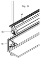
- the cover 36 is provided in the lateral areas 42 with a plurality of parallel slots through which light can also escape (see also Figure 19 ).
- the cover of the opaque material of the rest of the housing for example, chromed metal or the like.
- the top of the cover is screwed centrally with another, transparent, opal cover 44 with the rest of the housing. For this purpose, screws 43 are provided. This allows expansion of the cover in both directions when heated.
- At the ends of the cover control holes 45 are provided. The control holes 45 facilitate the removal of the cover, for example, during maintenance.
- Corresponding holes 47 are provided in the cover 36.
- the end parts 14 and 16 are provided with vertical, rectangular slots 46 (see also Figure 7 ). In the slots a cuboid projection 48 can be inserted, which sits on a connecting part 50.
- the connecting part has a vertical bore into which a tube 52 can be inserted. With the tube 52, the lamp is attached to a ceiling, for example. In the tube 52, the electrical leads for the supply of the light bulb are housed.
- the slot 46 has on the inside in the lower edge and a projecting, roof-shaped profile 49.
- the connecting part 50 has a corresponding profile 51, which in Fig. 8 is also recognizable.
- the connecting part 50 is inserted in the assembly in the slot 46, so that the profiles are positively against each other.
- a retractable screw is inserted through a corresponding threaded hole 53 into the profile 51 (FIG. Fig. 7 and 8th ) screwed. The screw fixed in this way the connecting part in its position.
- the struts 18, 20, 22 and 24 are provided with slots 60 into which ribs (support inserts) 54 made of metal or a transparent material are used. This is in cross section in Fig.2 and in the detail view in Fig. 6 again shown in more detail.
- the struts 18, 20, 22 and 24 are provided with circular projections 56 which extend in the direction of the illuminant.
- the projections 56 have a central bore 58.
- Slots 60 along the strut 18 serve as a receptacle for the frames 54.
- the frames 54 are flat and lie in a plane transverse to the connecting struts. They have four lugs 62, 64, 66 and 68 which extend in the direction of the connecting struts.
- Each of the flags is provided at its end with a bore which corresponds in the installed state with the bore 58 of the connecting strut 18.
- a wire or pipe threaded through the holes holds the frames and tie bars together.
- the frames 54 are rotatably mounted about axes 55. This facilitates the assembly.
- the covers 70 and the microprism plates 72 are ground on the outer edges 74. This is in Figure 6 shown.
- the connecting struts and the end pieces 14 and 16 have a corresponding profile. This facet cut is especially designed at the end pieces so that tolerances due to the different expansion coefficients of the materials is compensated. It is considered that the end pieces must have greater tolerances due to the greater extent in this direction.
- the circumferential facet grinding allows the positive engagement between the plates and the castings (end parts) or the struts and the end parts.
- the covers are held in position.
- the side housing openings and the downwardly oriented housing opening are covered in this way with glass plates 70.
- On the inside of the glass plates 70 each micro prism plates 72 are arranged.
- the microprism plates 72 are pressed from acrylic. They have a plurality of microprisms projecting outwardly towards the glass plate 70.
- the glass plate protects according to the projections from damage and contamination.
- a detail of such a micro prism plate 72 is shown in detail.
- the microprisms 71 are in the present embodiment of pyramidal projections, which are arranged directly next to each other.
- the deflection of a light beam is determined inter alia by the inclination angles ⁇ and ⁇ of the prism surfaces. It has been found that a ratio of the height of the microprisms to the overall height of the structure of 1: 3 is particularly favorable to produce.
- the microprisms are smaller than 2 mm and are produced with high quality by pressing.
- FIGS. 10 to 15 The effect of different angles on a laterally arranged micro prism plate is in the FIGS. 10 to 15 shown.
- Fig. 10 a section of a micro prism plate 73 is shown. The prisms have an opening angle 75 of 60 °.
- Fig. 10 is also shown a schematically illustrated illuminant 77.
- Figure 11 the course of the light rays 79 is shown. The light rays 79 are emitted from the microprism plate 73 Figure 10 distracted. It can be seen that in the configuration shown, within an observation angle 81 of 33.5 ° with respect to the horizontal 83, only very little radiation emerges, while the majority of the radiation concentrates in the steeply upwardly and downwardly directed areas. This avoids blinding observers in the more distant area.
- the room area below the luminaire eg a workplace, is well illuminated.
- the perception changes depending on the observer location.
- the observer entering a room sees little of the lamp and is not dazzled. The closer the observer gets to the lamp, the more it is illuminated.
- Fig. 12 and 13 an arrangement is shown in which the prism angle varies over the height of the illumination arrangement.
- a prism angle of 60 °.
- the prisms 89 are constructed asymmetrically. From the large angle 93, which is 98.4 °, only an angle 91 of 30 ° with respect to the horizontal 95 extends upward.
- the distribution of the asymmetrical prisms is 60 ° and 90 °.
- the associated beam path is in Fig. 13 shown. It can be seen that the middle region in Direction of the horizontal is completely debladed and practically no radiation in this angular range exits.
- Fig. 14 shows a micro prism plate 99 with unbalanced prisms. However, these are in contrast to the microprism plates after Fig. 10 to 13 inward, directed towards the bulb 101. In such an arrangement results in a course, as in Fig. 15 is shown. Again, there are areas 103 and 104 that are glare-free.
- the connecting struts 18, 20, 22 and 24 are provided on their end sides, each with an opening 78 in the longitudinal direction. In these openings 78 corresponding projections 76 are inserted on the inside of the end portions 14 and 16. This is best in Fig. 6 and 7 to see.
- the top cover rests on the case.
- the frames 66 are open at the top, as in Fig.2 is shown.
- the shape of the frames can be adapted to any cross-sectional shape. It is basically also changeable, which allows virtually any housing shapes.
- FIG. 7 is presented a first possibility of modular design.
- a connecting part 50 is inserted with a projection 48 in the manner already described.
- the connecting part 50 has a bore 80 into which a tube 52 (s. Fig.1 ) is introduced. With the tube 52, the light is fixed to the ceiling.
- FIG. 8 and Fig. 16-18 an alternative possibility of the modular design is shown.
- two connecting parts 82 and 84 of two different lighting elements (not shown) are fastened to the same tube 52.
- the tube 52 is inserted into a two-part sleeve 86.
- the sleeve protrudes through holes 88 and 90 in the connecting parts 82 and 84.
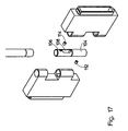
- the connecting parts 82 and 84 each have two recesses 92 and 94, in which engage the thus projecting parts 96 and 98 of the other connecting part. This is in Fig. 18 shown.
- the sleeve portions 104 and 106 of the sleeve 86 each have an opening 108 and 110, respectively (FIG. Figure 17 . Figure 18 ).
- a pin 112 or 114 is provided below the opening 110 or above the opening 108.
- each sleeve part 104 or 106 is fixed in its position relative to the connecting parts 82 and 84, respectively.
- the sleeve parts 104 and 106 are rotatable against each other.
- the opening 110 is always aligned in the direction of the connecting part 82.
- the opening 108 is always aligned in the direction of the connecting part 84. Both connecting parts are rotated against each other and the openings always remain aligned.
- the supply line for the lighting arrangement is placed. This is electrically connected to a three-part socket 116.
- the bushing 116 is in Fig. 19 shown in detail.
- the cover with the fluorescent tube has mating connectors 118. By simply plugging the cover so the electrical contact can be made.
- the sockets of the luminous means are provided in the cover, which is provided between two connecting struts. The socket is thus not arranged in the end parts.
- the supply line can be guided directly through the connecting part to the socket 116.
- linear, crossed and angled lamp assemblies can be created in a similar manner.
- the desired illumination profiles can be generated.
- certain angular ranges can be blended and the light can be directed to other areas.
- the opening angle 100 of the microprisms 102 is variable over the height of the opening. The opening angles are chosen so that the angular range from which can be seen in the light is blinding. The radiation is directed so that it falls into other angular ranges.
- the glass plates or the back of the profiled plate can be engraved with letters or screen-printed.
- the lighting arrangement is also suitable for attachment to the wall. Then the tubes 52 and possibly connecting parts are not required.
Landscapes
- Engineering & Computer Science (AREA)
- General Engineering & Computer Science (AREA)
- Non-Portable Lighting Devices Or Systems Thereof (AREA)
- Vessels And Coating Films For Discharge Lamps (AREA)
- Fastening Of Light Sources Or Lamp Holders (AREA)
Description
- Die Erfindung betrifft eine Beleuchtungsanordnung mit einem Gehäuse, einem in dem Gehäuse angeordneten Leuchtmittel, dessen Strahlung durch mehrere Gehäuseöffnungen aus dem Gehäuse austritt und Mitteln zum Entblenden dieser Strahlung, wobei wenigstens eine Gehäuseöffnung seitlich und eine Gehäuseöffnung nach unten angeordnet ist.
- Beleuchtungsanordnungen für den Innenbereich werden üblicherweise entweder in die Wand oder Decke integriert, daran vorgesehen oder hängen als Pendelleuchten von der Decke herab. Die Pendelleuchten haben meist ein quaderförmiges, nach unten offenes Gehäuse. Auf der Oberseite oder an den Enden des Gehäuses ist die Aufhängung befestigt.
- Bei den bekannten Pendelleuchten tritt das Licht aus der nach unten gerichteten Öffnung aus dem Gehäuse aus. Um direkte Einsicht auf das Leuchtmittel und dadurch verursachte Blendung zu vermeiden, wird die Öffnung mit Lamellen versehen.
- Es sind weiterhin Platten bekannt, die auf der Oberfläche mit Mikroprismen versehen sind. An diesen Mikroprismen wird das Licht abgelenkt. Bei Einsatz einer solchen Mikroprismenplatte in der Austrittsöffnung eines Leuchtengehäuses wird eine Blendung des Betrachters vermieden. Nachteilig bei diesen Platten ist es, daß diese leicht verschmutzen und verstauben. Verunreinigungen und Fingerabdrücke sind dauerhaft auf der Oberfläche sichtbar. Die Handhabung der scharfkantigen Platten kann zu Verletzungen führen.
- In der
GB 713115 A - Es ist Aufgabe der Erfindung, eine Beleuchtungsanordnung der eingangs genannten Art mit verbessertem Leuchtverhalten und leichter Handhabung zu schaffen.
- Erfindungsgemäß wird die Aufgabe gelöst die Merkmale des Anspruchs 1. Dabei sind die Gehäuseöffnungen mit einer transparenten Abdeckung verschlossen, die auf der Außenseite mit einer Mikrostruktur profiliert ist, die Mikrostruktur ihrerseits mit einer transparenten, glatten Abdeckung versehen ist, wobei die Mikrostruktur entblendend ausgebildet ist. Die Mikrostruktur ist derart ausgebildet, daß der für Personen sichtbare Winkelbereich entblendet ist.
- Bei dieser Anordnung tritt die Strahlung nicht nur nach unten, sondern in jeden gewünschten Winkelbereich aus. Die dadurch verursachte Blendung wird durch die Verwendung einer Abdeckung mit einer Mikrostruktur vermieden. Zur Vermeidung von Verschmutzung und erleichterten Handhabung dieser Abdeckung ist eine weitere, glatte Abdeckung auf dem Profil vorgesehen. Diese weitere Abdeckung lässt sich leicht reinigen und verschmutzt nicht so leicht. Sie ist weiterhin ohne Verletzungsgefahr handhabbar.
- Die Gehäuseöffnungen können sich entlang des überwiegenden Teils der Seitenbereiche und nach unten hin erstrecken und die Abdeckungen sind in Rahmenteilen angeordnet. Durch die Verwendung der profilierten Abdeckungen kann auch bei sehr großen Lichtaustrittsöffnungen keine Blendung erfolgen.
- Das Gehäuse kann einen rechteckigen Querschnitt aufweisen, von dem beide Seiten und der untere Abschnitt Gehäuseöffnungen bilden, die von ebenen Platten mit profilierter Oberfläche abgedeckt sind. Alternativ kann das Gehäuse aber auch einen mehreckigen, ovalen oder kreisförmigen Querschnitt aufweisen.
- Es ist weiterhin möglich Formen vorzusehen, deren Querschnitt über die Länge des Gehäuses veränderlich ist. So kann das Gehäuse sich an den Enden verjüngen, das Gahäuse kann bogenförmig ausgestaltet sein oder treppenartig abgestuft sein.
- Vorzugsweise sind die Abdeckungen aus gepresstem Acryl oder Glas. Alternativ kann die Abdeckung auch aus gewalztem Material oder Folien bestehen. Aus gepresstem Acryl ist das Profil mit der größten Präzision herstellbar. Die Abdeckungen können auch aus einem brandhemmenden Kunststoff, insbesondere aus Polycarbonat bestehen.
- Die Mikrostrukturen können Mikroprismen, insbesondere nach außen vorstehende Mikroprismen sein. Dabei hat ein Mikroprisma Abmessungen im Bereich von einigen Zehntel Millimeter. Alternativ sind auch gepresste, lineare oder gekreuzte Strukturen möglich. Vorzugsweise variiert der Öffnungswinkel der Prismen oder linearen Strukturen über die Höhe der Öffnung. Dann kann die seitlich abgestrahlte Strahlung gezielt in einen bevorzugten Winkelbereich gelenkt werden. Andere Winkelbereiche werden hingegen nur geringfügig oder gar nicht beleuchtet. Auf diese Weise erfolgt einerseits eine Entblendung, andererseits eine verbesserte Beleuchtung in der gewünschten Richtung.
- Das Gehäuse umfasst zwei Endteile, welche über Rahmenteile miteinander verbunden sind, wobei die Rahmenteile durch parallel zu den Endteilen verlaufende, plane Spanten zusätzlich in ihrer Lage gehalten werden. Die Rahmenteile sind profilierte Streben, die über die gesamte Länge den gleichen Querschnitt haben. Das ermöglicht eine kostengünstige Herstellung. Die Spanten können in Schlitzen oder Nuten, die in den Streben senkrecht zu deren Längsachse vorgesehen sind, eingeführt werden. Das Leuchtmittel, zum Beispiel eine Leuchtstofflampe, kann durch eine Aussparung in den Spantenn hindurch geführt werden.
- Vorzugsweise weist das Endteil eine Öffnung auf, in welche Verbindungselemente einsteckbar sind. Die Verbindungselemente können dann eingerastet oder eingeklemmt werden. Diese Verbindungselemente können variabel ausgewählt werden. Je nach Anwendung werden unterschiedliche Verbindungselemente in das gleiche Gehäuse eingesetzt. Auf diese Weise entsteht ein modulares System, dass leicht an die Anforderungen angepasst werden kann.
- In einer Ausgestaltung der Erfindung sind die Verbindungselemente gelenkig miteinander und/oder mit Befestigungsvorrichtungen verbindbar. Dann können mehrere Leuchten miteinander verbunden werden. Der Verbindungswinkel ist dabei variabel.
- Es können mehrere Leuchmittel mit unterschiedlichem Wellenlängenspektrum vorgesehen sein und Steuermittel, über welches die Strahlungsintensitäten der einzelnen Leuchtmittel einstellbar sind. Ein Leuchtmittel kann ein Spektrum mit besonders hoher Intensität im kurzwelligen Spektralbereich und ein weiteres Leuchtmittel kann ein Spektrum mit besonders hoher Intensität im längerwelligen Spektralbereich aufweisen. Dann kann das Licht zum Beispiel zwischen einem kalten, eher blauen Spektrum, entsprechend einer hohen Strahlungstemperatur, und einem warmen, eher roten Spektrum, entsprechend einer niedrigen Strahlungstemperatur, variiert werden.
- Ausgestaltungen der Erfindung sind Gegenstand der Unteransprüche. Ausführungsbeispiele sind nachstehend unter Bezugnahme auf die beigefügten Zeichnungen näher erläutert.
-
- Fig.1
- ist eine Explosionsdarstellung einer modular aufgebauten Beleuchtungsanordnung
- Fig.2
- ist ein Querschnitt durch die Beleuchtungsanordnung aus
Fig.1 - Fig.3
- ist ein Längsschnitt durch die Beleuchtungsanordnung aus
Fig.1 - Fig.4
- ist eine perspektivische Ansicht der geöffneten Beleuchtungsanordnung aus
Fig.1 - Fig.5
- ist eine perspektivische Ansicht der geöffneten Beleuchtungsanordnung aus
Fig.4 mit anderer Perspektive - Fig.6
- ist eine Detailansicht der Beleuchtungsanordnung aus
Fig.1 - Fig.7
- ist eine Detailansicht aus
Fig.1 mit einem Endteil und einem Verbindungsteil. - Fig.8
- ist ein Schnitt durch zwei Verbindungsteile.
- Fig.9
- ist eine vergrößerte, perspektivische Darstellung einer Mikroprismenplatte.
- Fig.10
- ist ein Querschnitt durch eine Mikroprismenplatte mit Prismen gleicher Größe
- Fig.11
- zeigt den Strahlenverlauf für die Anordnung aus
Fig.10 . - Fig.12
- ist ein Querschnitt durch eine Mikroprismenplatte mit Prismen mit unterschiedlichen Prismenwinkeln in verschiedenen Bereichen.
- Fig.13
- zeigt den Strahlenverlauf für die Anordnung aus
Fig.12 . - Fig. 14
- ist ein Querschnitt durch eine Mikroprismenplatte mit nach innen gerichteten Prismen.
- Fig.15
- zeigt den Strahlenverlauf für die Anordnung aus
Fig.14 . - Fig.16
- veranschaulicht ein Gelenk mit zwei Leuchtenelementen in Explosionsdarstellung.
- Fig.17
- veranschaulicht das Gelenk aus
Fig.16 aus einer anderen Perspektive. - Fig.18
- veranschaulicht ein Gelenk für mehrere Leuchtenelemente nach
Fig.16 in zusammengesetztem Zustand. - Fig.19
- ist eine Detaildarstellung der Beleuchtungsanordnung aus
Fig.1 mit einer elektrischen Steckverbindung. - Fig. 20
- ist eine Detaildarstellung analog zu
Fig.19 aus einer anderen Perspektive. - In
Fig.1 ist eine Explosionsdarstellung einer modular aufgebauten Beleuchtungsanordnung 10 dargestellt. InFig.2 ist ein Querschnitt und inFig.3 ein Längsschnitt durch die Anordnung dargestellt.Fig.4 und5 zeigen die Anordnung in zusammengebautem Zustand. In allen Figuren sind gleiche Teile mit gleichen Bezugszeichen versehen. - Die Beleuchtungsanordnung umfasst ein Gehäuse 12. Das Gehäuse 12 umfasst zwei parallele, plane Endteile 14 und 16. Die Endteile 14 und 16 sind quadratisch und parallel angeordnet. An den Ecken der Endteile 14 und 16 sind Verbindungsstreben 18, 20, 22 und 24 eingesteckt. Die Verbindungsstreben sind etwas länger als eine Leuchtstofflampe normierter Größe. Sie verbinden die Endteile 14 und 16.
- Die von den Endteilen 14 und 16 und den Verbindungsstreben 18, 20, 22 und 24 gebildeten seitlichen Öffnungen 26 und 28, sowie die nach unten gerichtete Öffnung 30 sind von nachstehend näher beschriebenen Mikroprismen-Platten abgedeckt. In
Fig. 1 ist lediglich eine seitliche Mikroprismenplatte 32 angedeutet. - Die obere Öffnung 34 ist von einer metallischen Abdeckung 36 abgedeckt. Diese bildet eine breite Nut entlang der gesamten Länge des Gehäuses, in welcher das Vorschaltgerät 38 und die Kabelzuführungen angeordnet sind. Auf der Unterseite ist eine Leuchtstofflampe 40 angebracht. Die Abdeckung 36 ist in den seitlichen Bereichen 42 mit einer Vielzahl paralleler Schlitze versehen, durch die ebenfalls Licht austreten kann (s. auch
Fig.19 ). Im übrigen ist die Abdeckung aus dem opakem Material des übrigen Gehäuses, zum Beispiel verchromtem Metall oder dergleichen. Die Oberseite der Abdeckung ist mit einer weiteren, transparenten, opalen Abdeckung 44 mit dem übrigen Gehäuse mittig verschraubt. Hierfür sind Schrauben 43 vorgesehen. Das erlaubt bei Erwärmung eine Ausdehnung der Abdeckung in beiden Richtungen. An den Enden der Abdeckung sind Bedienlöcher 45 vorgesehen. Die Bedienlöcher 45 erleichtern das Herausnehmen der Abdeckung z.B. bei Wartung. Korrespondierende Löcher 47 sind in der Abdeckung 36 vorgesehen. - Die Endteile 14 und 16 sind mit vertikalen, rechteckigen Schlitzen 46 versehen (s. auch
Fig.7 ). In die Schlitze ist ein quaderförmiger Vorsprung 48 einsteckbar, der auf einem Verbindungsteil 50 sitzt. Das Verbindungsteil weist eine vertikale Bohrung auf, in welche ein Rohr 52 einsteckbar ist. Mit dem Rohr 52 wird die Leuchte zum Beispiel an einer Decke befestigt. In dem Rohr 52 sind die elektrischen Zuleitungen für die Versorgung des Leuchtmittels untergebracht. - Der Schlitz 46 weist auf der Innenseite im unteren Rand und ein vorspringendes, dachförmiges Profil 49 auf. Das Verbindungsteil 50 weist ein korrespondierendes Profil 51 auf, das in
Fig. 8 ebenfalls erkennbar ist. Das Verbindungsteil 50 wird beim Zusammenbau in den Schlitz 46 eingesteckt, so daß die Profile formschlüssig aufeinander liegen. Eine versenkbare Schraube wird durch eine entsprechende Gewindebohrung 53 bis in das Profil 51 (Fig. 7 und8 ) geschraubt. Die Schraube fixiert auf diese Weise das Verbindungsteil in seiner Lage. - Da die Anordnung vergleichsweise lang ist, sind die Streben 18, 20, 22 und 24 mit Schlitzen 60 versehen, in welche Spanten (Stützeinsätze) 54 aus Metall oder einem transparenten Material eingesetzt sind. Dies ist im Querschnitt in
Fig.2 und in der Detailansicht inFig. 6 noch einmal genauer dargestellt. - Die Streben 18, 20, 22 und 24 sind mit kreisförmigen Vorsprüngen 56 versehen, die sich in die Richtung des Leuchtmittels erstrecken. Die Vorsprünge 56 weisen eine Mittenbohrung 58 auf. Schlitze 60 entlang der Strebe 18 dienen als Aufnahme für die Spanten 54. Die Spanten 54 sind plan und liegen in einer Ebene quer zu den Verbindungsstreben. Sie weisen vier Fahnen 62, 64, 66 und 68 auf, die sich in Richtung der Verbindungsstreben erstrecken. Jede der Fahnen ist an ihrem Ende mit einer Bohrung versehen, die in eingebautem Zustand mit der Bohrung 58 der Verbindungsstrebe 18 korrespondiert. Ein Draht oder ein Rohr, die durch die Bohrungen gefädelt wird, hält die Spanten und die Verbindungsstreben zusammen. Solange die Endkappen nicht aufgesetzt sind, sind die Spanten 54 um Achsen 55 drehbar gelagert. Das erleichtert die Montage.
- Die Abdeckungen 70 und die Mikroprismenplatten 72 sind an den außen liegenden Kanten 74 angeschliffen. Dies ist in
Fig.6 gezeigt. Die Verbindungsstreben und die Endstücke 14 und 16 haben ein korrespondierendes Profil. Dieser Facettenschliff ist insbesondere an den Endstücken so ausgelegt, dass Toleranzen aufgrund der unterschiedlichen Ausdehnungskoeffizienten der Materialien kompensiert wird. Dabei wird berücksichtigt, dass die Endstücke aufgrund der größeren Ausdehnung in dieser Richtung größere Toleranzen aufweisen müssen. Der umlaufende Facettenschliff ermöglicht den Formschluß zwischen den Platten und den Gußteilen (Endteilen) bzw. den Streben und den Endteilen. - Durch die Profile der Verbindungsstreben werden die Abdeckungen in ihrer Lage gehalten. Die seitlichen Gehäuseöffnungen und die nach unten ausgerichtete Gehäuseöffnung sind auf diese Weise mit Glasplatten 70 abgedeckt. Auf der Innenseite der Glasplatten 70 sind jeweils Mikroprismenplatten 72 angeordnet. Die Mikroprismenplatten 72 sind aus Acryl gepresst. Sie weisen eine Vielzahl von Mikroprismen auf, die nach außen zur Glasplatte 70 hin vorstehen. Die Glasplatte schützt entsprechend die Vorsprünge vor Beschädigung und Verschmutzung.
- In
Fig. 9 ist ein Ausschnitt einer solchen Mikroprismenplatte 72 im Detail dargestellt. Die Mikroprismen 71 bestehen im vorliegenden Ausführungsbeispiel aus pyramidenförmigen Vorsprüngen, die unmittelbar nebeneinander angeordnet sind. Die Ablenkung eines Lichtstrahls wird dabei unter anderem von den Neigungswinkeln α und β der Prismenflächen bestimmt. Es hat sich herausgestellt, daß ein Verhältnis der Höhe der Mikroprismen zur Gesamthöhe der Struktur von 1:3 besonders günstig herstellbar ist. Die Mikroprismen sind kleiner als 2 mm und werden mit hoher Qualität durch Pressen produziert. - Der Effekt unterschiedlicher Winkel an einer seitlich angeordneten Mikroprismenplatte ist in den
Figuren 10 bis 15 dargestellt. InFig. 10 ist ein Ausschnitt aus einer Mikroprismenplatte 73 dargestellt. Die Prismen haben einen Öffnungswinkel 75 von 60°. InFig. 10 ist ebenfalls ein schematisch dargestelltes Leuchtmittel 77 gezeigt. InFig.11 ist der Verlauf der Lichtstrahlen 79 dargestellt. Die Lichtstrahlen 79 werden an der Mikroprismenplatte 73 ausFig.10 abgelenkt. Man erkennt, daß bei der gezeigten Konfiguration innerhalb eines Beobachtungswinkels 81 von 33,5° gegenüber der Horizontalen 83 nur sehr wenig Strahlung austritt, während der überwiegende Teil der Strahlung sich in den steil nach unten und oben gerichteten Bereichen konzentriert. Auf diese Weise wird eine Blendung von Betrachtern im entfernteren Bereich vermieden. Der unterhalb der Leuchte befindliche Raumbereich, z.B. ein Arbeitsplatz wird hingegen gut beleuchtet. Mit einer solchen Beleuchtungsanordnung ändert sich also die Wahrnehmung in Abhängigkeit vom Beobachterstandort. Der in einen Raum eintretende Beobachter sieht nur wenig von der Lampe und wird nicht geblendet. Je näher der Beobachter an die Lampe herankommt, um so mehr wird er beleuchtet. - In
Fig. 12 und13 ist eine Anordnung gezeigt, bei der der Prismenwinkel über die Höhe der Beleuchtungsanordnung variiert. Wie bei dem Ausführungsbeispiel nachFig. 10 und11 ist im mittleren Bereich 83 der Mikroprismenplatte 85 ein Prismenwinkel von 60° vorgesehen. Im oberen Bereich 87 sind die Prismen 89 unsymmetrisch aufgebaut. Vom großen Winkel 93, der 98,4° beträgt, erstreckt sich nur ein Winkel 91 von 30° gegenüber der Horizontalen 95 nach oben. Im unteren Bereich 97 ist die Verteilung der unsymmetrischen Prismen 60° und 90°. Der zugehörige Strahlenverlauf ist inFig. 13 dargestellt. Man erkennt, daß der mittlere Bereich in Richtung der Horizontalen vollständig entblendet ist und praktisch keinerlei Strahlung in diesen Winkelbereich austritt. -
Fig. 14 zeigt eine Mikroprismenplatte 99 mit unsymmetrisch aufgebauten Prismen. Diese sind jedoch im Gegensatz zu den Mikroprismenplatten nachFig. 10 bis 13 nach innen, in Richtung auf das Leuchtmittel 101 gerichtet. Bei einer solchen Anordnung ergibt sich ein Verlauf, wie er inFig. 15 dargestellt ist. Auch hier gibt es Bereiche 103 und 104, die entblendet sind. - Die Verbindungsstreben 18, 20, 22 und 24 sind auf ihren Endseiten mit je einer Öffnung 78 in Längsrichtung versehen. In diese Öffnungen 78 werden korrespondierende Vorsprünge 76 auf der Innenseite der Endteile 14 und 16 gesteckt. Dies ist am besten in
Fig. 6 und7 zu sehen. - Die obere Abdeckung liegt auf dem Gehäuse auf. Zur Aufnahme der Leuchtstofflampe sind die Spanten 66 nach oben hin offen, wie es in
Fig.2 dargestellt ist. Die Form der Spanten kann an jede beliebige Querschnittsform angepasst werden. Sie ist grundsätzlich auch veränderlich, was quasi beliebige Gehäuseformen erlaubt. - In
Fig.7 ist eine erste Möglichkeit der modularen Bauweise dargestellt. In den Schlitz 46 des Endteils 14 wird ein Verbindungsteil 50 mit einem Vorsprung 48 auf bereits beschriebene Weise eingesteckt. Das Verbindungsteil 50 weist eine Bohrung 80 auf, in welche ein Rohr 52 (s.Fig.1 ) eingeführt wird. Mit dem Rohr 52 wird die Leuchte an der Decke befestigt. - In
Fig.8 undFig. 16-18 ist eine alternative Möglichkeit der modularen Bauweise dargestellt. Statt nur eines Verbindungsteils werden zwei Verbindungsteile 82 und 84 von zwei verschiedenen Leuchtenelementen (nicht dargestellt) an dem gleichen Rohr 52 befestigt. Zu diesem Zweck wird das Rohr 52 in eine zweiteilig Hülse 86 eingeführt. Die Hülse ragt durch Bohrungen 88 und 90 in den Verbindungsteilen 82 und 84. Die Verbindungsteile 82 und 84 weisen je zwei Ausnehmungen 92 und 94 auf, in welche die so vorstehenden Teile 96 und 98 des jeweils anderen Verbindungsteils eingreifen. Dies ist inFig. 18 dargestellt. - Die Hülsenteile 104 und 106 der Hülse 86 weisen jede eine Öffnung 108 bzw. 110 auf (
Fig.17 ,Fig.18 ). Unterhalb der Öffnung 110 bzw. oberhalb der Öffnung 108 ist ein Stift 112 bzw. 114 vorgesehen. Mit diesem Stift wird jedes Hülsenteil 104 bzw. 106 in seiner Lage gegenüber den Verbindungsteilen 82 bzw. 84 fixiert. Die Hülsenteile 104 und 106 sind gegeneinander verdrehbar. Dadurch ist die Öffnung 110 immer in Richtung des Verbindungsteils 82 ausgerichtet. Die Öffnung 108 ist immer in Richtung des Verbindungsteils 84 ausgerichtet. Beide Verbindungsteile sind gegeneinander verdrehbar und die Öffnungen bleiben immer ausgerichtet. Durch den in dem Rohr 52 vorgesehenen Hohlraum, die Hülse 86 und die Öffnungen wird die Zuleitung für die Beleuchtungsanordnung gelegt. Diese wird mit einer dreiteiligen Buchse 116 elektrisch leitend verbunden. Die Buchse 116 ist inFig. 19 im Detail dargestellt. Die Abdeckung mit der Leuchtstoffröhre weist passende Stecker 118 auf. Durch einfaches Aufstecken der Abdeckung kann so die elektrische Kontaktierung erfolgen. Die Fassungen des Leuchtmittels sind in der Abdeckung vorgesehen, die zwischen zwei Verbindungsstreben vorgesehen ist. Die Fassung ist somit nicht in den Endteilen angeordnet. - Bei einer Anordnung, bei der das Verbindungsteil nicht mit weiteren Verbindungsteilen verbunden ist, kann die Zuleitung direkt durch das Verbindungsteil zur Buchse 116 geführt werden.
- Mit den verschiedenen Verbindungsteilen können auf ähnliche Weise lineare, gekreuzte und gewinkelte Leuchtenanordnungen geschaffen werden.
- Mit der dargestellten Beleuchtungsanordnung lassen sich die gewünschten Beleuchtungsprofile erzeugen. Insbesondere können bestimmte Winkelbereiche entblendet werden und das Licht in andere Bereiche geleitet werden. Zu diesem Zweck ist der Öffnungswinkel 100 der Mikroprismen 102 über die Höhe der Öffnung variabel. Die Öffnungswinkel werden so gewählt, daß der Winkelbereich, aus dem in die Leuchte eingesehen werden kann entblendet wird. Die Strahlung wird so gelenkt, daß sie in andere Winkelbereiche fällt.
- Die Glasplatten oder die Rückseite der profilierten Platte können mit Schriftzeichen graviert oder mit Siebdruck versehen sein. Die Beleuchtungsanordnung eignet sich auch zum Anbringen an der Wand. Dann sind die Rohre 52 und ggf. Verbindungsteile nicht erforderlich.
Claims (11)
- Beleuchtungsanordnung (10) mit einem Gehäuse (12), einem in dem Gehäuse angeordneten Leuchtmittel (40), dessen Strahlung durch mehrere Gehäuseöffnungen (26, 28, 30) aus dem Gehäuse austritt und Mitteln (72) zum Entblenden dieser Strahlung, wobei wenigstens eine Gehäuseöffnung (26, 28) seitlich und eine Gehäuseöffnung (30) nach unten angeordnet ist und wobei die seitliche und die nach unten gerichtete Gehäuseöffnung jeweils mit einer transparenten Abdeckung (72) verschlossen ist, von denen wenigstens eine seitliche und die nach unten gerichtete Abdeckung auf der Außenseite mit einer Mikrostruktur (102) profiliert ist, die Mikrostruktur ihrerseits mit einer transparenten, glatten Abdeckung (70) versehen ist, wobei(a) die Mikrostruktur entblendend ausgebildet ist, so dass der für Personen sichtbare Winkelbereich entblendet ist, und(b) das Gehäuse von profilierten Verbindungsstreben und zwei Endteilen gebildet ist, wobei die Verbindungsstreben die Endteile derart miteinander verbinden, dass die Abdeckungen in dem Profil der Verbindungsstreben in ihrer Lage zwischen den Verbindungsstreben gehalten werden.
- Beleuchtungsanordnung nach Anspruch 1, dadurch gekennzeichnet, daß sich die Gehäuseöffnungen entlang des überwiegenden Teils der Seitenbereiche und nach unten hin erstrecken, und die Abdeckungen in einem oder mehreren von den Verbindungsstreben gebildeten Rahmenteilen angeordnet sind.
- Beleuchtungsanordnung nach Anspruch 2, dadurch gekennzeichnet, daß das Gehäuse einen rechteckigen Querschnitt aufweist, von dem beide Seiten und der untere Abschnitt Gehäuseöffnungen bilden, die von ebenen Platten mit profilierter Oberfläche (72) abgedeckt sind.
- Beleuchtungsanordnung nach einem der vorgehenden Ansprüche, dadurch gekennzeichnet, daß die Abdeckungen (72) aus gepresstem Acryl oder Glas sind.
- Beleuchtungsanordnung nach einem der Ansprüche 1 bis 3, dadurch gekennzeichnet, daß die Abdeckungen (70, 72) aus einem brandhemmenden Kunststoff, insbesondere Polycarbonat bestehen.
- Beleuchtungsanordnung nach einem der vorgehenden Ansprüche, dadurch gekennzeichnet, daß die Mikrostrukturen Mikroprismen (102) sind.
- Beleuchtungsanordnung nach Anspruch 3, dadurch gekennzeichnet, daß die Platten zur Abdeckung der seitlichen Gehäuseöffnungen eine Oberfläche mit einem Profil aufweisen, das aus nach außen vorstehenden Prismen oder linearen Lamellen besteht, wobei der Öffnungswinkel (100) der Prismen oder linearen Lamellen über die Höhe der Öffnung variiert.
- Beleuchtungsanordnung nach einem der vorgehenden Ansprüche, dadurch gekennzeichnet, daß die Endteile (14, 16) über von den Verbindungsstreben gebildete Rahmenteile (18, 20, 22, 24) miteinander verbunden sind, wobei die Rahmenteile durch parallel zu den Endteilen verlaufende, plane Spanten (54) zusätzlich in ihrer Lage gehalten werden.
- Beleuchtungsanordnung nach Anspruch 8, dadurch gekennzeichnet, daß das Endteil (14, 16) eine Öffnung (46) aufweist, in welche Verbindungselemente (50) einrastbar sind.
- Beleuchtungsanordnung nach Anspruch 9, dadurch gekennzeichnet, daß die Verbindungselemente (82, 84) gelenkig miteinander und/oder mit Befestigungsvorrichtungen (52) verbindbar sind.
- Beleuchtungsanordnung nach einem der vorgehenden Ansprüche, dadurch gekennzeichnet, daß mehrere Leuchmittel mit unterschiedlichem Wellenlängenspektrum vorgesehen sind und Steuermittel, über welches die Strahlungsintensitäten der einzelnen Leuchtmittel einstellbar sind.
Applications Claiming Priority (1)
| Application Number | Priority Date | Filing Date | Title |
|---|---|---|---|
| DE102006019194A DE102006019194A1 (de) | 2006-04-21 | 2006-04-21 | Mehrseitige Beleuchtungsanordnung mit Entblendung |
Publications (2)
| Publication Number | Publication Date |
|---|---|
| EP1847763A1 EP1847763A1 (de) | 2007-10-24 |
| EP1847763B1 true EP1847763B1 (de) | 2010-04-28 |
Family
ID=38121796
Family Applications (1)
| Application Number | Title | Priority Date | Filing Date |
|---|---|---|---|
| EP07104538A Not-in-force EP1847763B1 (de) | 2006-04-21 | 2007-03-21 | Mehrseitige Beleuchtungsanordnung mit Entblendung |
Country Status (5)
| Country | Link |
|---|---|
| US (1) | US7572034B2 (de) |
| EP (1) | EP1847763B1 (de) |
| CN (1) | CN101078478B (de) |
| AT (1) | ATE466232T1 (de) |
| DE (2) | DE102006019194A1 (de) |
Families Citing this family (14)
| Publication number | Priority date | Publication date | Assignee | Title |
|---|---|---|---|---|
| DE102006019194A1 (de) * | 2006-04-21 | 2007-10-25 | Semperlux Ag - Lichttechnische Werke - | Mehrseitige Beleuchtungsanordnung mit Entblendung |
| DE202007011211U1 (de) * | 2007-08-10 | 2008-12-24 | Zumtobel Lighting Gmbh | Leuchte |
| DE202009002025U1 (de) | 2009-04-01 | 2009-05-28 | Semperlux Aktiengesellschaft - Lichttechnische Werke - | Beleuchtungsanordnung |
| US9976728B2 (en) | 2015-08-21 | 2018-05-22 | GE Lighting Solutions, LLC | Connector assembly for mounting lighting fixture |
| CN106195937A (zh) * | 2015-04-24 | 2016-12-07 | 通用电气照明解决方案有限责任公司 | 用于安装照明器具的连接件组件 |
| US9879845B2 (en) | 2016-01-07 | 2018-01-30 | Robert A. Sonneman | Modular lighting system using hangers and power bars |
| US10359182B2 (en) | 2016-11-09 | 2019-07-23 | Contemporary Visions, LLC | Ring power bar hanger for modular lighting fixture |
| US10174923B2 (en) | 2016-11-09 | 2019-01-08 | Contemporary Visions, LLC | Hanger for a modular lighting system having a main body with two channels to accommodate two segments of a power bar |
| US10151466B2 (en) | 2016-11-09 | 2018-12-11 | Contemporary Visions, LLC | Laterally supported lights |
| US10184645B2 (en) | 2016-11-09 | 2019-01-22 | Contemporary Visions, LLC | Cylindrical housing for modular lighting system |
| US10041662B2 (en) | 2016-11-09 | 2018-08-07 | Robert A. Sonneman | Light bar for a lighting system |
| US10281126B2 (en) * | 2016-11-09 | 2019-05-07 | Contemporary Visions, LLC | Power bar hanger for modular lighting system |
| CN110945286A (zh) | 2017-08-22 | 2020-03-31 | 昕诺飞控股有限公司 | 照明系统、照明设备和天花板设备 |
| DE102018222327A1 (de) * | 2018-12-19 | 2020-06-25 | Frenger Systemen BV Heiz- und Kühltechnik GmbH | Strahlflächenaufbau mit Hochvolt-LEDs |
Family Cites Families (11)
| Publication number | Priority date | Publication date | Assignee | Title |
|---|---|---|---|---|
| GB713115A (en) | 1952-01-03 | 1954-08-04 | Crompton Parkinson Ltd | Improvements in electric lanterns |
| DE8711021U1 (de) * | 1987-08-10 | 1987-12-03 | Fa. August Gärtner, 1000 Berlin | Leuchte |
| US5839823A (en) * | 1996-03-26 | 1998-11-24 | Alliedsignal Inc. | Back-coupled illumination system with light recycling |
| JP3104870B2 (ja) * | 1998-01-29 | 2000-10-30 | スタンレー電気株式会社 | 自動車用ランプ |
| CN2401777Y (zh) * | 1999-08-24 | 2000-10-18 | 陈学智 | 投光灯上使用的透光灯罩 |
| DE10011257A1 (de) * | 1999-09-17 | 2001-03-22 | Siteco Beleuchtungstech Gmbh | Hohllichtleiterleuchte mit modularer Lichtauskoppeleinrichtung |
| TW504557B (en) * | 1999-11-29 | 2002-10-01 | Koninkl Philips Electronics Nv | Luminaire |
| US6851833B1 (en) * | 1999-12-10 | 2005-02-08 | Jerome H. Simon | Optical configurations for distributing radially collimated light |
| DE10201556A1 (de) * | 2002-01-17 | 2003-07-31 | Ludwig Leuchten Kg | Plattenleuchte |
| US20040195947A1 (en) * | 2003-04-04 | 2004-10-07 | Clark Jason Wilfred | High brightness LED fixture for replacing high intensity dishcharge (HID) lamps |
| DE102006019194A1 (de) * | 2006-04-21 | 2007-10-25 | Semperlux Ag - Lichttechnische Werke - | Mehrseitige Beleuchtungsanordnung mit Entblendung |
-
2006
- 2006-04-21 DE DE102006019194A patent/DE102006019194A1/de not_active Ceased
-
2007
- 2007-03-21 EP EP07104538A patent/EP1847763B1/de not_active Not-in-force
- 2007-03-21 AT AT07104538T patent/ATE466232T1/de active
- 2007-03-21 DE DE502007003562T patent/DE502007003562D1/de active Active
- 2007-04-20 CN CN2007101266731A patent/CN101078478B/zh not_active Expired - Fee Related
- 2007-04-23 US US11/789,171 patent/US7572034B2/en not_active Expired - Fee Related
Also Published As
| Publication number | Publication date |
|---|---|
| DE502007003562D1 (de) | 2010-06-10 |
| HK1113401A1 (zh) | 2008-10-03 |
| US20070247845A1 (en) | 2007-10-25 |
| CN101078478B (zh) | 2010-06-02 |
| DE102006019194A1 (de) | 2007-10-25 |
| EP1847763A1 (de) | 2007-10-24 |
| ATE466232T1 (de) | 2010-05-15 |
| CN101078478A (zh) | 2007-11-28 |
| US7572034B2 (en) | 2009-08-11 |
Similar Documents
| Publication | Publication Date | Title |
|---|---|---|
| EP1847763A1 (de) | Mehrseitige Beleuchtungsanordnung mit Entblendung | |
| EP0898686B2 (de) | Leuchte mit einem basiskörper als träger für wenigstens eine lampe | |
| DE202011104303U1 (de) | Aufnahmeprofil einer Leuchte | |
| EP1255950A1 (de) | Leuchte | |
| DE102009011794B4 (de) | Beleuchtungsanordnung mit Tragprofil | |
| EP3270047B1 (de) | Flachleuchte | |
| EP1495258A2 (de) | Flache leuchte | |
| DE202007011211U1 (de) | Leuchte | |
| CH712778A2 (de) | Anordnung zur Lichtabgabe. | |
| DE3836611A1 (de) | Decken-einbauleuchte fuer eine paneeldecke | |
| EP2518389B1 (de) | Längliches optisches Element und Anordnung zur Lichtabgabe mit optischem Element | |
| DE9015308U1 (de) | Leuchte | |
| EP1843082B1 (de) | Deckenleuchte, insbesondere zur Verwendung in einem Flur | |
| DE102004035461A1 (de) | Multifunktionale kompakte Leuchte | |
| EP2322734A2 (de) | Lichtdecke | |
| DE102004044024B4 (de) | Vorrichtung zur hängenden Anordung einer Leuchte | |
| EP1688666A2 (de) | Profil für eine Verkleidung sowie Verkleidung | |
| DE3902494A1 (de) | Indirekte spiegelleuchte | |
| DE202018101591U1 (de) | Leuchte | |
| DE2615107B2 (de) | Mittelstreifenleuchte für Richtungsfahrbahnen | |
| DE9301871U1 (de) | Leuchte | |
| DE3011478A1 (de) | Leuchte | |
| DE20108425U1 (de) | Beleuchtungseinheit mit einstellbarem Lichtkegel | |
| DE102004013059A1 (de) | Modulares Lichtsystem | |
| DE9417997U1 (de) | Leuchte |
Legal Events
| Date | Code | Title | Description |
|---|---|---|---|
| PUAI | Public reference made under article 153(3) epc to a published international application that has entered the european phase |
Free format text: ORIGINAL CODE: 0009012 |
|
| 17P | Request for examination filed |
Effective date: 20070720 |
|
| AK | Designated contracting states |
Kind code of ref document: A1 Designated state(s): AT BE BG CH CY CZ DE DK EE ES FI FR GB GR HU IE IS IT LI LT LU LV MC MT NL PL PT RO SE SI SK TR |
|
| AX | Request for extension of the european patent |
Extension state: AL BA HR MK YU |
|
| AKX | Designation fees paid |
Designated state(s): AT BE BG CH CY CZ DE DK EE ES FI FR GB GR HU IE IS IT LI LT LU LV MC MT NL PL PT RO SE SI SK TR |
|
| 17Q | First examination report despatched |
Effective date: 20080728 |
|
| GRAP | Despatch of communication of intention to grant a patent |
Free format text: ORIGINAL CODE: EPIDOSNIGR1 |
|
| GRAS | Grant fee paid |
Free format text: ORIGINAL CODE: EPIDOSNIGR3 |
|
| GRAA | (expected) grant |
Free format text: ORIGINAL CODE: 0009210 |
|
| AK | Designated contracting states |
Kind code of ref document: B1 Designated state(s): AT BE BG CH CY CZ DE DK EE ES FI FR GB GR HU IE IS IT LI LT LU LV MC MT NL PL PT RO SE SI SK TR |
|
| REG | Reference to a national code |
Ref country code: GB Ref legal event code: FG4D Free format text: NOT ENGLISH |
|
| REG | Reference to a national code |
Ref country code: CH Ref legal event code: EP |
|
| REG | Reference to a national code |
Ref country code: IE Ref legal event code: FG4D Free format text: LANGUAGE OF EP DOCUMENT: GERMAN |
|
| REF | Corresponds to: |
Ref document number: 502007003562 Country of ref document: DE Date of ref document: 20100610 Kind code of ref document: P |
|
| REG | Reference to a national code |
Ref country code: NL Ref legal event code: VDEP Effective date: 20100428 |
|
| LTIE | Lt: invalidation of european patent or patent extension |
Effective date: 20100428 |
|
| PG25 | Lapsed in a contracting state [announced via postgrant information from national office to epo] |
Ref country code: SE Free format text: LAPSE BECAUSE OF FAILURE TO SUBMIT A TRANSLATION OF THE DESCRIPTION OR TO PAY THE FEE WITHIN THE PRESCRIBED TIME-LIMIT Effective date: 20100428 Ref country code: NL Free format text: LAPSE BECAUSE OF FAILURE TO SUBMIT A TRANSLATION OF THE DESCRIPTION OR TO PAY THE FEE WITHIN THE PRESCRIBED TIME-LIMIT Effective date: 20100428 Ref country code: ES Free format text: LAPSE BECAUSE OF FAILURE TO SUBMIT A TRANSLATION OF THE DESCRIPTION OR TO PAY THE FEE WITHIN THE PRESCRIBED TIME-LIMIT Effective date: 20100808 Ref country code: LT Free format text: LAPSE BECAUSE OF FAILURE TO SUBMIT A TRANSLATION OF THE DESCRIPTION OR TO PAY THE FEE WITHIN THE PRESCRIBED TIME-LIMIT Effective date: 20100428 |
|
| REG | Reference to a national code |
Ref country code: IE Ref legal event code: FD4D |
|
| PG25 | Lapsed in a contracting state [announced via postgrant information from national office to epo] |
Ref country code: SI Free format text: LAPSE BECAUSE OF FAILURE TO SUBMIT A TRANSLATION OF THE DESCRIPTION OR TO PAY THE FEE WITHIN THE PRESCRIBED TIME-LIMIT Effective date: 20100428 Ref country code: LV Free format text: LAPSE BECAUSE OF FAILURE TO SUBMIT A TRANSLATION OF THE DESCRIPTION OR TO PAY THE FEE WITHIN THE PRESCRIBED TIME-LIMIT Effective date: 20100428 Ref country code: IS Free format text: LAPSE BECAUSE OF FAILURE TO SUBMIT A TRANSLATION OF THE DESCRIPTION OR TO PAY THE FEE WITHIN THE PRESCRIBED TIME-LIMIT Effective date: 20100828 Ref country code: FI Free format text: LAPSE BECAUSE OF FAILURE TO SUBMIT A TRANSLATION OF THE DESCRIPTION OR TO PAY THE FEE WITHIN THE PRESCRIBED TIME-LIMIT Effective date: 20100428 |
|
| PG25 | Lapsed in a contracting state [announced via postgrant information from national office to epo] |
Ref country code: CY Free format text: LAPSE BECAUSE OF FAILURE TO SUBMIT A TRANSLATION OF THE DESCRIPTION OR TO PAY THE FEE WITHIN THE PRESCRIBED TIME-LIMIT Effective date: 20100519 Ref country code: PL Free format text: LAPSE BECAUSE OF FAILURE TO SUBMIT A TRANSLATION OF THE DESCRIPTION OR TO PAY THE FEE WITHIN THE PRESCRIBED TIME-LIMIT Effective date: 20100428 |
|
| PG25 | Lapsed in a contracting state [announced via postgrant information from national office to epo] |
Ref country code: IE Free format text: LAPSE BECAUSE OF FAILURE TO SUBMIT A TRANSLATION OF THE DESCRIPTION OR TO PAY THE FEE WITHIN THE PRESCRIBED TIME-LIMIT Effective date: 20100428 Ref country code: DK Free format text: LAPSE BECAUSE OF FAILURE TO SUBMIT A TRANSLATION OF THE DESCRIPTION OR TO PAY THE FEE WITHIN THE PRESCRIBED TIME-LIMIT Effective date: 20100428 Ref country code: EE Free format text: LAPSE BECAUSE OF FAILURE TO SUBMIT A TRANSLATION OF THE DESCRIPTION OR TO PAY THE FEE WITHIN THE PRESCRIBED TIME-LIMIT Effective date: 20100428 Ref country code: PT Free format text: LAPSE BECAUSE OF FAILURE TO SUBMIT A TRANSLATION OF THE DESCRIPTION OR TO PAY THE FEE WITHIN THE PRESCRIBED TIME-LIMIT Effective date: 20100830 Ref country code: GR Free format text: LAPSE BECAUSE OF FAILURE TO SUBMIT A TRANSLATION OF THE DESCRIPTION OR TO PAY THE FEE WITHIN THE PRESCRIBED TIME-LIMIT Effective date: 20100729 |
|
| PG25 | Lapsed in a contracting state [announced via postgrant information from national office to epo] |
Ref country code: SK Free format text: LAPSE BECAUSE OF FAILURE TO SUBMIT A TRANSLATION OF THE DESCRIPTION OR TO PAY THE FEE WITHIN THE PRESCRIBED TIME-LIMIT Effective date: 20100428 Ref country code: CZ Free format text: LAPSE BECAUSE OF FAILURE TO SUBMIT A TRANSLATION OF THE DESCRIPTION OR TO PAY THE FEE WITHIN THE PRESCRIBED TIME-LIMIT Effective date: 20100428 Ref country code: RO Free format text: LAPSE BECAUSE OF FAILURE TO SUBMIT A TRANSLATION OF THE DESCRIPTION OR TO PAY THE FEE WITHIN THE PRESCRIBED TIME-LIMIT Effective date: 20100428 |
|
| PLBE | No opposition filed within time limit |
Free format text: ORIGINAL CODE: 0009261 |
|
| STAA | Information on the status of an ep patent application or granted ep patent |
Free format text: STATUS: NO OPPOSITION FILED WITHIN TIME LIMIT |
|
| PG25 | Lapsed in a contracting state [announced via postgrant information from national office to epo] |
Ref country code: IT Free format text: LAPSE BECAUSE OF FAILURE TO SUBMIT A TRANSLATION OF THE DESCRIPTION OR TO PAY THE FEE WITHIN THE PRESCRIBED TIME-LIMIT Effective date: 20100428 |
|
| 26N | No opposition filed |
Effective date: 20110131 |
|
| BERE | Be: lapsed |
Owner name: SEMPERLUX AKTIENGESELLSCHAFT, LICHTTECHNISCHE WER Effective date: 20110331 |
|
| PG25 | Lapsed in a contracting state [announced via postgrant information from national office to epo] |
Ref country code: MC Free format text: LAPSE BECAUSE OF NON-PAYMENT OF DUE FEES Effective date: 20110331 |
|
| REG | Reference to a national code |
Ref country code: CH Ref legal event code: PL |
|
| REG | Reference to a national code |
Ref country code: FR Ref legal event code: ST Effective date: 20111130 |
|
| PG25 | Lapsed in a contracting state [announced via postgrant information from national office to epo] |
Ref country code: MT Free format text: LAPSE BECAUSE OF FAILURE TO SUBMIT A TRANSLATION OF THE DESCRIPTION OR TO PAY THE FEE WITHIN THE PRESCRIBED TIME-LIMIT Effective date: 20100428 Ref country code: BE Free format text: LAPSE BECAUSE OF NON-PAYMENT OF DUE FEES Effective date: 20110331 |
|
| PG25 | Lapsed in a contracting state [announced via postgrant information from national office to epo] |
Ref country code: CH Free format text: LAPSE BECAUSE OF NON-PAYMENT OF DUE FEES Effective date: 20110331 Ref country code: FR Free format text: LAPSE BECAUSE OF NON-PAYMENT OF DUE FEES Effective date: 20110331 Ref country code: LI Free format text: LAPSE BECAUSE OF NON-PAYMENT OF DUE FEES Effective date: 20110331 |
|
| REG | Reference to a national code |
Ref country code: DE Ref legal event code: R082 Ref document number: 502007003562 Country of ref document: DE Representative=s name: PATENTANWAELTE WEISSE & WOLGAST, DE |
|
| REG | Reference to a national code |
Ref country code: DE Ref legal event code: R081 Ref document number: 502007003562 Country of ref document: DE Owner name: SELUX AKTIENGESELLSCHAFT, DE Free format text: FORMER OWNER: SEMPERLUX AKTIENGESELLSCHAFT - LICHTTECHNISCHE WERKE -, 12277 BERLIN, DE Effective date: 20120919 Ref country code: DE Ref legal event code: R082 Ref document number: 502007003562 Country of ref document: DE Representative=s name: WEISSE, RENATE, DIPL.-PHYS. DR.-ING., DE Effective date: 20120919 Ref country code: DE Ref legal event code: R082 Ref document number: 502007003562 Country of ref document: DE Representative=s name: PATENTANWAELTE WEISSE & WOLGAST, DE Effective date: 20120919 |
|
| PGFP | Annual fee paid to national office [announced via postgrant information from national office to epo] |
Ref country code: GB Payment date: 20130325 Year of fee payment: 7 |
|
| REG | Reference to a national code |
Ref country code: AT Ref legal event code: MM01 Ref document number: 466232 Country of ref document: AT Kind code of ref document: T Effective date: 20120321 |
|
| PG25 | Lapsed in a contracting state [announced via postgrant information from national office to epo] |
Ref country code: LU Free format text: LAPSE BECAUSE OF NON-PAYMENT OF DUE FEES Effective date: 20110321 |
|
| PG25 | Lapsed in a contracting state [announced via postgrant information from national office to epo] |
Ref country code: AT Free format text: LAPSE BECAUSE OF NON-PAYMENT OF DUE FEES Effective date: 20120321 |
|
| REG | Reference to a national code |
Ref country code: DE Ref legal event code: R082 Ref document number: 502007003562 Country of ref document: DE Representative=s name: WEISSE, RENATE, DIPL.-PHYS. DR.-ING., DE |
|
| PG25 | Lapsed in a contracting state [announced via postgrant information from national office to epo] |
Ref country code: BG Free format text: LAPSE BECAUSE OF FAILURE TO SUBMIT A TRANSLATION OF THE DESCRIPTION OR TO PAY THE FEE WITHIN THE PRESCRIBED TIME-LIMIT Effective date: 20100728 Ref country code: TR Free format text: LAPSE BECAUSE OF FAILURE TO SUBMIT A TRANSLATION OF THE DESCRIPTION OR TO PAY THE FEE WITHIN THE PRESCRIBED TIME-LIMIT Effective date: 20100428 |
|
| PG25 | Lapsed in a contracting state [announced via postgrant information from national office to epo] |
Ref country code: HU Free format text: LAPSE BECAUSE OF FAILURE TO SUBMIT A TRANSLATION OF THE DESCRIPTION OR TO PAY THE FEE WITHIN THE PRESCRIBED TIME-LIMIT Effective date: 20100428 |
|
| GBPC | Gb: european patent ceased through non-payment of renewal fee |
Effective date: 20140321 |
|
| PG25 | Lapsed in a contracting state [announced via postgrant information from national office to epo] |
Ref country code: GB Free format text: LAPSE BECAUSE OF NON-PAYMENT OF DUE FEES Effective date: 20140321 |
|
| PGFP | Annual fee paid to national office [announced via postgrant information from national office to epo] |
Ref country code: DE Payment date: 20190930 Year of fee payment: 13 |
|
| REG | Reference to a national code |
Ref country code: DE Ref legal event code: R119 Ref document number: 502007003562 Country of ref document: DE |
|
| PG25 | Lapsed in a contracting state [announced via postgrant information from national office to epo] |
Ref country code: DE Free format text: LAPSE BECAUSE OF NON-PAYMENT OF DUE FEES Effective date: 20201001 |