EP1844255B2 - Schraubverbindung für stahlrohre - Google Patents
Schraubverbindung für stahlrohre Download PDFInfo
- Publication number
- EP1844255B2 EP1844255B2 EP06700861.5A EP06700861A EP1844255B2 EP 1844255 B2 EP1844255 B2 EP 1844255B2 EP 06700861 A EP06700861 A EP 06700861A EP 1844255 B2 EP1844255 B2 EP 1844255B2
- Authority
- EP
- European Patent Office
- Prior art keywords
- coating
- solid
- corrosion protective
- solid lubricating
- threaded joint
- Prior art date
- Legal status (The legal status is an assumption and is not a legal conclusion. Google has not performed a legal analysis and makes no representation as to the accuracy of the status listed.)
- Expired - Lifetime
Links
Images


Classifications
-
- C—CHEMISTRY; METALLURGY
- C10—PETROLEUM, GAS OR COKE INDUSTRIES; TECHNICAL GASES CONTAINING CARBON MONOXIDE; FUELS; LUBRICANTS; PEAT
- C10M—LUBRICATING COMPOSITIONS; USE OF CHEMICAL SUBSTANCES EITHER ALONE OR AS LUBRICATING INGREDIENTS IN A LUBRICATING COMPOSITION
- C10M125/00—Lubricating compositions characterised by the additive being an inorganic material
- C10M125/02—Carbon; Graphite
-
- F—MECHANICAL ENGINEERING; LIGHTING; HEATING; WEAPONS; BLASTING
- F16—ENGINEERING ELEMENTS AND UNITS; GENERAL MEASURES FOR PRODUCING AND MAINTAINING EFFECTIVE FUNCTIONING OF MACHINES OR INSTALLATIONS; THERMAL INSULATION IN GENERAL
- F16L—PIPES; JOINTS OR FITTINGS FOR PIPES; SUPPORTS FOR PIPES, CABLES OR PROTECTIVE TUBING; MEANS FOR THERMAL INSULATION IN GENERAL
- F16L15/00—Screw-threaded joints; Forms of screw-threads for such joints
- F16L15/04—Screw-threaded joints; Forms of screw-threads for such joints with additional sealings
-
- C—CHEMISTRY; METALLURGY
- C10—PETROLEUM, GAS OR COKE INDUSTRIES; TECHNICAL GASES CONTAINING CARBON MONOXIDE; FUELS; LUBRICANTS; PEAT
- C10M—LUBRICATING COMPOSITIONS; USE OF CHEMICAL SUBSTANCES EITHER ALONE OR AS LUBRICATING INGREDIENTS IN A LUBRICATING COMPOSITION
- C10M125/00—Lubricating compositions characterised by the additive being an inorganic material
- C10M125/22—Compounds containing sulfur, selenium or tellurium
-
- C—CHEMISTRY; METALLURGY
- C23—COATING METALLIC MATERIAL; COATING MATERIAL WITH METALLIC MATERIAL; CHEMICAL SURFACE TREATMENT; DIFFUSION TREATMENT OF METALLIC MATERIAL; COATING BY VACUUM EVAPORATION, BY SPUTTERING, BY ION IMPLANTATION OR BY CHEMICAL VAPOUR DEPOSITION, IN GENERAL; INHIBITING CORROSION OF METALLIC MATERIAL OR INCRUSTATION IN GENERAL
- C23C—COATING METALLIC MATERIAL; COATING MATERIAL WITH METALLIC MATERIAL; SURFACE TREATMENT OF METALLIC MATERIAL BY DIFFUSION INTO THE SURFACE, BY CHEMICAL CONVERSION OR SUBSTITUTION; COATING BY VACUUM EVAPORATION, BY SPUTTERING, BY ION IMPLANTATION OR BY CHEMICAL VAPOUR DEPOSITION, IN GENERAL
- C23C24/00—Coating starting from inorganic powder
- C23C24/02—Coating starting from inorganic powder by application of pressure only
- C23C24/04—Impact or kinetic deposition of particles
-
- C—CHEMISTRY; METALLURGY
- C23—COATING METALLIC MATERIAL; COATING MATERIAL WITH METALLIC MATERIAL; CHEMICAL SURFACE TREATMENT; DIFFUSION TREATMENT OF METALLIC MATERIAL; COATING BY VACUUM EVAPORATION, BY SPUTTERING, BY ION IMPLANTATION OR BY CHEMICAL VAPOUR DEPOSITION, IN GENERAL; INHIBITING CORROSION OF METALLIC MATERIAL OR INCRUSTATION IN GENERAL
- C23C—COATING METALLIC MATERIAL; COATING MATERIAL WITH METALLIC MATERIAL; SURFACE TREATMENT OF METALLIC MATERIAL BY DIFFUSION INTO THE SURFACE, BY CHEMICAL CONVERSION OR SUBSTITUTION; COATING BY VACUUM EVAPORATION, BY SPUTTERING, BY ION IMPLANTATION OR BY CHEMICAL VAPOUR DEPOSITION, IN GENERAL
- C23C28/00—Coating for obtaining at least two superposed coatings either by methods not provided for in a single one of groups C23C2/00 - C23C26/00 or by combinations of methods provided for in subclasses C23C and C25C or C25D
- C23C28/30—Coatings combining at least one metallic layer and at least one inorganic non-metallic layer
- C23C28/32—Coatings combining at least one metallic layer and at least one inorganic non-metallic layer including at least one pure metallic layer
- C23C28/321—Coatings combining at least one metallic layer and at least one inorganic non-metallic layer including at least one pure metallic layer with at least one metal alloy layer
-
- C—CHEMISTRY; METALLURGY
- C23—COATING METALLIC MATERIAL; COATING MATERIAL WITH METALLIC MATERIAL; CHEMICAL SURFACE TREATMENT; DIFFUSION TREATMENT OF METALLIC MATERIAL; COATING BY VACUUM EVAPORATION, BY SPUTTERING, BY ION IMPLANTATION OR BY CHEMICAL VAPOUR DEPOSITION, IN GENERAL; INHIBITING CORROSION OF METALLIC MATERIAL OR INCRUSTATION IN GENERAL
- C23C—COATING METALLIC MATERIAL; COATING MATERIAL WITH METALLIC MATERIAL; SURFACE TREATMENT OF METALLIC MATERIAL BY DIFFUSION INTO THE SURFACE, BY CHEMICAL CONVERSION OR SUBSTITUTION; COATING BY VACUUM EVAPORATION, BY SPUTTERING, BY ION IMPLANTATION OR BY CHEMICAL VAPOUR DEPOSITION, IN GENERAL
- C23C28/00—Coating for obtaining at least two superposed coatings either by methods not provided for in a single one of groups C23C2/00 - C23C26/00 or by combinations of methods provided for in subclasses C23C and C25C or C25D
- C23C28/30—Coatings combining at least one metallic layer and at least one inorganic non-metallic layer
- C23C28/32—Coatings combining at least one metallic layer and at least one inorganic non-metallic layer including at least one pure metallic layer
- C23C28/322—Coatings combining at least one metallic layer and at least one inorganic non-metallic layer including at least one pure metallic layer only coatings of metal elements only
- C23C28/3225—Coatings combining at least one metallic layer and at least one inorganic non-metallic layer including at least one pure metallic layer only coatings of metal elements only with at least one zinc-based layer
-
- C—CHEMISTRY; METALLURGY
- C23—COATING METALLIC MATERIAL; COATING MATERIAL WITH METALLIC MATERIAL; CHEMICAL SURFACE TREATMENT; DIFFUSION TREATMENT OF METALLIC MATERIAL; COATING BY VACUUM EVAPORATION, BY SPUTTERING, BY ION IMPLANTATION OR BY CHEMICAL VAPOUR DEPOSITION, IN GENERAL; INHIBITING CORROSION OF METALLIC MATERIAL OR INCRUSTATION IN GENERAL
- C23C—COATING METALLIC MATERIAL; COATING MATERIAL WITH METALLIC MATERIAL; SURFACE TREATMENT OF METALLIC MATERIAL BY DIFFUSION INTO THE SURFACE, BY CHEMICAL CONVERSION OR SUBSTITUTION; COATING BY VACUUM EVAPORATION, BY SPUTTERING, BY ION IMPLANTATION OR BY CHEMICAL VAPOUR DEPOSITION, IN GENERAL
- C23C28/00—Coating for obtaining at least two superposed coatings either by methods not provided for in a single one of groups C23C2/00 - C23C26/00 or by combinations of methods provided for in subclasses C23C and C25C or C25D
- C23C28/30—Coatings combining at least one metallic layer and at least one inorganic non-metallic layer
- C23C28/32—Coatings combining at least one metallic layer and at least one inorganic non-metallic layer including at least one pure metallic layer
- C23C28/324—Coatings combining at least one metallic layer and at least one inorganic non-metallic layer including at least one pure metallic layer with at least one metal matrix material layer comprising a mixture of at least two metals or metal phases or a metal-matrix material with hard embedded particles, e.g. WC-Me
-
- C—CHEMISTRY; METALLURGY
- C23—COATING METALLIC MATERIAL; COATING MATERIAL WITH METALLIC MATERIAL; CHEMICAL SURFACE TREATMENT; DIFFUSION TREATMENT OF METALLIC MATERIAL; COATING BY VACUUM EVAPORATION, BY SPUTTERING, BY ION IMPLANTATION OR BY CHEMICAL VAPOUR DEPOSITION, IN GENERAL; INHIBITING CORROSION OF METALLIC MATERIAL OR INCRUSTATION IN GENERAL
- C23C—COATING METALLIC MATERIAL; COATING MATERIAL WITH METALLIC MATERIAL; SURFACE TREATMENT OF METALLIC MATERIAL BY DIFFUSION INTO THE SURFACE, BY CHEMICAL CONVERSION OR SUBSTITUTION; COATING BY VACUUM EVAPORATION, BY SPUTTERING, BY ION IMPLANTATION OR BY CHEMICAL VAPOUR DEPOSITION, IN GENERAL
- C23C28/00—Coating for obtaining at least two superposed coatings either by methods not provided for in a single one of groups C23C2/00 - C23C26/00 or by combinations of methods provided for in subclasses C23C and C25C or C25D
- C23C28/30—Coatings combining at least one metallic layer and at least one inorganic non-metallic layer
- C23C28/34—Coatings combining at least one metallic layer and at least one inorganic non-metallic layer including at least one inorganic non-metallic material layer, e.g. metal carbide, nitride, boride, silicide layer and their mixtures, enamels, phosphates and sulphates
- C23C28/345—Coatings combining at least one metallic layer and at least one inorganic non-metallic layer including at least one inorganic non-metallic material layer, e.g. metal carbide, nitride, boride, silicide layer and their mixtures, enamels, phosphates and sulphates with at least one oxide layer
-
- C—CHEMISTRY; METALLURGY
- C23—COATING METALLIC MATERIAL; COATING MATERIAL WITH METALLIC MATERIAL; CHEMICAL SURFACE TREATMENT; DIFFUSION TREATMENT OF METALLIC MATERIAL; COATING BY VACUUM EVAPORATION, BY SPUTTERING, BY ION IMPLANTATION OR BY CHEMICAL VAPOUR DEPOSITION, IN GENERAL; INHIBITING CORROSION OF METALLIC MATERIAL OR INCRUSTATION IN GENERAL
- C23C—COATING METALLIC MATERIAL; COATING MATERIAL WITH METALLIC MATERIAL; SURFACE TREATMENT OF METALLIC MATERIAL BY DIFFUSION INTO THE SURFACE, BY CHEMICAL CONVERSION OR SUBSTITUTION; COATING BY VACUUM EVAPORATION, BY SPUTTERING, BY ION IMPLANTATION OR BY CHEMICAL VAPOUR DEPOSITION, IN GENERAL
- C23C28/00—Coating for obtaining at least two superposed coatings either by methods not provided for in a single one of groups C23C2/00 - C23C26/00 or by combinations of methods provided for in subclasses C23C and C25C or C25D
- C23C28/30—Coatings combining at least one metallic layer and at least one inorganic non-metallic layer
- C23C28/34—Coatings combining at least one metallic layer and at least one inorganic non-metallic layer including at least one inorganic non-metallic material layer, e.g. metal carbide, nitride, boride, silicide layer and their mixtures, enamels, phosphates and sulphates
- C23C28/347—Coatings combining at least one metallic layer and at least one inorganic non-metallic layer including at least one inorganic non-metallic material layer, e.g. metal carbide, nitride, boride, silicide layer and their mixtures, enamels, phosphates and sulphates with layers adapted for cutting tools or wear applications
-
- E—FIXED CONSTRUCTIONS
- E21—EARTH OR ROCK DRILLING; MINING
- E21B—EARTH OR ROCK DRILLING; OBTAINING OIL, GAS, WATER, SOLUBLE OR MELTABLE MATERIALS OR A SLURRY OF MINERALS FROM WELLS
- E21B17/00—Drilling rods or pipes; Flexible drill strings; Kellies; Drill collars; Sucker rods; Cables; Casings; Tubings
- E21B17/02—Couplings; joints
- E21B17/04—Couplings; joints between rod or the like and bit or between rod and rod or the like
- E21B17/042—Threaded
-
- E—FIXED CONSTRUCTIONS
- E21—EARTH OR ROCK DRILLING; MINING
- E21B—EARTH OR ROCK DRILLING; OBTAINING OIL, GAS, WATER, SOLUBLE OR MELTABLE MATERIALS OR A SLURRY OF MINERALS FROM WELLS
- E21B17/00—Drilling rods or pipes; Flexible drill strings; Kellies; Drill collars; Sucker rods; Cables; Casings; Tubings
- E21B17/02—Couplings; joints
- E21B17/08—Casing joints
-
- F—MECHANICAL ENGINEERING; LIGHTING; HEATING; WEAPONS; BLASTING
- F16—ENGINEERING ELEMENTS AND UNITS; GENERAL MEASURES FOR PRODUCING AND MAINTAINING EFFECTIVE FUNCTIONING OF MACHINES OR INSTALLATIONS; THERMAL INSULATION IN GENERAL
- F16B—DEVICES FOR FASTENING OR SECURING CONSTRUCTIONAL ELEMENTS OR MACHINE PARTS TOGETHER, e.g. NAILS, BOLTS, CIRCLIPS, CLAMPS, CLIPS OR WEDGES; JOINTS OR JOINTING
- F16B33/00—Features common to bolt and nut
- F16B33/06—Surface treatment of parts furnished with screw-thread, e.g. for preventing seizure or fretting
-
- F—MECHANICAL ENGINEERING; LIGHTING; HEATING; WEAPONS; BLASTING
- F16—ENGINEERING ELEMENTS AND UNITS; GENERAL MEASURES FOR PRODUCING AND MAINTAINING EFFECTIVE FUNCTIONING OF MACHINES OR INSTALLATIONS; THERMAL INSULATION IN GENERAL
- F16L—PIPES; JOINTS OR FITTINGS FOR PIPES; SUPPORTS FOR PIPES, CABLES OR PROTECTIVE TUBING; MEANS FOR THERMAL INSULATION IN GENERAL
- F16L15/00—Screw-threaded joints; Forms of screw-threads for such joints
- F16L15/001—Screw-threaded joints; Forms of screw-threads for such joints with conical threads
- F16L15/004—Screw-threaded joints; Forms of screw-threads for such joints with conical threads with axial sealings having at least one plastically deformable sealing surface
-
- F—MECHANICAL ENGINEERING; LIGHTING; HEATING; WEAPONS; BLASTING
- F16—ENGINEERING ELEMENTS AND UNITS; GENERAL MEASURES FOR PRODUCING AND MAINTAINING EFFECTIVE FUNCTIONING OF MACHINES OR INSTALLATIONS; THERMAL INSULATION IN GENERAL
- F16L—PIPES; JOINTS OR FITTINGS FOR PIPES; SUPPORTS FOR PIPES, CABLES OR PROTECTIVE TUBING; MEANS FOR THERMAL INSULATION IN GENERAL
- F16L58/00—Protection of pipes or pipe fittings against corrosion or incrustation
- F16L58/18—Protection of pipes or pipe fittings against corrosion or incrustation specially adapted for pipe fittings
- F16L58/182—Protection of pipes or pipe fittings against corrosion or incrustation specially adapted for pipe fittings for screw-threaded joints
-
- C—CHEMISTRY; METALLURGY
- C10—PETROLEUM, GAS OR COKE INDUSTRIES; TECHNICAL GASES CONTAINING CARBON MONOXIDE; FUELS; LUBRICANTS; PEAT
- C10M—LUBRICATING COMPOSITIONS; USE OF CHEMICAL SUBSTANCES EITHER ALONE OR AS LUBRICATING INGREDIENTS IN A LUBRICATING COMPOSITION
- C10M2201/00—Inorganic compounds or elements as ingredients in lubricant compositions
- C10M2201/04—Elements
- C10M2201/041—Carbon; Graphite; Carbon black
-
- C—CHEMISTRY; METALLURGY
- C10—PETROLEUM, GAS OR COKE INDUSTRIES; TECHNICAL GASES CONTAINING CARBON MONOXIDE; FUELS; LUBRICANTS; PEAT
- C10M—LUBRICATING COMPOSITIONS; USE OF CHEMICAL SUBSTANCES EITHER ALONE OR AS LUBRICATING INGREDIENTS IN A LUBRICATING COMPOSITION
- C10M2201/00—Inorganic compounds or elements as ingredients in lubricant compositions
- C10M2201/06—Metal compounds
- C10M2201/065—Sulfides; Selenides; Tellurides
- C10M2201/066—Molybdenum sulfide
-
- C—CHEMISTRY; METALLURGY
- C10—PETROLEUM, GAS OR COKE INDUSTRIES; TECHNICAL GASES CONTAINING CARBON MONOXIDE; FUELS; LUBRICANTS; PEAT
- C10N—INDEXING SCHEME ASSOCIATED WITH SUBCLASS C10M RELATING TO LUBRICATING COMPOSITIONS
- C10N2040/00—Specified use or application for which the lubricating composition is intended
- C10N2040/34—Lubricating-sealants
-
- C—CHEMISTRY; METALLURGY
- C10—PETROLEUM, GAS OR COKE INDUSTRIES; TECHNICAL GASES CONTAINING CARBON MONOXIDE; FUELS; LUBRICANTS; PEAT
- C10N—INDEXING SCHEME ASSOCIATED WITH SUBCLASS C10M RELATING TO LUBRICATING COMPOSITIONS
- C10N2050/00—Form in which the lubricant is applied to the material being lubricated
- C10N2050/14—Composite materials or sliding materials in which lubricants are integrally molded
-
- F—MECHANICAL ENGINEERING; LIGHTING; HEATING; WEAPONS; BLASTING
- F16—ENGINEERING ELEMENTS AND UNITS; GENERAL MEASURES FOR PRODUCING AND MAINTAINING EFFECTIVE FUNCTIONING OF MACHINES OR INSTALLATIONS; THERMAL INSULATION IN GENERAL
- F16B—DEVICES FOR FASTENING OR SECURING CONSTRUCTIONAL ELEMENTS OR MACHINE PARTS TOGETHER, e.g. NAILS, BOLTS, CIRCLIPS, CLAMPS, CLIPS OR WEDGES; JOINTS OR JOINTING
- F16B33/00—Features common to bolt and nut
- F16B33/008—Corrosion preventing means
Definitions
- OCTG such as tubing and casing used in the excavation of gas wells and oil wells are usually connected to each other by threaded joints.
- the depth of oil wells was generally 2,000 - 3,000 meters, but in deep oil wells such as recent offshore oil fields, the depth of oil wells reaches 8,000 - 10,000 meters.
- threaded joints for connecting such OCTG are subjected to various forces, such as axial tensile forces caused by the weight of the OCTG and the threaded joints themselves, the combination of internal and external pressures, and geothermal heat. Accordingly, threaded joints used for OCTG need to be able to maintain airtightness without undergoing damage even in such an environment.
- a typical threaded joint used for connecting OCTG has a pin-box structure with an externally threaded portion formed on the end portion of a steel pipe (pin) and an internally threaded portion formed on the inner surface of a coupling (box), which is a separate connecting member.
- An unthreaded metal-to-metal contact portion is formed at the tip of the externally threaded portion of the pin and correspondingly it is also formed at the base of the internally threaded portion of the box.
- Compound grease contains large amounts of powders of heavy metals such as zinc, lead, and copper.
- heavy metals such as zinc, lead, and copper.
- the process of applying a compound grease worsens the working environment, and there is a concern of harmful effects on humans.
- WO 2004/033951 discloses a threaded joint having a lower layer of a corrosion protective coating and an upper layer of a solid lubricating coating on the contact surfaces of the joint.
- the corrosion protective coating contains zinc powder in an epoxy resin
- the solid lubricating coating contains molybdenum disulfide (MoS 2 ) or other solid lubricant in an inorganic binder.
- MoS 2 molybdenum disulfide
- the solid lubricating coating which is the outermost layer is a coating containing solid lubricant particles in a resin, which, as described below, causes some problems in its actual use.
- OCTG are commonly transported by ocean shipping and stored outdoors.
- a rust preventive oil or other liquid designed for rust prevention
- a protector is often mounted on a threaded joint to protect each exposed contact surface of the pin and box of the joint.
- a solid lubricating coating is formed by particles of a solid lubricant such as molybdenum disulfide or tungsten disulfide dispersed in a binder, so the coating is inherently porous.
- a rust preventive oil contacts a solid lubricating coating, it easily permeates into this coating which is porous. As a result, the solid lubricating coating cannot exhibit its function adequately, and there is the possibility of the galling resistance of the threaded joint markedly decreasing. It is conjectured that this is due to a decrease in lubricating performance due to a chemical reaction between the rust preventive oil and the solid lubricant or the binder, or due to an extreme pressure being generated in the rust preventive oil which is confined in the lubricating coating by the pressure which is generated at the time of fastening of a threaded joint, thereby resulting in the breakdown of the bonding of the lubricating coating.
- EP-A1-1,211,451 discloses a threaded joint for steel pipes in accordance with the pre-characterizing section of claim 1.
- a threaded joint for steel pipes by forming a nonporous solid corrosion protective coating which does not contain solid particles atop a solid lubricating coating formed on the contact surfaces of a threaded joint, a threaded joint for steel pipes can be provided which has excellent galling resistance in an unlubricated state (without application of a compound grease) and with no significant decrease in performance during shipment or storage.
- a threaded joint for steel pipes comprises a pin and a box having respective contact surfaces which contact each other when the joint is fastened, wherein the contact surfaces of at least one of the pin and the box are coated with a solid lubricating coating comprising a lubricating powder and a binder and with a corrosion protective coating which does not contain solid particles formed atop the solid lubricating coating, characterized in that the corrosion protective coating is a non porous solid corosion protective coating.
- a pin means a member of a threaded joint having an externally threaded portion
- a box means the other member of a threaded joint having an internally threaded portion which mates with the externally threaded portion of the pin.
- both ends of a steel pipe form a pin on their outer surfaces
- both sides of a coupling which is a separate connecting member, form a box on their inner surfaces.
- the inner surfaces of both ends of a steel pipe to be a box and for a coupling to be made a pin.
- the upper layer in the form of a solid corrosion protective coating may consist entirely of an organic resin.
- Such a solid corrosion protective coating has increased corrosion preventing properties.
- the binder used in the solid lubricating coating as the lower layer may be either an inorganic binder (an inorganic polymeric compound) or an organic binder (an organic resin).
- the binder of the solid lubricating coating is an organic resin
- the solid corrosion protective coating may be entirely or partly formed from the same organic resin used for the binder of the lower layer. This makes it possible to increase the adhesion between the lower solid lubricating coating and the upper solid corrosion protective coating, and the galling resistance of a threaded joint for steel pipes can be further increased.
- the other member may be treated so as to form one or more layers of coating selected from a zinc or zinc alloy coating, a metal plated coating, a phosphate coating, an oxalate coating, a borate coating, and a solid corrosion protective coating on the contact surfaces thereof.
- a solid lubricating coating can be formed on the contact surfaces of the other member to further increase the galling resistance of the threaded joint.
- the other member may be treated so as to form either a solid lubricating coating or a solid corrosion protective coating on the contact surfaces thereof after the contact surfaces have been subjected to preparatory surface treatment for surface roughening selected from pickling, blasting, impact plating with zinc or a zinc alloy, metal plating, soft nitriding, composite metal plating, phosphating, oxalate treatment, and borate treatment.
- preparatory surface treatment for surface roughening selected from pickling, blasting, impact plating with zinc or a zinc alloy, metal plating, soft nitriding, composite metal plating, phosphating, oxalate treatment, and borate treatment.
- the contact surfaces of a threaded joint on which the lower solid lubricating coating and the upper nonporous solid corrosion protective coating are formed according to the present invention may also be subjected, prior to the formation of the lower coating, to preparatory surface treatment selected from pickling, blasting, impact plating with zinc or a zinc alloy, metal plating, soft nitriding, composite metal plating, phosphating, oxalate treatment, and borate treatment in order to roughen the surfaces. Also in this case, due to the anchor effect, the adhesion of the lower solid lubricating coating to the contact surfaces can be strengthened, and it becomes difficult for peeling of the solid lubricating coating to take place, leading to a further improvement in galling resistance.
- each of the solid lubricating coating and solid corrosion protective coating is preferably 5 - 40 ⁇ m. This is sufficient to impart an adequate corrosion preventing effect, excellent galling resistance, and airtightness to a threaded joint for steel pipes.
- FIG. 1 schematically illustrates the assembled structure of a typical threaded joint showing the state of a steel pipe for an OCTG and a coupling at the time of shipment.
- a steel pipe A has at both of its ends a pin 1 having an externally threaded portion 3 a formed on its outer surface, and a coupling (a threaded connecting member) B has on both sides a box 2 having an internally threaded portion 3b formed on its inner surface.
- One of the boxes of the coupling B is connected to one of the pins of the pipe A.
- a protector is usually mounted on the other pin of the steel pipe A and also on the other box of the coupling B prior to shipment in order to protect the contact surfaces of these unconnected pin and box. These protectors are removed prior to use of the threaded joint.
- FIG. 2 schematically shows the structure of a representative threaded joint for steel pipes (referred to below simply as a "threaded joint").
- the threaded joint is constituted by a pin 1 formed on the outer surface of the end of a steel pipe A and a box 2 formed on the inner surface of a coupling B.
- the pin 1 has an externally threaded portion 3a and an unthreaded metal-to-metal contact portion 4a which is positioned at the end of the steel pipe.
- the box 2 has an internally threaded portion 3b and an unthreaded metal-to-metal contact portion 4b positioned on the inner side of the threaded portion 3b.
- the threaded portions 3a and 3b and the unthreaded metal-to-metal contact portions 4a and 4b of the pin 1 and the box 2, respectively, are the contact surfaces of the threaded joint. These contact surfaces are required to have galling resistance, airtightness, and corrosion prevention.
- a compound grease containing heavy metal powders was applied, or a solid lubricating coating was formed on the contact surfaces.
- both of these priorart techniques had problems in actual use due to harmful effects on humans and the environment or due to a decrease in performance including galling resistance during shipment and storage.
- a lower layer in the form of a solid lubricating coating and an upper layer in the form of a solid corrosion protective coating are formed on the contact surfaces of at least one of the pin 1 and the box 2.
- the solid lubricating coating may be the same as used in the prior art and contain one or more types of lubricating powder in a resin.
- the solid corrosion protective coating is a nonporous homogeneous coating which does not contain solid particles, and it serves as a barrier for protecting the underlying solid lubricating coating.
- the upper corrosion protective coating gradually wears due to friction to expose the lower solid lubricating coating, thereby allowing the solid lubricating coating to exhibit its lubricating action sufficiently. Therefore, in spite of the presence of the upper protective coating atop the solid lubricating coating, excellent galling resistance can be imparted to a threaded joint in an unlubricated state without application of a compound grease.
- the barrier function of the upper corrosion protective layer even if the inner and outer surfaces of a steel pipe is coated with a rust preventive oil or liquid at the time of shipment or they are exposed to condensed water or rainwater during shipment and storage, the liquid or water cannot permeate into the lower solid lubricating coating through the upper nonporous protective coating, and a decrease in performance during shipment or storage caused by this permeation is avoided.
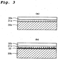
- Figure 3 shows two modes of roughening the contact surfaces.
- an undercoating primary layer 33 having a rough surface is formed by preparatory surface treatment atop the surface of a steel 30b, and a solid lubricating coating 31b and a solid corrosion protective coating 32b are formed in sequence atop the primary layer.
- the primary layer 33 is disposed between the contact surface of the steel 30b and the solid lubricating coating 31b.
- Examples of preparatory surface treatment to form a primary layer are chemical conversion treatment such as phosphate treatment (phosphating), oxalate treatment, and borate treatment (the surface roughness increases with the growth of the crystals which are formed by the chemical conversion treatment.), metal plating such as copper plating or iron plating (projections are preferentially plated, so the surface becomes slightly rougher), impact plating with zinc or a zinc alloy which forms a porous zinc or zinc-alloy coating, soft nitriding which forms a nitride layer (such as tufftriding), and composite metal plating which forms a porous coating containing fine solid particles dispersed in a metal matrix.
- chemical conversion treatment such as phosphate treatment (phosphating), oxalate treatment, and borate treatment (the surface roughness increases with the growth of the crystals which are formed by the chemical conversion treatment.)
- metal plating such as copper plating or iron plating (projections are preferentially plated, so the surface becomes slightly rougher)
- the surface roughness Rmax obtained by the preparatory surface treatment is preferably in the range of 5 - 40 ⁇ m. If Rmax is less than 5 ⁇ m, the adhesion of the solid lubricating coating to the surface and the ability of the surface to hold a coating may become inadequate. If Rmax exceeds 40 ⁇ m, the friction of the surface increases, and the solid lubricating coating may not withstand the shearing forces and compressive forces which the coating receives when a high pressure is applied to the surface during fastening, thereby easily causing the breakdown or peeling of the solid lubricating coating. Two or more types of preparatory surface treatment may be carried out for surface roughening.
- the duration of treatment may be set depending on the desired coating thickness to be formed, and it is normally up to 15 minutes.
- the surface to be treated may be pretreated with an aqueous solution containing colloidal titanium for surface modification prior to phosphating. After phosphating, it is preferable to perform rinsing with water or warm water followed by drying.
- Blast plating can be performed using, for example, plating particles having an iron-based core coated with a surface layer of zinc or a zinc alloy as blasting particles which are impacted against the contact surfaces of a pin and/or box to be plated.
- the amount of the surface layer of zinc or a zinc alloy in the particles is preferably in the range of 20 - 60 wt%, and the diameter of the particles is preferably in the range of 0.2 - 1.5 mm.
- Such particles can be prepared by a method in which an iron or iron alloy powder forming the core is plated with zinc or a zinc alloy (such as a Zn-Fe-Al alloy) and then heat treated to form an iron-zinc alloy layer at the interface between the core and the plating, or by a mechanical alloying method.
- An example of a commercially available product of such particles is "Z Iron" manufactured by Dowa Iron Powder Co., Ltd.
- a blasting device which can be used include a high pressure fluid blasting device which blows particles using a high pressure fluid such as compressed air, and a mechanical blasting device which utilizes an impeller or other rotating vanes.
- the thickness of the zinc or zinc alloy layer formed by impact plating is preferably 5 - 40 ⁇ m. If it is less than 5 ⁇ m, adequate corrosion resistance is not guaranteed in some cases. On the other hand, if it exceeds 40 ⁇ m, adhesion to the solid lubricating coating tends to decrease.
- a solid lubricating coating in the present invention is a coating comprising one or more types of solid lubricant powder and a binder as a matrix. Namely, it is a heterogeneous coating containing a solid lubricant powder bonded with a binder.
- the amount of solid lubricating powder in the solid lubricating coating (the total amount when using two or more types of powder) is preferably selected such that the mass ratio of the solid lubricating powder to the binder in the coating is in the range of 0.3 - 0.9. If the amount of the lubricating powder is too small, galling resistance decreases, and if it is too large, the adhesion and coating strength of the solid lubricating coating decrease. In the present invention, since the solid lubricating coating is overlaid with a solid corrosion protective coating, compared to the case in which the solid lubricating coating is the outermost layer, the content of the lubricating powder in a solid lubricating coating can be increased.
- the solid lubricating coating can contain one or more types of additional powders other than a solid lubricating powder.
- additional powders are zinc, copper, nickel, tin, or other metal powders and silica or other inorganic powders each for increasing corrosion resistance.
- the mass ratio of the total amount of the other powders and the lubricating powder to the amount of the binder is preferably at most 0.9.
- the binder of the solid lubricating coating is a material having the ability to form a film. It can be an organic resin or an inorganic polymeric compound. As the binder, the same sort of material as used for the material constituting the upper solid corrosion protective coating can be used, as described below more fully.
- the thickness of the solid lubricating coating is preferably at least 5 ⁇ m.
- the lubricating powder contained in the solid lubricating coating spreads over the entire contact surfaces of a threaded joint when it receives a high pressure so that it can exhibit excellent galling resistance. If the thickness of the solid lubricating coating is less than 5 ⁇ m, the absolute amount of the lubricating powder present on the contact surfaces becomes too small to exert its lubricating effect adequately. If the thickness of the solid lubricating coating exceeds 40 ⁇ m, the amount of tightening which is achieved by interference between male and female threads becomes inadequate, leading to a decrease in airtightness.
- a film forming material is used for both the binder of the solid lubricating coating and for the solid corrosion protective coating.
- an organic resin or an inorganic polymeric compound can be used.
- a preferred organic resin is one having heat resistance, a suitable hardness, and a suitable wear resistance.
- examples of such an organic resin include thermosetting resins such as epoxy resins, polyimide resins, polyamide-imide resins, polycarbodiimide resins, polyethersulfones, polyetheretherketones, phenolic resins, and furan resins, as well as polyethylene resins, silicone resins, and fluororesins.
- a solid lubricating coating or a solid corrosion protective coating can be formed by applying a resin coating composition (a solution or a dispersion of a resin or a resin itself in liquid form) followed by drying.
- a resin coating composition a solution or a dispersion of a resin or a resin itself in liquid form
- a lubricating powder is added to the resin coating composition and uniformly dispersed therein.
- the application of a resin coating composition is preferably followed by heat setting.
- the heat setting is preferably performed at a temperature of at least 120°C and more preferably 150 - 380°C.
- the duration of heating is preferably at least 30 minutes and more preferably 30 - 60 minutes.
- the heat setting may be carried out after forming the solid lubricating coating and again after forming the solid corrosion protective coating, or it may be carried out only after forming the solid corrosion protective coating.
- An inorganic polymeric compound is a compound having a structure in which metal-oxygen bonds such as Ti-O, Si-O, Zr-O, Mn-O, Ce-O, or Ba-O are three-dimensionally cross linked.
- Such an inorganic polymeric compound can be formed by hydrolysis and condensation of a hydrolyzable metal compound such as a metal alkoxide or a metal chloride.
- a hydrolyzable metal compound containing a functional group such as an amine or epoxy group as exemplified by a silane coupling agent or a titanate coupling agent can also be used to form the inorganic polymeric compound.
- a solid lubricating coating or a solid corrosion protective coating can be formed by application of a solution of the hydrolyzable metal compound or a partial hydrolysate thereof in a solvent, followed by, if necessary, humidifying treatment and/or heating.
- a lubricating powder is dispersed in the solution prior to application thereof.
- Humidifying treatment may be performed in order to promote the hydrolysis of the hydrolyzable metal compound. It can be carried out by allowing the applied coating to stand in air, preferably in a humidified air having a relative humidity of at least 70%, for a certain period. Preferably humidifying treatment is followed by heating in order to accelerate the hydrolysis of the metal compound and the condensation of the resulting hydrolysate and discharge of the by-products formed by the hydrolysis (an alcohol when the metal compound is a metal alkoxide) and condensation (water), thereby making it possible to form a coating in a short period of time. In addition, the adhesion of the resulting coating is strengthened.
- the heating is preferably carried out after evaporation of the solvent remaining in the applied coating, and the heating temperature is preferably a temperature in the range of 50 - 200° C, which is close to the boiling point of the alcohol by-product. Heating in an hot air oven is more effective.
- the solid corrosion protective coating is a nonporous coating which does not contain any solid particles. Like the binder of the solid corrosion protective coating, it can be formed from a film forming material.
- the solid corrosion protective coating is preferably formed essentially of an organic resin. It is also possible to form the solid corrosion protective coating from an inorganic polymeric compound, but a coating formed from an inorganic polymeric compound generally has a greater tendency toward the formation of voids than an organic resin coating and is inferior in corrosion preventing properties.
- the binder of the solid lubricating coating be the same resin as used for the solid corrosion protective coating so that the same organic resin is present in the binder of the lower solid lubricating coating and the upper solid corrosion protective coating.
- the thickness of the solid corrosion protective coating is preferably at least 5 ⁇ m. If the solid corrosion protective coating has a thickness of less than 5 ⁇ m, it may not provide a satisfactory corrosion preventing effect. If its thickness is larger than 40 ⁇ m, for the same reason as stated with respect to the solid lubricating coating, there is a concern that problems occur with respect to airtightness, galling resistance, and coating adhesion. However, depending upon the geometric shape of the threads, it is possible to make the coating thickness greater than 40 ⁇ m.
- the above-described solid lubricating coating and solid corrosion protective coating can be formed on the contact surfaces of one or both of the pin and the box.
- the object of the present invention can be adequately achieved even if these two coating layers are formed on the contact surfaces of only one member, so it is economical to form these coating layers on only one member of the pin and the box. In this case, the process of forming a coating on the box is easier than on the pin.
- a coupling is installed on a steel pipe for OCTG at only one end thereof, while the pin at the other end of the pipe and the box on one side of the coupling are exposed.
- a protector is often mounted on the exposed pin or box for protecting the threaded portions, but the protector does not prevent the passage of air or water.
- the pin at one end on which a box is not installed is exposed to air.
- the contact surfaces of the other member i.e., pin
- the contact surfaces of the other member can be coated with one or more coating layers by suitable surface treatment.
- This coating may be either a drying or nondrying coating as long as it is not harmful to the environment or humans.
- a Raydent Coating which is a metallic coating having a laminated layer of ultrafine ceramic particles supplied by Raydent Industrial Co., Ltd.
- Another option for such a coating is to form a solid corrosion protective coating as described above directly on the contact surfaces of the other member.
- a porous zinc or zinc alloy coating, a plated metal coating, and a solid corrosion protective coating have a good corrosion preventing effect, while the other coatings are highly effective at improving sliding properties.
- a plated metal coating for corrosion protection is preferably one having high corrosion preventing properties such as a plated coating of zinc, a zinc alloy, nickel, copper, or a copper-tin alloy.
- a phosphate coating are a manganese phosphate coating, a zinc phosphate coating, a zinc-calcium phosphate coating, and a zinc-iron phosphate coating.
- An oxalate coating can be a coating of a metal oxalate such as iron oxalate (FeC 2 O 4 ) and/or nickel oxalate (NiC 2 O 4 ) which is formed by immersion in an aqueous solution of oxalic acid (C 2 H 2 O 4) .
- a borate coating can be a coating of a metal borate such as potassium borate.
- the coating weight of these coatings may be the same as conventionally used for these coatings and can be determined so as to adequately impart corrosion preventing properties and/or lubricating properties without being excessive. It is possible to form two or more layers of these coatings, such as to form a phosphate coating, an oxalate coating, or a borate coating atop a porous zinc or zinc alloy coating or a plated metal coating.
- the thickness of a coating on the other member is preferably in the range of 5 - 40 ⁇ m for the same reason stated above.
- the surface roughness Rmax of the other member is preferably in the range of 1 - 10 ⁇ m. If the surface roughness of the contact surfaces of the other member (pin) is larger than 10 ⁇ m, there is the possibility of the solid corrosion protective coating or the solid lubricating coating formed on the box being damaged and peeled off by the pin at the time of fastening and loosening of a threaded joint.
- any of the above-described preparatory surface treatment for surface roughening can be utilized. Namely, any treatment for roughening the contact surfaces themselves such as pickling or blasting, or treatment for forming a primary coating with a rough surface such as impact plating with zinc or a zinc alloy, metal plating, soft nitriding treatment, composite metal plating, phosphating, oxalate treatment, or borate treatment can be carried out on the contact surfaces of the other member prior to forming a solid corrosion protective coating or a solid lubricating coating. It is also possible to employ two or more type of preparatory surface treatment sequentially.
- the surface roughness Rmax of the contact surfaces of the other member is at most 10 ⁇ m.
- the preparatory surface treatment for surface roughening of the contact surfaces of the other member is preferably controlled so as to ensure that such a preferable surface roughness is obtained after the solid corrosion protective coating or solid lubricating coating is formed on these surfaces.
- the contact surfaces including the male threaded portion and the unthreaded metal-to-metal contact portion of the pin will be referred to as the "pin surfaces”
- the contact surfaces including the female threaded portion and the unthreaded metal-to-metal contact portion of the box will be referred to as the "box surfaces”.
- each threaded joint was separately subjected to preparatory surface treatment and then to one or two types of surface treatment each to form a coating as shown in Table 2 and as described later for each example.
- the coating was indicated in the column of outermost layer in Table 2.
- the first and the second coatings were indicated in the columns of intermediate layer and outermost layer, respectively, in Table 2.
- the intermediate and outer layers are a solid lubricating coating and a solid corrosion protective layer.
- each of the solid lubricating coating and the solid corrosion protective coating was formed by air spray coating followed by heat setting which was carried out by heating at a temperature exceeding 100 °C for 30 minutes.
- the box surfaces were subjected to the salt spray test specified in JIS Z2371 for 100 hours. Thereafter, the box surfaces were observed, and a fastening and loosening test was then carried out on the threaded joint.
- a commercially-available rust preventive oil was applied to the pin surfaces and the box surfaces of each threaded joint, and the joint was left for one week. Thereafter, the rust preventive oil on the surfaces was wiped off, and after the box surfaces were observed, a fastening and loosening test was carried out on the threaded joint.
- Fastening was carried out at a fastening speed of 10 rpm with a fastening torque of 14 kN-m, and the occurrence of seizing or galling of the contact surfaces of the pin and the box after loosening was investigated.
- damages due to seizing which occurred during fastening were light and it was possible to resume fastening after repair, repair was carried out and fastening and loosening were continued.
- unrepairable severe seizing or galling occurred, the test was terminated.
- the box surfaces which had been finished by machine grinding were immersed for 10 minutes in a manganese phosphating solution (a manganese phosphate-type phosphating solution) at 80 - 95° C for preparatory surface treatment to form a primary coating which was a manganese phosphate coating with a thickness of 15 ⁇ m.
- a solid lubricating coating with a thickness of 30 ⁇ m was formed from an epoxy resin containing graphite powder with an average particle diameter of 10 ⁇ m and copper flaky powder with a maximum length of 15 ⁇ m.
- the mass ratio of graphite to epoxy resin (M in Table 2) in the solid lubricating coating was 0.6:1, and the mass ratio of copper powder to graphite (N in Table 2) therein was 0.2:1.
- a solid corrosion protective coating formed solely of an epoxy resin was formed to a thickness of 20 ⁇ m atop the solid lubricating coating.
- the box surfaces which had been finished by machine grinding were subjected to pickling for preparatory surface treatment to obtain a surface roughness of 10 ⁇ m.
- a solid lubricating coating with a thickness of 30 ⁇ m was formed from an epoxy resin containing molybdenum disulfide powder with an average particle diameter of 5 ⁇ m.
- the mass ratio M of molybdenum disulfide to epoxy resin in the solid lubricating coating was 0.7:1.
- a solid corrosion protective coating formed solely of epoxy resin was formed to a thickness of 20 ⁇ m atop this solid lubricating coating.
- the pin surfaces which had been finished by machine grinding were subjected to pickling for preparatory surface treatment to obtain a surface roughness of 10 ⁇ m.
- a solid lubricating coating with a thickness of 20 ⁇ m was formed from a furan resin containing molybdenum disulfide powder with an average particle diameter of 5 ⁇ m.
- the mass ratio M of molybdenum disulfide to furan resin in the solid lubricating coating was 0.3:1. No solid corrosion protective coating formed solely of epoxy resin was formed thereon.
- the box surfaces which had been finished by machine grinding were subjected as preparatory surface treatment to blast plating using particles having an iron core coated with zinc to form a porous zinc coating having a thickness of 7 ⁇ m.
- a solid lubricating coating having a thickness of 30 ⁇ m was formed from an epoxy resin containing molybdenum disulfide powder with an average particle diameter of 5 ⁇ m.
- the mass ratio M of molybdenum disulfide to epoxy resin in the solid lubricating coating was 0.7:1.
- a solid corrosion protective coating consisting solely of an epoxy resin and having a thickness of 20 ⁇ m was formed atop this solid lubricating coating.
- the box surfaces which had been finished by machine grinding were surface treated exactly in the same manner as described in Example 4.
- a porous zinc coating formed by blast plating, a solid lubricating coating containing molybdenum disulfide powder in an epoxy resin, and a solid corrosion protective coating of an epoxy resin were sequentially formed on the box surfaces.
- the pin surfaces were given a surface roughness of 10 ⁇ m by sandblasting using #80 sand, and a solid corrosion protective coating having a thickness of 20 ⁇ m and consisting solely of an epoxy resin was formed on these surfaces.
- the box surfaces which had been finished by machine grinding were subjected for preparatory surface treatment to blast plating using particles having an iron core coated with zinc to form a porous zinc coating having a thickness of 7 ⁇ m.
- a solid lubricating coating with a thickness of 30 ⁇ m and containing graphite powder with an average particle diameter of 10 ⁇ m and copper flaky powder with a maximum length of 15 ⁇ m in an epoxy resin was formed.
- the mass ratio M of graphite to epoxy resin in the solid lubricating coating was 0.6:1, and the mass ratio N of copper powder to graphite therein was 0.2:1.
- a solid corrosion protective coating with a thickness of 20 ⁇ m and consisting solely of an epoxy resin was formed atop this solid lubricating coating.
- the pin surfaces were given a surface roughness of 10 ⁇ m by sandblasting with #80 sand, and then a solid lubricating coating with a thickness of 20 ⁇ m and containing molybdenum disulfide powder in a furan resin with an average particle diameter of 5 ⁇ m was formed on these surfaces.
- the mass ratio M of molybdenum disulfide to furan resin in the solid lubricating coating was 0.3:1.
- the box surfaces which had been finished by machine grinding were immersed for 10 minutes in a manganese phosphating solution at 80 - 95 °C for preparatory surface treatment to form a manganese phosphate coating with a thickness of 15 ⁇ m.
- a compound grease meeting API standards was then applied as a lubricant.
- the box surfaces which had been finished by machine grinding were immersed for 10 minutes in a manganese phosphating solution at 80 - 95 °C for preparatory surface treatment to form a manganese phosphate coating with a thickness of 15 ⁇ m.
- a solid corrosion protective coating formed solely of an epoxy resin was formed to a thickness of 20 ⁇ m as an intermediate layer.
- a solid lubricating coating with a thickness of 30 ⁇ m was formed from an epoxy resin containing graphite powder with an average particle diameter of 10 ⁇ m and copper flaky powder with a maximum length of 15 ⁇ m.
- the mass ratio M of graphite to epoxy resin in the solid lubricating coating was 0.6:1, and the mass ratio N of copper powder to graphite therein was 0.2:1.
- the structure of these coatings was similar to one proposed in WO 2004/033951 in that it had a lower solid corrosion protective coating and an upper solid lubricating coating.
- pin surfaces which had been finished by machine grinding were subjected to surface treatment exactly in the same manner as described in Example 1, and they had a lower zinc phosphate coating with a thickness of 15 ⁇ m and an upper solid corrosion protective coating having a thickness of 20 ⁇ m and consisting solely of an epoxy resin.
- the box surfaces were exposed to the salt spray test for 100 hours. Upon observation of the box surfaces after the salt spray test, the occurrence of patina (verdigris) was found on the box surfaces. It is believed that the patina was formed by reacting the copper powder contained in the solid lubricating coating, which was the outermost layer in this example, with the oxygen in air in a humid atmosphere given by the salt spray test.
- the box surfaces which had been finished by machine grinding were immersed for 10 minutes in a manganese phosphating solution at 80 - 95 °C for preparatory surface treatment to form a manganese phosphate coating with a thickness of 15 ⁇ m.
- a solid lubricating coating having a thickness of 25 ⁇ m and containing molybdenum disulfide powder with an average particle diameter of 5 ⁇ m in a polyamide-imide resin was formed.
- the mass ratio M of molybdenum disulfide to polyamide-imide resin in the solid lubricating coating was 1:1. No solid corrosion protective coating was formed thereon.
- the box surfaces which had been finished by machine grinding were immersed for 10 minutes in a manganese phosphating solution at 80 - 95° C to form a manganese phosphate coating with a thickness of 15 ⁇ m.
- a solid lubricating coating with a thickness of 15 ⁇ m and containing graphite powder with an average particle diameter of 10 ⁇ m in an epoxy resin was formed on the resulting primary coating.
- the mass ratio M of graphite to epoxy resin in the solid lubricating coating was 1:1. No solid corrosion protective coating was formed thereon.
- the pin surfaces which had been finished by machine grinding were immersed for 10 minutes in a zinc phosphating solution at 75 - 85° C for preparatory surface treatment to form a zinc phosphate coating with a thickness of 15 ⁇ m.
- the box surfaces which had been finished by machine grinding were immersed for 10 minutes in a manganese phosphating solution at 80 - 95° C for preparatory surface treatment to form a manganese phosphate coating with a thickness of 15 ⁇ m.
- a solid corrosion protective coating with a thickness of 20 ⁇ m and made solely from an epoxy resin was formed.
- a solid lubricating coating which had a thickness of 25 ⁇ m and was made from a polyamide-imide resin containing molybdenum disulfide powder with an average particle diameter of 5 ⁇ m was formed.
- the mass ratio M of molybdenum disulfide to the polyamide-imide resin in the solid lubricating coating was 1:1.
- the structure of these coatings having a lower solid corrosion protective coating and an upper solid lubricating coating is the same as proposed in WO 2004/033951 .
Landscapes
- Chemical & Material Sciences (AREA)
- Engineering & Computer Science (AREA)
- Mechanical Engineering (AREA)
- Inorganic Chemistry (AREA)
- Chemical Kinetics & Catalysis (AREA)
- Organic Chemistry (AREA)
- Materials Engineering (AREA)
- Metallurgy (AREA)
- General Engineering & Computer Science (AREA)
- Mining & Mineral Resources (AREA)
- Life Sciences & Earth Sciences (AREA)
- Geology (AREA)
- Fluid Mechanics (AREA)
- Environmental & Geological Engineering (AREA)
- Physics & Mathematics (AREA)
- General Life Sciences & Earth Sciences (AREA)
- Geochemistry & Mineralogy (AREA)
- General Chemical & Material Sciences (AREA)
- Oil, Petroleum & Natural Gas (AREA)
- Non-Disconnectible Joints And Screw-Threaded Joints (AREA)
- Other Surface Treatments For Metallic Materials (AREA)
- Lubricants (AREA)
- Mutual Connection Of Rods And Tubes (AREA)
- Laminated Bodies (AREA)
- Application Of Or Painting With Fluid Materials (AREA)
Claims (10)
- Schraubverbindung für Stahlrohre (A), welche einen Einsteckteil (1) und einen Aufnahmeteil (2) mit jeweiligen Kontaktflächen, die einander kontaktieren, wenn die Verbindung gesichert wird, umfasst, wobei die Kontaktflächen von mindestens einem von Einsteckteil und Aufnahmeteil mit einer festen Schmierbeschichtung (31a, 31b), die ein festes Schmierpulver und ein Bindemittel umfasst, und mit einer Korrosionsschutzbeschichtung (32a, 32b), die keine oben auf der festen Schmierbeschichtung ausgebildeten festen Partikel enthält, beschichtet sind, dadurch gekennzeichnet, dass die Korrosionsschutzbeschichtung eine nichtporöse feste Korrosionsschutzbeschichtung ist.
- Schraubverbindung für Stahlrohre (A) nach Anspruch 1, dadurch gekennzeichnet, dass die feste Schmierbeschichtung (31a, 31b) auf den Kontaktflächen ausgebildet ist, die einer vorbereitenden Oberflächenbehandlung ausgewählt aus Beizen, Strahlputzen, Schlagplattieren mit Zink oder einer Zinklegierung, Metallisieren, Weichnitrieren, Verbundmetallplattieren, Phospatieren, Oxalatbehandlung und Boratbehandlung unterzogen wurden.
- Schraubverbindung für Stahlrohre (A) nach Anspruch 1 oder 2, dadurch gekennzeichnet, dass die Kontaktflächen des Aufnahmeteils (2) mit der festen Schmierbeschichtung (31a, 31b) und der festen Korrosionsschutzbeschichtung (32a, 32b) beschichtet sind.
- Schraubverbindung für Stahlrohre (A) nach Anspruch 1 oder 2, dadurch gekennzeichnet, dass die Kontaktflächen eines Elements von: Einsteckteil (1) und Aufnahmeteil (2) mit der festen Schmierbeschichtung (31a, 31b) und der festen Korrosionsschutzbeschichtung (32a, 32b) beschichtet sind und die Kontaktflächen des anderen Elements mit mindestens einer Schicht einer Beschichtung gewählt aus einer Zink- oder Zinklegierungsbeschichtung, einer metallisierten Beschichtung, einer Phosphatbeschichtung, einer Oxalatbeschichtung, einer Boratbeschichtung und entweder der festen Schmierbeschichtung oder der festen Korrosionsschutzbeschichtung beschichtet sind.
- Schraubverbindung für Stahlrohre (A) nach Anspruch 1 oder 2, dadurch gekennzeichnet, dass die Kontaktflächen eines Elements von: Einsteckteil (1) und Aufnahmeteil (2) mit der festen Schmierbeschichtung (31a, 31b) und der festen Korrosionsschutzbeschichtung (32a, 32b) beschichtet sind und die Kontaktflächen des anderen Elements einer vorbereitenden Oberflächenbehandlung ausgewählt aus Beizen, Strahlputzen, Schlagplattieren mit Zink oder einer Zinklegierung, Metallisieren, Weichnitrieren, Verbundmetallplattieren, Phospatieren, Oxalatbehandlung und Boratbehandlung unterzogen werden und dann mit entweder der festen Schmierbeschichtung oder der festen Korrosionsschutzbeschichtung beschichtet werden.
- Schraubverbindung für Stahlrohre (A) nach einem der Ansprüche 1 bis 5, dadurch gekennzeichnet, dass die feste Korrosionsschutzbeschichtung (32a, 32b) im Wesentlichen aus einem organischen Harz besteht.
- Schraubverbindung für Stahlrohre (A) nach einem der Ansprüche 1 bis 6, dadurch gekennzeichnet, dass das Bindemittel der festen Schmierbeschichtung (31a, 31b) ein organisches Harz umfasst und die feste Korrosionsschutzbeschichtung das gleiche organische Harz wie das Bindemittel umfasst.
- Schraubverbindung für Stahlrohre (A) nach einem der Ansprüche 1 bis 7, dadurch gekennzeichnet, dass die Dicke der festen Schmierbeschichtung (31a, 31b) 5 - 40 µm beträgt.
- Schraubverbindung für Stahlrohre (A) nach einem der Ansprüche 1 bis 7, dadurch gekennzeichnet, dass die Dicke der festen Korrosionsschutzbeschichtung (32, 32b) 5 - 40 µm beträgt.
- Schraubverbindung für Stahlrohre (A) nach einem der Ansprüche 1 bis 7, dadurch gekennzeichnet, dass die Dicke der gesamten Beschichtung aus fester Schmierbeschichtung (31a, 31b) und fester Korrosionsschutzbeschichtung (32a, 32b) höchstens 60 µm beträgt.
Priority Applications (1)
| Application Number | Priority Date | Filing Date | Title |
|---|---|---|---|
| PL06700861T PL1844255T3 (pl) | 2005-01-13 | 2006-01-11 | Złącze gwintowe do rur stalowych |
Applications Claiming Priority (2)
| Application Number | Priority Date | Filing Date | Title |
|---|---|---|---|
| JP2005006338 | 2005-01-13 | ||
| PCT/JP2006/300661 WO2006075774A1 (en) | 2005-01-13 | 2006-01-11 | Threaded joint for steel pipes |
Publications (4)
| Publication Number | Publication Date |
|---|---|
| EP1844255A1 EP1844255A1 (de) | 2007-10-17 |
| EP1844255A4 EP1844255A4 (de) | 2008-05-21 |
| EP1844255B1 EP1844255B1 (de) | 2009-12-30 |
| EP1844255B2 true EP1844255B2 (de) | 2018-07-04 |
Family
ID=36677788
Family Applications (1)
| Application Number | Title | Priority Date | Filing Date |
|---|---|---|---|
| EP06700861.5A Expired - Lifetime EP1844255B2 (de) | 2005-01-13 | 2006-01-11 | Schraubverbindung für stahlrohre |
Country Status (14)
| Country | Link |
|---|---|
| EP (1) | EP1844255B2 (de) |
| JP (1) | JP4687715B2 (de) |
| CN (1) | CN101103221B (de) |
| AR (1) | AR052084A1 (de) |
| AT (1) | ATE453825T2 (de) |
| BR (1) | BRPI0606637B1 (de) |
| CA (1) | CA2592730C (de) |
| DE (1) | DE602006011428D1 (de) |
| ES (1) | ES2336596T3 (de) |
| MX (1) | MX2007008518A (de) |
| NO (1) | NO342784B1 (de) |
| PL (1) | PL1844255T3 (de) |
| RU (1) | RU2349825C1 (de) |
| WO (1) | WO2006075774A1 (de) |
Families Citing this family (42)
| Publication number | Priority date | Publication date | Assignee | Title |
|---|---|---|---|---|
| JP5028923B2 (ja) | 2006-09-14 | 2012-09-19 | 住友金属工業株式会社 | 鋼管用ねじ継手 |
| US8322754B2 (en) | 2006-12-01 | 2012-12-04 | Tenaris Connections Limited | Nanocomposite coatings for threaded connections |
| WO2008125740A1 (fr) * | 2007-04-13 | 2008-10-23 | Vallourec Mannesmann Oil & Gas France | Element filete tubulaire muni d'un revetement protecteur sec |
| MY161993A (en) | 2007-12-04 | 2017-05-31 | Sumitomo Metal Ind | Threaded joint for pipes |
| US8622091B2 (en) | 2008-08-14 | 2014-01-07 | Nippon Steel & Sumitomo Metal Corporation | Protector for tubular threaded joint |
| US8261841B2 (en) * | 2009-02-17 | 2012-09-11 | Exxonmobil Research And Engineering Company | Coated oil and gas well production devices |
| JP5606802B2 (ja) | 2009-06-02 | 2014-10-15 | 新日鐵住金株式会社 | 鋼管ねじ継手の防錆に適した光硬化性組成物 |
| AU2009352058B2 (en) | 2009-09-02 | 2014-07-24 | Drilltec Patents & Technologies Corporation | Protector for tubular threaded joint |
| US8535762B2 (en) * | 2009-10-09 | 2013-09-17 | Tenaris Connections Limited | Tubular joint having wedge threads with surface coating |
| DE102010002579A1 (de) * | 2010-03-04 | 2011-09-08 | Robert Bosch Gmbh | Befestigungsmittel und zugehöriges Herstellungsverfahren |
| UA104975C2 (uk) * | 2010-11-05 | 2014-03-25 | Ніппон Стіл Енд Сумітомо Метал Корпорейшн | Нарізне з'єднання труб, що має поліпшені характеристики при низькій температурі |
| RU2479670C2 (ru) * | 2011-07-15 | 2013-04-20 | Государственное образовательное учреждение высшего профессионального образования "Вологодский государственный технический университет" (ВоГТУ) | Способ повышения износоустойчивости деталей путем нанесения пленки смазочной композиции на основе дисульфида молибдена на поверхности трения |
| CA2860499C (en) | 2012-01-19 | 2018-01-16 | Yasuhiro Yamamoto | Box protector for a threaded joint for pipes |
| JP5910284B2 (ja) * | 2012-04-23 | 2016-04-27 | Jfeスチール株式会社 | 鋼管用ねじ継手の皮膜形成方法および鋼管用ねじ継手製品 |
| EP2806188B1 (de) * | 2013-05-21 | 2016-04-27 | Aktiebolaget SKF | Nockenstößelrollenanordnung |
| CN103603608B (zh) * | 2013-11-28 | 2016-06-01 | 大庆市盛日石油技术开发有限公司 | 一种双向保护润滑耐磨接箍 |
| AR100953A1 (es) | 2014-02-19 | 2016-11-16 | Tenaris Connections Bv | Empalme roscado para una tubería de pozo de petróleo |
| US10508203B2 (en) | 2014-09-26 | 2019-12-17 | The Boeing Company | Compositions and coatings with non-chrome corrosion inhibitor particles |
| AT516684B1 (de) * | 2015-01-13 | 2018-08-15 | Voestalpine Tubulars Gmbh & Co Kg | Lösbare Gewindeverbindung mit asymmetrischer Beschichtung |
| FR3035475B1 (fr) * | 2015-04-23 | 2017-04-28 | Vallourec Oil & Gas France | Element filete tubulaire dote d'un revetement metallique antigrippage et d'une couche lubrifiante |
| FR3035474B1 (fr) * | 2015-04-23 | 2017-04-28 | Vallourec Oil & Gas France | Element filete tubulaire dote d'un revetement metallique anticorrosion et antigrippage |
| FR3035476B1 (fr) * | 2015-04-23 | 2017-04-28 | Vallourec Oil & Gas France | Joint filete tubulaire dote d'un revetement metallique sur le filetage et la portee d'etancheite |
| NL2014798B1 (en) * | 2015-05-12 | 2017-01-27 | Lubo Global Innovation B V | Treaded metallic fastener and process for coating a treaded metallic fastener. |
| JP6620513B2 (ja) * | 2015-10-23 | 2019-12-18 | 日本製鉄株式会社 | ステンレス鋼材の製造方法、及び、ステンレス鋼材の化成処理方法 |
| AR106975A1 (es) * | 2015-12-25 | 2018-03-07 | Nippon Steel & Sumitomo Metal Corp | Conexión roscada para caño o tubo y método para producir la conexión roscada para caño o tubo |
| AR107043A1 (es) * | 2015-12-25 | 2018-03-14 | Nippon Steel & Sumitomo Metal Corp | Conexión roscada para caño o tubo y método para producir la conexión roscada para caño o tubo |
| WO2019094622A1 (en) * | 2017-11-08 | 2019-05-16 | S.P.M. Flow Control, Inc. | Stay rod for a pump |
| CN109026958A (zh) * | 2018-08-30 | 2018-12-18 | 平湖巨龙紧固件有限公司 | 一种螺母 |
| TWI683967B (zh) * | 2018-12-28 | 2020-02-01 | 態金材料科技股份有限公司 | 製造防鏽蝕自攻螺絲之方法及其製品 |
| CN109811293A (zh) * | 2019-04-10 | 2019-05-28 | 吕喜鹏 | 一种水冷式柔性定位无芯轴装夹增材热加工设备 |
| JP7356130B2 (ja) * | 2019-06-25 | 2023-10-04 | 国立大学法人東京海洋大学 | スケール付着防止層、スケール付着防止層を有する構造体、スケール付着防止剤 |
| EP4108970A4 (de) * | 2020-02-19 | 2023-01-25 | Nippon Steel Corporation | Schraubkopplung für ein rohr und verfahren zum herstellen einer schraubkopplung für ein rohr |
| CN111764842A (zh) * | 2020-06-11 | 2020-10-13 | 上海海隆石油管材研究所 | 一种用于钻具接头表面处理的环保型工艺 |
| CA3182556A1 (en) | 2020-06-15 | 2021-12-23 | Takafumi Ozeki | Mechanical property measuring apparatus, mechanical property measuring method, substance manufacturing equipment, substance management method, and substance manufacturing method |
| UA130259C2 (uk) * | 2020-08-20 | 2025-12-31 | Ніппон Стіл Корпорейшн | Металева труба для нафтової свердловини та спосіб її виготовлення |
| CN117255887A (zh) * | 2021-04-28 | 2023-12-19 | 日本制铁株式会社 | 油井用钢管 |
| MX2023014265A (es) | 2021-05-31 | 2024-01-18 | Jfe Steel Corp | Agente para la formacion de una pelicula solida de recubrimiento lubricante, articulos tubulares para la industria petrolera, union roscada para articulos tubulares para la industria petrolera y metodo para la fabricacion de articulos tubulares para la industria petrolera. |
| JP7193681B1 (ja) | 2021-05-31 | 2022-12-20 | Jfeスチール株式会社 | 薬剤、油井管、及び油井管ねじ継手 |
| JP7470198B2 (ja) | 2021-05-31 | 2024-04-17 | Jfeスチール株式会社 | 固体潤滑被膜形成用の薬剤、油井管、及び油井管ねじ継手 |
| FR3126742B1 (fr) * | 2021-09-07 | 2024-01-19 | Vallourec Oil & Gas France | Lubrifiant solide pour ZnNi sur élément fileté tubulaire |
| WO2023153274A1 (ja) * | 2022-02-10 | 2023-08-17 | 日本製鉄株式会社 | 油井用金属管 |
| CN115709159B (zh) * | 2022-12-02 | 2023-09-29 | 陕西延长石油(集团)有限责任公司 | 一种油气田用高性能螺纹的制备方法 |
Citations (7)
| Publication number | Priority date | Publication date | Assignee | Title |
|---|---|---|---|---|
| US3290199A (en) † | 1963-05-31 | 1966-12-06 | American Mach & Foundry | Method of and apparatus for coating pipe couplings |
| EP0329990A1 (de) † | 1988-02-03 | 1989-08-30 | Nippon Steel Corporation | Steigrohrverbinder in einer Ölbohrung mit einer Schicht zum Schutz vor Korrosion |
| US6027145A (en) † | 1994-10-04 | 2000-02-22 | Nippon Steel Corporation | Joint for steel pipe having high galling resistance and surface treatment method thereof |
| JP2002327874A (ja) † | 2001-05-01 | 2002-11-15 | Sumitomo Metal Ind Ltd | 鋼管用ねじ継手 |
| EP1365183A1 (de) † | 2001-01-25 | 2003-11-26 | Sumitomo Metal Industries Limited | Gewindeverbindung für stahlrohr mit hervorragender fress- und korrosionsbeständigkeit |
| WO2004033951A1 (en) † | 2002-10-10 | 2004-04-22 | Tenaris Connections Ag | Threaded pipe with surface treatment |
| US20040224857A1 (en) † | 2003-03-19 | 2004-11-11 | Hendrik John | Method and composition for controlling galling |
Family Cites Families (13)
| Publication number | Priority date | Publication date | Assignee | Title |
|---|---|---|---|---|
| US3554258A (en) * | 1969-05-02 | 1971-01-12 | Usm Corp | Self-locking threaded element |
| SU1572423A3 (ru) * | 1984-08-30 | 1990-06-15 | Хантинг Ойлфилд Сервисиз (Юк) Лимитед (Фирма) | Резьбовое соединение труб |
| CN1015402B (zh) * | 1986-10-11 | 1992-02-05 | 瓦洛海克股份有限公司 | 在螺纹部分设有密封装置的钢管螺纹接头 |
| JPS63293384A (ja) * | 1987-05-27 | 1988-11-30 | 住友金属工業株式会社 | ねじ継手付frp管 |
| US5687999A (en) * | 1995-10-03 | 1997-11-18 | Vallourec Oil & Gas | Threaded joint for tubes |
| FR2742840B1 (fr) * | 1995-12-22 | 1998-02-27 | Vallourec Oil & Gas | Joint filete pour tubes metalliques avec revetement interieur |
| JP3656481B2 (ja) * | 1999-09-30 | 2005-06-08 | 住友金属工業株式会社 | 防錆油組成物とその被膜を形成した油井管用ねじ継手 |
| AU6727100A (en) * | 1999-08-27 | 2001-03-26 | Sumitomo Metal Industries Ltd. | Threaded joint for oil well pipe |
| CA2395943A1 (en) * | 1999-12-27 | 2001-07-05 | Shigeo Nagasaku | Screw joint for oil well pipe |
| JP4092871B2 (ja) * | 2000-12-04 | 2008-05-28 | 住友金属工業株式会社 | ねじ継手の潤滑処理に適した潤滑被膜形成用組成物 |
| JP4032801B2 (ja) * | 2001-04-11 | 2008-01-16 | 住友金属工業株式会社 | 鋼管用ねじ継手 |
| RU2258859C2 (ru) * | 2001-04-11 | 2005-08-20 | Сумитомо Метал Индастриз, Лтд. | Резьбовое соединение для стальных труб (варианты) |
| JP3870732B2 (ja) * | 2001-07-25 | 2007-01-24 | 住友金属工業株式会社 | 耐焼付き性に優れた鋼管用ねじ継手 |
-
2006
- 2006-01-11 JP JP2007533303A patent/JP4687715B2/ja not_active Expired - Fee Related
- 2006-01-11 EP EP06700861.5A patent/EP1844255B2/de not_active Expired - Lifetime
- 2006-01-11 WO PCT/JP2006/300661 patent/WO2006075774A1/en not_active Ceased
- 2006-01-11 BR BRPI0606637-2A patent/BRPI0606637B1/pt not_active IP Right Cessation
- 2006-01-11 DE DE602006011428T patent/DE602006011428D1/de not_active Expired - Lifetime
- 2006-01-11 MX MX2007008518A patent/MX2007008518A/es active IP Right Grant
- 2006-01-11 RU RU2007130709/06A patent/RU2349825C1/ru not_active IP Right Cessation
- 2006-01-11 PL PL06700861T patent/PL1844255T3/pl unknown
- 2006-01-11 AR ARP060100116A patent/AR052084A1/es active IP Right Grant
- 2006-01-11 CA CA002592730A patent/CA2592730C/en not_active Expired - Fee Related
- 2006-01-11 CN CN2006800020278A patent/CN101103221B/zh not_active Expired - Fee Related
- 2006-01-11 AT AT06700861T patent/ATE453825T2/de active
- 2006-01-11 ES ES06700861T patent/ES2336596T3/es not_active Expired - Lifetime
-
2007
- 2007-06-25 NO NO20073204A patent/NO342784B1/no not_active IP Right Cessation
Patent Citations (7)
| Publication number | Priority date | Publication date | Assignee | Title |
|---|---|---|---|---|
| US3290199A (en) † | 1963-05-31 | 1966-12-06 | American Mach & Foundry | Method of and apparatus for coating pipe couplings |
| EP0329990A1 (de) † | 1988-02-03 | 1989-08-30 | Nippon Steel Corporation | Steigrohrverbinder in einer Ölbohrung mit einer Schicht zum Schutz vor Korrosion |
| US6027145A (en) † | 1994-10-04 | 2000-02-22 | Nippon Steel Corporation | Joint for steel pipe having high galling resistance and surface treatment method thereof |
| EP1365183A1 (de) † | 2001-01-25 | 2003-11-26 | Sumitomo Metal Industries Limited | Gewindeverbindung für stahlrohr mit hervorragender fress- und korrosionsbeständigkeit |
| JP2002327874A (ja) † | 2001-05-01 | 2002-11-15 | Sumitomo Metal Ind Ltd | 鋼管用ねじ継手 |
| WO2004033951A1 (en) † | 2002-10-10 | 2004-04-22 | Tenaris Connections Ag | Threaded pipe with surface treatment |
| US20040224857A1 (en) † | 2003-03-19 | 2004-11-11 | Hendrik John | Method and composition for controlling galling |
Also Published As
| Publication number | Publication date |
|---|---|
| WO2006075774A8 (en) | 2006-09-21 |
| RU2349825C1 (ru) | 2009-03-20 |
| EP1844255A4 (de) | 2008-05-21 |
| CN101103221A (zh) | 2008-01-09 |
| AR052084A1 (es) | 2007-02-28 |
| ATE453825T2 (de) | 2010-01-15 |
| EP1844255A1 (de) | 2007-10-17 |
| BRPI0606637B1 (pt) | 2019-04-16 |
| JP2008527249A (ja) | 2008-07-24 |
| DE602006011428D1 (de) | 2010-02-11 |
| WO2006075774A1 (en) | 2006-07-20 |
| CA2592730C (en) | 2009-09-01 |
| ES2336596T3 (es) | 2010-04-14 |
| CN101103221B (zh) | 2011-10-05 |
| EP1844255B1 (de) | 2009-12-30 |
| BRPI0606637A2 (pt) | 2009-07-07 |
| CA2592730A1 (en) | 2006-07-20 |
| PL1844255T3 (pl) | 2010-06-30 |
| NO20073204L (no) | 2007-08-08 |
| JP4687715B2 (ja) | 2011-05-25 |
| NO342784B1 (no) | 2018-08-06 |
| MX2007008518A (es) | 2007-08-14 |
Similar Documents
| Publication | Publication Date | Title |
|---|---|---|
| EP1844255B2 (de) | Schraubverbindung für stahlrohre | |
| US7770935B2 (en) | Threaded joint for steel pipes | |
| EP1365183B2 (de) | Gewindeverbindung für stahlrohr mit hervorragender fress- und korrosionsbeständigkeit | |
| EP1736697B1 (de) | Gewindeverbindung für stahlrohr und verfahren zur herstellung derselben | |
| EP1378698B1 (de) | Gewindeverbindung für stahlrohr | |
| EP2154406B1 (de) | Gewindeverbindungsstück für Stahlrohre und Verfahren für dessen Oberflächenbehandlung | |
| EP2881454B1 (de) | Röhrenförmige gewindeverbindung und schmierbeschichtungsbildende zusammensetzung zur verwendung darin | |
| US20040195825A1 (en) | Threaded joint for steel pipes | |
| CN115968420B (zh) | 油井用金属管 | |
| JP3738703B2 (ja) | 鋼管用ねじ継手 | |
| JP3765243B2 (ja) | 鋼管用ねじ継手 | |
| JP2002327875A (ja) | 耐焼付き性、防錆性、気密性に優れた鋼管用ねじ継手 | |
| AU2022263900A1 (en) | Screw joint-equipped oil well pipe, method for producing oil well pipe connecting body which uses screw joint-equipped oil well pipe, and method for producing screw joint-equipped oil well pipe | |
| ES2356522T3 (es) | Unión roscada para tubería de acero. |
Legal Events
| Date | Code | Title | Description |
|---|---|---|---|
| PUAI | Public reference made under article 153(3) epc to a published international application that has entered the european phase |
Free format text: ORIGINAL CODE: 0009012 |
|
| 17P | Request for examination filed |
Effective date: 20070628 |
|
| AK | Designated contracting states |
Kind code of ref document: A1 Designated state(s): AT BE BG CH CY CZ DE DK EE ES FI FR GB GR HU IE IS IT LI LT LU LV MC NL PL PT RO SE SI SK TR |
|
| DAX | Request for extension of the european patent (deleted) | ||
| A4 | Supplementary search report drawn up and despatched |
Effective date: 20080421 |
|
| RAP1 | Party data changed (applicant data changed or rights of an application transferred) |
Owner name: VALLOUREC MANNESMANN OIL & GAS FRANCE Owner name: SUMITOMO METAL INDUSTRIES, LTD. |
|
| 17Q | First examination report despatched |
Effective date: 20080711 |
|
| GRAP | Despatch of communication of intention to grant a patent |
Free format text: ORIGINAL CODE: EPIDOSNIGR1 |
|
| GRAS | Grant fee paid |
Free format text: ORIGINAL CODE: EPIDOSNIGR3 |
|
| GRAA | (expected) grant |
Free format text: ORIGINAL CODE: 0009210 |
|
| AK | Designated contracting states |
Kind code of ref document: B1 Designated state(s): AT BE BG CH CY CZ DE DK EE ES FI FR GB GR HU IE IS IT LI LT LU LV MC NL PL PT RO SE SI SK TR |
|
| REG | Reference to a national code |
Ref country code: GB Ref legal event code: FG4D |
|
| REG | Reference to a national code |
Ref country code: CH Ref legal event code: EP |
|
| REG | Reference to a national code |
Ref country code: RO Ref legal event code: EPE |
|
| REG | Reference to a national code |
Ref country code: IE Ref legal event code: FG4D |
|
| REF | Corresponds to: |
Ref document number: 602006011428 Country of ref document: DE Date of ref document: 20100211 Kind code of ref document: P |
|
| REG | Reference to a national code |
Ref country code: ES Ref legal event code: FG2A Ref document number: 2336596 Country of ref document: ES Kind code of ref document: T3 |
|
| PG25 | Lapsed in a contracting state [announced via postgrant information from national office to epo] |
Ref country code: SE Free format text: LAPSE BECAUSE OF FAILURE TO SUBMIT A TRANSLATION OF THE DESCRIPTION OR TO PAY THE FEE WITHIN THE PRESCRIBED TIME-LIMIT Effective date: 20091230 Ref country code: LT Free format text: LAPSE BECAUSE OF FAILURE TO SUBMIT A TRANSLATION OF THE DESCRIPTION OR TO PAY THE FEE WITHIN THE PRESCRIBED TIME-LIMIT Effective date: 20091230 Ref country code: FI Free format text: LAPSE BECAUSE OF FAILURE TO SUBMIT A TRANSLATION OF THE DESCRIPTION OR TO PAY THE FEE WITHIN THE PRESCRIBED TIME-LIMIT Effective date: 20091230 |
|
| REG | Reference to a national code |
Ref country code: NL Ref legal event code: VDEP Effective date: 20091230 |
|
| LTIE | Lt: invalidation of european patent or patent extension |
Effective date: 20091230 |
|
| PG25 | Lapsed in a contracting state [announced via postgrant information from national office to epo] |
Ref country code: SI Free format text: LAPSE BECAUSE OF FAILURE TO SUBMIT A TRANSLATION OF THE DESCRIPTION OR TO PAY THE FEE WITHIN THE PRESCRIBED TIME-LIMIT Effective date: 20091230 Ref country code: LV Free format text: LAPSE BECAUSE OF FAILURE TO SUBMIT A TRANSLATION OF THE DESCRIPTION OR TO PAY THE FEE WITHIN THE PRESCRIBED TIME-LIMIT Effective date: 20091230 |
|
| PG25 | Lapsed in a contracting state [announced via postgrant information from national office to epo] |
Ref country code: PT Free format text: LAPSE BECAUSE OF FAILURE TO SUBMIT A TRANSLATION OF THE DESCRIPTION OR TO PAY THE FEE WITHIN THE PRESCRIBED TIME-LIMIT Effective date: 20100430 Ref country code: NL Free format text: LAPSE BECAUSE OF FAILURE TO SUBMIT A TRANSLATION OF THE DESCRIPTION OR TO PAY THE FEE WITHIN THE PRESCRIBED TIME-LIMIT Effective date: 20091230 Ref country code: IS Free format text: LAPSE BECAUSE OF FAILURE TO SUBMIT A TRANSLATION OF THE DESCRIPTION OR TO PAY THE FEE WITHIN THE PRESCRIBED TIME-LIMIT Effective date: 20100430 Ref country code: EE Free format text: LAPSE BECAUSE OF FAILURE TO SUBMIT A TRANSLATION OF THE DESCRIPTION OR TO PAY THE FEE WITHIN THE PRESCRIBED TIME-LIMIT Effective date: 20091230 Ref country code: BG Free format text: LAPSE BECAUSE OF FAILURE TO SUBMIT A TRANSLATION OF THE DESCRIPTION OR TO PAY THE FEE WITHIN THE PRESCRIBED TIME-LIMIT Effective date: 20100330 |
|
| PG25 | Lapsed in a contracting state [announced via postgrant information from national office to epo] |
Ref country code: SK Free format text: LAPSE BECAUSE OF FAILURE TO SUBMIT A TRANSLATION OF THE DESCRIPTION OR TO PAY THE FEE WITHIN THE PRESCRIBED TIME-LIMIT Effective date: 20091230 Ref country code: MC Free format text: LAPSE BECAUSE OF NON-PAYMENT OF DUE FEES Effective date: 20100131 Ref country code: BE Free format text: LAPSE BECAUSE OF FAILURE TO SUBMIT A TRANSLATION OF THE DESCRIPTION OR TO PAY THE FEE WITHIN THE PRESCRIBED TIME-LIMIT Effective date: 20091230 |
|
| REG | Reference to a national code |
Ref country code: CH Ref legal event code: PL |
|
| PLBI | Opposition filed |
Free format text: ORIGINAL CODE: 0009260 |
|
| PG25 | Lapsed in a contracting state [announced via postgrant information from national office to epo] |
Ref country code: LI Free format text: LAPSE BECAUSE OF NON-PAYMENT OF DUE FEES Effective date: 20100131 Ref country code: GR Free format text: LAPSE BECAUSE OF FAILURE TO SUBMIT A TRANSLATION OF THE DESCRIPTION OR TO PAY THE FEE WITHIN THE PRESCRIBED TIME-LIMIT Effective date: 20100331 Ref country code: CY Free format text: LAPSE BECAUSE OF FAILURE TO SUBMIT A TRANSLATION OF THE DESCRIPTION OR TO PAY THE FEE WITHIN THE PRESCRIBED TIME-LIMIT Effective date: 20091230 Ref country code: CH Free format text: LAPSE BECAUSE OF NON-PAYMENT OF DUE FEES Effective date: 20100131 |
|
| PLAX | Notice of opposition and request to file observation + time limit sent |
Free format text: ORIGINAL CODE: EPIDOSNOBS2 |
|
| 26 | Opposition filed |
Opponent name: TENARIS CONNECTIONS LIMITED Effective date: 20100929 |
|
| PG25 | Lapsed in a contracting state [announced via postgrant information from national office to epo] |
Ref country code: IE Free format text: LAPSE BECAUSE OF NON-PAYMENT OF DUE FEES Effective date: 20100111 Ref country code: DK Free format text: LAPSE BECAUSE OF FAILURE TO SUBMIT A TRANSLATION OF THE DESCRIPTION OR TO PAY THE FEE WITHIN THE PRESCRIBED TIME-LIMIT Effective date: 20091230 |
|
| PLAF | Information modified related to communication of a notice of opposition and request to file observations + time limit |
Free format text: ORIGINAL CODE: EPIDOSCOBS2 |
|
| PLBB | Reply of patent proprietor to notice(s) of opposition received |
Free format text: ORIGINAL CODE: EPIDOSNOBS3 |
|
| PG25 | Lapsed in a contracting state [announced via postgrant information from national office to epo] |
Ref country code: HU Free format text: LAPSE BECAUSE OF FAILURE TO SUBMIT A TRANSLATION OF THE DESCRIPTION OR TO PAY THE FEE WITHIN THE PRESCRIBED TIME-LIMIT Effective date: 20100701 Ref country code: LU Free format text: LAPSE BECAUSE OF NON-PAYMENT OF DUE FEES Effective date: 20100111 |
|
| PG25 | Lapsed in a contracting state [announced via postgrant information from national office to epo] |
Ref country code: TR Free format text: LAPSE BECAUSE OF FAILURE TO SUBMIT A TRANSLATION OF THE DESCRIPTION OR TO PAY THE FEE WITHIN THE PRESCRIBED TIME-LIMIT Effective date: 20091230 |
|
| APBM | Appeal reference recorded |
Free format text: ORIGINAL CODE: EPIDOSNREFNO |
|
| APBP | Date of receipt of notice of appeal recorded |
Free format text: ORIGINAL CODE: EPIDOSNNOA2O |
|
| APAH | Appeal reference modified |
Free format text: ORIGINAL CODE: EPIDOSCREFNO |
|
| RAP2 | Party data changed (patent owner data changed or rights of a patent transferred) |
Owner name: VALLOUREC MANNESMANN OIL & GAS FRANCE Owner name: NIPPON STEEL & SUMITOMO METAL CORPORATION |
|
| APBQ | Date of receipt of statement of grounds of appeal recorded |
Free format text: ORIGINAL CODE: EPIDOSNNOA3O |
|
| REG | Reference to a national code |
Ref country code: GB Ref legal event code: 732E Free format text: REGISTERED BETWEEN 20131010 AND 20131016 |
|
| RAP2 | Party data changed (patent owner data changed or rights of a patent transferred) |
Owner name: VALLOUREC OIL AND GAS FRANCE Owner name: NIPPON STEEL & SUMITOMO METAL CORPORATION |
|
| REG | Reference to a national code |
Ref country code: DE Ref legal event code: R082 Ref document number: 602006011428 Country of ref document: DE Representative=s name: LORENZ SEIDLER GOSSEL RECHTSANWAELTE PATENTANW, DE Effective date: 20140403 Ref country code: DE Ref legal event code: R081 Ref document number: 602006011428 Country of ref document: DE Owner name: VALLOUREC MANNESMANN OIL & GAS FRANCE, FR Free format text: FORMER OWNERS: VALLOUREC MANNESMANN OIL & GAS FRANCE, AULNOYE-AYMERIES, FR; SUMITOMO METAL INDUSTRIES, LTD., OSAKA, JP Effective date: 20140403 Ref country code: DE Ref legal event code: R081 Ref document number: 602006011428 Country of ref document: DE Owner name: NIPPON STEEL & SUMITOMO METAL CORPORATION, JP Free format text: FORMER OWNERS: VALLOUREC MANNESMANN OIL & GAS FRANCE, AULNOYE-AYMERIES, FR; SUMITOMO METAL INDUSTRIES, LTD., OSAKA, JP Effective date: 20140403 Ref country code: DE Ref legal event code: R081 Ref document number: 602006011428 Country of ref document: DE Owner name: VALLOUREC MANNESMANN OIL & GAS FRANCE, FR Free format text: FORMER OWNER: VALLOUREC MANNESMANN OIL & GAS , SUMITOMO METAL INDUSTRIES, LTD., , JP Effective date: 20140403 Ref country code: DE Ref legal event code: R081 Ref document number: 602006011428 Country of ref document: DE Owner name: NIPPON STEEL & SUMITOMO METAL CORPORATION, JP Free format text: FORMER OWNER: VALLOUREC MANNESMANN OIL & GAS , SUMITOMO METAL INDUSTRIES, LTD., , JP Effective date: 20140403 |
|
| PLAB | Opposition data, opponent's data or that of the opponent's representative modified |
Free format text: ORIGINAL CODE: 0009299OPPO |
|
| R26 | Opposition filed (corrected) |
Opponent name: TENARIS CONNECTIONS LIMITED Effective date: 20100929 |
|
| REG | Reference to a national code |
Ref country code: FR Ref legal event code: PLFP Year of fee payment: 11 |
|
| REG | Reference to a national code |
Ref country code: FR Ref legal event code: PLFP Year of fee payment: 12 |
|
| REG | Reference to a national code |
Ref country code: FR Ref legal event code: PLFP Year of fee payment: 13 |
|
| APBU | Appeal procedure closed |
Free format text: ORIGINAL CODE: EPIDOSNNOA9O |
|
| PGFP | Annual fee paid to national office [announced via postgrant information from national office to epo] |
Ref country code: CZ Payment date: 20171213 Year of fee payment: 13 |
|
| PGFP | Annual fee paid to national office [announced via postgrant information from national office to epo] |
Ref country code: PL Payment date: 20171128 Year of fee payment: 13 |
|
| PGFP | Annual fee paid to national office [announced via postgrant information from national office to epo] |
Ref country code: ES Payment date: 20180201 Year of fee payment: 13 |
|
| PUAH | Patent maintained in amended form |
Free format text: ORIGINAL CODE: 0009272 |
|
| STAA | Information on the status of an ep patent application or granted ep patent |
Free format text: STATUS: PATENT MAINTAINED AS AMENDED |
|
| 27A | Patent maintained in amended form |
Effective date: 20180704 |
|
| AK | Designated contracting states |
Kind code of ref document: B2 Designated state(s): AT BE BG CH CY CZ DE DK EE ES FI FR GB GR HU IE IS IT LI LT LU LV MC NL PL PT RO SE SI SK TR |
|
| REG | Reference to a national code |
Ref country code: DE Ref legal event code: R102 Ref document number: 602006011428 Country of ref document: DE |
|
| PG25 | Lapsed in a contracting state [announced via postgrant information from national office to epo] |
Ref country code: CZ Free format text: LAPSE BECAUSE OF FAILURE TO SUBMIT A TRANSLATION OF THE DESCRIPTION OR TO PAY THE FEE WITHIN THE PRESCRIBED TIME-LIMIT Effective date: 20091230 |
|
| REG | Reference to a national code |
Ref country code: AT Ref legal event code: PC Ref document number: 453825 Country of ref document: AT Kind code of ref document: T Owner name: NIPPON STEEL & SUMITOMO METAL CORPORATION, JP Effective date: 20181219 Ref country code: AT Ref legal event code: PC Ref document number: 453825 Country of ref document: AT Kind code of ref document: T Owner name: VALLOUREC OIL & GAS FRANCE, FR Effective date: 20181219 |
|
| PG25 | Lapsed in a contracting state [announced via postgrant information from national office to epo] |
Ref country code: ES Free format text: LAPSE BECAUSE OF FAILURE TO SUBMIT A TRANSLATION OF THE DESCRIPTION OR TO PAY THE FEE WITHIN THE PRESCRIBED TIME-LIMIT Effective date: 20180704 |
|
| REG | Reference to a national code |
Ref country code: DE Ref legal event code: R082 Ref document number: 602006011428 Country of ref document: DE Representative=s name: LORENZ SEIDLER GOSSEL RECHTSANWAELTE PATENTANW, DE Ref country code: DE Ref legal event code: R081 Ref document number: 602006011428 Country of ref document: DE Owner name: NIPPON STEEL CORP., JP Free format text: FORMER OWNERS: NIPPON STEEL & SUMITOMO METAL CORPORATION, TOKYO, JP; VALLOUREC MANNESMANN OIL & GAS FRANCE, AULNOYE-AYMERIES, FR Ref country code: DE Ref legal event code: R081 Ref document number: 602006011428 Country of ref document: DE Owner name: VALLOUREC MANNESMANN OIL & GAS FRANCE, FR Free format text: FORMER OWNERS: NIPPON STEEL & SUMITOMO METAL CORPORATION, TOKYO, JP; VALLOUREC MANNESMANN OIL & GAS FRANCE, AULNOYE-AYMERIES, FR |
|
| PGFP | Annual fee paid to national office [announced via postgrant information from national office to epo] |
Ref country code: RO Payment date: 20191220 Year of fee payment: 15 |
|
| PGFP | Annual fee paid to national office [announced via postgrant information from national office to epo] |
Ref country code: FR Payment date: 20191216 Year of fee payment: 15 |
|
| PGFP | Annual fee paid to national office [announced via postgrant information from national office to epo] |
Ref country code: AT Payment date: 20191227 Year of fee payment: 15 Ref country code: IT Payment date: 20200114 Year of fee payment: 15 Ref country code: DE Payment date: 20191231 Year of fee payment: 15 Ref country code: GB Payment date: 20200102 Year of fee payment: 15 |
|
| REG | Reference to a national code |
Ref country code: DE Ref legal event code: R119 Ref document number: 602006011428 Country of ref document: DE |
|
| REG | Reference to a national code |
Ref country code: AT Ref legal event code: MM01 Ref document number: 453825 Country of ref document: AT Kind code of ref document: T Effective date: 20210111 |
|
| GBPC | Gb: european patent ceased through non-payment of renewal fee |
Effective date: 20210111 |
|
| PG25 | Lapsed in a contracting state [announced via postgrant information from national office to epo] |
Ref country code: AT Free format text: LAPSE BECAUSE OF NON-PAYMENT OF DUE FEES Effective date: 20210111 Ref country code: FR Free format text: LAPSE BECAUSE OF NON-PAYMENT OF DUE FEES Effective date: 20210131 |
|
| PG25 | Lapsed in a contracting state [announced via postgrant information from national office to epo] |
Ref country code: RO Free format text: LAPSE BECAUSE OF NON-PAYMENT OF DUE FEES Effective date: 20210111 Ref country code: DE Free format text: LAPSE BECAUSE OF NON-PAYMENT OF DUE FEES Effective date: 20210803 Ref country code: GB Free format text: LAPSE BECAUSE OF NON-PAYMENT OF DUE FEES Effective date: 20210111 |
|
| PG25 | Lapsed in a contracting state [announced via postgrant information from national office to epo] |
Ref country code: IT Free format text: LAPSE BECAUSE OF NON-PAYMENT OF DUE FEES Effective date: 20210111 |
|
| REG | Reference to a national code |
Ref country code: AT Ref legal event code: UEP Ref document number: 453825 Country of ref document: AT Kind code of ref document: T Effective date: 20180704 |
|
| PG25 | Lapsed in a contracting state [announced via postgrant information from national office to epo] |
Ref country code: PL Free format text: THE PATENT HAS BEEN ANNULLED BY A DECISION OF A NATIONAL AUTHORITY Effective date: 20180704 |
|
| PG25 | Lapsed in a contracting state [announced via postgrant information from national office to epo] |
Ref country code: PL Free format text: THE PATENT HAS BEEN ANNULLED BY A DECISION OF A NATIONAL AUTHORITY Effective date: 20180704 |