EP1843506A2 - Appareil et procédé pour communications numériques sans fil - Google Patents
Appareil et procédé pour communications numériques sans fil Download PDFInfo
- Publication number
- EP1843506A2 EP1843506A2 EP07014948A EP07014948A EP1843506A2 EP 1843506 A2 EP1843506 A2 EP 1843506A2 EP 07014948 A EP07014948 A EP 07014948A EP 07014948 A EP07014948 A EP 07014948A EP 1843506 A2 EP1843506 A2 EP 1843506A2
- Authority
- EP
- European Patent Office
- Prior art keywords
- pilot symbol
- signal
- symbol
- pilot
- immediately before
- Prior art date
- Legal status (The legal status is an assumption and is not a legal conclusion. Google has not performed a legal analysis and makes no representation as to the accuracy of the status listed.)
- Granted
Links
Images


Classifications
-
- H—ELECTRICITY
- H04—ELECTRIC COMMUNICATION TECHNIQUE
- H04L—TRANSMISSION OF DIGITAL INFORMATION, e.g. TELEGRAPHIC COMMUNICATION
- H04L7/00—Arrangements for synchronising receiver with transmitter
- H04L7/04—Speed or phase control by synchronisation signals
-
- H—ELECTRICITY
- H04—ELECTRIC COMMUNICATION TECHNIQUE
- H04L—TRANSMISSION OF DIGITAL INFORMATION, e.g. TELEGRAPHIC COMMUNICATION
- H04L27/00—Modulated-carrier systems
- H04L27/0008—Modulated-carrier systems arrangements for allowing a transmitter or receiver to use more than one type of modulation
-
- H—ELECTRICITY
- H04—ELECTRIC COMMUNICATION TECHNIQUE
- H04L—TRANSMISSION OF DIGITAL INFORMATION, e.g. TELEGRAPHIC COMMUNICATION
- H04L27/00—Modulated-carrier systems
- H04L27/18—Phase-modulated carrier systems, i.e. using phase-shift keying
- H04L27/20—Modulator circuits; Transmitter circuits
- H04L27/2032—Modulator circuits; Transmitter circuits for discrete phase modulation, e.g. in which the phase of the carrier is modulated in a nominally instantaneous manner
- H04L27/2053—Modulator circuits; Transmitter circuits for discrete phase modulation, e.g. in which the phase of the carrier is modulated in a nominally instantaneous manner using more than one carrier, e.g. carriers with different phases
- H04L27/206—Modulator circuits; Transmitter circuits for discrete phase modulation, e.g. in which the phase of the carrier is modulated in a nominally instantaneous manner using more than one carrier, e.g. carriers with different phases using a pair of orthogonal carriers, e.g. quadrature carriers
-
- H—ELECTRICITY
- H04—ELECTRIC COMMUNICATION TECHNIQUE
- H04L—TRANSMISSION OF DIGITAL INFORMATION, e.g. TELEGRAPHIC COMMUNICATION
- H04L27/00—Modulated-carrier systems
- H04L27/32—Carrier systems characterised by combinations of two or more of the types covered by groups H04L27/02, H04L27/10, H04L27/18 or H04L27/26
- H04L27/34—Amplitude- and phase-modulated carrier systems, e.g. quadrature-amplitude modulated carrier systems
- H04L27/3405—Modifications of the signal space to increase the efficiency of transmission, e.g. reduction of the bit error rate, bandwidth, or average power
-
- H—ELECTRICITY
- H04—ELECTRIC COMMUNICATION TECHNIQUE
- H04L—TRANSMISSION OF DIGITAL INFORMATION, e.g. TELEGRAPHIC COMMUNICATION
- H04L27/00—Modulated-carrier systems
- H04L27/32—Carrier systems characterised by combinations of two or more of the types covered by groups H04L27/02, H04L27/10, H04L27/18 or H04L27/26
- H04L27/34—Amplitude- and phase-modulated carrier systems, e.g. quadrature-amplitude modulated carrier systems
- H04L27/345—Modifications of the signal space to allow the transmission of additional information
- H04L27/3455—Modifications of the signal space to allow the transmission of additional information in order to facilitate carrier recovery at the receiver end, e.g. by transmitting a pilot or by using additional signal points to allow the detection of rotations
-
- H—ELECTRICITY
- H04—ELECTRIC COMMUNICATION TECHNIQUE
- H04L—TRANSMISSION OF DIGITAL INFORMATION, e.g. TELEGRAPHIC COMMUNICATION
- H04L7/00—Arrangements for synchronising receiver with transmitter
- H04L7/04—Speed or phase control by synchronisation signals
- H04L7/06—Speed or phase control by synchronisation signals the synchronisation signals differing from the information signals in amplitude, polarity or frequency or length
-
- H—ELECTRICITY
- H04—ELECTRIC COMMUNICATION TECHNIQUE
- H04L—TRANSMISSION OF DIGITAL INFORMATION, e.g. TELEGRAPHIC COMMUNICATION
- H04L27/00—Modulated-carrier systems
- H04L27/0014—Carrier regulation
- H04L2027/0024—Carrier regulation at the receiver end
-
- H—ELECTRICITY
- H04—ELECTRIC COMMUNICATION TECHNIQUE
- H04L—TRANSMISSION OF DIGITAL INFORMATION, e.g. TELEGRAPHIC COMMUNICATION
- H04L27/00—Modulated-carrier systems
- H04L27/0014—Carrier regulation
- H04L2027/0083—Signalling arrangements
- H04L2027/0087—Out-of-band signals, (e.g. pilots)
-
- H—ELECTRICITY
- H04—ELECTRIC COMMUNICATION TECHNIQUE
- H04L—TRANSMISSION OF DIGITAL INFORMATION, e.g. TELEGRAPHIC COMMUNICATION
- H04L27/00—Modulated-carrier systems
- H04L27/0014—Carrier regulation
- H04L2027/0083—Signalling arrangements
- H04L2027/0089—In-band signals
- H04L2027/0093—Intermittant signals
Definitions
- the present invention relates to an apparatus and method for digital wireless communications using a multivalue modulation type.
- FIG.1 shows a frame configuration according to a 16QAM system.
- this frame configuration has one pilot symbol inserted for every N-1 information symbols.
- quasi-coherent detection is performed by estimating the reference phase, amount of frequency offset and amount of amplitude distortion using pilot symbols.
- FIG.2A and FIG.2B are diagrams to explain the relationship between the time and amplitude of a reception signal.
- reference code 1 indicates the time when pilot symbol 3 is detected with an ideal judgment time and reference code 2 indicates the time when pilot symbol 3 is detected with a time offset (jitter) generated.
- Reference code 4 indicates the information symbols immediately before and after pilot symbol 3.
- Both a transmitter and receiver are provided with their respective clock generation functions. Because of this, the receiver has different clock generation sources, and therefore the receiver may detect waves at timing such as time 2, at which a time offset from ideal judgment time 1 has occurred. At this time, as shown in FIG.2A and FIG.2B, the time offset originates errors (amplitude errors) X I and X Q from the signal point. This deteriorates the error rate. Furthermore, the receiver estimates the phase, amplitude variation and frequency offset on the I-Q plane from the pilot symbol. However, when detected at time 2 when the time offset occurred, the pilot symbol signal has an error from the pilot symbol signal point, and therefore the accuracy in estimating the phase, amplitude variation and frequency offset deteriorates.
- a digital wireless communication apparatus that uses a modulation type including QPSK modulation and modulates the signal points of each one symbol immediately before and after a pilot symbol using a modulation type different from the modulation type for the pilot symbol in a frame configuration with one pilot symbol inserted for every 3 or more symbols.
- this objective is also achieved by a digital wireless communication apparatus that increases the amplitude at pilot symbol signal points more than the maximum amplitude at signal points according to the multivalue modulation type with 8 or more values.
- This apparatus can not only suppress deterioration in the accuracy in estimating the reference phase, amount of frequency offset by a pilot symbol in quasi-coherent detection with symbols whose symbol synchronization is not completely established, but also improve the bit error rate characteristic in the signal to noise ratio without deteriorating the power efficiency of the power amplifier on the transmitting side.
- the simplest pilot symbol configuration is to have 3 consecutive pilot symbols as shown in FIG.3. In such a configuration, even if a time offset occurs, the error from a pilot symbol signal point reduces because there are 3 consecutive pilot symbols.
- the present invention suppresses deterioration of the information transmission efficiency and suppresses errors from pilot symbol signal points when a time offset occurs by modulating symbols immediately before and after a pilot symbol according to a modulation type different from the pilot symbol modulation type.
- the present invention can suppress deterioration of the error rate by suppressing deterioration of the accuracy in estimating the phase, amplitude variation and frequency offset on the I-Q plane.
- the present specification includes a 64QAM system, 32QAM system, 16QAM system, 8PSK modulation type, QPSK modulation type, 16APSK modulation type and ⁇ /4-shift DQPSK modulation type.
- FIG.4 is a block diagram showing a configuration of the transmitter side of a digital wireless communication apparatus of the present invention.
- FIG.5 is a block diagram showing a configuration of the receiver side of a digital wireless communication apparatus of the present invention.
- FIG.6A is a diagram showing a frame configuration used in the digital wireless communication apparatus of the present invention.
- transmission data are sent to quadrature baseband signal generating section (for multivalue modulation type) 101 and quadrature baseband signal generating section (for modulation type for symbols immediately before and after PL) 102.
- Frame timing signal generating section 108 generates a frame timing signal at timing indicating a frame configuration shown in FIG.6A and outputs the frame timing signal to quadrature baseband signal generating section (for multivalue modulation type) 101, quadrature baseband signal generating section (for modulation type for symbols immediately before and after PL) 102 and quadrature baseband signal generating section (for PL) 103.
- Quadrature baseband signal generating section (for multivalue modulation type) 101 receives transmission data and a frame timing signal as inputs and if the frame timing signal indicates a multivalue modulation symbol, quadrature baseband signal generating section (for multivalue modulation type) 101 outputs the I component of the quadrature baseband signal for the multivalue modulation type to I component switching section 104 and outputs the Q component of the quadrature baseband signal for the multivalue modulation type to Q component switching section 105.
- Quadrature baseband signal generating section (for modulation type for symbols immediately before and after PL) 102 receives transmission data and a frame timing signal as inputs and if the frame timing signal indicates a symbol immediately before or after the pilot symbol, quadrature baseband signal generating section (for modulation type for symbols immediately before and after PL) 102 outputs the I component of the quadrature baseband signal for the modulation type for symbols immediately before and after PL to I component switching section 104 and outputs the Q component of the quadrature baseband signal for the modulation type for symbols immediately before and after PL to Q component switching section 105.
- Quadrature baseband signal generating section (for PL) 103 receives a frame timing signal as an input and if the frame timing signal indicates a pilot symbol, quadrature baseband signal generating section (for PL) 103 outputs the I component of the pilot symbol quadrature baseband signal to I component switching section 104 and outputs the Q component of the pilot symbol quadrature baseband signal to Q component switching section 105.
- I component switching section 104 receives the I component of the quadrature baseband signal for the multivalue modulation type, the I component of quadrature baseband signal for symbols immediately before and after PL and the I component of the PL quadrature baseband signal and a frame timing signal as inputs, and switches between the I component of the quadrature baseband signal for the multivalue modulation type, the I component of quadrature baseband signal for symbols immediately before and after PL and the I component of pilot symbol quadrature baseband signal according to the frame timing signal and outputs them to a section for radio frequency (radio section) 106 as the I component of the transmission quadrate baseband signal.
- radio section radio frequency
- Q component switching section 105 receives the Q component of the quadrature baseband signal for the multivalue modulation type, the Q component of quadrature baseband signal for symbols immediately before and after PL and the Q component of the PL quadrature baseband signal and a frame timing signal as inputs, and switches between the Q component of the quadrature baseband signal for the multivalue modulation type, the Q component of quadrature baseband signal for symbols immediately before and after PL and the Q component of pilot symbol quadrature baseband signal according to the frame timing signal and outputs them to radio section 106 as the Q component of the transmission quadrate baseband signal.
- Radio section 106 receives the I component and Q component of the transmission quadrature baseband signal as inputs, carries out predetermined radio processing on the baseband signal and then outputs a transmission signal. This transmission signal is amplified by power amplifier 107 and the amplified transmission signal is output from transmission antenna 109.
- radio section 202 receives the signal received from antenna 201 as an input, quadrature-modulates the input signal and outputs the I component and Q component of the reception quadrature baseband signal.
- Frame timing signal generating section 205 receives the I component and Q component of the reception quadrature baseband signal as inputs, detects a frame configuration shown in FIG.6A and outputs a frame timing signal to multivalue modulation type detection section 207, frequency offset amount estimating section 204 and modulation type detection section (for symbols immediately before and after PL) 208.
- Amplitude distortion amount estimating section 203 receives the I component and Q component of the reception quadrature baseband signal and frame timing signal as inputs, extracts a pilot symbol, estimates the amount of amplitude distortion from the I component and Q component of the pilot symbol quadrature baseband signal and outputs the amplitude distortion amount estimation signal to multivalue modulation type detection section 207 and modulation type detection section (for symbols immediately before and after PL) 208.
- Frequency offset amount estimating section 204 receives the I component and Q component of the reception quadrature baseband signal and frame timing signal as inputs, extracts a pilot symbol, estimates the amount of frequency offset from the I component and Q component of the pilot symbol quadrature baseband signal and outputs the frequency offset amount estimating signal to multivalue modulation type detection section 207 and modulation type detection section (for symbols immediately before and after PL) 208.
- Multivalue modulation type detection section 207 receives the I component and Q component of the reception quadrature baseband signal, frame timing signal, amplitude distortion amount estimating signal and frequency offset estimating signal as inputs, carries out detection when the input is a multivalue modulation type symbol and outputs a reception digital signal according to the multivalue modulation type.
- Modulation type detection section (for symbols immediately before and after PL) 208 receives the I component and Q component of the reception quadrature baseband signal, frame timing signal, amplitude distortion amount estimating signal and frequency offset estimating signal as inputs, carries out detection when the inputs are symbols immediately before and after a pilot symbol and outputs a reception digital signal according to the modulation type of the symbols immediately before and after the pilot symbol.
- a signal in a frame configuration as shown in FIG. 6A is transmitted/received. That is, the modulation type that modulates pilot symbols is different from the modulation type that modulates symbol 301 immediately before the pilot symbol and symbol 302 immediately after the pilot symbol. It is especially desirable that the number of multivalues in the modulation type for modulating symbols immediately before and after the pilot symbol be smaller than the number of multivalues in the modulation type for modulating pilot symbols.
- the modulation type for modulating pilot symbols is different from the modulation type for modulating symbols immediately before and after a pilot symbol, it is possible to suppress errors from pilot symbol signal points when a time offset occurs while suppressing deterioration of the information transmission efficiency. As a result, it is possible to suppress deterioration of the accuracy in estimating the phase, amplitude variation and frequency offset on the I-Q plane and suppress deterioration of the error rate.
- the method for differentiating the modulation type for modulating pilot symbols from the modulation type for modulating symbols immediately before and after a pilot symbol includes, for example, a method of placing two or more signal points of each one symbol immediately before and after a pilot symbol on a virtual line connecting the pilot symbol signal point and the origin on the in-phase I - quadrature Q plane.
- the digital wireless communication apparatus of the present invention has both the configuration on the transmitter side shown in FIG.4 and the configuration on the receiver side shown in FIG.5.
- the configurations in FIG.4 and FIG.5 are only examples and the present invention is not limited to these examples only.
- FIG.7 shows a signal space diagram on the in-phase I - quadrature Q plane according to a 16APSK modulation type, which is an example of a multivalue modulation type with 8 or more values, indicating pilot symbol signal points and signal points of one symbol before and after the pilot symbols.
- reference codes 401 indicate signal points according to the 16APSK modulation type
- reference code 402 indicates the pilot symbol signal point
- reference codes 403 indicate the signal points of each one symbol immediately before and after the pilot symbol.
- reference code 404 is a virtual line connecting the pilot symbol signal point and the origin on the I-Q plane, and two or more signal points 403 of each one symbol immediately before and after the pilot symbol are placed on virtual line 404 connecting the pilot symbol signal point 402 and the origin.
- FIG.8 shows a frame configuration example of symbols and pilot symbols modulated according to the 16APSK modulation type.
- Reference code 301 indicates one symbol immediately before a pilot symbol and reference code 302 indicates one symbol immediately after the pilot symbol.
- 2 or more signal points of one symbol 301 immediately before the pilot symbol and one symbol 302 immediately after the pilot symbol are placed on virtual line 404 connecting pilot symbol signal point 402 and the origin on the in-phase I - quadrature Q plane.
- the transmission data is a digital signal modulated according to the modulation type shown in FIG. 7 and FIG.8, even if symbol synchronization is not completely established, the pilot symbol transitions on the virtual line connecting the pilot symbol and the origin on the in-phase I - quadrature Q plane, and therefore the present embodiment demonstrates the effects shown in FIG. 6B and FIG.6C, making it possible to suppress deterioration of the accuracy in estimating the reference phase and the amount of frequency offset by the pilot symbol. This improves the bit error rate characteristic in the carrier to noise ratio during detection of a reception signal.
- the locations of the pilot symbol signal point and signal points of each one symbol immediately before and after the pilot symbol on the in-phase I - quadrature Q plane are not limited to FIG.7.
- the frame configuration is not limited to FIG.8, either.
- the present embodiment explains the case where the multivalue modulation type with 8 or more values is a 16APSK modulation type, but the multivalue modulation type with 8 or more values is not limited to this.
- the digital wireless communication apparatus places signal points of each one symbol immediately before and after the pilot symbol on a virtual line connecting the origin and pilot symbol signal point on the in-phase - quadrature plane, in a frame configuration in which one pilot symbol is inserted for every 3 symbols according to the modulation type including a multivalue modulation type with 8 or more values, and in this way can suppress deterioration of the accuracy in estimating the reference phase and the amount of frequency offset by the pilot symbol in quasi-coherent detection of symbols whose symbol synchronization is not completely established, improving the bit error rate characteristic in the signal to noise ratio.
- FIG.9 shows a signal space diagram according to a multivalue quadrature amplitude modulation (QAM) system with 8 or more values on the in-phase I - quadrature Q plane and shows pilot symbol signal point and signal points of each one symbol immediately before and after the pilot symbol.
- reference codes 501 indicate the signal points according to the multivalue QAM system
- reference code 502 indicates a pilot symbol signal point
- reference codes 503 indicate signal points of each one symbol immediately before and after the pilot symbol.
- Reference code 504 is a virtual line connecting the pilot symbol signal point and the origin on the I-Q plane. Two or more signal points 503 of each one symbol immediately before and after the pilot symbol are placed on virtual line 504 connecting pilot symbol signal point 502 and the origin.
- FIG.10 shows a frame configuration example of symbols and pilot symbols modulated according to the multivalue QAM system with 8 or more values.
- Reference code 301 indicates one symbol immediately before the pilot symbol and reference code 302 indicates one symbol immediately after the pilot symbol.
- two or more symbols 301 immediately before the pilot symbol and symbols 302 immediately after the pilot symbol are placed on virtual line 504 connecting pilot symbol signal point 502 and the origin on the in-phase I - quadrature Q plane.
- the pilot symbol transitions on the virtual line connecting the pilot symbol and the origin on the in-phase I - quadrature Q plane, and therefore the present embodiment demonstrates the effects shown in FIG.6B and FIG.6C, making it possible to suppress deterioration of the accuracy in estimating the reference phase and the amount of frequency offset by the pilot symbol. This improves the bit error rate characteristic in the signal to noise ratio during detection of the reception signal.
- pilot symbol signal point and signal points of each one symbol immediately before and after the pilot symbol are not limited to FIG.9.
- frame configuration is not limited to FIG.10.
- the digital wireless communication apparatus places two or more signal points of each one symbol immediately before and after the pilot symbol on a virtual line connecting the origin and pilot symbol signal point on the in-phase - quadrature plane, in a frame configuration in which one pilot symbol is inserted for every 3 or more symbols according to the modulation type including the multivalue QAM systems with 8 or more values, and in this way can suppress deterioration of the accuracy in estimating the reference phase and the amount of frequency offset by the pilot symbol in quasi-coherent detection of symbols whose symbol synchronization is not completely established, improving the bit error rate characteristic in the signal to noise ratio.
- FIG.11 shows a signal space diagram according to a 16QAM system on the in-phase I - quadrature Q plane and shows a pilot symbol signal point and signal points of each one symbol immediately before and after the pilot symbol.
- reference codes 601 indicate signal points according to the 16QAM system
- reference code 602 indicates the pilot symbol signal point
- reference codes 603 indicate signal points of each one symbol immediately before and after the pilot symbol.
- Reference code 604 is a virtual line connecting the pilot symbol signal point and the origin on the I-Q plane. Two or more signal points 603 of each one symbol immediately before and after the pilot symbol are placed on virtual line 604 connecting pilot symbol signal point 602 and the origin.
- FIG.12 shows a frame configuration example of symbols modulated according to the 64QAM system and pilot symbols.
- Reference code 301 indicates one symbol immediately before the pilot symbol and reference code 302 indicates one symbol immediately after the pilot symbol.
- two or more signal points 603 of one symbol 301 immediately before the pilot symbol and one symbol 302 immediately after the pilot symbol are placed on virtual line 604 connecting signal point 602 of the pilot symbol and the origin on the in-phase I - quadrature Q plane.
- the pilot symbol transitions on the virtual line connecting the pilot symbol and the origin on the in-phase I - quadrature Q plane, and therefore the present embodiment demonstrates the effects shown in FIG.6B and FIG.6C, making it possible to suppress deterioration of the accuracy in estimating the reference phase and the amount of frequency offset by the pilot symbol. This improves the bit error rate characteristic in the signal to noise ratio during detection of the reception signal.
- the locations of the pilot symbol signal point and signal points of each one symbol immediately before and after the pilot symbol on the in-phase I - quadrature Q plane are not limited to FIG.11. Moreover, the frame configuration is not limited to FIG.12.
- FIG.13 shows another signal space diagram example according to the 64QAM system on the in-phase I - quadrature Q plane and shows a pilot symbol signal point and signal points of each one symbol immediately before and after the pilot symbol.
- reference codes 701 and 701-A indicate signal points according to the 64QAM system
- reference codes 701-A indicate signal points of each one symbol immediately before and after the pilot symbol
- reference code 702 indicates a pilot symbol signal point
- reference code 703 indicates a virtual line connecting the pilot symbol signal point and the origin on the I-Q plane.
- pilot symbol signal point 702 and signal points 701-A on virtual line 703 connecting this and the origin are designated as the signal points of symbol 301 immediately before the pilot symbol and the signal point of one symbol 302 immediately after the pilot symbol
- the pilot symbol transitions on the virtual line connecting the pilot symbol and the origin on the in-phase I - quadrature Q plane even if symbol synchronization is not completely established, and therefore it is possible to suppress deterioration of the accuracy in estimating the reference phase and the amount of frequency offset by the pilot symbol.
- This makes it possible to improve the bit error rate characteristic in the signal to noise ratio during detection of the reception signal.
- this case has an advantage that it is possible to judge one symbol 301 immediately before the pilot symbol and one symbol 302 immediately after the pilot symbol using a 64QAM-based judgment method.
- reference code 702 is used as the pilot symbol signal point, but the pilot symbol signal point is not limited to this and can be any signal point if the signal point has the maximum signal point power of the 64QAM-based signal points.
- FIG.14 shows a further example of the 64QAM-based signal space diagram on the in-phase I - quadrature Q plane and shows a pilot symbol signal point and signal points of each one symbol immediately before and after of the pilot symbol.
- reference codes 801 indicate 64QAM-based signal points
- reference code 802 indicates a pilot symbol signal point
- reference codes 803 indicate signal points of each one symbol immediately before and after the pilot symbol.
- the points of intersection of the virtual line or the I axis connecting pilot symbol signal point 802 placed on the I axis and the origin, and the virtual line drawn from 64QAM-based signal point 801 perpendicular to the I axis are designated as signal points of symbol 301 immediately before the pilot symbol and one symbol 302 immediately after the pilot symbol, the pilot symbol transitions on the virtual line connecting the pilot symbol and the origin on the in-phase I - quadrature Q plane even if symbol synchronization is not completely established, and therefore the present embodiment demonstrates the effects shown in FIG.6B and FIG.6C, making it possible to suppress deterioration of the accuracy in estimating the reference phase and the amount of frequency offset by the pilot symbol. This improves the bit error rate characteristic in the signal to noise ratio during detection of the reception signal.
- this configuration has an advantage that it is possible to judge one symbol 301 immediately before the pilot symbol and one symbol 302 immediately after the pilot symbol using a 64QAM-based judgment method.
- a pilot symbol signal point to be placed on the I axis can be any signal point other than signal point 802.
- the digital wireless communication apparatus places two or more signal points of each one symbol immediately before and after the pilot symbol on a virtual line connecting the origin and pilot symbol signal point on the in-phase - quadrature plane, in the modulation type including the 64QAM system, and in this way can suppress deterioration of the accuracy in estimating the reference phase and the amount of frequency offset by the pilot symbol in quasi-coherent detection of symbols whose symbol synchronization is not completely established, improving the bit error rate characteristic in the signal to noise ratio.
- FIG.15 shows a signal space diagram according to a 32QAM system on the in-phase I - quadrature Q plane and shows a pilot symbol signal point and signal points of each one symbol immediately before and after the pilot symbol.
- reference codes 901 indicate signal points according to the 32QAM system
- reference code 902 indicates a pilot symbol signal point
- reference codes 903 indicate signal points of every one symbol immediately before and after the pilot symbol.
- Reference code 904 is a virtual line connecting the pilot symbol signal point and the origin on the I-Q plane. Two or more signal points 903 of each one symbol immediately before and after the pilot symbol are placed on virtual line 904 connecting pilot symbol signal point 902 and the origin.
- FIG.16 shows a frame configuration example of 32QAM-based symbols and pilot symbols.
- Reference code 301 indicates one symbol immediately before the pilot symbol and reference code 302 indicates one symbol immediately after the pilot symbol.
- two or more signal points of one symbol 301 immediately before the pilot symbol and one symbol 302 immediately after the pilot symbol are placed on virtual line 904 connecting pilot symbol signal point 902 and the origin on the in-phase I - quadrature Q plane.
- Embodiment 5 as in the case of the embodiment above, even if symbol synchronization is not completely established, the pilot symbol transitions on the virtual line connecting the pilot symbol and the origin on the in-phase I - quadrature Q plane, and therefore the present embodiment demonstrates the effects shown in FIG.6B and FIG.6C, making it possible to suppress deterioration of the accuracy in estimating the reference phase and the amount of frequency offset by the pilot symbol. This improves the bit error rate characteristic in the signal to noise ratio during detection of the reception signal.
- the locations of the pilot symbol signal point and signal points of each one symbol immediately before and after the pilot symbol on the in-phase I - quadrature Q plane are not limited to FIG.15.
- the frame configuration is not limited to FIG.16.
- the digital wireless communication apparatus places two or more signal points of each one symbol immediately before and after the pilot symbol on a virtual line connecting the origin and pilot symbol signal point on the in-phase - quadrature plane, and in this way can suppress deterioration of the accuracy in estimating the reference phase and the amount of frequency offset by the pilot symbol in quasi-coherent detection of symbols whose symbol synchronization is not completely established, improving the bit error rate characteristic in the signal to noise ratio.
- FIG.17 is a 16QAM-based signal space diagram on the in-phase I - quadrature Q plane and shows a pilot symbol signal point and signal points of each one symbol immediately before and after the pilot symbol.
- reference codes 1001 indicate 64QAM-based signal points
- reference code 1002 indicates a pilot symbol signal point
- reference codes 1003 indicate signal points of each one symbol immediately before and after the pilot symbol.
- Reference code 1004 is a virtual line connecting the pilot symbol signal point and the origin on the I -Q plane. Two or more signal points 1003 of each one symbol immediately before and after the pilot symbol are placed on virtual line 1004 connecting pilot symbol signal point 1002 and the origin.
- FIG.18 shows a frame configuration example of 64QAM-based symbols and pilot symbol.
- Reference code 301 indicates one symbol immediately before the pilot symbol and reference code 302 indicates one symbol immediately after the pilot symbol.
- two or more signal points of one symbol 301 immediately before the pilot symbol and one symbol 302 immediately after the pilot symbol are placed on virtual line 1004 connecting pilot symbol signal point 1002 and the origin on the in-phase I - quadrature Q plane.
- the pilot symbol transitions on the virtual line connecting the pilot symbol and the origin on the in-phase I - quadrature Q plane, and therefore it is possible to suppress deterioration of the accuracy in estimating the reference phase and the amount of frequency offset by the pilot symbol. This improves the bit error rate characteristic in the signal to noise ratio during detection of the reception signal.
- the locations of the pilot symbol signal point and signal points of each one symbol immediately before and after the pilot symbol on the in-phase I and quadrature Q plane are not limited to FIG.17.
- the frame configuration is not limited to FIG.18.
- FIG.19 shows another signal space diagram example of the 16QAM system on the in-phase I - quadrature Q plane and shows a pilot symbol signal point and signal points of each one symbol immediately before and after the pilot symbol.
- reference codes 1101 and 1101-A indicate 16QAM-based signal points
- reference codes 1101-A indicate signal points of each one symbol immediately before and after the pilot symbol
- reference code 1102 indicates the pilot symbol signal point
- reference code 1103 indicates a virtual line connecting the pilot symbol signal point and the origin.
- the signal point with the maximum signal point power of the 16QAM-based signal points is designated as pilot symbol signal point 1102 and signal points 1101-A on virtual line 1103 connecting this and the origin are designated as the signal point of symbol 301 immediately before the pilot symbol and one symbol 302 immediately after the pilot symbol
- the pilot symbol transitions on the virtual line connecting the pilot symbol and the origin on the in-phase I - quadrature Q plane even if symbol synchronization is not completely established, and therefore the present embodiment demonstrates the effects shown in FIG.6B and FIG.6C and can suppress deterioration of the accuracy in estimating the reference phase and the amount of frequency offset by the pilot symbol. This makes it possible to improve the bit error rate characteristic in the signal to noise ratio during detection of the reception signal.
- this configuration has an advantage that it is possible to judge one symbol 301 immediately before the pilot symbol and one symbol 302 immediately after the pilot symbol using a 16QAM-based judgment method.
- signal point 1102 is designated as the pilot symbol signal point, but the pilot symbol signal point is not limited to this and can be any signal point if the signal point has the maximum signal point power of the 16QAM-based signal points.
- FIG.20 shows a further example of the 16QAM-based signal space diagram on the in-phase I - quadrature Q plane and shows a pilot symbol signal point and signal points of each one symbol immediately before and after the pilot symbol.
- reference codes 1201 indicate 16QAM-based signal points
- reference code 1202 indicates a pilot symbol signal point
- reference codes 1203 indicate signal points of each one symbol immediately before and after the pilot symbol.
- the present embodiment demonstrates the effects shown in FIG.6B and FIG.6C, making it possible to suppress deterioration of the accuracy in estimating the reference phase and the amount of frequency offset by the pilot symbol. This improves the bit error rate characteristic in the signal to noise ratio during detection of the reception signal. Furthermore, this configuration has an advantage that it is possible to judge
- a pilot symbol signal point to be placed on the I axis can be any signal point other than signal point 1202.
- FIG. 21 is a signal space diagram according to a QPSK modulation type on the in-phase I - quadrature Q plane and shows a pilot symbol signal point and signal points of each one symbol immediately before and after the pilot symbol.
- reference codes 1301 and 1301-A indicate signal points according to the QPSK modulation type
- reference codes 1301-A indicate signal points of each one symbol immediately before and after the pilot symbol.
- Reference code 1302 is a virtual line connecting the pilot symbol signal point and the origin.
- FIG.22 shows a frame configuration example of QPSK modulation symbols and pilot symbols at time t.
- Reference code 301 indicates one symbol immediately before the pilot symbol and reference code 302 indicates one symbol immediately after the pilot symbol.
- FIG.21 shows the locations of signal points according to the QPSK modulation type on the in-phase I - quadrature Q plane, pilot symbol signal point and signal points 1301-A of each one symbol immediately before and after the pilot symbol.
- Two signal points 1301-A of each one symbol immediately before and after the pilot symbol are placed on virtual line 1302 connecting pilot symbol signal point 1301-A and the origin.
- FIG.22 shows a frame configuration example of QPSK modulation symbols and pilot symbols at time t.
- Reference code 301 indicates one symbol immediately before the pilot symbol and reference code 302 indicates one symbol immediately after the pilot symbol.
- the present embodiment demonstrates the effects shown in FIG.6B and FIG.6C, making it possible to suppress deterioration of the accuracy in estimating the reference phase and the amount of frequency offset by the pilot symbol. This improves the bit error rate characteristic in the signal to noise ratio during detection of the reception signal.
- pilot symbol signal point and signal points of each one symbol immediately before and after the pilot symbol on the in-phase I and quadrature Q plane are not limited to FIG.21.
- frame configuration is not limited to FIG.22.
- the digital wireless communication apparatus places two signal points of each one symbol immediately before and after the pilot symbol on a virtual line connecting the origin and pilot symbol signal point on the in-phase - quadrature plane, according to the modulation type including the QPSK modulation type in which one pilot symbol is inserted for every 3 or more symbols, and in this way can suppress deterioration of the accuracy in estimating the reference phase and the amount of frequency offset by the pilot symbol in quasi-coherent detection of symbols whose symbol synchronization is not completely established. This improves the bit error rate characteristic in the signal to noise ratio.
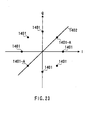
- FIG.23 is a signal space diagram according to a ⁇ /4-shift DQPSK (Differential Quadrature Phase Shift Keying) modulation type on the in-phase I - quadrature Q plane and shows a pilot symbol signal point and signal points of each one symbol immediately before and after the pilot symbol.
- reference codes 1401 and 1401-A indicate signal points according to a ⁇ /4-shift DQPSK modulation type, and especially reference codes 1401-A indicate signal points of each one symbol immediately before and after the pilot symbol.
- Reference code 1402 is a virtual line connecting the pilot symbol signal point and the origin.
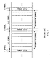
- FIG.24 shows a frame configuration example of ⁇ /4-shift DQPSK modulation symbols and pilot symbols.
- Reference code 301 indicates one symbol immediately before the pilot symbol and reference code 302 indicates one symbol immediately after the pilot symbol.
- FIG.23 shows the locations of signal points 1401 and 1401-A according to the ⁇ /4-shift DQPSK modulation type on the in-phase I - quadrature Q plane, pilot symbol signal point 1401-A and signal points 1401-A of each one symbol immediately before and after the pilot symbol.
- Two signal points 1401-A of each one symbol immediately before and after the pilot symbol are placed on virtual line 1402 connecting pilot symbol signal point 1401-A and the origin.
- FIG.24 shows a frame configuration example of ⁇ /4-shift DQPSK modulation symbols and pilot symbols.
- Reference code 301 indicates one symbol immediately before the pilot symbol and reference code 302 indicates one symbol immediately after the pilot symbol.
- the present embodiment demonstrates the effects shown in FIG.6B and FIG.6C, making it possible to suppress deterioration of the accuracy in estimating the reference phase and the amount of frequency offset by the pilot symbol. This improves the bit error rate characteristic in the signal to noise ratio during detection of the reception signal.
- pilot symbol signal point and signal points of each one symbol immediately before and after the pilot symbol on the in-phase I and quadrature Q plane are not limited to FIG.23.
- frame configuration is not limited to FIG.24.
- the digital wireless communication apparatus places two signal points of each one symbol immediately before and after the pilot symbol on a virtual line connecting the origin and pilot symbol signal point on the in-phase - quadrature plane, according to the ⁇ /4-shift DQPSK modulation type in which one pilot symbol is inserted for every 3 or more symbols, and in this way can suppress deterioration of the accuracy in estimating the reference phase and the amount of frequency offset by the pilot symbol in quasi-coherent detection of symbols whose symbol synchronization is not completely established. This improves the bit error rate characteristic in the signal to noise ratio.
- FIG.25 shows a trail of the I component and Q component of a 16QAM quadrature baseband signal on the I-Q plane.
- the available power amplifier is determined by the maximum value of I 2 +Q 2 , max (I 2 + Q 2 ), and average value, ave (I 2 + Q 2 ).
- FIG.26 is a diagram showing an input/output characteristic of the power amplifier.
- reference code 1501 indicates a characteristic curve of a power amplifier with large output power
- reference code 1502 indicates a characteristic curve of a power amplifier with small output power
- reference code 1503 indicates average output power
- reference code 1504 indicates a modulation type with small variation of I 2 + Q 2
- reference code 1505 indicates a modulation type with large variation of I 2 + Q 2 .
- the power amplifier with the characteristic of reference code 1501 has larger power consumption than the power amplifier with the characteristic of reference code 1502.
- the modulation type with a smaller maximum value of I 2 + Q 2 , max (I 2 + Q 2 ) can use the power amplifier with smaller power consumption.
- the present embodiment increases the distance of the pilot symbol from the origin without increasing the maximum value of I 2 + Q 2 , max (I 2 + Q 2 ), on the I-Q plane. This makes it possible to improve the bit error rate in the receiver without increasing power consumption of the power amplifier of the transmitter.
- the method of improving the bit error rate in the receiver without increasing power consumption of the power amplifier of the transmitter in the present embodiment is explained taking as an example the case where a 16QAM system is used as the modulation type.
- the maximum value of I 2 + Q 2 , max (I 2 + Q 2 ), according to the 16QAM system comes to the position indicated by reference code 1601 on its way from signal point A to signal point A.
- the amplitude at the pilot symbol signal point is greater than the maximum amplitude at multivalue modulation signal points on the I-Q plane. Furthermore, since the amplitude at the pilot signal symbol point is increased, it is possible to improve the accuracy in estimating the amount of amplitude distortion and the amount of frequency offset on the receiving side. As a result, it is possible to improve the bit error rate characteristic.
- I QAM r ⁇ 2 m - 1 ⁇ a 1 + 2 m - 2 ⁇ a 2 + ⁇ + 2 0 ⁇ a m
- Q QAM r ⁇ 2 m - 1 ⁇ b 1 + 2 m - 2 ⁇ b 2 + ⁇ + 2 0 ⁇ b m
- m is an integer
- (a1, b1), (a2, b2), ..., (am, bm) are binary codes of 1, -1
- r is a constant.
- Two or more signal points 503 of each one symbol immediately before and after the pilot symbol are placed on virtual line 504 connecting pilot symbol signal point 502 and the origin.
- the pilot symbol transitions on a straight line connecting the pilot symbol and the origin on the in-phase I - quadrature Q plane, and therefore it is possible to suppress deterioration of the accuracy in estimating the reference phase and the amount of frequency offset by the pilot symbol. This improves the bit error rate characteristic in the signal to noise ratio during detection of the reception signal.
- a maximum value of the multivalue QAM signal point power on the in-phase I - quadrature Q plane is a and the pilot symbol signal point power on the in-phase I - quadrature Q plane is b
- maintaining b>a makes it possible to improve the accuracy in estimating amplitude distortion by the amplitude distortion estimating section and the accuracy in estimating the amount of frequency offset by the frequency offset amount estimating section on the receiving side without deteriorating the power efficiency of the power amplifier on the transmitting side as described above. This improves the bit error rate characteristic in the signal to noise ratio during detection of the reception signal.
- the locations of the pilot symbol signal point and signal points of each one symbol immediately before and after the pilot symbol on the in-phase I - quadrature Q plane are not limited to FIG.9, but greater effects are obtained especially when the pilot symbol signal point is placed on the axis.
- the frame configuration is not limited to FIG.10.
- Equation 2 the frequency character of the route roll-off filter, which is a band limiting filter, is as shown in Equation 2 below.
- changing the roll-off factor from 0.1 to 0.4 and setting the signal point amplitude of the pilot symbol to a value greater than 1.0 time and smaller than 1.6 times the maximum signal point amplitude according to the multivalue QAM system can improve the accuracy in estimating the amount of frequency offset and the amount of amplitude distortion when carrying out quasi-coherent detection. This results in a greater effect of improving the bit error rate characteristic in the signal to noise ratio.
- Equation 2 ⁇ is frequency in radian, ⁇ is roll-off factor, ⁇ 0 is Nyquist frequency in radian and H ( ⁇ ) is amplitude characteristic of the route roll-off filter.
- H ⁇ ⁇ 1 1 2 ⁇ 1 - sin ⁇ 2 ⁇ ⁇ 0 ⁇ ⁇ - ⁇ 0 0 ⁇ ⁇ ⁇ 0 ⁇ 1 - ⁇ ⁇ 0 ⁇ 1 - ⁇ ⁇ ⁇ ⁇ 0 ⁇ 1 + ⁇ ⁇ ⁇ ⁇ 0 ⁇ 1 + ⁇ ⁇ ⁇ 0 ⁇ 1 - ⁇
- the present embodiment explains the multivalue QAM system as an example of a multivalue modulation type with 8 or more values, but the multivalue modulation type with 8 or more values is not limited to this. Moreover, a 64QAM system, 32QAM system, 16QAM system, 8PSK modulation type and QPSK modulation type can also produce effects similar to those of the multivalue QAM system.
- the digital wireless communication apparatus places two or more signal points of each one symbol immediately before and after the pilot symbol on a virtual line connecting the origin and pilot symbol signal point on the in-phase - quadrature plane, in the multivalue modulation type with 8 or more values in which one pilot symbol is inserted for every 3 or more symbols and increases the amplitude at the pilot symbol signal point more than the maximum amplitude at signal points according to the multivalue modulation type with 8 or more values.
- the present invention differentiates the modulation type immediately before and after the pilot symbol from the modulation type of the pilot symbol, and therefore can suppress deterioration of the accuracy in estimating the reference phase and the amount of frequency offset by the pilot symbol in quasi-coherent detection of symbols whose symbol synchronization is not completely established, improve the bit error rate characteristic in the signal to noise ratio.
- the present invention can further improve the bit error rate characteristic in the signal to noise ratio without deteriorating the power efficiency of the power amplifier on the transmitting side, by increasing the amplitude at the pilot symbol signal point more than the maximum amplitude at signal points according to the multivalue modulation type.
- Embodiments 1 to 9 can be implemented in a variety of combinations thereof as appropriate.
Priority Applications (5)
| Application Number | Priority Date | Filing Date | Title |
|---|---|---|---|
| EP10012929.5A EP2262162B1 (fr) | 1999-01-19 | 2000-01-17 | Dispositif et procédé communication numérique sans fil |
| EP10012919.6A EP2262161B1 (fr) | 1999-01-19 | 2000-01-17 | Dispositif et procédé communication numérique sans fil |
| EP10012917.0A EP2262159B1 (fr) | 1999-01-19 | 2000-01-17 | Dispositif et procédé communication numérique sans fil |
| EP10012918.8A EP2262160B1 (fr) | 1999-01-19 | 2000-01-17 | Dispositif et procédé de communication numérique sans fil |
| EP09008471A EP2101440B1 (fr) | 1999-01-19 | 2000-01-17 | Appareil et procédé pour communications numériques sans fil |
Applications Claiming Priority (3)
| Application Number | Priority Date | Filing Date | Title |
|---|---|---|---|
| JP1014699 | 1999-01-19 | ||
| JP21326499 | 1999-07-28 | ||
| EP00100828A EP1022874B1 (fr) | 1999-01-19 | 2000-01-17 | Dispositif et procédé de communication numérique sans fil |
Related Parent Applications (2)
| Application Number | Title | Priority Date | Filing Date |
|---|---|---|---|
| EP00100828.3 Division | 2000-01-17 | ||
| EP00100828A Division EP1022874B1 (fr) | 1999-01-19 | 2000-01-17 | Dispositif et procédé de communication numérique sans fil |
Related Child Applications (6)
| Application Number | Title | Priority Date | Filing Date |
|---|---|---|---|
| EP09008471A Division EP2101440B1 (fr) | 1999-01-19 | 2000-01-17 | Appareil et procédé pour communications numériques sans fil |
| EP10012929.5A Division EP2262162B1 (fr) | 1999-01-19 | 2000-01-17 | Dispositif et procédé communication numérique sans fil |
| EP10012917.0A Division EP2262159B1 (fr) | 1999-01-19 | 2000-01-17 | Dispositif et procédé communication numérique sans fil |
| EP10012919.6A Division EP2262161B1 (fr) | 1999-01-19 | 2000-01-17 | Dispositif et procédé communication numérique sans fil |
| EP10012918.8A Division EP2262160B1 (fr) | 1999-01-19 | 2000-01-17 | Dispositif et procédé de communication numérique sans fil |
| EP09008471.6 Division-Into | 2009-06-29 |
Publications (3)
| Publication Number | Publication Date |
|---|---|
| EP1843506A2 true EP1843506A2 (fr) | 2007-10-10 |
| EP1843506A3 EP1843506A3 (fr) | 2007-10-31 |
| EP1843506B1 EP1843506B1 (fr) | 2010-06-02 |
Family
ID=26345354
Family Applications (7)
| Application Number | Title | Priority Date | Filing Date |
|---|---|---|---|
| EP00100828A Expired - Lifetime EP1022874B1 (fr) | 1999-01-19 | 2000-01-17 | Dispositif et procédé de communication numérique sans fil |
| EP07014948A Expired - Lifetime EP1843506B1 (fr) | 1999-01-19 | 2000-01-17 | Appareil et procédé pour communications numériques sans fil |
| EP10012918.8A Expired - Lifetime EP2262160B1 (fr) | 1999-01-19 | 2000-01-17 | Dispositif et procédé de communication numérique sans fil |
| EP10012919.6A Expired - Lifetime EP2262161B1 (fr) | 1999-01-19 | 2000-01-17 | Dispositif et procédé communication numérique sans fil |
| EP10012917.0A Expired - Lifetime EP2262159B1 (fr) | 1999-01-19 | 2000-01-17 | Dispositif et procédé communication numérique sans fil |
| EP09008471A Expired - Lifetime EP2101440B1 (fr) | 1999-01-19 | 2000-01-17 | Appareil et procédé pour communications numériques sans fil |
| EP10012929.5A Expired - Lifetime EP2262162B1 (fr) | 1999-01-19 | 2000-01-17 | Dispositif et procédé communication numérique sans fil |
Family Applications Before (1)
| Application Number | Title | Priority Date | Filing Date |
|---|---|---|---|
| EP00100828A Expired - Lifetime EP1022874B1 (fr) | 1999-01-19 | 2000-01-17 | Dispositif et procédé de communication numérique sans fil |
Family Applications After (5)
| Application Number | Title | Priority Date | Filing Date |
|---|---|---|---|
| EP10012918.8A Expired - Lifetime EP2262160B1 (fr) | 1999-01-19 | 2000-01-17 | Dispositif et procédé de communication numérique sans fil |
| EP10012919.6A Expired - Lifetime EP2262161B1 (fr) | 1999-01-19 | 2000-01-17 | Dispositif et procédé communication numérique sans fil |
| EP10012917.0A Expired - Lifetime EP2262159B1 (fr) | 1999-01-19 | 2000-01-17 | Dispositif et procédé communication numérique sans fil |
| EP09008471A Expired - Lifetime EP2101440B1 (fr) | 1999-01-19 | 2000-01-17 | Appareil et procédé pour communications numériques sans fil |
| EP10012929.5A Expired - Lifetime EP2262162B1 (fr) | 1999-01-19 | 2000-01-17 | Dispositif et procédé communication numérique sans fil |
Country Status (4)
| Country | Link |
|---|---|
| US (11) | US6608868B1 (fr) |
| EP (7) | EP1022874B1 (fr) |
| CN (3) | CN1171424C (fr) |
| DE (2) | DE60044517D1 (fr) |
Cited By (1)
| Publication number | Priority date | Publication date | Assignee | Title |
|---|---|---|---|---|
| CN101808067A (zh) * | 2010-03-04 | 2010-08-18 | 清华大学 | 利用差分数据作为导频的ofdm信号收发方法及其装置 |
Families Citing this family (22)
| Publication number | Priority date | Publication date | Assignee | Title |
|---|---|---|---|---|
| US6608868B1 (en) * | 1999-01-19 | 2003-08-19 | Matsushita Electric Industrial Co., Ltd. | Apparatus and method for digital wireless communications |
| EP1324624A4 (fr) | 2000-08-31 | 2007-11-07 | Huawei Tech Co Ltd | Procede de modulation par deplacement de 8 phases (8mdp) et dispositif associe |
| US7023933B2 (en) | 2000-10-20 | 2006-04-04 | Matsushita Electric Industrial Co., Ltd. | Radio communication apparatus |
| US7599627B2 (en) | 2001-05-31 | 2009-10-06 | Teradvance Communications, Llc | Method and system for a polarization mode dispersion tolerant optical homodyne detection system with optimized transmission modulation |
| JP3997890B2 (ja) | 2001-11-13 | 2007-10-24 | 松下電器産業株式会社 | 送信方法及び送信装置 |
| JP3840435B2 (ja) * | 2002-07-05 | 2006-11-01 | 松下電器産業株式会社 | 無線通信基地局装置、無線通信移動局装置および無線通信方法 |
| JP2004153466A (ja) * | 2002-10-29 | 2004-05-27 | Matsushita Electric Ind Co Ltd | 受信方法、受信装置及び無線伝送システム |
| US7359445B2 (en) * | 2003-06-27 | 2008-04-15 | Nokia Corporation | System, method and computer program product for demodulating quadrature amplitude modulated signals based upon a speed of a receiver |
| US7289551B2 (en) * | 2003-06-27 | 2007-10-30 | Nokia Siemens Corporation | System, method and computer program product for demodulating quadrature amplitude modulated signals |
| US7680278B2 (en) * | 2004-02-04 | 2010-03-16 | Microsoft Corporation | Domino scheme for wireless cryptographic communication and communication method incorporating same |
| US7627054B2 (en) * | 2004-04-26 | 2009-12-01 | Vicente Diaz Fuente | Device and method for improving the signal to noise ratio by means of complementary sequences |
| US7826555B2 (en) | 2005-08-24 | 2010-11-02 | Panasonic Corporation | MIMO-OFDM transmission device and MIMO-OFDM transmission method |
| GB2443239A (en) * | 2006-10-24 | 2008-04-30 | Stream Technology Ltd M | Telecommunication system with simplified receiver |
| US8582543B2 (en) * | 2007-03-15 | 2013-11-12 | Panasonic Corporation | Wireless communication device and access point connection method |
| US7652980B2 (en) * | 2007-11-02 | 2010-01-26 | Nokia Corporation | Orthogonal frequency division multiplexing synchronization |
| CN101646232B (zh) * | 2008-07-18 | 2014-07-02 | 美满电子科技(上海)有限公司 | 频偏估计方法、装置以及通信设备 |
| CN102946368B (zh) * | 2012-12-11 | 2016-03-23 | 西安电子科技大学 | 多径衰落信道下含有频偏和相偏的数字调制信号识别方法 |
| WO2014167861A1 (fr) * | 2013-04-12 | 2014-10-16 | パナソニック インテレクチュアル プロパティ コーポレーション オブ アメリカ | Procédé de transmission |
| EP3223446A1 (fr) * | 2016-03-22 | 2017-09-27 | Xieon Networks S.à r.l. | Procédé de protection d'une liaison dans un réseau optique |
| CN110224807A (zh) * | 2019-05-28 | 2019-09-10 | 湖北三江航天险峰电子信息有限公司 | 一种基于agc频偏预估的载波同步方法及系统 |
| CN110324269B (zh) * | 2019-06-24 | 2022-01-04 | 西安空间无线电技术研究所 | 一种高速解调器的符号同步系统及实现方法 |
| WO2021021007A1 (fr) * | 2019-07-29 | 2021-02-04 | Telefonaktiebolaget Lm Ericsson (Publ) | Procédé et appareil de modulation adaptative assistée par phase |
Citations (1)
| Publication number | Priority date | Publication date | Assignee | Title |
|---|---|---|---|---|
| EP0734132A2 (fr) | 1995-03-23 | 1996-09-25 | Kabushiki Kaisha Toshiba | Structure de signal pour modulation multiporteuse, réduisant le besoin de capacité additionnelle |
Family Cites Families (31)
| Publication number | Priority date | Publication date | Assignee | Title |
|---|---|---|---|---|
| US5519730A (en) * | 1990-06-12 | 1996-05-21 | Jasper; Steven C. | Communication signal having a time domain pilot component |
| US5381449A (en) * | 1990-06-12 | 1995-01-10 | Motorola, Inc. | Peak to average power ratio reduction methodology for QAM communications systems |
| US5241544A (en) * | 1991-11-01 | 1993-08-31 | Motorola, Inc. | Multi-channel tdm communication system slot phase correction |
| US5425027A (en) * | 1993-01-04 | 1995-06-13 | Com21, Inc. | Wide area fiber and TV cable fast packet cell network |
| US5414734A (en) * | 1993-01-06 | 1995-05-09 | Glenayre Electronics, Inc. | Compensation for multi-path interference using pilot symbols |
| JPH06268574A (ja) * | 1993-03-11 | 1994-09-22 | Hitachi Ltd | セルラ移動通信システム |
| US5870393A (en) * | 1995-01-20 | 1999-02-09 | Hitachi, Ltd. | Spread spectrum communication system and transmission power control method therefor |
| US5533048A (en) * | 1993-07-28 | 1996-07-02 | Celeritas Technologies, Ltd. | Apparatus and method for compensating for limiter induced non-linear distortion in a wireless data communication system |
| JP3485117B2 (ja) * | 1993-09-10 | 2004-01-13 | ドイチェ トムソン−ブラント ゲーエムベーハー | Ofdm方式の基準信号の伝送方法 |
| KR0145047B1 (ko) * | 1993-09-28 | 1998-07-15 | 김광호 | 디지탈신호 기록/재생장치의 변조 및 복조회로 |
| JP3463828B2 (ja) * | 1994-11-21 | 2003-11-05 | ソニー株式会社 | 送信機 |
| US5659578A (en) * | 1994-11-23 | 1997-08-19 | At&T Wireless Services, Inc. | High rate Reed-Solomon concatenated trellis coded 16 star QAM system for transmission of data over cellular mobile radio |
| US5659728A (en) * | 1994-12-30 | 1997-08-19 | International Business Machines Corporation | System and method for generating uniqueness information for optimizing an SQL query |
| JP2863993B2 (ja) * | 1995-06-22 | 1999-03-03 | 松下電器産業株式会社 | Cdma無線多重送信装置およびcdma無線多重伝送装置およびcdma無線受信装置およびcdma無線多重送信方法 |
| JP3125644B2 (ja) * | 1995-09-13 | 2001-01-22 | 松下電器産業株式会社 | 復調装置 |
| JP2903104B2 (ja) | 1995-09-22 | 1999-06-07 | 郵政省通信総合研究所長 | ディジタル移動無線通信方式 |
| JP3759233B2 (ja) * | 1996-04-19 | 2006-03-22 | ローム株式会社 | 光通信用デバイス |
| US5914959A (en) * | 1996-10-31 | 1999-06-22 | Glenayre Electronics, Inc. | Digital communications system having an automatically selectable transmission rate |
| JPH10336144A (ja) | 1997-05-29 | 1998-12-18 | Matsushita Electric Ind Co Ltd | 符号分割多元接続移動体通信装置 |
| JP3655057B2 (ja) * | 1997-07-19 | 2005-06-02 | 松下電器産業株式会社 | Cdma送信装置及びcdma送信方法 |
| US6157679A (en) * | 1997-10-17 | 2000-12-05 | Motorola, Inc. | Method of adding encryption/encoding element to the modulation/demodulation process |
| US6301237B1 (en) | 1997-12-30 | 2001-10-09 | Matsushita Electric Industrial Co., Ltd. | CDMA radio multiplex transmitting device and a CDMA radio multiplex receiving device |
| JP3166705B2 (ja) * | 1998-04-16 | 2001-05-14 | 松下電器産業株式会社 | 無線装置及び送信方法 |
| AUPP748698A0 (en) * | 1998-12-03 | 1998-12-24 | Gryffin Pty Ltd | Deflection sensors |
| US6608868B1 (en) | 1999-01-19 | 2003-08-19 | Matsushita Electric Industrial Co., Ltd. | Apparatus and method for digital wireless communications |
| JP3779092B2 (ja) * | 1999-05-12 | 2006-05-24 | 松下電器産業株式会社 | 送受信装置 |
| US6259728B1 (en) * | 1999-06-08 | 2001-07-10 | Lucent Technologies Inc. | Data communication system and method |
| JP4284773B2 (ja) * | 1999-09-07 | 2009-06-24 | ソニー株式会社 | 送信装置、受信装置、通信システム、送信方法及び通信方法 |
| US6580705B1 (en) * | 1999-10-28 | 2003-06-17 | Lucent Technologies Inc. | Signal combining scheme for wireless transmission systems having multiple modulation schemes |
| US7508842B2 (en) * | 2005-08-18 | 2009-03-24 | Motorola, Inc. | Method and apparatus for pilot signal transmission |
| US9363126B2 (en) * | 2007-12-21 | 2016-06-07 | Google Technology Holdings LLC | Method and apparatus for IFDMA receiver architecture |
-
2000
- 2000-01-14 US US09/482,892 patent/US6608868B1/en not_active Expired - Lifetime
- 2000-01-17 EP EP00100828A patent/EP1022874B1/fr not_active Expired - Lifetime
- 2000-01-17 EP EP07014948A patent/EP1843506B1/fr not_active Expired - Lifetime
- 2000-01-17 EP EP10012918.8A patent/EP2262160B1/fr not_active Expired - Lifetime
- 2000-01-17 DE DE60044517T patent/DE60044517D1/de not_active Expired - Lifetime
- 2000-01-17 DE DE60036742T patent/DE60036742T2/de not_active Expired - Lifetime
- 2000-01-17 EP EP10012919.6A patent/EP2262161B1/fr not_active Expired - Lifetime
- 2000-01-17 EP EP10012917.0A patent/EP2262159B1/fr not_active Expired - Lifetime
- 2000-01-17 EP EP09008471A patent/EP2101440B1/fr not_active Expired - Lifetime
- 2000-01-17 EP EP10012929.5A patent/EP2262162B1/fr not_active Expired - Lifetime
- 2000-01-19 CN CNB001011332A patent/CN1171424C/zh not_active Expired - Lifetime
- 2000-01-19 CN CN200410035135.8A patent/CN100544340C/zh not_active Expired - Lifetime
- 2000-01-19 CN CN200610095899.5A patent/CN1913516B/zh not_active Expired - Lifetime
-
2003
- 2003-05-02 US US10/427,992 patent/US6748023B2/en not_active Expired - Lifetime
- 2003-05-28 US US10/445,808 patent/US6738430B2/en not_active Expired - Lifetime
-
2004
- 2004-02-20 US US10/781,839 patent/US7359454B2/en not_active Expired - Lifetime
-
2007
- 2007-07-31 US US11/831,383 patent/US7492833B2/en not_active Expired - Fee Related
-
2008
- 2008-06-17 US US12/140,483 patent/US7630455B2/en not_active Expired - Fee Related
- 2008-12-29 US US12/345,297 patent/US7711064B2/en not_active Expired - Fee Related
-
2010
- 2010-03-15 US US12/724,098 patent/US7873124B2/en not_active Expired - Fee Related
- 2010-12-17 US US12/971,564 patent/US8098772B2/en not_active Expired - Fee Related
-
2011
- 2011-12-13 US US13/324,389 patent/US8442158B2/en not_active Expired - Fee Related
-
2013
- 2013-05-09 US US13/890,973 patent/US8687677B2/en not_active Expired - Fee Related
Patent Citations (1)
| Publication number | Priority date | Publication date | Assignee | Title |
|---|---|---|---|---|
| EP0734132A2 (fr) | 1995-03-23 | 1996-09-25 | Kabushiki Kaisha Toshiba | Structure de signal pour modulation multiporteuse, réduisant le besoin de capacité additionnelle |
Cited By (2)
| Publication number | Priority date | Publication date | Assignee | Title |
|---|---|---|---|---|
| CN101808067A (zh) * | 2010-03-04 | 2010-08-18 | 清华大学 | 利用差分数据作为导频的ofdm信号收发方法及其装置 |
| CN101808067B (zh) * | 2010-03-04 | 2012-11-14 | 清华大学 | 利用差分数据作为导频的ofdm信号收发方法及其装置 |
Also Published As
Similar Documents
| Publication | Publication Date | Title |
|---|---|---|
| US8687677B2 (en) | Method for digital wireless communications | |
| US10498571B2 (en) | Transmission apparatus, reception apparatus and digital radio communication method | |
| EP0951151B1 (fr) | Technique de transmission de signal pilote et système de communication numérique utilisant une telle technique | |
| JP3563345B2 (ja) | 送信方法及び送信装置 | |
| JP3611995B2 (ja) | ディジタル無線通信装置及び方法 | |
| JP3980017B2 (ja) | 送信装置及び通信方法 | |
| JP2001197138A (ja) | 無線装置及び送信方法 |
Legal Events
| Date | Code | Title | Description |
|---|---|---|---|
| PUAI | Public reference made under article 153(3) epc to a published international application that has entered the european phase |
Free format text: ORIGINAL CODE: 0009012 |
|
| PUAL | Search report despatched |
Free format text: ORIGINAL CODE: 0009013 |
|
| 17P | Request for examination filed |
Effective date: 20070731 |
|
| AC | Divisional application: reference to earlier application |
Ref document number: 1022874 Country of ref document: EP Kind code of ref document: P |
|
| AK | Designated contracting states |
Kind code of ref document: A2 Designated state(s): DE FR GB |
|
| AK | Designated contracting states |
Kind code of ref document: A3 Designated state(s): DE FR GB |
|
| RIC1 | Information provided on ipc code assigned before grant |
Ipc: H04L 7/06 20060101AFI20070922BHEP Ipc: H04L 27/34 20060101ALI20070922BHEP |
|
| RIN1 | Information on inventor provided before grant (corrected) |
Inventor name: MATSUOKA, AKIHIKO Inventor name: ORIHASHI, MASAYUKIC/O MATSUSHITA EL.IND.CO.LTD. Inventor name: TAKABAYASHI, SHINICHIRO Inventor name: MURAKAMI, YUTAKA |
|
| RIN1 | Information on inventor provided before grant (corrected) |
Inventor name: TAKABAYASHI, SHINICHIROC/O MATSUSHITA ELECTRIC IND Inventor name: MATSUOKA, AKIHIKO Inventor name: ORIHASHI, MASAYUKIC/O MATSUSHITA EL.IND.CO.LTD. Inventor name: MURAKAMI, YUTAKAC/O MATSUSHITA ELECTRIC IND. CO., |
|
| AKX | Designation fees paid |
Designated state(s): DE FR GB |
|
| GRAP | Despatch of communication of intention to grant a patent |
Free format text: ORIGINAL CODE: EPIDOSNIGR1 |
|
| RAP1 | Party data changed (applicant data changed or rights of an application transferred) |
Owner name: PANASONIC CORPORATION |
|
| GRAS | Grant fee paid |
Free format text: ORIGINAL CODE: EPIDOSNIGR3 |
|
| 17Q | First examination report despatched |
Effective date: 20090302 |
|
| GRAA | (expected) grant |
Free format text: ORIGINAL CODE: 0009210 |
|
| AC | Divisional application: reference to earlier application |
Ref document number: 1022874 Country of ref document: EP Kind code of ref document: P |
|
| AK | Designated contracting states |
Kind code of ref document: B1 Designated state(s): DE FR GB |
|
| REG | Reference to a national code |
Ref country code: GB Ref legal event code: FG4D |
|
| REF | Corresponds to: |
Ref document number: 60044517 Country of ref document: DE Date of ref document: 20100715 Kind code of ref document: P |
|
| PLBE | No opposition filed within time limit |
Free format text: ORIGINAL CODE: 0009261 |
|
| STAA | Information on the status of an ep patent application or granted ep patent |
Free format text: STATUS: NO OPPOSITION FILED WITHIN TIME LIMIT |
|
| 26N | No opposition filed |
Effective date: 20110303 |
|
| REG | Reference to a national code |
Ref country code: DE Ref legal event code: R097 Ref document number: 60044517 Country of ref document: DE Effective date: 20110302 |
|
| REG | Reference to a national code |
Ref country code: GB Ref legal event code: 732E Free format text: REGISTERED BETWEEN 20140612 AND 20140618 |
|
| REG | Reference to a national code |
Ref country code: DE Ref legal event code: R082 Ref document number: 60044517 Country of ref document: DE Representative=s name: GRUENECKER, KINKELDEY, STOCKMAIR & SCHWANHAEUS, DE |
|
| REG | Reference to a national code |
Ref country code: DE Ref legal event code: R082 Ref document number: 60044517 Country of ref document: DE Representative=s name: GRUENECKER, KINKELDEY, STOCKMAIR & SCHWANHAEUS, DE Effective date: 20140711 Ref country code: DE Ref legal event code: R081 Ref document number: 60044517 Country of ref document: DE Owner name: PANASONIC INTELLECTUAL PROPERTY CORPORATION OF, US Free format text: FORMER OWNER: PANASONIC CORPORATION, KADOMA-SHI, OSAKA, JP Effective date: 20140711 Ref country code: DE Ref legal event code: R082 Ref document number: 60044517 Country of ref document: DE Representative=s name: GRUENECKER PATENT- UND RECHTSANWAELTE PARTG MB, DE Effective date: 20140711 Ref country code: DE Ref legal event code: R081 Ref document number: 60044517 Country of ref document: DE Owner name: SUN PATENT TRUST, NEW YORK, US Free format text: FORMER OWNER: PANASONIC CORPORATION, KADOMA-SHI, OSAKA, JP Effective date: 20140711 |
|
| REG | Reference to a national code |
Ref country code: FR Ref legal event code: TP Owner name: PANASONIC INTELLECTUAL PROPERTY CORPORATION OF, US Effective date: 20140722 |
|
| REG | Reference to a national code |
Ref country code: FR Ref legal event code: PLFP Year of fee payment: 17 |
|
| REG | Reference to a national code |
Ref country code: DE Ref legal event code: R082 Ref document number: 60044517 Country of ref document: DE Representative=s name: GRUENECKER PATENT- UND RECHTSANWAELTE PARTG MB, DE Ref country code: DE Ref legal event code: R081 Ref document number: 60044517 Country of ref document: DE Owner name: SUN PATENT TRUST, NEW YORK, US Free format text: FORMER OWNER: PANASONIC INTELLECTUAL PROPERTY CORPORATION OF AMERICA, TORRANCE, CALIF., US |
|
| REG | Reference to a national code |
Ref country code: FR Ref legal event code: PLFP Year of fee payment: 18 |
|
| REG | Reference to a national code |
Ref country code: FR Ref legal event code: TP Owner name: SUN PATENT TRUST, US Effective date: 20161221 |
|
| REG | Reference to a national code |
Ref country code: FR Ref legal event code: TP Owner name: SUN PATENT TRUST, US Effective date: 20170411 |
|
| REG | Reference to a national code |
Ref country code: FR Ref legal event code: PLFP Year of fee payment: 19 |
|
| PGFP | Annual fee paid to national office [announced via postgrant information from national office to epo] |
Ref country code: FR Payment date: 20181213 Year of fee payment: 20 |
|
| PGFP | Annual fee paid to national office [announced via postgrant information from national office to epo] |
Ref country code: GB Payment date: 20190116 Year of fee payment: 20 Ref country code: DE Payment date: 20190102 Year of fee payment: 20 |
|
| REG | Reference to a national code |
Ref country code: GB Ref legal event code: 732E Free format text: REGISTERED BETWEEN 20190530 AND 20190605 |
|
| REG | Reference to a national code |
Ref country code: DE Ref legal event code: R071 Ref document number: 60044517 Country of ref document: DE |
|
| REG | Reference to a national code |
Ref country code: GB Ref legal event code: PE20 Expiry date: 20200116 |
|
| PG25 | Lapsed in a contracting state [announced via postgrant information from national office to epo] |
Ref country code: GB Free format text: LAPSE BECAUSE OF EXPIRATION OF PROTECTION Effective date: 20200116 |