EP1842776A2 - Vorrichtung zur Verpackung von Ablagen mit Produkten in einer modifizierten Atmosphäre - Google Patents
Vorrichtung zur Verpackung von Ablagen mit Produkten in einer modifizierten Atmosphäre Download PDFInfo
- Publication number
- EP1842776A2 EP1842776A2 EP07104527A EP07104527A EP1842776A2 EP 1842776 A2 EP1842776 A2 EP 1842776A2 EP 07104527 A EP07104527 A EP 07104527A EP 07104527 A EP07104527 A EP 07104527A EP 1842776 A2 EP1842776 A2 EP 1842776A2
- Authority
- EP
- European Patent Office
- Prior art keywords
- tray
- film
- drawer
- envisaged
- edge
- Prior art date
- Legal status (The legal status is an assumption and is not a legal conclusion. Google has not performed a legal analysis and makes no representation as to the accuracy of the status listed.)
- Granted
Links
- 238000004806 packaging method and process Methods 0.000 title claims abstract description 32
- 238000003466 welding Methods 0.000 claims abstract description 44
- 238000005520 cutting process Methods 0.000 claims abstract description 19
- 238000003825 pressing Methods 0.000 claims abstract description 12
- 230000000284 resting effect Effects 0.000 claims abstract description 4
- 230000004888 barrier function Effects 0.000 claims abstract 6
- 238000011144 upstream manufacturing Methods 0.000 claims description 13
- 239000000463 material Substances 0.000 claims description 9
- 238000000034 method Methods 0.000 claims description 9
- 238000010008 shearing Methods 0.000 claims description 8
- 239000002699 waste material Substances 0.000 claims description 8
- 230000003750 conditioning effect Effects 0.000 claims description 6
- 230000000717 retained effect Effects 0.000 claims description 6
- 239000000853 adhesive Substances 0.000 claims description 4
- 230000001070 adhesive effect Effects 0.000 claims description 4
- 238000003860 storage Methods 0.000 claims description 4
- 238000012546 transfer Methods 0.000 claims description 4
- 238000000605 extraction Methods 0.000 claims description 3
- 238000003801 milling Methods 0.000 claims description 3
- 230000005484 gravity Effects 0.000 claims description 2
- 239000000523 sample Substances 0.000 claims description 2
- 230000003068 static effect Effects 0.000 claims description 2
- 229920001169 thermoplastic Polymers 0.000 claims description 2
- 239000004416 thermosoftening plastic Substances 0.000 claims description 2
- 230000000694 effects Effects 0.000 claims 3
- 239000012080 ambient air Substances 0.000 claims 2
- 238000009825 accumulation Methods 0.000 claims 1
- 239000003570 air Substances 0.000 claims 1
- 239000004033 plastic Substances 0.000 claims 1
- DOSMHBDKKKMIEF-UHFFFAOYSA-N 2-[3-(diethylamino)-6-diethylazaniumylidenexanthen-9-yl]-5-[3-[3-[4-(1-methylindol-3-yl)-2,5-dioxopyrrol-3-yl]indol-1-yl]propylsulfamoyl]benzenesulfonate Chemical compound C1=CC(=[N+](CC)CC)C=C2OC3=CC(N(CC)CC)=CC=C3C(C=3C(=CC(=CC=3)S(=O)(=O)NCCCN3C4=CC=CC=C4C(C=4C(NC(=O)C=4C=4C5=CC=CC=C5N(C)C=4)=O)=C3)S([O-])(=O)=O)=C21 DOSMHBDKKKMIEF-UHFFFAOYSA-N 0.000 description 9
- 238000011010 flushing procedure Methods 0.000 description 6
- 239000007789 gas Substances 0.000 description 2
- 238000010438 heat treatment Methods 0.000 description 2
- 238000007664 blowing Methods 0.000 description 1
- 238000004891 communication Methods 0.000 description 1
- 230000001143 conditioned effect Effects 0.000 description 1
- 230000008878 coupling Effects 0.000 description 1
- 238000010168 coupling process Methods 0.000 description 1
- 238000005859 coupling reaction Methods 0.000 description 1
- 230000001419 dependent effect Effects 0.000 description 1
- 238000007599 discharging Methods 0.000 description 1
- 229920001971 elastomer Polymers 0.000 description 1
- 239000000806 elastomer Substances 0.000 description 1
- 239000004794 expanded polystyrene Substances 0.000 description 1
- 235000013305 food Nutrition 0.000 description 1
- 238000003780 insertion Methods 0.000 description 1
- 230000037431 insertion Effects 0.000 description 1
- 238000004519 manufacturing process Methods 0.000 description 1
- 239000000203 mixture Substances 0.000 description 1
- 238000000465 moulding Methods 0.000 description 1
- 238000011160 research Methods 0.000 description 1
- 229920006395 saturated elastomer Polymers 0.000 description 1
- 238000007789 sealing Methods 0.000 description 1
- 239000007787 solid Substances 0.000 description 1
Images

Classifications
-
- B—PERFORMING OPERATIONS; TRANSPORTING
- B65—CONVEYING; PACKING; STORING; HANDLING THIN OR FILAMENTARY MATERIAL
- B65B—MACHINES, APPARATUS OR DEVICES FOR, OR METHODS OF, PACKAGING ARTICLES OR MATERIALS; UNPACKING
- B65B31/00—Packaging articles or materials under special atmospheric or gaseous conditions; Adding propellants to aerosol containers
- B65B31/04—Evacuating, pressurising or gasifying filled containers or wrappers by means of nozzles through which air or other gas, e.g. an inert gas, is withdrawn or supplied
- B65B31/043—Evacuating, pressurising or gasifying filled containers or wrappers by means of nozzles through which air or other gas, e.g. an inert gas, is withdrawn or supplied the nozzles acting horizontally between an upper and a lower part of the container or wrapper, e.g. between container and lid
-
- B—PERFORMING OPERATIONS; TRANSPORTING
- B65—CONVEYING; PACKING; STORING; HANDLING THIN OR FILAMENTARY MATERIAL
- B65B—MACHINES, APPARATUS OR DEVICES FOR, OR METHODS OF, PACKAGING ARTICLES OR MATERIALS; UNPACKING
- B65B31/00—Packaging articles or materials under special atmospheric or gaseous conditions; Adding propellants to aerosol containers
- B65B31/02—Filling, closing, or filling and closing, containers or wrappers in chambers maintained under vacuum or superatmospheric pressure or containing a special atmosphere, e.g. of inert gas
- B65B31/025—Filling, closing, or filling and closing, containers or wrappers in chambers maintained under vacuum or superatmospheric pressure or containing a special atmosphere, e.g. of inert gas specially adapted for rigid or semi-rigid containers
- B65B31/028—Filling, closing, or filling and closing, containers or wrappers in chambers maintained under vacuum or superatmospheric pressure or containing a special atmosphere, e.g. of inert gas specially adapted for rigid or semi-rigid containers closed by a lid sealed to the upper rim of the container, e.g. tray-like container
Definitions
- the invention relates to the machine and to the method described in the document WO 2006/084807 (A1 ), which concerns a machine and a method for packaging food products inside tubs or trays which are closed sealingly at the top with a thermoplastic film, in particular for packaging trays containing the product in a modified atmosphere.
- this method and with this machine it has been possible to produce packages containing products in a modified atmosphere, with surprising results when tubs or trays made of expanded polystyrene suitably provided for such a type of gas-tight packaging are used, since the said trays have their upper edge which is sufficiently elastically yielding to be suitable for undergoing a process involving continuous welding with the covering film by means of a welding roller which applies onto the tray itself and onto the film the appropriate pressure and heating values.
- the trays are transparent and made, for example, of PE or PET
- the aforementioned continuous heat-welding process performed by means of a roller has posed production difficulties owing to the relative rigidity of the edge of these trays, even though sufficiently elastically yielding material was placed under this edge.
- the modified atmosphere is created inside the tray without the use of vacuum pumps in order to eliminate firstly the air present in the said product-containing tray, but by means of a so-called flushing operation which consists in introducing into the tray the modified atmosphere using blowing means and providing means which allow removal of the air for its replacement with the new conservation atmosphere such that, when the tray is sealingly closed with the film, the latter traps this new atmosphere inside the said tray.
- the invention intends to overcome this problem and other problems of the prior art, by means of an apparatus as claimed in Claim 1 and the subsequent dependent claims, based on the following proposed solution.
- the upper edge of the tray rests on an annular rim which is solid and horizontal and which reproduces the form thereof and is preferably lined with a suitable material which is sufficiently elastic and non-adhesive, so as to meet the moulding requirements of a welding die and ensure a good sealed joint with the said edge.
- This rim delimits internally the opening of a horizontal drawer inside which the body of the tray with the product inside it may be seated and, around this rim, the drawer has a continuous annular channel, the outer shoulder of which has a height greater than that of the inner shoulder and opens out on an upper side of the said drawer, which for this reason is at a greater height than that of the said rim and the upper edge of the tray positioned thereon.
- an intact length of film unwound from a supply reel and connected at the other end to a storage spool is positioned on the upper side of the drawer and then foil-pressing means are envisaged for pressing, when operated, the film onto the upper side of the said drawer, at a due distance from the outer shoulder of the said annular channel, so as to form a packaging chamber which is substantially closed with respect to the outside and is defined at the bottom by the tray, along the sides by the said annular channel and at the top by the covering film which is at a due distance from the edge of the tray and which allows communication between the latter and the annular channel.
- This annular channel has, on at least one side and preferably on three consecutive sides, openings through which the modified atmosphere is blown in, upon operation, while on the fourth side the said annular channel has suitable discharge openings, through which the air contained inside the tray firstly passes out, pushed by the front edge of the incoming modified atmosphere, and then this modified atmosphere also partly passes out.
- the heat-welding plate also has, mounted thereon, shearing or cutting means which, after heat-welding, separate the closed tray with inside the product packaged in a modified atmosphere from the continuous film, following which the said drawer is extracted from such an apparatus, the closed tray is extracted from the said drawer and replaced with a new tray to be packaged and then the entire assembly is inserted again into the said flushing, welding and cutting station, underneath which a new length of intact film has been positioned in synchronism, while the length of film with the window resulting from the previous cycle has been moved away and stored on a suitable spool.
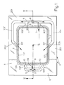
- the tray V with inside it the product P to be packaged in a modified atmosphere which usually does not project from the upper edge of the said tray, is positioned with its edge B on an annular, horizontal and flat rim 1 which is lined by a continuous and flat seal 2 made of any suitable elastomer material which has good properties in terms of elasticity, sufficient yield, strength at the welding temperature (see below) and non-adherence with respect to the material which forms the said tray V.
- the rim 1, 2 surrounds the opening 103 of a horizontal drawer 3, which opening has a form and dimensions such that it may be passed through, with play, by the body of the tray V so that the latter rests and is suspended with its edge B on the said rim 1, 2 which in turn has dimensions and a form such as to cooperate in a uniformly distributed manner with the bottom flat surface of the said edge B. It is obvious that, upon variation in the plan-view form and dimensions of the tray V, the drawer 3 with the associated parts is replaced.
- the rim 1, 2 is surrounded by a continuous annular channel 4, the outer wall 104 of which has a height greater than that of the inner wall which defines the said rim 1 and this outer wall opens out on the upper side 203 of the drawer 3, such that this side 203 is at a level suitably higher than that of the edge B of the tray resting on the said rim 1, 2.
- the upper side 203 of the drawer 3 has, formed in it, for example by means of a milling operation, at a due distance from the channel 4, a straight duct 5 which is parallel to one side of the same channel 4, for example the short side, and which continues with branches 105, 105' parallel to the consecutive sides, for example those of greater length of the said channel 4, into the middle part of which the said branches 105, 105' lead with inclined and mutually converging sections 205, 205'.
- the middle part of the channel 5 has, joined to it, in a symmetrical position, the ends of the ducts 305, 305' which also communicate with the short side of the channel 4, all of which so that, by fixing in a sealed manner onto the upper side 203 of the drawer a covering plate 6 with, in the centre, an opening 106 which leaves the channel 4 free, the end parts of the said branches 305, 305' and 205, 205' of the duct 5 open out inside the channel 4 with - for example rectangular - apertures 7 and 107 which have the same width as each other (see below).
- the top end of a vertical hole with a suitable cross-section 8 opens out in the middle part of the duct 5 and has, connected at its bottom end, the circuit for supplying the modified atmosphere at appropriate pressure values, schematically indicated by the arrow IN.
- the duct 5 is connected to the ducts 105, 105' via connected branches and the same ducts 105, 105' as well as the end ducts 205, 205' may be formed with a depth slightly increasing towards the associated discharge mouths 107, in order to compensate for the losses in head, so that gas is emitted from these mouths 107 substantially with the same flowrate and/or pressure as that which emerges from the first mouths 7.
- a duct 9 is formed, parallel to the duct 5, along the other short side of the channel 4, at a due distance from the latter, again by means of milling in the upper side of the drawer 3, said channel 9 continuing towards the said channel 4 with symmetrically arranged branches 109, 109', 109", all of which so that, owing to the presence of the overlying covering plate 6, these ducts communicate with the same channel 4 with flat mouths 10 having a suitable cross-section and, as shown in Figure 2, the middle part of the duct 9 is connected to the end of a vertical hole 11 which is formed in the drawer 3 and which at its top end is connected freely to the atmosphere, as indicated by the arrow OUT or is connected to suction means, not shown, or to other means referred to further below.
- the cross-section of the mouths 7 and 10 will be commented upon in the remainder of the description.
- the drawer 3 is mounted on any suitable at least horizontal movement means such that the said drawer is able to pass from a position which allows loading of the tray on the rim 1, 2 into a position for flushing and closing the said tray and such that the said drawer may then be retracted for unloading the packaged tray and for replacing the latter with a new tray to be packaged. Operation of the tray 3 and the tray loading and unloading operations may be performed manually or may be automated as per the example indicated further below.
- the drawer 3 While in the loading position, the drawer 3 is free at the top, in the other operating position the same drawer is positioned underneath a length of film 112 unwound from a reel 12, driven on suitable rollers 13, 113, 213, 313 and connected at the other end to a storage spool 14, this latter component and preferably also the reel 12 being operated by motor-driven means so that the said length of film which is situated above the drawer 3 is suitably extended.
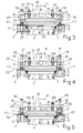
- the drawer 3 reaches the tray packaging station, the said drawer is centred vertically in a precision manner relative to the overlying operating head 15 which is located at a suitable distance from the film 112 and which is connected to vertical raising and lowering means 16, the thrust of which during the downward stroke may be programmed (see below).
- the head 15 has an upper table 115 which is directly connected to the vertical movement means 16 and which has, mounted on its perimeter underneath, linear pressers 17 with a bottom lining 117 of suitable elastically yielding material, formed integrally with vertical rods 18 which pass in a guided manner through corresponding vertical holes 19 provided in the table 115 and are provided at the top with an anti-extraction head 118 and for example are fitted along the section underneath the said table 115 with cylindrical-helix springs 20 which have suitable properties.
- the pressers 17 have their bottom side which lies in a common horizontal ideal plane and are arranged so that, when the head 15 is lowered during the active working stroke, the said pressers touch with their bottom rubber-lined side a portion of the film 112 which is situated outside and all the way around the annular channel 4 of the drawer 3, as shown in Figure 3, so as to fix the said film on the said drawer 3.
- the pipe 8 may be connected permanently to the source supplying the modified atmosphere, for example by means of a flexible tube, or the connection to this station may be performed in an impromptu manner, only when the drawer 3 is situated underneath the operating head 15, by means of a coupling mounted on special raising and lowering means, all of which in a manner which can be readily and easily realized by persons skilled in the art.
- the modified atmosphere gradually occupies the said chamber C, expelling the air through the duct 11, until this chamber is completely saturated.
- the modified atmosphere may be supplied continuously, with a constant pressure or with a variable pressure, or may be supplied at a constant pressure, but intermittently, depending on the requirements which may be conditioned by the shape and/or the quantity of product placed inside the tray V.
- the modified atmosphere which will be trapped inside the tray V must not be under pressure, so that, also so as to favour initial evacuation of the air from the said tray, the sum of the cross-sections of the discharge mouths 10 is equal to or greater than the sum of the cross-sections of the supply mouths 7, 107 (Fig. 1).
- the discharge duct 11 may, for example, be connected to a variable throttling device which is driven by means which will allow it to intervene during the final stage of the cycle for internal conditioning of the tray, so as to slow down discharging and achieve the desired pressure condition inside the said tray.
- the same upper table 115 of the head unit 15 has, suspended from it, a welding plate 21 which is provided at the bottom with a horizontal edge 121 projecting downwards and lined with a suitable material which is non-adhesive with respect to the film and heated by suitable electric resistances 22 which are housed in the said plate 21 and connected to the power supply bush 122 and operation of which is controlled by at least one temperature probe 23.
- the bottom edge 121 of the heating plate 21 is such as to reproduce the plan-view form of the upper edge B of the tray V and is initially raised from the ideal plane in which the bottom edge of the pressers 17 lies so that, during the aforementioned step for conditioning the internal atmosphere of the tray, the said edge 121 is suitably raised from the film 112.
- the welding plate 21 is suspended from the table 115 by means of vertical rods 24 which slide inside vertical guide seats 25 which are thermally insulated and situated in the same table 115 and on which the said rods 24 normally rest with their heads 124 both by means of gravity and as a result of the action of cylindrical-helix springs 26 which, for example, are fitted on the section of the rods 24 projecting underneath the guide seats 25.
- a shearing or cutting frame 27 is provided around the welding plate 21 and is fixed at the top at 127 to the perimetral edge of a recess of the table 115 and has a bottom edge 227 with a cutting action, for example having sawteeth and converging towards the plate 21.
- the edge 227 of the cutting frame 27 is suitably raised relative to the bottom edge 121 of the said plate 21, all of which so that when, during the lowering movement of the operating head 15, after operation of the foil-pressing pressers 17 and once conditioning of the internal atmosphere of the tray V has been performed, the bottom edge 121 of the welding plate touches the film 112 which is retained externally by the said pressers 17, stretches it suitably and pushes it onto the edge B of the tray, so as to heat-weld it onto this edge (see Figure 4), trapping the modified atmosphere for conserving the product inside the said tray.
- the head 15 is raised, as can be seen from Figure 2, and the drawer 3 with the packaged tray is moved away so as to allow the unloading of the said closed tray and its replacement with a new tray to be packaged.
- the means 112 for moving the film 112 are activated so that the waste material 112' of the film, produced during the previous cycle, is conveyed away towards the storage spool 14 and a new length of intact film is positioned underneath the closing and shearing head 15.
- the apparatus may be easily designed so as to handle simultaneously several trays, in particular if of medium-to-small format, arranged in succession with each other and/or alongside each other.
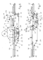
- the apparatus as described, may be mounted effectively in a part of the machine which performs the automatic movement of the drawer 3 and the trays V during loading and unloading into and from the drawer, as described in the patent application cited in the introduction and as illustrated schematically in Figures 6 and 7.
- roller 213 for driving the film which is situated downstream of the operating head 15, is mounted on an arm 29 mounted with the possibility of pivoting about a fulcrum 129 supported by the table 115 of the head 15 and that it is pushed downwards by spring means, not shown, all of which in such a way that, when the said head 15 is raised at the end of each working cycle, the length of film 112' in which a window was formed during the previous cycle, is arranged obliquely so as to allow unloading of the packaged tray underneath the raised roller 213.
- the trays V are fed forwards by means of a belt or band conveyor 30 driven over rollers 31, 131, 231, 331, 431 which are supported rotatably by the fixed chassis of the machine and the downstream roller 31 of which is connected to a drive unit 32 which is controlled by the processor for controlling the machine itself.
- the upper section of the conveyor 30 has an intermediate depression which has a length suitably greater than that of the trays to be treated during each cycle and in which the belts of this section of the conveyor follow a U-shaped path as a result of being driven over at least four rollers 33, 133, 233, 333 which are rotatably supported by a carriage 34 which may be displaced horizontally by suitable means from the position shown in Figure 6, where it is upstream of the head 15, for the tray loading and unloading operations (see below), into the position according to Figure 7 where it is situated underneath the head 15 for the operation of packaging the said trays.
- the front section 130 of the conveyor 30 travels over a flat structure 35 which is fixed to the chassis of the machine and has a length such as to support at least one tray V to be packaged, while the end part 230 of the upper section of the said conveyor is free of obstacles so as not hinder the travel of the carriage 34 on which the drawer 3 described above is mounted, in such a way that the upper side of the plate 6 of this drawer is coplanar with the upper section of the conveyor 30 in question.
- the same carriage 34 has, mounted thereon, the vertical guides 136 and the actuator for the vertical movement of a horizontal lifting table 36 which may be raised inside the opening 103 of the drawer 3, so as to be arranged with its upper side coplanar with that of the said drawer, as illustrated in broken lines in Figure 6, or which may be lowered as illustrated in continuous lines.
- the machine is completed by a fixed stop cross-bar 37 which is situated above the upstream roller 113 for driving the film, a further fixed stop cross-bar 38 situated upstream of the cross-bar 37 and a further cross-bar 39 situated upstream of the cross-bar 38, at a distance from the latter which is slightly greater than the length of the product to be fed into the drawer 3 and connected to raising and lowering means which are schematically indicated by the arrow 139.
- the carriage 34 is in the retracted position shown in Figure 6, with the lifting table 36 in the high position, with a tray V1 resting against the middle cross-bar 38 (see below) and detected by a sensor 40, with the cross-bar 39 lowered and with the conveyor 30 activated so that the next tray V2 is stopped against the said cross-bar 39 and detected by a sensor 41.
- the conveyor 30 stops, the lifting table 36 moves downwards so as to position the tray V1 on the rim 1, 2 of the drawer 3 and, when this condition is detected by the sensor 40, the forward movement of the carriage 34 is effected so as to bring the tray V1 underneath the head 15 in order to perform the operating steps described with reference to Figures 1 to 5.
- the conveyor 30 can be activated with simultaneous raising of the upstream cross-bar 39 so as to bring the tray V2 against the fixed middle cross-bar 38 and, when this condition is detected by the sensor 40, the said upstream cross-bar 39 is lowered and the conveyor 30 is stopped immediately or when the sensor 41 detects a further tray against the said lowered cross-bar 39.
- the lifting table 36 is raised and brings the closed tray V1 above the drawer 3 such that, when the carriage 34 is subsequently retracted towards the left, as can be seen from Figure 6, the same tray is retained by the fixed cross-bar 37 and is arranged on the upper right-hand section 230 of the conveyor 30 which is gradually lengthened and, when the carriage reaches the start-of-cycle position, it finds the tray V2 which is arranged on its lifting table 36 in the high position, ready to be inserted inside the drawer 3 for repetition of a new working cycle.
- the conveyor 30 is reactivated so as to move the closed tray V1 away from the head 15 and transfer it onto a motor-driven downstream conveyor 42, while the transfer of the packaging is detected by a sensor 43 which signals to the processor of the machine the correct execution of the working steps.
- the means for unwinding the film 112 from the reel 12 and the means for storing the waste material 112' on the spool 14 are activated so as to position a new intact and extended length of the said film 112 underneath the head 15.
Applications Claiming Priority (1)
| Application Number | Priority Date | Filing Date | Title |
|---|---|---|---|
| IT000249A ITBO20060249A1 (it) | 2006-04-05 | 2006-04-05 | Apparato e macchina per confezionare vaschette di prodotti in atmosfera modificata. |
Publications (3)
| Publication Number | Publication Date |
|---|---|
| EP1842776A2 true EP1842776A2 (de) | 2007-10-10 |
| EP1842776A3 EP1842776A3 (de) | 2007-10-31 |
| EP1842776B1 EP1842776B1 (de) | 2009-08-19 |
Family
ID=38123969
Family Applications (1)
| Application Number | Title | Priority Date | Filing Date |
|---|---|---|---|
| EP07104527A Active EP1842776B1 (de) | 2006-04-05 | 2007-03-20 | Vorrichtung zur Verpackung von Ablagen mit Produkten in einer modifizierten Atmosphäre |
Country Status (5)
| Country | Link |
|---|---|
| EP (1) | EP1842776B1 (de) |
| AT (1) | ATE440031T1 (de) |
| DE (1) | DE602007001993D1 (de) |
| ES (1) | ES2331210T3 (de) |
| IT (1) | ITBO20060249A1 (de) |
Cited By (21)
| Publication number | Priority date | Publication date | Assignee | Title |
|---|---|---|---|---|
| WO2009144714A2 (en) * | 2008-05-27 | 2009-12-03 | Hefestus Ltd | Food container sealing |
| ITMI20092003A1 (it) * | 2009-11-13 | 2011-05-14 | I L P R A S P A | Unità di sigillatura in atmosfera controllata di vaschette e/o simili contenitori per il confezionamento di prodotti alimentari |
| ITBO20100045A1 (it) * | 2010-01-26 | 2011-07-27 | Gruppo Fabbri S P A | Apparato per il confezionamento in atmosfera modificata di prodotti posti in vassoi. |
| ITMI20100471A1 (it) * | 2010-03-23 | 2011-09-24 | Tecnovac S R L | Macchina per eseguire il confezionamento, mediante sigillatura con film sintetico, di prodotti, in particolare prodotti alimentari, in contenitori del tipo vaschette, vassoi o simili, ad elevata flessibilità di impiego. |
| ITBO20100211A1 (it) * | 2010-04-08 | 2011-10-09 | Gruppo Fabbri S P A | Apparato a campane contrapposte, per il confezionamento in atmosfera modificata di prodotti posti in vassoi. |
| EP2468633A1 (de) * | 2010-12-27 | 2012-06-27 | Multivac Sepp Haggenmüller GmbH & Co. KG | Schalenverschließmaschine und Verfahren zum Betrieb einer solchen Schalenverschließmaschine |
| DE102012005891A1 (de) * | 2012-03-23 | 2013-09-26 | Multivac Sepp Haggenmüller Gmbh & Co. Kg | Verpackungsmaschine mit Siegelstation zum Begasen einer Verpackung |
| EP2676888A1 (de) * | 2012-06-22 | 2013-12-25 | Multivac Sepp Haggenmüller GmbH & Co. KG | Siegelvorrichtung einer Schalenverschließmaschine |
| WO2014080053A1 (es) * | 2012-11-21 | 2014-05-30 | Manuel Ruiz Carmona | Equipo para unir un cuerpo laminar a la embocadura de una caja |
| CN104003018A (zh) * | 2013-09-12 | 2014-08-27 | 温州市沪华机械电器有限公司 | 抽真空封口装置 |
| EP3095717A1 (de) | 2015-05-21 | 2016-11-23 | MULTIVAC Sepp Haggenmüller SE & Co. KG | Schalenverschliessmaschine |
| WO2016193006A1 (en) * | 2015-05-29 | 2016-12-08 | Cryovac, Inc. | Apparatus and process for packaging a product |
| WO2020002934A1 (en) * | 2018-06-29 | 2020-01-02 | Randox Laboratories Ltd | Cartridge sealing apparatus |
| WO2020044031A1 (en) * | 2018-08-29 | 2020-03-05 | Proseal Uk Limited | Packaging apparatus with a flushing gas inlet and outlet |
| US10741432B2 (en) * | 2017-02-06 | 2020-08-11 | Applied Materials, Inc. | Systems, apparatus, and methods for a load port door opener |
| EP3733528A1 (de) * | 2019-05-02 | 2020-11-04 | MULTIVAC Sepp Haggenmüller SE & Co. KG | Siegelwerkzeug und verfahren zum versiegeln von schalen |
| JP2021031179A (ja) * | 2019-08-27 | 2021-03-01 | 朱暁鳳 | 頼れる食品真空包装機 |
| US20220063849A1 (en) * | 2020-08-27 | 2022-03-03 | Sonoco Development, Inc. | Systems and methods for the application and sealing of end closures on containers |
| CN114408286A (zh) * | 2022-01-07 | 2022-04-29 | 江苏旭鹏智能科技有限公司 | 一种操作简单的连续盒式气调包装机 |
| WO2022099197A1 (en) * | 2020-11-09 | 2022-05-12 | Sonoco Development, Inc. | Seal and cut assembly for heat sealing machine |
| US11981471B2 (en) | 2021-11-09 | 2024-05-14 | Sonoco Development, Inc. | Seal and cut assembly for heat sealing machine |
Citations (5)
| Publication number | Priority date | Publication date | Assignee | Title |
|---|---|---|---|---|
| WO1997045324A1 (en) * | 1996-05-31 | 1997-12-04 | Ross Industries, Inc. | Food product wrapping |
| WO2000038992A1 (en) * | 1998-12-23 | 2000-07-06 | Cryovac, Inc. | Process for packaging high profile products in a modified atmosphere with an upwardly formed heat shrinkable film |
| WO2000050305A1 (en) * | 1999-02-24 | 2000-08-31 | Hefestus Ltd. | Packaging method and apparatus |
| US6202388B1 (en) * | 1998-11-06 | 2001-03-20 | Jescorp, Inc. | Controlled environment sealing apparatus and method |
| US20030196412A1 (en) * | 2002-04-19 | 2003-10-23 | Foulke Guy L. | Top formed packaging |
-
2006
- 2006-04-05 IT IT000249A patent/ITBO20060249A1/it unknown
-
2007
- 2007-03-20 EP EP07104527A patent/EP1842776B1/de active Active
- 2007-03-20 ES ES07104527T patent/ES2331210T3/es active Active
- 2007-03-20 AT AT07104527T patent/ATE440031T1/de not_active IP Right Cessation
- 2007-03-20 DE DE602007001993T patent/DE602007001993D1/de active Active
Patent Citations (5)
| Publication number | Priority date | Publication date | Assignee | Title |
|---|---|---|---|---|
| WO1997045324A1 (en) * | 1996-05-31 | 1997-12-04 | Ross Industries, Inc. | Food product wrapping |
| US6202388B1 (en) * | 1998-11-06 | 2001-03-20 | Jescorp, Inc. | Controlled environment sealing apparatus and method |
| WO2000038992A1 (en) * | 1998-12-23 | 2000-07-06 | Cryovac, Inc. | Process for packaging high profile products in a modified atmosphere with an upwardly formed heat shrinkable film |
| WO2000050305A1 (en) * | 1999-02-24 | 2000-08-31 | Hefestus Ltd. | Packaging method and apparatus |
| US20030196412A1 (en) * | 2002-04-19 | 2003-10-23 | Foulke Guy L. | Top formed packaging |
Cited By (39)
| Publication number | Priority date | Publication date | Assignee | Title |
|---|---|---|---|---|
| WO2009144714A3 (en) * | 2008-05-27 | 2010-01-28 | Hefestus Ltd | Food container sealing |
| WO2009144714A2 (en) * | 2008-05-27 | 2009-12-03 | Hefestus Ltd | Food container sealing |
| ITMI20092003A1 (it) * | 2009-11-13 | 2011-05-14 | I L P R A S P A | Unità di sigillatura in atmosfera controllata di vaschette e/o simili contenitori per il confezionamento di prodotti alimentari |
| US9150316B2 (en) | 2010-01-26 | 2015-10-06 | Gruppo Fabbri Vignola S.P.A. | Apparatus for modified atmosphere packaging of products placed in trays |
| ITBO20100045A1 (it) * | 2010-01-26 | 2011-07-27 | Gruppo Fabbri S P A | Apparato per il confezionamento in atmosfera modificata di prodotti posti in vassoi. |
| WO2011092103A1 (en) * | 2010-01-26 | 2011-08-04 | Gruppo Fabbri S.P.A. | Apparatus for modified atmosphere packaging of products placed in trays |
| ITMI20100471A1 (it) * | 2010-03-23 | 2011-09-24 | Tecnovac S R L | Macchina per eseguire il confezionamento, mediante sigillatura con film sintetico, di prodotti, in particolare prodotti alimentari, in contenitori del tipo vaschette, vassoi o simili, ad elevata flessibilità di impiego. |
| EP2380810A3 (de) * | 2010-03-23 | 2012-02-22 | Tecnovac S.r.L. | Maschine zum Verpacken durch Versiegeln mit synthetischem Film, Produkte, insbesondere Lebensmittelprodukte in Behältern wie Ablagen, Schläuchen oder dergleichen mit hoher Verwendungsvielfalt |
| AU2011237995B2 (en) * | 2010-04-08 | 2015-05-07 | Gruppo Fabbri Vignola S.P.A. | Apparatus with opposing housings for modified atmosphere packaging of products placed in trays |
| US9555910B2 (en) | 2010-04-08 | 2017-01-31 | Gruppo Fabbri Vignola S.P.A. | Apparatus with opposing housings for modified atmosphere packaging of products placed in trays |
| EP2555981B1 (de) | 2010-04-08 | 2018-06-27 | Gruppo Fabbri Vignola S.p.A. | Verfahren zum verpacken von in verpackungsschalen eingelegten produkten unter modifizierter atmosphäre |
| WO2011124548A1 (en) * | 2010-04-08 | 2011-10-13 | Gruppo Fabbri Vignola S.P.A. | Apparatus with opposing housings for modified atmosphere packaging of products placed in trays |
| ITBO20100211A1 (it) * | 2010-04-08 | 2011-10-09 | Gruppo Fabbri S P A | Apparato a campane contrapposte, per il confezionamento in atmosfera modificata di prodotti posti in vassoi. |
| EP2468633A1 (de) * | 2010-12-27 | 2012-06-27 | Multivac Sepp Haggenmüller GmbH & Co. KG | Schalenverschließmaschine und Verfahren zum Betrieb einer solchen Schalenverschließmaschine |
| US9481480B2 (en) | 2012-03-23 | 2016-11-01 | Multivac Sepp Haggenmueller Se & Co. Kg | Packaging machine with sealing station for gas flushing a package |
| DE102012005891A1 (de) * | 2012-03-23 | 2013-09-26 | Multivac Sepp Haggenmüller Gmbh & Co. Kg | Verpackungsmaschine mit Siegelstation zum Begasen einer Verpackung |
| EP2676888A1 (de) * | 2012-06-22 | 2013-12-25 | Multivac Sepp Haggenmüller GmbH & Co. KG | Siegelvorrichtung einer Schalenverschließmaschine |
| WO2014080053A1 (es) * | 2012-11-21 | 2014-05-30 | Manuel Ruiz Carmona | Equipo para unir un cuerpo laminar a la embocadura de una caja |
| CN104003018A (zh) * | 2013-09-12 | 2014-08-27 | 温州市沪华机械电器有限公司 | 抽真空封口装置 |
| EP3095717A1 (de) | 2015-05-21 | 2016-11-23 | MULTIVAC Sepp Haggenmüller SE & Co. KG | Schalenverschliessmaschine |
| WO2016193006A1 (en) * | 2015-05-29 | 2016-12-08 | Cryovac, Inc. | Apparatus and process for packaging a product |
| AU2016270276B2 (en) * | 2015-05-29 | 2019-10-10 | Cryovac, LLC. | Apparatus and process for packaging a product |
| CN107660192A (zh) * | 2015-05-29 | 2018-02-02 | 克里奥瓦克公司 | 用于包装产品的设备和工艺 |
| US10741432B2 (en) * | 2017-02-06 | 2020-08-11 | Applied Materials, Inc. | Systems, apparatus, and methods for a load port door opener |
| WO2020002934A1 (en) * | 2018-06-29 | 2020-01-02 | Randox Laboratories Ltd | Cartridge sealing apparatus |
| CN112638779A (zh) * | 2018-08-29 | 2021-04-09 | 普洛希尔英国有限公司 | 具有冲洗气体入口和出口的包装设备 |
| US11530062B2 (en) | 2018-08-29 | 2022-12-20 | Proseal Uk Limited | Gas flush injector |
| CN112638779B (zh) * | 2018-08-29 | 2023-02-03 | 普洛希尔英国有限公司 | 具有冲洗气体入口和出口的包装设备 |
| WO2020044031A1 (en) * | 2018-08-29 | 2020-03-05 | Proseal Uk Limited | Packaging apparatus with a flushing gas inlet and outlet |
| EP3733528B1 (de) * | 2019-05-02 | 2022-02-09 | MULTIVAC Sepp Haggenmüller SE & Co. KG | Siegelwerkzeug und verfahren zum versiegeln von schalen |
| US11492160B2 (en) | 2019-05-02 | 2022-11-08 | Multivac Sepp Haggenmueller Se & Co. Kg | Sealing tool and method for sealing trays |
| EP3733528A1 (de) * | 2019-05-02 | 2020-11-04 | MULTIVAC Sepp Haggenmüller SE & Co. KG | Siegelwerkzeug und verfahren zum versiegeln von schalen |
| DE102019206280A1 (de) * | 2019-05-02 | 2020-11-05 | Multivac Sepp Haggenmüller Se & Co. Kg | Siegelwerkzeug und Verfahren zum Versiegeln von Schalen |
| JP2021031179A (ja) * | 2019-08-27 | 2021-03-01 | 朱暁鳳 | 頼れる食品真空包装機 |
| US20220063849A1 (en) * | 2020-08-27 | 2022-03-03 | Sonoco Development, Inc. | Systems and methods for the application and sealing of end closures on containers |
| WO2022099197A1 (en) * | 2020-11-09 | 2022-05-12 | Sonoco Development, Inc. | Seal and cut assembly for heat sealing machine |
| EP4221963A4 (de) * | 2020-11-09 | 2024-05-01 | Sonoco Dev Inc | Dichtungs- und schneidanordnung für eine heisssiegelmaschine |
| US11981471B2 (en) | 2021-11-09 | 2024-05-14 | Sonoco Development, Inc. | Seal and cut assembly for heat sealing machine |
| CN114408286A (zh) * | 2022-01-07 | 2022-04-29 | 江苏旭鹏智能科技有限公司 | 一种操作简单的连续盒式气调包装机 |
Also Published As
| Publication number | Publication date |
|---|---|
| ITBO20060249A1 (it) | 2007-10-06 |
| DE602007001993D1 (de) | 2009-10-01 |
| ATE440031T1 (de) | 2009-09-15 |
| ES2331210T3 (es) | 2009-12-23 |
| EP1842776B1 (de) | 2009-08-19 |
| EP1842776A3 (de) | 2007-10-31 |
Similar Documents
| Publication | Publication Date | Title |
|---|---|---|
| EP1842776B1 (de) | Vorrichtung zur Verpackung von Ablagen mit Produkten in einer modifizierten Atmosphäre | |
| KR950011387B1 (ko) | 용기로부터 가스를 빼는 방법 및 장치 | |
| US7506491B2 (en) | Method and machine for packaging food products in trays sealingly closed at the top with a thermoplastic film | |
| EP2033764B1 (de) | Maschine zum formen, füllen und schliessen von behältern aus expandiertem polymer | |
| US20100287893A1 (en) | Packaging machine and method for closing containers with lids | |
| US7296390B2 (en) | Vacuum packaging machine having a plurality of vacuum chambers for performing a vacuum sealing operation on product packages | |
| US7464521B2 (en) | Vacuum packaging machine for product packages with multiple products | |
| JP2009173342A (ja) | 人間工学的な成形プラグの交換を行なうことができるウエブ包装システム | |
| JP2018002308A (ja) | ヒートシール可能な材料で作製されたバッグにある量の流動製品を充填するための自動包装機 | |
| KR101827788B1 (ko) | 수액백 포장봉지 진공포장 시스템 | |
| EP2722280A1 (de) | Verpackungsverfahren und Verpackungsvorrichtung | |
| US10926899B2 (en) | Machine for sealing containers and method for sealing a plurality of containers | |
| CA1165221A (en) | Apparatus and method for film packaging | |
| US4622800A (en) | Sterilizing method and apparatus | |
| KR20150014694A (ko) | 자동연속식 진공포장장치 | |
| KR101911666B1 (ko) | 페트병 포장장치 | |
| CN205293195U (zh) | 一种热成型真空包装机 | |
| US3700387A (en) | Vacuum bagging machine | |
| JP5605085B2 (ja) | ヒートシール包装装置 | |
| JP2011073715A (ja) | 不活性ガス置換充填包装機 | |
| CN112368214B (zh) | 用于供应物品的设备和方法 | |
| US20220348369A1 (en) | Sealing machine for the sealing of packages | |
| AU686758B2 (en) | Process and device for producing a flowable product package via a shell | |
| KR200386432Y1 (ko) | 소품 자동포장기 | |
| EP0468776A1 (de) | Verbesserungen von oder in Bezug auf Vorrichtungen zum Verpacken von Gegenständen |
Legal Events
| Date | Code | Title | Description |
|---|---|---|---|
| PUAI | Public reference made under article 153(3) epc to a published international application that has entered the european phase |
Free format text: ORIGINAL CODE: 0009012 |
|
| PUAL | Search report despatched |
Free format text: ORIGINAL CODE: 0009013 |
|
| AK | Designated contracting states |
Kind code of ref document: A2 Designated state(s): AT BE BG CH CY CZ DE DK EE ES FI FR GB GR HU IE IS IT LI LT LU LV MC MT NL PL PT RO SE SI SK TR |
|
| AX | Request for extension of the european patent |
Extension state: AL BA HR MK YU |
|
| AK | Designated contracting states |
Kind code of ref document: A3 Designated state(s): AT BE BG CH CY CZ DE DK EE ES FI FR GB GR HU IE IS IT LI LT LU LV MC MT NL PL PT RO SE SI SK TR |
|
| AX | Request for extension of the european patent |
Extension state: AL BA HR MK YU |
|
| 17P | Request for examination filed |
Effective date: 20080325 |
|
| 17Q | First examination report despatched |
Effective date: 20080425 |
|
| AKX | Designation fees paid |
Designated state(s): AT BE BG CH CY CZ DE DK EE ES FI FR GB GR HU IE IS IT LI LT LU LV MC MT NL PL PT RO SE SI SK TR |
|
| GRAP | Despatch of communication of intention to grant a patent |
Free format text: ORIGINAL CODE: EPIDOSNIGR1 |
|
| RAP1 | Party data changed (applicant data changed or rights of an application transferred) |
Owner name: GRUPPO FABBRI S.P.A. |
|
| GRAS | Grant fee paid |
Free format text: ORIGINAL CODE: EPIDOSNIGR3 |
|
| GRAA | (expected) grant |
Free format text: ORIGINAL CODE: 0009210 |
|
| AK | Designated contracting states |
Kind code of ref document: B1 Designated state(s): AT BE BG CH CY CZ DE DK EE ES FI FR GB GR HU IE IS IT LI LT LU LV MC MT NL PL PT RO SE SI SK TR |
|
| REG | Reference to a national code |
Ref country code: GB Ref legal event code: FG4D |
|
| REG | Reference to a national code |
Ref country code: CH Ref legal event code: EP |
|
| REG | Reference to a national code |
Ref country code: IE Ref legal event code: FG4D |
|
| REF | Corresponds to: |
Ref document number: 602007001993 Country of ref document: DE Date of ref document: 20091001 Kind code of ref document: P |
|
| REG | Reference to a national code |
Ref country code: ES Ref legal event code: FG2A Ref document number: 2331210 Country of ref document: ES Kind code of ref document: T3 |
|
| LTIE | Lt: invalidation of european patent or patent extension |
Effective date: 20090819 |
|
| PG25 | Lapsed in a contracting state [announced via postgrant information from national office to epo] |
Ref country code: SE Free format text: LAPSE BECAUSE OF FAILURE TO SUBMIT A TRANSLATION OF THE DESCRIPTION OR TO PAY THE FEE WITHIN THE PRESCRIBED TIME-LIMIT Effective date: 20090819 Ref country code: LT Free format text: LAPSE BECAUSE OF FAILURE TO SUBMIT A TRANSLATION OF THE DESCRIPTION OR TO PAY THE FEE WITHIN THE PRESCRIBED TIME-LIMIT Effective date: 20090819 Ref country code: AT Free format text: LAPSE BECAUSE OF FAILURE TO SUBMIT A TRANSLATION OF THE DESCRIPTION OR TO PAY THE FEE WITHIN THE PRESCRIBED TIME-LIMIT Effective date: 20090819 Ref country code: FI Free format text: LAPSE BECAUSE OF FAILURE TO SUBMIT A TRANSLATION OF THE DESCRIPTION OR TO PAY THE FEE WITHIN THE PRESCRIBED TIME-LIMIT Effective date: 20090819 Ref country code: IS Free format text: LAPSE BECAUSE OF FAILURE TO SUBMIT A TRANSLATION OF THE DESCRIPTION OR TO PAY THE FEE WITHIN THE PRESCRIBED TIME-LIMIT Effective date: 20091219 |
|
| NLV1 | Nl: lapsed or annulled due to failure to fulfill the requirements of art. 29p and 29m of the patents act | ||
| PG25 | Lapsed in a contracting state [announced via postgrant information from national office to epo] |
Ref country code: PL Free format text: LAPSE BECAUSE OF FAILURE TO SUBMIT A TRANSLATION OF THE DESCRIPTION OR TO PAY THE FEE WITHIN THE PRESCRIBED TIME-LIMIT Effective date: 20090819 Ref country code: NL Free format text: LAPSE BECAUSE OF FAILURE TO SUBMIT A TRANSLATION OF THE DESCRIPTION OR TO PAY THE FEE WITHIN THE PRESCRIBED TIME-LIMIT Effective date: 20090819 Ref country code: LV Free format text: LAPSE BECAUSE OF FAILURE TO SUBMIT A TRANSLATION OF THE DESCRIPTION OR TO PAY THE FEE WITHIN THE PRESCRIBED TIME-LIMIT Effective date: 20090819 Ref country code: SI Free format text: LAPSE BECAUSE OF FAILURE TO SUBMIT A TRANSLATION OF THE DESCRIPTION OR TO PAY THE FEE WITHIN THE PRESCRIBED TIME-LIMIT Effective date: 20090819 |
|
| PG25 | Lapsed in a contracting state [announced via postgrant information from national office to epo] |
Ref country code: BG Free format text: LAPSE BECAUSE OF FAILURE TO SUBMIT A TRANSLATION OF THE DESCRIPTION OR TO PAY THE FEE WITHIN THE PRESCRIBED TIME-LIMIT Effective date: 20091119 Ref country code: PT Free format text: LAPSE BECAUSE OF FAILURE TO SUBMIT A TRANSLATION OF THE DESCRIPTION OR TO PAY THE FEE WITHIN THE PRESCRIBED TIME-LIMIT Effective date: 20091221 Ref country code: CY Free format text: LAPSE BECAUSE OF FAILURE TO SUBMIT A TRANSLATION OF THE DESCRIPTION OR TO PAY THE FEE WITHIN THE PRESCRIBED TIME-LIMIT Effective date: 20090819 |
|
| PG25 | Lapsed in a contracting state [announced via postgrant information from national office to epo] |
Ref country code: DK Free format text: LAPSE BECAUSE OF FAILURE TO SUBMIT A TRANSLATION OF THE DESCRIPTION OR TO PAY THE FEE WITHIN THE PRESCRIBED TIME-LIMIT Effective date: 20090819 Ref country code: RO Free format text: LAPSE BECAUSE OF FAILURE TO SUBMIT A TRANSLATION OF THE DESCRIPTION OR TO PAY THE FEE WITHIN THE PRESCRIBED TIME-LIMIT Effective date: 20090819 Ref country code: CZ Free format text: LAPSE BECAUSE OF FAILURE TO SUBMIT A TRANSLATION OF THE DESCRIPTION OR TO PAY THE FEE WITHIN THE PRESCRIBED TIME-LIMIT Effective date: 20090819 Ref country code: EE Free format text: LAPSE BECAUSE OF FAILURE TO SUBMIT A TRANSLATION OF THE DESCRIPTION OR TO PAY THE FEE WITHIN THE PRESCRIBED TIME-LIMIT Effective date: 20090819 |
|
| PG25 | Lapsed in a contracting state [announced via postgrant information from national office to epo] |
Ref country code: SK Free format text: LAPSE BECAUSE OF FAILURE TO SUBMIT A TRANSLATION OF THE DESCRIPTION OR TO PAY THE FEE WITHIN THE PRESCRIBED TIME-LIMIT Effective date: 20090819 |
|
| PLBE | No opposition filed within time limit |
Free format text: ORIGINAL CODE: 0009261 |
|
| STAA | Information on the status of an ep patent application or granted ep patent |
Free format text: STATUS: NO OPPOSITION FILED WITHIN TIME LIMIT |
|
| PG25 | Lapsed in a contracting state [announced via postgrant information from national office to epo] |
Ref country code: BE Free format text: LAPSE BECAUSE OF FAILURE TO SUBMIT A TRANSLATION OF THE DESCRIPTION OR TO PAY THE FEE WITHIN THE PRESCRIBED TIME-LIMIT Effective date: 20090819 |
|
| 26N | No opposition filed |
Effective date: 20100520 |
|
| PG25 | Lapsed in a contracting state [announced via postgrant information from national office to epo] |
Ref country code: MC Free format text: LAPSE BECAUSE OF NON-PAYMENT OF DUE FEES Effective date: 20100331 Ref country code: GR Free format text: LAPSE BECAUSE OF FAILURE TO SUBMIT A TRANSLATION OF THE DESCRIPTION OR TO PAY THE FEE WITHIN THE PRESCRIBED TIME-LIMIT Effective date: 20091120 |
|
| PG25 | Lapsed in a contracting state [announced via postgrant information from national office to epo] |
Ref country code: IE Free format text: LAPSE BECAUSE OF NON-PAYMENT OF DUE FEES Effective date: 20100320 |
|
| PG25 | Lapsed in a contracting state [announced via postgrant information from national office to epo] |
Ref country code: MT Free format text: LAPSE BECAUSE OF FAILURE TO SUBMIT A TRANSLATION OF THE DESCRIPTION OR TO PAY THE FEE WITHIN THE PRESCRIBED TIME-LIMIT Effective date: 20090819 |
|
| PGRI | Patent reinstated in contracting state [announced from national office to epo] |
Ref country code: IT Effective date: 20110501 |
|
| REG | Reference to a national code |
Ref country code: CH Ref legal event code: PL |
|
| PG25 | Lapsed in a contracting state [announced via postgrant information from national office to epo] |
Ref country code: CH Free format text: LAPSE BECAUSE OF NON-PAYMENT OF DUE FEES Effective date: 20110331 Ref country code: LI Free format text: LAPSE BECAUSE OF NON-PAYMENT OF DUE FEES Effective date: 20110331 |
|
| PG25 | Lapsed in a contracting state [announced via postgrant information from national office to epo] |
Ref country code: HU Free format text: LAPSE BECAUSE OF FAILURE TO SUBMIT A TRANSLATION OF THE DESCRIPTION OR TO PAY THE FEE WITHIN THE PRESCRIBED TIME-LIMIT Effective date: 20100220 Ref country code: LU Free format text: LAPSE BECAUSE OF NON-PAYMENT OF DUE FEES Effective date: 20100320 |
|
| PG25 | Lapsed in a contracting state [announced via postgrant information from national office to epo] |
Ref country code: TR Free format text: LAPSE BECAUSE OF FAILURE TO SUBMIT A TRANSLATION OF THE DESCRIPTION OR TO PAY THE FEE WITHIN THE PRESCRIBED TIME-LIMIT Effective date: 20090819 |
|
| REG | Reference to a national code |
Ref country code: DE Ref legal event code: R082 Ref document number: 602007001993 Country of ref document: DE Representative=s name: BUSCHHOFF-HENNICKE-ALTHAUS, DE |
|
| REG | Reference to a national code |
Ref country code: DE Ref legal event code: R081 Ref document number: 602007001993 Country of ref document: DE Owner name: GRUPPO FABBRI VIGNOLA S.P.A., IT Free format text: FORMER OWNER: GRUPPO FABBRI S.P.A., VIGNOLA, MODENA, IT Effective date: 20140526 Ref country code: DE Ref legal event code: R081 Ref document number: 602007001993 Country of ref document: DE Owner name: GRUPPO FABBRI VIGNOLA S.P.A., IT Free format text: FORMER OWNER: GRUPPO FABBRI S.P.A., VIGNOLA, IT Effective date: 20140526 Ref country code: DE Ref legal event code: R082 Ref document number: 602007001993 Country of ref document: DE Representative=s name: BUSCHHOFF-HENNICKE-ALTHAUS, DE Effective date: 20140526 |
|
| REG | Reference to a national code |
Ref country code: ES Ref legal event code: PC2A Owner name: GRUPO FABBRI VIGNOLA S.P.A Effective date: 20140708 |
|
| REG | Reference to a national code |
Ref country code: FR Ref legal event code: TP Owner name: GRUPPO FABBRI VIGNOLA S.P.A., IT Effective date: 20140725 |
|
| REG | Reference to a national code |
Ref country code: FR Ref legal event code: PLFP Year of fee payment: 10 |
|
| REG | Reference to a national code |
Ref country code: FR Ref legal event code: PLFP Year of fee payment: 11 |
|
| REG | Reference to a national code |
Ref country code: FR Ref legal event code: PLFP Year of fee payment: 12 |
|
| PGFP | Annual fee paid to national office [announced via postgrant information from national office to epo] |
Ref country code: FR Payment date: 20230322 Year of fee payment: 17 |
|
| PGFP | Annual fee paid to national office [announced via postgrant information from national office to epo] |
Ref country code: IT Payment date: 20230306 Year of fee payment: 17 |
|
| PGFP | Annual fee paid to national office [announced via postgrant information from national office to epo] |
Ref country code: ES Payment date: 20230527 Year of fee payment: 17 |
|
| PGFP | Annual fee paid to national office [announced via postgrant information from national office to epo] |
Ref country code: DE Payment date: 20240320 Year of fee payment: 18 Ref country code: GB Payment date: 20240320 Year of fee payment: 18 |