EP1842003B1 - Kryogenes transfersystem - Google Patents
Kryogenes transfersystem Download PDFInfo
- Publication number
- EP1842003B1 EP1842003B1 EP06701223A EP06701223A EP1842003B1 EP 1842003 B1 EP1842003 B1 EP 1842003B1 EP 06701223 A EP06701223 A EP 06701223A EP 06701223 A EP06701223 A EP 06701223A EP 1842003 B1 EP1842003 B1 EP 1842003B1
- Authority
- EP
- European Patent Office
- Prior art keywords
- vessel
- receiving room
- piping
- gas
- receiving
- Prior art date
- Legal status (The legal status is an assumption and is not a legal conclusion. Google has not performed a legal analysis and makes no representation as to the accuracy of the status listed.)
- Expired - Lifetime
Links
Images


Classifications
-
- F—MECHANICAL ENGINEERING; LIGHTING; HEATING; WEAPONS; BLASTING
- F17—STORING OR DISTRIBUTING GASES OR LIQUIDS
- F17C—VESSELS FOR CONTAINING OR STORING COMPRESSED, LIQUEFIED OR SOLIDIFIED GASES; FIXED-CAPACITY GAS-HOLDERS; FILLING VESSELS WITH, OR DISCHARGING FROM VESSELS, COMPRESSED, LIQUEFIED, OR SOLIDIFIED GASES
- F17C6/00—Methods and apparatus for filling vessels not under pressure with liquefied or solidified gases
-
- F—MECHANICAL ENGINEERING; LIGHTING; HEATING; WEAPONS; BLASTING
- F17—STORING OR DISTRIBUTING GASES OR LIQUIDS
- F17C—VESSELS FOR CONTAINING OR STORING COMPRESSED, LIQUEFIED OR SOLIDIFIED GASES; FIXED-CAPACITY GAS-HOLDERS; FILLING VESSELS WITH, OR DISCHARGING FROM VESSELS, COMPRESSED, LIQUEFIED, OR SOLIDIFIED GASES
- F17C2203/00—Vessel construction, in particular walls or details thereof
- F17C2203/03—Thermal insulations
- F17C2203/0375—Thermal insulations by gas
-
- F—MECHANICAL ENGINEERING; LIGHTING; HEATING; WEAPONS; BLASTING
- F17—STORING OR DISTRIBUTING GASES OR LIQUIDS
- F17C—VESSELS FOR CONTAINING OR STORING COMPRESSED, LIQUEFIED OR SOLIDIFIED GASES; FIXED-CAPACITY GAS-HOLDERS; FILLING VESSELS WITH, OR DISCHARGING FROM VESSELS, COMPRESSED, LIQUEFIED, OR SOLIDIFIED GASES
- F17C2203/00—Vessel construction, in particular walls or details thereof
- F17C2203/03—Thermal insulations
- F17C2203/0391—Thermal insulations by vacuum
-
- F—MECHANICAL ENGINEERING; LIGHTING; HEATING; WEAPONS; BLASTING
- F17—STORING OR DISTRIBUTING GASES OR LIQUIDS
- F17C—VESSELS FOR CONTAINING OR STORING COMPRESSED, LIQUEFIED OR SOLIDIFIED GASES; FIXED-CAPACITY GAS-HOLDERS; FILLING VESSELS WITH, OR DISCHARGING FROM VESSELS, COMPRESSED, LIQUEFIED, OR SOLIDIFIED GASES
- F17C2203/00—Vessel construction, in particular walls or details thereof
- F17C2203/06—Materials for walls or layers thereof; Properties or structures of walls or their materials
- F17C2203/0634—Materials for walls or layers thereof
- F17C2203/0636—Metals
- F17C2203/0639—Steels
- F17C2203/0643—Stainless steels
-
- F—MECHANICAL ENGINEERING; LIGHTING; HEATING; WEAPONS; BLASTING
- F17—STORING OR DISTRIBUTING GASES OR LIQUIDS
- F17C—VESSELS FOR CONTAINING OR STORING COMPRESSED, LIQUEFIED OR SOLIDIFIED GASES; FIXED-CAPACITY GAS-HOLDERS; FILLING VESSELS WITH, OR DISCHARGING FROM VESSELS, COMPRESSED, LIQUEFIED, OR SOLIDIFIED GASES
- F17C2203/00—Vessel construction, in particular walls or details thereof
- F17C2203/06—Materials for walls or layers thereof; Properties or structures of walls or their materials
- F17C2203/0634—Materials for walls or layers thereof
- F17C2203/0636—Metals
- F17C2203/0646—Aluminium
-
- F—MECHANICAL ENGINEERING; LIGHTING; HEATING; WEAPONS; BLASTING
- F17—STORING OR DISTRIBUTING GASES OR LIQUIDS
- F17C—VESSELS FOR CONTAINING OR STORING COMPRESSED, LIQUEFIED OR SOLIDIFIED GASES; FIXED-CAPACITY GAS-HOLDERS; FILLING VESSELS WITH, OR DISCHARGING FROM VESSELS, COMPRESSED, LIQUEFIED, OR SOLIDIFIED GASES
- F17C2203/00—Vessel construction, in particular walls or details thereof
- F17C2203/06—Materials for walls or layers thereof; Properties or structures of walls or their materials
- F17C2203/0634—Materials for walls or layers thereof
- F17C2203/0658—Synthetics
- F17C2203/066—Plastics
-
- F—MECHANICAL ENGINEERING; LIGHTING; HEATING; WEAPONS; BLASTING
- F17—STORING OR DISTRIBUTING GASES OR LIQUIDS
- F17C—VESSELS FOR CONTAINING OR STORING COMPRESSED, LIQUEFIED OR SOLIDIFIED GASES; FIXED-CAPACITY GAS-HOLDERS; FILLING VESSELS WITH, OR DISCHARGING FROM VESSELS, COMPRESSED, LIQUEFIED, OR SOLIDIFIED GASES
- F17C2205/00—Vessel construction, in particular mounting arrangements, attachments or identifications means
- F17C2205/01—Mounting arrangements
- F17C2205/0153—Details of mounting arrangements
- F17C2205/0184—Attachments to the ground, e.g. mooring or anchoring
-
- F—MECHANICAL ENGINEERING; LIGHTING; HEATING; WEAPONS; BLASTING
- F17—STORING OR DISTRIBUTING GASES OR LIQUIDS
- F17C—VESSELS FOR CONTAINING OR STORING COMPRESSED, LIQUEFIED OR SOLIDIFIED GASES; FIXED-CAPACITY GAS-HOLDERS; FILLING VESSELS WITH, OR DISCHARGING FROM VESSELS, COMPRESSED, LIQUEFIED, OR SOLIDIFIED GASES
- F17C2205/00—Vessel construction, in particular mounting arrangements, attachments or identifications means
- F17C2205/01—Mounting arrangements
- F17C2205/0153—Details of mounting arrangements
- F17C2205/0192—Details of mounting arrangements with external bearing means
-
- F—MECHANICAL ENGINEERING; LIGHTING; HEATING; WEAPONS; BLASTING
- F17—STORING OR DISTRIBUTING GASES OR LIQUIDS
- F17C—VESSELS FOR CONTAINING OR STORING COMPRESSED, LIQUEFIED OR SOLIDIFIED GASES; FIXED-CAPACITY GAS-HOLDERS; FILLING VESSELS WITH, OR DISCHARGING FROM VESSELS, COMPRESSED, LIQUEFIED, OR SOLIDIFIED GASES
- F17C2225/00—Handled fluid after transfer, i.e. state of fluid after transfer from the vessel
- F17C2225/01—Handled fluid after transfer, i.e. state of fluid after transfer from the vessel characterised by the phase
- F17C2225/0146—Two-phase
- F17C2225/0153—Liquefied gas, e.g. LPG, GPL
- F17C2225/0161—Liquefied gas, e.g. LPG, GPL cryogenic, e.g. LNG, GNL, PLNG
-
- F—MECHANICAL ENGINEERING; LIGHTING; HEATING; WEAPONS; BLASTING
- F17—STORING OR DISTRIBUTING GASES OR LIQUIDS
- F17C—VESSELS FOR CONTAINING OR STORING COMPRESSED, LIQUEFIED OR SOLIDIFIED GASES; FIXED-CAPACITY GAS-HOLDERS; FILLING VESSELS WITH, OR DISCHARGING FROM VESSELS, COMPRESSED, LIQUEFIED, OR SOLIDIFIED GASES
- F17C2227/00—Transfer of fluids, i.e. method or means for transferring the fluid; Heat exchange with the fluid
- F17C2227/01—Propulsion of the fluid
- F17C2227/0128—Propulsion of the fluid with pumps or compressors
- F17C2227/0135—Pumps
-
- F—MECHANICAL ENGINEERING; LIGHTING; HEATING; WEAPONS; BLASTING
- F17—STORING OR DISTRIBUTING GASES OR LIQUIDS
- F17C—VESSELS FOR CONTAINING OR STORING COMPRESSED, LIQUEFIED OR SOLIDIFIED GASES; FIXED-CAPACITY GAS-HOLDERS; FILLING VESSELS WITH, OR DISCHARGING FROM VESSELS, COMPRESSED, LIQUEFIED, OR SOLIDIFIED GASES
- F17C2260/00—Purposes of gas storage and gas handling
- F17C2260/03—Dealing with losses
- F17C2260/035—Dealing with losses of fluid
- F17C2260/037—Handling leaked fluid
-
- F—MECHANICAL ENGINEERING; LIGHTING; HEATING; WEAPONS; BLASTING
- F17—STORING OR DISTRIBUTING GASES OR LIQUIDS
- F17C—VESSELS FOR CONTAINING OR STORING COMPRESSED, LIQUEFIED OR SOLIDIFIED GASES; FIXED-CAPACITY GAS-HOLDERS; FILLING VESSELS WITH, OR DISCHARGING FROM VESSELS, COMPRESSED, LIQUEFIED, OR SOLIDIFIED GASES
- F17C2270/00—Applications
- F17C2270/05—Applications for industrial use
- F17C2270/0509—"Dewar" vessels
Definitions
- the present invention regards a system for transferral of at least a cryogenic fluid between two objects, for instance an installation and a vessel.
- a cryogenic fluid typically LPG or LNG
- LPG liquid propane gas
- LNG liquid propane gas
- a cryogenic fluid typically LPG or LNG
- all equipment in the vicinity of the spilled liquid will be cooled down to the boiling temperature of the liquid, which for LPG can be typically -50 degrees C and for LNG typically -164 degrees C.
- Most vessels and equipment are built of carbon steel that will turn brittle and loose its structural strength at cryogenic temperatures.
- LNG may be carried through closed spaces inside the ship. This could be for instance in the OCL (Offshore Cryogenic Loading) LNG transfer system, where LNG is received in a purpose built structure in the bow of the ship, in compartments used to transfer LNG to the propulsion or generator motor or in a swivel compartment for instance described in WO 99/38762 or WO 01/34460 .
- OCL Offshore Cryogenic Loading
- US 6793740 there is described a system for transfer of LPG and other chemicals. There may be further use of transfer of cryogenic fluids from one floating vessel to another floating vessel, by for instance a submerged buoy system, which gives other demands for the transfer system.
- the cryogenic liquid is maintained at or close to its boiling point at low temperature and any contact with other material at a higher temperature will result in transfer of heat from the material to the liquid and boil-off of liquid and cool down of the material.
- the liquid is therefore normally stored in well insulated pipes and tanks and all transfer is carried out with dedicated equipment and according to predetermined and approved procedures to reduce the risk of spill and accidents.
- cryogenic fluid Another issue in relation to the transfer of cryogenic fluid is that any human exposure to the liquid or cold gas may result in serious injury or death. Protection of personnel can be achieved by either prohibiting personnel to enter the area when cold media is present and can leak out, or by use of adequate protective equipment. At this time protective equipment is limited to space suits and similar clothing which by nature is either prohibitive expensive or not available at such sites. As a general rule unprotected personnel should therefore not be admitted to enclosed spaces where there is a possibility that LNG may escape (from for instance rotating equipment or flanged connections). Equipment inside such space must therefore be remotely operated and monitored and all containers with cryogenic liquid must be drained and inerted before personnel can enter.
- Cryogenic liquids are normally not corrosive or destructive to the environment other than by cooling down all exposed material to low temperature and replacing the atmosphere by the product liquid and gas.
- Cryogenic liquids are normally of a low specific gravity (typically less than 0,5 kg/l) and will float on top of most other liquids. Loose material will tend to sink in the liquid.
- the boil-off gas will at ambient temperature (+10 degrees C to say 50 degrees C) normally be lighter than air and will therefore tend to move upwards and mix with air. However, boil-off gas at very low temperature will be heavier than air at ambient temperature.
- a release of cryogenic fluid inside an enclosed compartment will therefore tend to form cold product gas at the bottom and expel the original atmosphere at the top. As the product gas heat up it will tend to rise upwards in the compartment. Removal of product gas should therefore be performed by blowing in air (or inert gas) at as high temperature as practical to evaporate liquid spill and to heat up and expel the cold gas.
- liquid cryogenic fluid As long as liquid cryogenic fluid is present it will exist at its boiling temperature at the actual ambient storage pressure. Any input of heat will result in boil-off and if no heat is added the temperature of all exposed material will fall until the boiling temperature of the liquid has been reached, where after the boil off will be reduced to equalize the heat influx.
- Equipment inside a compartment can be protected from the low temperature by insulation or by adding heat to the equipment, typically by heating coils or resistance heating elements wrapped around the sensitive parts. Insulation of free standing equipment inside the enclosed space will have a practical limitation in protection time if no heat is added, as it is not possible to insulate any equipment perfectly. With time the equipment inside the insulation will be cooled down to the boiling temperature of the liquid on the outside.
- Parts that are insulated on the outside and where heat is added on the inside can be maintained at any desired temperature for any period of time as long as the flow of heat supplied is higher than the heat removed on the exposed side of the insulation.
- Transfer of heat from one media to another is either done by radiation through vacuum or a gas or by heat flow through the material.
- Vacuum is the best insulation and reflective material is used together with vacuum, or almost vacuum, to reflect heat radiation. Most insulation principles are therefore based either on vacuum, reflective material or fixed foam, or gas which is a better heat insulator than solid material.
- An aim of the present invention is to provide a system for transferral of at least one cryogenic fluid, which is safer in respect of protection of personnel, in the case of any spillage of fluid and or in the protection against possible spillage of fluid.
- Another aim is to provide a specifically good solution for the case where one has transfer of cryogenic fluids between an installation and a floating vessel or between two vessels, where at least one of them has a single mooring point, and the transfer pipes runs through the single mooring point.
- the present invention as defined in the following claims provides a system that fulfils the above mentioned aims.
- the system regards transferral of at least one cryogenic fluid between two objects for instance an installation and a vessel.
- At least one transfer pipes is extending from the one object, the installation and into a receiving room in the other object, the vessel. These transfer pipes are connectable with piping on the vessel through connection means in the receiving room.
- the receiving room is closable for instance for human entry during transfer. Closable should in this application be interpreted to mean fully closed, as scaled off in relation the surroundings or closed off for human entry into the surroundings of the transfer elements, but with an aperture in the mainly vertically highest points for evacuation of eventual boil off to the atmosphere.
- the aperture is however positioned in a manner and in a distance from any position personnel may be in during transfer to keep them from harm in case of a leakage, for instance above an upper deck level.
- the connection means, at least a part of the receiving room and or other elements in the receiving room comprises means to withstand eventual leakage of the cryogenic fluid and the system also comprises means for evacuating the receiving room for eventual spilled fluid.
- the cryogenic fluid may be LNG or LPG or other cryogenic fluid, and the system may also comprise possibilities for transfer of other fluids or media.
- the objects may be a land based installation and a floating vessel, two vessels, an underwater installation and a vessel, a vessel and a floating platform, or similar constellations.
- the floating object as a vessel or a floating platform, may have a fixed mooring to the seabed as a tension leg platform or have a single point mooring system which may be releasable.
- At least a part of the walls, roof and or floor construction of the receiving room is formed with insulation voids in the construction and or covered with an insulating material and or formed with a more cold resistant material than the rest of the vessel.
- the possibility of forming the elements within and at least parts of the receiving room in for instance a material such as stainless steel (typically AISI 304/316, Duplex Stainless Steel), aluminium or "plastic” material such as Teflon or similar, which are not suitable for forming the rest of the vessel of, would give the needed cold resistance in case of spillage of cryogenic fluid within the receiving room.
- a material such as stainless steel (typically AISI 304/316, Duplex Stainless Steel), aluminium or "plastic” material such as Teflon or similar, which are not suitable for forming the rest of the vessel of, would give the needed cold resistance in case of spillage of cryogenic fluid within the receiving room.
- a material such as stainless steel (
- Having the receiving room closable gives the benefit of having a well defined area for limiting the eventual spilled cryogenic fluid. It also gives the possibility of adding a fluid for instance an inert gas, as nitrogen into the room during transfer, and or the possibility of easy cleaning of the room after an eventual spillage of fluid. Another issue is that the room may have locking means linked to the transfer operation which prevent personnel from entering the room during transfer.
- the transfer pipes and or piping on the vessel are at least doubly mantled, with vacuum and or a specific gas at a pressure equal to or larger than the pressure within the pipe or piping, in the voids between an inner and an outer mantel of the pipes.
- the gas may for instance be nitrogen or an inert gas.
- Heat may also be artificially added by circulating heated gas or by use of for instance electric heating elements.
- the pipe from the installation goes through a turret arrangement, which may form a single mooring point for the vessel.
- the turret may be arranged amidships or in the bow or stem of the vessel.
- the turret arrangement is arranged on bearings on/in the vessel, the connecting means being swivel means, where at least a part of the turret and or at least a part of the construction forming the receiving room are formed with voids with vacuum/gas or formed with other insulation means to withstand eventual spillage.
- the turret is releasable attached to the vessel, and may be a submerged buoy with a turret releasable arranged in receiving means, arranged at the vessel close the bottom of the hull.
- the receiving means being a part of the hull of the vessel which corresponds to the form of a part of the buoy, for instance a truncated cone or partly spherical.
- bearing means and or the locking means for the buoy/turret arrangement are arranged within the receiving room and formed to withstand eventual spillage. In another embodiment they may be arranged outside the receiving room, for instance on deck above or below the receiving room.
- the means for evacuating the receiving room may in one embodiment comprise an opening in the bottom of the receiving room leading to a drain tank comprising a pump and piping for moving the spilled fluid back into the system or to another system.
- At least a part of the area around the receiving means comprises insulation means in form of an insulation clad and or sections of the hull made to withstand spillage of cryogenic fluid, by forming vacuum or gas voids in the structure forming the hull and or forming the section of the hull by a more cold resistant material than the rest of the vessel.
- the hull of the vessel has in one embodiment a part around the receiving means formed with recesses or tunnels for evacuation of eventual trapped cryogenic liquid.
- the piping within the receiving room is in one embodiment an articulated piping, for connecting to and releasing of the connection to the pipe from the installation.
- the articulated piping is in one embodiment formed by introducing swivel means between more or less rigid piping sections.
- Flanges and or other connection means between two elements forming a fluid channel in the system are in one preferred embodiment formed with at least a double seal means arrangement with introduction of a fluid between the double seals, at a pressure equal to or higher than the pressure of the fluid transferred in the elements.
- the fluid is preferably a gas as nitrogen or another inert gas.
- the closable receiving room when transferring cryogenic fluid through the system is filled with a gas at a pressure equal to or higher than the pressure of the cryogenic fluid, and or cleaned with an inert gas after transferral of cryogenic fluid before personnel may enter the receiving room.
- the present invention regards a transfer system as schematically shown in fig. 1 .
- the system comprises transfer pipes from one object, for instance an installation 1 which may be land based, floating in the water or a sub sea installation, to another object 2 which may be a vessel for transport.
- the receiving room may for a transport vessel be in the bow stern or amidships or between.
- the transfer pipe 3 extends from a sub sea installation and or another floating object and is connected to turret means, which in the shown embodiment is a part of a normally submerged buoy 20.
- the buoy 20 is received in receiving means in the hull of the vessel, for mooring and transfer of fluid.
- the transfer pies 3 are through connection means 6, connected to the piping 5 onboard the vessel 2, in a manner so that the vessel may rotate around the mooring point and the transfer pipes 3 do not experience unnecessary stress. This is a well know mooring and transfer system at sea, where there are weather conditions which demand quick release and an ability to change the position of the vessel dependent on weather and sea conditions.
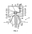
- the transfer pipe 3 is guided through a buoy 20 and connected to the piping 5 onboard the vessel 2 through connection means 6 in a closable receiving room 4.
- the buoy 20 is formed with a surface section 21, in this embodiment as a truncated cone, corresponding to receiving means 13 provided for in a section of the hull 7 of the vessel 2.
- the buoy 20 may also be provided with a void 22, for buoyancy and or insulation.
- the structure forming the receiving room 4 and a section of the hull 7 are formed with voids 36 in the structure, to provide insulation of the closable receiving room 4 and the hull 7.
- the insulation may be achieved by vacuum in the voids or adding of a gas.
- the bearing means 11 for the turret arrangement 10 connected to the buoy 20 and the locking means 14 for locking the turret 10 and the buoy 20 to the vessel 2 are formed in a more cold resistant material.
- connection means 6 are in this embodiment a swivel means 12 with one fluid channel and double seals 23, 24 around the fluid channel. There may of course be swivel means with more than one fluid channel in the system according to the invention.
- the transfer pipe 3 and the piping onboard the vessel 2 are formed with a double mantle, with an inner mantle 18 and an outer mantle 19, to insulate the cryogenic fluid pipe and also give security in case of leakage.
- the gas may be nitrogen or another inert gas.
- all flanges 15, within the piping 5 or the transfer pipe 3, or between these and the connection means 6, are provided with a double seal, with an inner seal 16 and an outer seal 17.
- This fluid between the seals or in the void between the mantles or in the structure of the receiving room 4 and or the section of the hull 7 may be added at a pressure equal to or higher than the pressure of the fluid to be transferred.
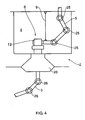
- Fig. 4 shows another embodiment of the transfer pipe 3 and the piping 5 onboard the vessel 2 in comparison with the details shown in fig. 3 .
- the piping 5 is in this embodiment an articulated piping 5 comprising pipe swivel joints 25 within the receiving room 4. Also the transfer pipe 3 is articulated with pipe joints 26.
- Fig. 5 depicts another detail of the system according to the invention.
- the hull 7.of the vessel 2 are, from beneath the receiving room 4 and out to the sides of the vessel formed with recesses or channels 8, for releasing of eventual trapped cryogenic fluid beneath the vessel.
- the evacuation means comprise an opening 30 in the bottom of the receiving room 4, which opening leads to a tank 31.
- a pump 32 and spillage piping 33 for transfer of the cryogenic fluid from the tank back to the system and or to another system.
- Both the receiving room 4 and the tank 31 are formed with insulation voids 36 in the structure forming the receiving room 4 and the tank 31.
- the section of the hull 7 beneath the receiving room is in this embodiment also formed with an insulating cladding 35.
- Fig. 7 depicts another embodiment of the details of the invention which are shown in fig. 3 .
- the cylinder cover 40 extends from the turret means 10 and up to the deck 41 of the vessel 2.
- the embodiment also shows lifting means 9 for eventual lifting of the connection means 6 and or the piping 5 and cylinder cover 40 into contact with the transfer pipe 3 from the other installation, when the buoy 20 and the turret means 10 are brought in contact with and positioned within the receiving means 13 in the vessel 2.
- Fig. 8 depicts a third embodiment. It is referred to the description of fig. 7 and 3 for explanation of similar elements. There is one difference between fig. 7 and fig. 8 in the connection means 6, comprising the swivel means 12 are arranged at or above deck level 41. However, any spillage of cryogenic fluid in the swivel means 6 will still be closed off in that personnel will not have access to the area during transfer, and fluid spillage will run down in to the cylinder cover, and boil off evaporate to the atmosphere.
- Fig. 9 depicts a fourth embodiment, where the turret 10 is arranged as part of the vessel 2.
- the turret 10 is arranged on bearings 11 close to or at the deck level 41, and is anchored to the sea bed by anchor lines 42.
- the connection means 6 comprising the swivel means 12 closed off in a similar manner as the embodiment depicted in fig. 8 .
- connection means 6 may be positioned on the vessel, on the turret and or buoy or partly on the turret and partly on the vessel and brought into contact when the elements are correctly positioned.
- the turret may be a non releasable turret in the vessel.
- the turret arrangement may be in the bow of the vessel.
- the system may comprise all the detail described above or a combination of some of them.
- the receiving room may be filled with an inert gas or nitrogen when the transfer system is used.
- the system may comprise sensors for sensing loss in pressure in the fluid added to the voids, to detect leakage.
- the pipes may be triple mantled, and there may be triple seals, where there is gas added only between two of the mantles or seals or between all or vacuum between some and a fluid between the others.
Landscapes
- Engineering & Computer Science (AREA)
- Mechanical Engineering (AREA)
- General Engineering & Computer Science (AREA)
- Filling Or Discharging Of Gas Storage Vessels (AREA)
- Thermal Insulation (AREA)
- Separation By Low-Temperature Treatments (AREA)
Claims (13)
- System zum Transferieren mindestens eines tiefkalten Fluids zwischen zwei Objekten (1, 2), z.B. einer Anlage (1) und einem Behälter (2), wobei mindestens ein Transferrohr (3), das sich von der Anlage (1) aus erstreckt, sich in einen Aufnahmeraum (4) im Behälter (2) hinein erstreckt, wobei das Transferrohr (3) mit einem Rohrleitungssystem (5) an dem Behälter (2) durch Verbindungsmittel (6) im Aufnahmeraum (4) verbindbar ist, wobei- der Aufnahmeraum (4) schließbar ist,- die Verbindungsmittel (6), und oder mindestens ein Teil der Konstruktion, die den Aufnahmeraum (4) bildet und oder andere Elemente in dem Aufnahmeraum (4), Mittel umfassen, um einem eventuellen Auslaufen des tiefkalten Fluids zu widerstehen,- das System ebenfalls Mittel zum Evakuieren des Aufnahmeraums für eventuell ausgelaufenes Fluid umfasst, dadurch gekennzeichnet, dassmindestens ein Teil der Konstruktion, die den Aufnahmeraum (4) bildet, mit Isolationshohlräumen (36, 22) in der Konstruktion gebildet ist, und oder mit Isolationsmaterial (35) bedeckt ist, und oder mit einem noch kälteresistenteren Material als der Rest des Behälters gebildet ist.
- System gemäß Anspruch 1, dadurch gekennzeichnet, dass das Transferrohr (3) und das Rohrleitungssystem (5) an dem Behälter zumindest doppelt ummantelt sind, mit Vakuum und oder einem speziellen Gas bei einem Druck größer oder gleich dem Druck innerhalb des Rohres (3) oder des Rohrleitungssystems (5) in mindestens einem der Hohlräume zwischen verschiedenen Ummantellungen der Rohre.
- System gemäß Anspruch 2, dadurch gekennzeichnet, dass die Hohlräume (36, 22) in der Konstruktion der Struktur des Aufnahmeraums (4) und oder die Hohlräume in dem doppelt-ummantelten Rohr (3) und oder Rohrleitungssystem (5) mit einem Vakuum und oder einem Gas, z.B. Stickstoff oder einem Inertgas versehen sind.
- System gemäß einem der vorhergehenden Ansprüche, dadurch gekennzeichnet, dass das Rohr von der Anlage durch ein Drehkreuz (10) verläuft, das auf Lagern (11) an/in dem Behälter (2) angeordnet ist, wobei die Verbindungsmittel Schwenkmittel (2) sind, wobei mindestens ein Teil des Drehkreuzes (10) und oder mindestens ein Teil der Konstruktion, die den Aufnahmeraum (4) bildet, mit Hohlräumen (36, 22) mit Vakuum/Gas gebildet ist, oder mit anderen Isolationsmitteln (35) gebildet ist, um eventuellem Auslaufen zu widerstehen.
- System gemäß Anspruch 4, dadurch gekennzeichnet, dass die Lager (11) und oder die Verriegelungsmittel (14) für das Drehkreuz (16) innerhalb des Aufnahmeraums (4) angeordnet sind, und gebildet sind, um eventuellem Auslaufen zu widerstehen.
- System gemäß einem der vorhergehenden Ansprüche, dadurch gekennzeichnet, dass die Mittel zum Evakuieren des Aufnahmeraums (4) eine Öffnung (30) am Boden des Raumes (4) umfassen, die zu einem Ablauftank (31) führt, umfassend eine Pumpe (32) zum Zurückführen von ausgelaufenem Fluid in das System oder zu einem anderen System.
- System gemäß einem der vorhergehenden Ansprüche 4 bis 6, dadurch gekennzeichnet, dass das Drehkreuz (10) lösbar am Behälter (2) angebracht ist.
- System gemäß einem der vorhergehenden Ansprüche 4 bis 7, dadurch gekennzeichnet, dass das Drehkreuz (10) mit einer eingetauchten Boje (20) verbunden ist, die lösbar in Aufnahmemitteln (21) angeordnet ist, angeordnet am Behälter (2) nahe dem Boden der Hülle.
- System gemäß Anspruch 8, dadurch gekennzeichnet, dass mindestens ein Teil des Bereichs um die Aufnahmemittel (21) Isolationsmittel (22) in Form einer Isolationshülle umfasst, und oder Abschnitte der Hülle (17) ausgelegt sind, dass sie einem Auslaufen von tiefkaltem Fluid widerstehen, durch Bilden von Vakuum oder Gashohlräumen und oder Bilden des Abschnitts durch ein kältebeständigeres Material als der Rest des Behälters.
- System gemäß einem der Ansprüche 8 oder 9, dadurch gekennzeichnet, dass die Hülle (7) des Behälters (2) in einem Teil um die Aufnahmemittel (22) herum mit Aussparungen oder Tunneln (8) zur Evakuierung von eventuell eingeschlossener tiefkalter Flüssigkeit unterhalb des Behälters (2) gebildet ist.
- System einem der vorhergehenden Ansprüche, dadurch gekennzeichnet, dass das Rohrleitungssystem (5) innerhalb des Raumes (4) ein bewegliches Rohrleitungssystem zum Verbinden mit dem und Lösen der Verbindung zum Rohr (3) von der Anlage ist.
- System gemäß Anspruch 11, dadurch gekennzeichnet, dass das Rohrleitungssystem (5) in dem Aufnahmeraum (4) durch ein bewegliches Rohrleitungssystem gebildet ist, das Schwenkmittel (12) umfasst.
- System gemäß einem der vorhergehenden Ansprüche, dadurch gekennzeichnet, dass der schließbare Aufnahmeraum (4) beim Transferieren eines tiefkalten Fluids durch das System mit Gas unter einem Druck angefüllt wird, der größer oder gleich dem Druck des tiefkalten Fluids ist.
Applications Claiming Priority (2)
| Application Number | Priority Date | Filing Date | Title |
|---|---|---|---|
| NO20050387A NO336240B1 (no) | 2005-01-25 | 2005-01-25 | Kryogent overføringssystem |
| PCT/NO2006/000031 WO2006080853A1 (en) | 2005-01-25 | 2006-01-24 | Cryogenic transfer system |
Publications (2)
| Publication Number | Publication Date |
|---|---|
| EP1842003A1 EP1842003A1 (de) | 2007-10-10 |
| EP1842003B1 true EP1842003B1 (de) | 2009-07-01 |
Family
ID=35217811
Family Applications (1)
| Application Number | Title | Priority Date | Filing Date |
|---|---|---|---|
| EP06701223A Expired - Lifetime EP1842003B1 (de) | 2005-01-25 | 2006-01-24 | Kryogenes transfersystem |
Country Status (9)
| Country | Link |
|---|---|
| US (1) | US9562647B2 (de) |
| EP (1) | EP1842003B1 (de) |
| CN (1) | CN101120201B (de) |
| AT (1) | ATE435396T1 (de) |
| AU (1) | AU2006209170B2 (de) |
| BR (1) | BRPI0606578A2 (de) |
| DE (1) | DE602006007544D1 (de) |
| NO (1) | NO336240B1 (de) |
| WO (1) | WO2006080853A1 (de) |
Families Citing this family (6)
| Publication number | Priority date | Publication date | Assignee | Title |
|---|---|---|---|---|
| AR078331A1 (es) * | 2009-09-03 | 2011-11-02 | Single Buoy Moorings | Conector estructural que desvia las cargas en direccion contraria al conector de flujo |
| FI125018B (fi) | 2012-02-29 | 2015-04-30 | Wärtsilä Finland Oy | LNG-säiliö |
| EP3487757B1 (de) | 2016-07-25 | 2022-06-29 | National Oilwell Varco Denmark I/S | Erkennung eines parameters in einem flexiblen rohrsystem mit einem revolver |
| JP2023512591A (ja) * | 2020-02-07 | 2023-03-27 | シングル・ブイ・ムアリングズ・インコーポレイテッド | データ転送システムを備えた係留ブイ |
| ES1281261Y (es) * | 2021-09-30 | 2022-01-31 | Saiz Manuel Munoz | Sistema de transporte de energía e hidrógeno |
| CA3210317A1 (en) * | 2021-01-29 | 2022-08-04 | Manuel Munoz Saiz | Energy and hydrogen transport system |
Family Cites Families (38)
| Publication number | Priority date | Publication date | Assignee | Title |
|---|---|---|---|---|
| US2449352A (en) * | 1945-11-27 | 1948-09-14 | Southern Steel Co | Liquefied gas storage and dispensing system |
| US3159004A (en) * | 1961-08-22 | 1964-12-01 | Hydrocarbon Research Inc | Transportation of liquefied natural gas |
| BE643861A (de) * | 1963-02-20 | 1900-01-01 | ||
| US3428013A (en) * | 1967-11-03 | 1969-02-18 | Shell Oil Co | Apparatus for transporting liquefied gases |
| NL152649B (nl) * | 1970-01-28 | 1977-03-15 | Shell Int Research | Pijpleiding of pijpleidingsectie voor het transport van een fluidum bij cryogene temperaturen, bijvoorbeeld vloeibaar aardgas. |
| FR2135575B1 (de) * | 1971-05-05 | 1973-07-13 | Liquid Gas Anlagen Union | |
| US3875886A (en) * | 1972-04-28 | 1975-04-08 | Gen Dynamics Corp | Liquified-gas ship |
| DE2630342A1 (de) | 1976-07-06 | 1978-01-12 | Rudolf Dr Ing Vogel | Verfahren zum betrieb eines auf dem meeresboden stationierten speichers und einrichtungen dazu |
| GB1599491A (en) * | 1978-01-07 | 1981-10-07 | Fmc Corp | Pipe swivel joints |
| US4315408A (en) * | 1980-12-18 | 1982-02-16 | Amtel, Inc. | Offshore liquified gas transfer system |
| EP0157186B1 (de) | 1984-04-03 | 1990-01-10 | Preh-Werke GmbH & Co. KG | Arretierbarer Schiebeschalter |
| US4604961A (en) * | 1984-06-11 | 1986-08-12 | Exxon Production Research Co. | Vessel mooring system |
| US5194164A (en) * | 1991-03-04 | 1993-03-16 | Adams George W | Inclined-plane oil skimmers |
| US5146863A (en) * | 1991-10-21 | 1992-09-15 | The United States Of America As Represented By The Secretary Of The Navy | Air cushion displacement hull water vehicle |
| GB2277070B (en) * | 1991-11-27 | 1995-08-02 | Norske Stats Oljeselskap | Method and system for connecting a loading buoy to a floating vessel |
| US5305703A (en) * | 1992-12-31 | 1994-04-26 | Jens Korsgaard | Vessel mooring system |
| DE4320759A1 (de) | 1993-02-27 | 1995-01-05 | Gfd Ingenieur Und Beratungsges | Verfahren und Anlage zur Rest-Entleerung und Entgasung von Kesselwagen und Tanks für den Transport bzw. für die Lagerung von Flüssiggas und zur Wiedergewinnung des Flüssiggases |
| NO177778C (no) * | 1993-07-06 | 1995-11-22 | Statoil As | System for offshore-produksjon av hydrokarboner |
| US5339760A (en) * | 1993-09-20 | 1994-08-23 | Jens Korsgaard | Apparatus for securing a vessel to a submersible mooring buoy |
| NO180469B1 (no) * | 1994-12-08 | 1997-05-12 | Statoil Petroleum As | Fremgangsmåte og system for fremstilling av flytendegjort naturgass til havs |
| NO308786B1 (no) * | 1995-06-22 | 2000-10-30 | Norske Stats Oljeselskap | Roterende koplingsanordning med integrert LNG-løp |
| US5762342A (en) * | 1996-05-03 | 1998-06-09 | Durametallic Corporation | Mechanical seal with controller for regulating face contact pressure |
| NO315194B1 (no) | 1998-01-30 | 2003-07-28 | Navion As | Fremgangsmåte og system for eksport av LNG og kondensat fra et flytende produksjons-, lagrings- og lossefartöy |
| EP0947464A1 (de) * | 1998-04-01 | 1999-10-06 | Single Buoy Moorings Inc. | Ladeausleger für Flüssigkeiten mit koaxialen Flüssigkeitsleitungen |
| CA2346824C (en) | 1999-03-03 | 2003-05-06 | Fmc Technologies, Inc. | Explosion prevention system for internal turret mooring system |
| US6367522B1 (en) * | 1999-07-29 | 2002-04-09 | Fci Products, Inc. | Suspended marina/watercraft fueling system and method |
| NO312715B2 (no) | 1999-10-27 | 2002-06-24 | Statoil Asa | System for offshore overforing av flytendegjort naturgass |
| US6298671B1 (en) * | 2000-06-14 | 2001-10-09 | Bp Amoco Corporation | Method for producing, transporting, offloading, storing and distributing natural gas to a marketplace |
| US6793740B1 (en) * | 2000-10-12 | 2004-09-21 | General Electric Company | Method for cleaning pressurized containers containing moisture sensitive chemicals |
| US6443166B1 (en) * | 2000-10-12 | 2002-09-03 | General Electric Company | Method of cleaning a pressurized container |
| US6926776B1 (en) * | 2000-10-12 | 2005-08-09 | General Electric Company | Method for cleaning pressurized containers containing chlorine gas or sulfur dioxide gas |
| US6622758B2 (en) * | 2001-02-08 | 2003-09-23 | Chart Inc. | Interlock for cryogenic liquid off-loading systems |
| NZ533488A (en) * | 2001-12-12 | 2005-04-29 | Single Buoy Moorings | Weathervaning LNG offloading system |
| DE10214667A1 (de) | 2002-04-03 | 2003-10-30 | Messer Griesheim Gmbh | Umfüllschlauch |
| FR2847245B1 (fr) * | 2002-11-19 | 2005-06-24 | Coflexip | Installation de transfert de gaz liquefie et son utilisation |
| GB2396138B (en) * | 2002-12-12 | 2004-10-27 | Bluewater Terminal Systems Nv | Off-shore mooring and fluid transfer system |
| US7331302B2 (en) * | 2004-06-18 | 2008-02-19 | Stanley Secretan | Quick close security door system |
| US7717762B2 (en) * | 2006-04-24 | 2010-05-18 | Sofec, Inc. | Detachable mooring system with bearings mounted on submerged buoy |
-
2005
- 2005-01-25 NO NO20050387A patent/NO336240B1/no unknown
-
2006
- 2006-01-24 AU AU2006209170A patent/AU2006209170B2/en not_active Ceased
- 2006-01-24 WO PCT/NO2006/000031 patent/WO2006080853A1/en not_active Ceased
- 2006-01-24 US US11/795,472 patent/US9562647B2/en active Active
- 2006-01-24 AT AT06701223T patent/ATE435396T1/de not_active IP Right Cessation
- 2006-01-24 CN CN2006800031520A patent/CN101120201B/zh not_active Expired - Fee Related
- 2006-01-24 EP EP06701223A patent/EP1842003B1/de not_active Expired - Lifetime
- 2006-01-24 DE DE602006007544T patent/DE602006007544D1/de not_active Expired - Lifetime
- 2006-01-24 BR BRPI0606578-3A patent/BRPI0606578A2/pt active Search and Examination
Also Published As
| Publication number | Publication date |
|---|---|
| ATE435396T1 (de) | 2009-07-15 |
| DE602006007544D1 (de) | 2009-08-13 |
| NO336240B1 (no) | 2015-06-29 |
| US20090071173A1 (en) | 2009-03-19 |
| CN101120201A (zh) | 2008-02-06 |
| NO20050387L (no) | 2006-07-26 |
| WO2006080853A1 (en) | 2006-08-03 |
| AU2006209170A1 (en) | 2006-08-03 |
| US9562647B2 (en) | 2017-02-07 |
| NO20050387D0 (no) | 2005-01-25 |
| BRPI0606578A2 (pt) | 2009-11-24 |
| CN101120201B (zh) | 2010-06-09 |
| AU2006209170A2 (en) | 2006-08-03 |
| AU2006209170B2 (en) | 2011-06-30 |
| EP1842003A1 (de) | 2007-10-10 |
Similar Documents
| Publication | Publication Date | Title |
|---|---|---|
| US4365576A (en) | Offshore submarine storage facility for highly chilled liquified gases | |
| JP5009802B2 (ja) | 極低温流体海中移送システム | |
| JP4410938B2 (ja) | 極低温流体の搬送方法および装置 | |
| KR101653892B1 (ko) | 외부 컨테이너들을 구비하는 해양에 설치된 지지체 | |
| CN111727343B (zh) | 用于储存和运输液化气体的设施 | |
| US4232983A (en) | Offshore submarine storage facility for highly chilled liquified gases | |
| US3984059A (en) | Liquid handling | |
| EP1428748B1 (de) | Offshore Anker und Fluidtransfer System | |
| EP2228294A1 (de) | Gefäß zum Transport von verflüssigtem Erdgas | |
| KR20070085870A (ko) | 액화천연가스 부유식 저장 재기화 설비 | |
| KR20150004764A (ko) | 장대한 해상 부체 설비 | |
| CN102149598A (zh) | 用于储存气体的浮动单元 | |
| NO335698B1 (no) | Overføringsinstallasjon for kondensert gass og bruk av installasjonen | |
| EP1842003B1 (de) | Kryogenes transfersystem | |
| CN113968313A (zh) | 用于对液化气体的储存罐进行加热的系统和方法 | |
| CN111788429A (zh) | 用于在船舶上储存和运输低温流体的系统 | |
| WO2022145319A1 (ja) | 船舶 | |
| RU2200109C1 (ru) | Комплекс для передачи жидкого груза на танкер (варианты) | |
| CN116265802A (zh) | 用于贮存液化气体的包括罐和穹顶状结构的设施 | |
| RU2852112C2 (ru) | Система и способ нагрева резервуара для хранения сжиженного газа | |
| RU2378149C1 (ru) | Комплекс для передачи жидкого груза, преимущественно нефти, на танкер | |
| RU2783569C2 (ru) | Установка для хранения и транспортировки криогенной текучей среды на судне | |
| KR20230040144A (ko) | 액화수소 저장용기를 포함하는 해상 운송 수단 | |
| GB2070219A (en) | Improvements in or relating to a storage facility | |
| HK1182065B (en) | Buoyant body, in particular container ship |
Legal Events
| Date | Code | Title | Description |
|---|---|---|---|
| PUAI | Public reference made under article 153(3) epc to a published international application that has entered the european phase |
Free format text: ORIGINAL CODE: 0009012 |
|
| 17P | Request for examination filed |
Effective date: 20070803 |
|
| AK | Designated contracting states |
Kind code of ref document: A1 Designated state(s): AT BE BG CH CY CZ DE DK EE ES FI FR GB GR HU IE IS IT LI LT LU LV MC NL PL PT RO SE SI SK TR |
|
| DAX | Request for extension of the european patent (deleted) | ||
| GRAP | Despatch of communication of intention to grant a patent |
Free format text: ORIGINAL CODE: EPIDOSNIGR1 |
|
| GRAS | Grant fee paid |
Free format text: ORIGINAL CODE: EPIDOSNIGR3 |
|
| GRAA | (expected) grant |
Free format text: ORIGINAL CODE: 0009210 |
|
| AK | Designated contracting states |
Kind code of ref document: B1 Designated state(s): AT BE BG CH CY CZ DE DK EE ES FI FR GB GR HU IE IS IT LI LT LU LV MC NL PL PT RO SE SI SK TR |
|
| REG | Reference to a national code |
Ref country code: GB Ref legal event code: FG4D |
|
| REG | Reference to a national code |
Ref country code: CH Ref legal event code: EP |
|
| REG | Reference to a national code |
Ref country code: IE Ref legal event code: FG4D |
|
| REF | Corresponds to: |
Ref document number: 602006007544 Country of ref document: DE Date of ref document: 20090813 Kind code of ref document: P |
|
| PG25 | Lapsed in a contracting state [announced via postgrant information from national office to epo] |
Ref country code: SI Free format text: LAPSE BECAUSE OF FAILURE TO SUBMIT A TRANSLATION OF THE DESCRIPTION OR TO PAY THE FEE WITHIN THE PRESCRIBED TIME-LIMIT Effective date: 20090701 |
|
| NLV1 | Nl: lapsed or annulled due to failure to fulfill the requirements of art. 29p and 29m of the patents act | ||
| PG25 | Lapsed in a contracting state [announced via postgrant information from national office to epo] |
Ref country code: ES Free format text: LAPSE BECAUSE OF FAILURE TO SUBMIT A TRANSLATION OF THE DESCRIPTION OR TO PAY THE FEE WITHIN THE PRESCRIBED TIME-LIMIT Effective date: 20091012 Ref country code: FI Free format text: LAPSE BECAUSE OF FAILURE TO SUBMIT A TRANSLATION OF THE DESCRIPTION OR TO PAY THE FEE WITHIN THE PRESCRIBED TIME-LIMIT Effective date: 20090701 Ref country code: AT Free format text: LAPSE BECAUSE OF FAILURE TO SUBMIT A TRANSLATION OF THE DESCRIPTION OR TO PAY THE FEE WITHIN THE PRESCRIBED TIME-LIMIT Effective date: 20090701 Ref country code: EE Free format text: LAPSE BECAUSE OF FAILURE TO SUBMIT A TRANSLATION OF THE DESCRIPTION OR TO PAY THE FEE WITHIN THE PRESCRIBED TIME-LIMIT Effective date: 20090701 Ref country code: IS Free format text: LAPSE BECAUSE OF FAILURE TO SUBMIT A TRANSLATION OF THE DESCRIPTION OR TO PAY THE FEE WITHIN THE PRESCRIBED TIME-LIMIT Effective date: 20091101 Ref country code: SE Free format text: LAPSE BECAUSE OF FAILURE TO SUBMIT A TRANSLATION OF THE DESCRIPTION OR TO PAY THE FEE WITHIN THE PRESCRIBED TIME-LIMIT Effective date: 20090701 Ref country code: LT Free format text: LAPSE BECAUSE OF FAILURE TO SUBMIT A TRANSLATION OF THE DESCRIPTION OR TO PAY THE FEE WITHIN THE PRESCRIBED TIME-LIMIT Effective date: 20090701 |
|
| PG25 | Lapsed in a contracting state [announced via postgrant information from national office to epo] |
Ref country code: LV Free format text: LAPSE BECAUSE OF FAILURE TO SUBMIT A TRANSLATION OF THE DESCRIPTION OR TO PAY THE FEE WITHIN THE PRESCRIBED TIME-LIMIT Effective date: 20090701 Ref country code: PL Free format text: LAPSE BECAUSE OF FAILURE TO SUBMIT A TRANSLATION OF THE DESCRIPTION OR TO PAY THE FEE WITHIN THE PRESCRIBED TIME-LIMIT Effective date: 20090701 Ref country code: NL Free format text: LAPSE BECAUSE OF FAILURE TO SUBMIT A TRANSLATION OF THE DESCRIPTION OR TO PAY THE FEE WITHIN THE PRESCRIBED TIME-LIMIT Effective date: 20090701 |
|
| PG25 | Lapsed in a contracting state [announced via postgrant information from national office to epo] |
Ref country code: BG Free format text: LAPSE BECAUSE OF FAILURE TO SUBMIT A TRANSLATION OF THE DESCRIPTION OR TO PAY THE FEE WITHIN THE PRESCRIBED TIME-LIMIT Effective date: 20091001 Ref country code: PT Free format text: LAPSE BECAUSE OF FAILURE TO SUBMIT A TRANSLATION OF THE DESCRIPTION OR TO PAY THE FEE WITHIN THE PRESCRIBED TIME-LIMIT Effective date: 20091102 |
|
| PG25 | Lapsed in a contracting state [announced via postgrant information from national office to epo] |
Ref country code: RO Free format text: LAPSE BECAUSE OF FAILURE TO SUBMIT A TRANSLATION OF THE DESCRIPTION OR TO PAY THE FEE WITHIN THE PRESCRIBED TIME-LIMIT Effective date: 20090701 Ref country code: DK Free format text: LAPSE BECAUSE OF FAILURE TO SUBMIT A TRANSLATION OF THE DESCRIPTION OR TO PAY THE FEE WITHIN THE PRESCRIBED TIME-LIMIT Effective date: 20090701 Ref country code: CZ Free format text: LAPSE BECAUSE OF FAILURE TO SUBMIT A TRANSLATION OF THE DESCRIPTION OR TO PAY THE FEE WITHIN THE PRESCRIBED TIME-LIMIT Effective date: 20090701 |
|
| PLBE | No opposition filed within time limit |
Free format text: ORIGINAL CODE: 0009261 |
|
| STAA | Information on the status of an ep patent application or granted ep patent |
Free format text: STATUS: NO OPPOSITION FILED WITHIN TIME LIMIT |
|
| PG25 | Lapsed in a contracting state [announced via postgrant information from national office to epo] |
Ref country code: SK Free format text: LAPSE BECAUSE OF FAILURE TO SUBMIT A TRANSLATION OF THE DESCRIPTION OR TO PAY THE FEE WITHIN THE PRESCRIBED TIME-LIMIT Effective date: 20090701 Ref country code: BE Free format text: LAPSE BECAUSE OF FAILURE TO SUBMIT A TRANSLATION OF THE DESCRIPTION OR TO PAY THE FEE WITHIN THE PRESCRIBED TIME-LIMIT Effective date: 20090701 |
|
| 26N | No opposition filed |
Effective date: 20100406 |
|
| PG25 | Lapsed in a contracting state [announced via postgrant information from national office to epo] |
Ref country code: MC Free format text: LAPSE BECAUSE OF NON-PAYMENT OF DUE FEES Effective date: 20100131 |
|
| REG | Reference to a national code |
Ref country code: CH Ref legal event code: PL |
|
| PG25 | Lapsed in a contracting state [announced via postgrant information from national office to epo] |
Ref country code: LI Free format text: LAPSE BECAUSE OF NON-PAYMENT OF DUE FEES Effective date: 20100131 Ref country code: CH Free format text: LAPSE BECAUSE OF NON-PAYMENT OF DUE FEES Effective date: 20100131 Ref country code: GR Free format text: LAPSE BECAUSE OF FAILURE TO SUBMIT A TRANSLATION OF THE DESCRIPTION OR TO PAY THE FEE WITHIN THE PRESCRIBED TIME-LIMIT Effective date: 20091002 |
|
| PG25 | Lapsed in a contracting state [announced via postgrant information from national office to epo] |
Ref country code: IE Free format text: LAPSE BECAUSE OF NON-PAYMENT OF DUE FEES Effective date: 20100124 |
|
| PG25 | Lapsed in a contracting state [announced via postgrant information from national office to epo] |
Ref country code: IT Free format text: LAPSE BECAUSE OF FAILURE TO SUBMIT A TRANSLATION OF THE DESCRIPTION OR TO PAY THE FEE WITHIN THE PRESCRIBED TIME-LIMIT Effective date: 20090701 |
|
| PG25 | Lapsed in a contracting state [announced via postgrant information from national office to epo] |
Ref country code: CY Free format text: LAPSE BECAUSE OF FAILURE TO SUBMIT A TRANSLATION OF THE DESCRIPTION OR TO PAY THE FEE WITHIN THE PRESCRIBED TIME-LIMIT Effective date: 20090701 |
|
| PG25 | Lapsed in a contracting state [announced via postgrant information from national office to epo] |
Ref country code: LU Free format text: LAPSE BECAUSE OF NON-PAYMENT OF DUE FEES Effective date: 20100124 Ref country code: HU Free format text: LAPSE BECAUSE OF FAILURE TO SUBMIT A TRANSLATION OF THE DESCRIPTION OR TO PAY THE FEE WITHIN THE PRESCRIBED TIME-LIMIT Effective date: 20100102 |
|
| PG25 | Lapsed in a contracting state [announced via postgrant information from national office to epo] |
Ref country code: TR Free format text: LAPSE BECAUSE OF FAILURE TO SUBMIT A TRANSLATION OF THE DESCRIPTION OR TO PAY THE FEE WITHIN THE PRESCRIBED TIME-LIMIT Effective date: 20090701 |
|
| PGFP | Annual fee paid to national office [announced via postgrant information from national office to epo] |
Ref country code: FR Payment date: 20141226 Year of fee payment: 10 |
|
| PGFP | Annual fee paid to national office [announced via postgrant information from national office to epo] |
Ref country code: DE Payment date: 20160127 Year of fee payment: 11 |
|
| REG | Reference to a national code |
Ref country code: FR Ref legal event code: ST Effective date: 20160930 |
|
| PG25 | Lapsed in a contracting state [announced via postgrant information from national office to epo] |
Ref country code: FR Free format text: LAPSE BECAUSE OF NON-PAYMENT OF DUE FEES Effective date: 20160201 |
|
| REG | Reference to a national code |
Ref country code: DE Ref legal event code: R119 Ref document number: 602006007544 Country of ref document: DE |
|
| PG25 | Lapsed in a contracting state [announced via postgrant information from national office to epo] |
Ref country code: DE Free format text: LAPSE BECAUSE OF NON-PAYMENT OF DUE FEES Effective date: 20170801 |
|
| PGFP | Annual fee paid to national office [announced via postgrant information from national office to epo] |
Ref country code: GB Payment date: 20241205 Year of fee payment: 20 |
|
| REG | Reference to a national code |
Ref country code: GB Ref legal event code: PE20 Expiry date: 20260123 |