EP1838511B1 - Method for the production of a composite molded part made of plastic, and use thereof - Google Patents
Method for the production of a composite molded part made of plastic, and use thereof Download PDFInfo
- Publication number
- EP1838511B1 EP1838511B1 EP05818703.0A EP05818703A EP1838511B1 EP 1838511 B1 EP1838511 B1 EP 1838511B1 EP 05818703 A EP05818703 A EP 05818703A EP 1838511 B1 EP1838511 B1 EP 1838511B1
- Authority
- EP
- European Patent Office
- Prior art keywords
- mould
- lacquer
- film
- moulding
- cavity
- Prior art date
- Legal status (The legal status is an assumption and is not a legal conclusion. Google has not performed a legal analysis and makes no representation as to the accuracy of the status listed.)
- Active
Links
- 229920003023 plastic Polymers 0.000 title claims description 25
- 239000004033 plastic Substances 0.000 title claims description 23
- 239000002131 composite material Substances 0.000 title claims description 14
- 238000000034 method Methods 0.000 title claims description 14
- 238000004519 manufacturing process Methods 0.000 title claims description 7
- 238000000465 moulding Methods 0.000 claims description 19
- 239000011248 coating agent Substances 0.000 claims description 12
- 238000000576 coating method Methods 0.000 claims description 12
- 239000004922 lacquer Substances 0.000 claims description 11
- 229920000515 polycarbonate Polymers 0.000 claims description 10
- 229920003229 poly(methyl methacrylate) Polymers 0.000 claims description 9
- 239000004417 polycarbonate Substances 0.000 claims description 7
- 239000004926 polymethyl methacrylate Substances 0.000 claims description 7
- 229920000638 styrene acrylonitrile Polymers 0.000 claims description 7
- 238000001816 cooling Methods 0.000 claims description 5
- 229920001577 copolymer Polymers 0.000 claims description 5
- 238000002347 injection Methods 0.000 claims description 5
- 239000007924 injection Substances 0.000 claims description 5
- 239000000203 mixture Substances 0.000 claims description 5
- SCUZVMOVTVSBLE-UHFFFAOYSA-N prop-2-enenitrile;styrene Chemical compound C=CC#N.C=CC1=CC=CC=C1 SCUZVMOVTVSBLE-UHFFFAOYSA-N 0.000 claims description 5
- 229920002647 polyamide Polymers 0.000 claims description 4
- 239000004952 Polyamide Substances 0.000 claims description 3
- 239000003795 chemical substances by application Substances 0.000 claims description 3
- UHESRSKEBRADOO-UHFFFAOYSA-N ethyl carbamate;prop-2-enoic acid Chemical compound OC(=O)C=C.CCOC(N)=O UHESRSKEBRADOO-UHFFFAOYSA-N 0.000 claims description 3
- 229920001296 polysiloxane Polymers 0.000 claims description 3
- -1 polysiloxanes Polymers 0.000 claims description 3
- 239000004814 polyurethane Substances 0.000 claims description 3
- 229920002635 polyurethane Polymers 0.000 claims description 3
- 239000003973 paint Substances 0.000 description 14
- 239000010410 layer Substances 0.000 description 9
- 239000002985 plastic film Substances 0.000 description 9
- 229920006255 plastic film Polymers 0.000 description 9
- 239000000463 material Substances 0.000 description 6
- 239000002184 metal Substances 0.000 description 4
- 229910052751 metal Inorganic materials 0.000 description 4
- 229920000642 polymer Polymers 0.000 description 4
- JDCCCHBBXRQRGU-UHFFFAOYSA-N 5-phenylpenta-2,4-dienenitrile Chemical compound N#CC=CC=CC1=CC=CC=C1 JDCCCHBBXRQRGU-UHFFFAOYSA-N 0.000 description 2
- UKLDJPRMSDWDSL-UHFFFAOYSA-L [dibutyl(dodecanoyloxy)stannyl] dodecanoate Chemical compound CCCCCCCCCCCC(=O)O[Sn](CCCC)(CCCC)OC(=O)CCCCCCCCCCC UKLDJPRMSDWDSL-UHFFFAOYSA-L 0.000 description 2
- 125000001931 aliphatic group Chemical group 0.000 description 2
- 239000012975 dibutyltin dilaurate Substances 0.000 description 2
- 239000004425 Makrolon Substances 0.000 description 1
- 229920004089 Makrolon® AL2647 Polymers 0.000 description 1
- 239000004972 Polyurethane varnish Substances 0.000 description 1
- 229910000831 Steel Inorganic materials 0.000 description 1
- 230000006750 UV protection Effects 0.000 description 1
- 238000004873 anchoring Methods 0.000 description 1
- 239000011247 coating layer Substances 0.000 description 1
- 238000010276 construction Methods 0.000 description 1
- 238000007786 electrostatic charging Methods 0.000 description 1
- 239000011888 foil Substances 0.000 description 1
- 238000001746 injection moulding Methods 0.000 description 1
- 150000002739 metals Chemical class 0.000 description 1
- 229920006289 polycarbonate film Polymers 0.000 description 1
- 229920005906 polyester polyol Polymers 0.000 description 1
- 239000005056 polyisocyanate Substances 0.000 description 1
- 229920001228 polyisocyanate Polymers 0.000 description 1
- 239000011527 polyurethane coating Substances 0.000 description 1
- 239000011241 protective layer Substances 0.000 description 1
- 238000007650 screen-printing Methods 0.000 description 1
- 230000003068 static effect Effects 0.000 description 1
- 239000010959 steel Substances 0.000 description 1
- 239000011145 styrene acrylonitrile resin Substances 0.000 description 1
- 239000000758 substrate Substances 0.000 description 1
- 229920001187 thermosetting polymer Polymers 0.000 description 1
Images
Classifications
-
- B—PERFORMING OPERATIONS; TRANSPORTING
- B29—WORKING OF PLASTICS; WORKING OF SUBSTANCES IN A PLASTIC STATE IN GENERAL
- B29C—SHAPING OR JOINING OF PLASTICS; SHAPING OF MATERIAL IN A PLASTIC STATE, NOT OTHERWISE PROVIDED FOR; AFTER-TREATMENT OF THE SHAPED PRODUCTS, e.g. REPAIRING
- B29C45/00—Injection moulding, i.e. forcing the required volume of moulding material through a nozzle into a closed mould; Apparatus therefor
- B29C45/16—Making multilayered or multicoloured articles
- B29C45/1671—Making multilayered or multicoloured articles with an insert
-
- B—PERFORMING OPERATIONS; TRANSPORTING
- B29—WORKING OF PLASTICS; WORKING OF SUBSTANCES IN A PLASTIC STATE IN GENERAL
- B29C—SHAPING OR JOINING OF PLASTICS; SHAPING OF MATERIAL IN A PLASTIC STATE, NOT OTHERWISE PROVIDED FOR; AFTER-TREATMENT OF THE SHAPED PRODUCTS, e.g. REPAIRING
- B29C45/00—Injection moulding, i.e. forcing the required volume of moulding material through a nozzle into a closed mould; Apparatus therefor
- B29C45/14—Injection moulding, i.e. forcing the required volume of moulding material through a nozzle into a closed mould; Apparatus therefor incorporating preformed parts or layers, e.g. injection moulding around inserts or for coating articles
-
- B—PERFORMING OPERATIONS; TRANSPORTING
- B29—WORKING OF PLASTICS; WORKING OF SUBSTANCES IN A PLASTIC STATE IN GENERAL
- B29C—SHAPING OR JOINING OF PLASTICS; SHAPING OF MATERIAL IN A PLASTIC STATE, NOT OTHERWISE PROVIDED FOR; AFTER-TREATMENT OF THE SHAPED PRODUCTS, e.g. REPAIRING
- B29C45/00—Injection moulding, i.e. forcing the required volume of moulding material through a nozzle into a closed mould; Apparatus therefor
- B29C45/16—Making multilayered or multicoloured articles
- B29C45/1679—Making multilayered or multicoloured articles applying surface layers onto injection-moulded substrates inside the mould cavity, e.g. in-mould coating [IMC]
-
- B—PERFORMING OPERATIONS; TRANSPORTING
- B29—WORKING OF PLASTICS; WORKING OF SUBSTANCES IN A PLASTIC STATE IN GENERAL
- B29C—SHAPING OR JOINING OF PLASTICS; SHAPING OF MATERIAL IN A PLASTIC STATE, NOT OTHERWISE PROVIDED FOR; AFTER-TREATMENT OF THE SHAPED PRODUCTS, e.g. REPAIRING
- B29C45/00—Injection moulding, i.e. forcing the required volume of moulding material through a nozzle into a closed mould; Apparatus therefor
- B29C45/14—Injection moulding, i.e. forcing the required volume of moulding material through a nozzle into a closed mould; Apparatus therefor incorporating preformed parts or layers, e.g. injection moulding around inserts or for coating articles
- B29C45/14778—Injection moulding, i.e. forcing the required volume of moulding material through a nozzle into a closed mould; Apparatus therefor incorporating preformed parts or layers, e.g. injection moulding around inserts or for coating articles the article consisting of a material with particular properties, e.g. porous, brittle
- B29C45/14811—Multilayered articles
-
- B—PERFORMING OPERATIONS; TRANSPORTING
- B29—WORKING OF PLASTICS; WORKING OF SUBSTANCES IN A PLASTIC STATE IN GENERAL
- B29K—INDEXING SCHEME ASSOCIATED WITH SUBCLASSES B29B, B29C OR B29D, RELATING TO MOULDING MATERIALS OR TO MATERIALS FOR MOULDS, REINFORCEMENTS, FILLERS OR PREFORMED PARTS, e.g. INSERTS
- B29K2705/00—Use of metals, their alloys or their compounds, for preformed parts, e.g. for inserts
Landscapes
- Engineering & Computer Science (AREA)
- Manufacturing & Machinery (AREA)
- Mechanical Engineering (AREA)
- Injection Moulding Of Plastics Or The Like (AREA)
Description
Die Erfindung betrifft ein Verfahren zur Herstellung eines Verbundformteiles aus mehreren Kunststoffschichten und dessen Verwendung.The invention relates to a method for producing a composite molded part from a plurality of plastic layers and its use.
Aus der Literatur sind Verbunde aus Metallfolien und Polymeren bekannt, wobei diese Schichten entweder verklebt und/oder durch Temperatur und Druck miteinander verbunden werden. Nachteil dieser Verbundsysteme ist, dass Wärme und Druck zur Verbindung der Schichten in einem separaten Schritt erzeugt werden müssen. Darüber hinaus ist es häufig erforderlich, die Schichtkanten nachzuarbeiten. Befestigungselemente und dergleichen müssen nachträglich in einem separaten Schritt angebracht werden.From the literature composites of metal foils and polymers are known, these layers are either glued and / or connected to each other by temperature and pressure. Disadvantage of these composite systems is that heat and pressure to connect the layers must be generated in a separate step. In addition, it is often necessary to rework the layer edges. Fasteners and the like must be retrofitted in a separate step.
Das Hinterspritzen von Kunststoffteilen scheint aus dem Stand der Technik bekannt:
Aufgabe war es daher, ein Verfahren zur Verfügung zu stellen, mit dem es auf technisch einfache und kostengünstige Weise möglich ist, Verbundformteile aus mehreren Schichten herzustellen, so dass die Schichten haftend miteinander verbunden sind und gegebenenfalls weitere Elemente, wie beispielsweise Befestigungselemente, bei der Herstellung direkt mit angebracht werden können.The object was therefore to provide a method with which it is possible in a technically simple and cost-effective manner to produce composite moldings of several layers, so that the layers are adhesively bonded together and optionally other elements, such as fasteners in the manufacture can be attached directly with.
Diese Aufgabe konnte durch das erfindungsgemäße Verfahren gelöst werden. Gegenstand der Erfindung ist ein Verfahren zur Herstellung eines Verbundteiles aus mehreren Schichten, wobei
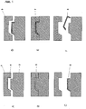
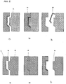
- a) eine Kunststofffolie in eine erste Hälfte eines geöffneten Spritzgießwerkzeugs eingelegt wird, wobei als Kunststoff für die Folie Polycarbonat, Polymethylmethacrylat, Styrolacrylnitril, ein Cycloolefincopolymer, transparentes Polyamid oder Blends dieser Kunststoffe eingesetzt sind,
- b) das Werkzeug geschlossen wird, indem die zweite Hälfte des Werkzeugs auf der ersten Hälfte angebracht wird, so dass ein Hohlraum gebildet wird,
- c) die Folie im Werkzeug mit Kunststoff zur Erzeugung eines Formteils haftend hinterspritzt wird, wobei der zum Hinterspritzen verwendete Kunststoff Polycarbonat, Styrolacrylnitril, ein Cycloolefincopolymer oder Polymethylmethacrylat ist,
- d) das Werkzeug nach Abkühlung geöffnet wird und eine der beiden Hälften des Werkzeugs entfernt wird, wobei das Formteil aus c) in der anderen Hälfte verbleibt,
- e) danach das Werkzeug mittels einer Werkzeughälfte, die gegebenenfalls mit externem Formtrennmittel versehen ist, erneut geschlossen wird, und dabei eine Kavität zwischen der Wand dieser Werkzeughälfte und dem Formteil erzeugt wird, wobei die Kavität auf der Seite des Formteils liegt, die der Seite mit der Kunststofffolie gegenüberliegt,
- f) in die Kavität ein Lack eingespritzt wird, wobei der Lack ein Urethanacrylat-, ein 2-Komponenten-Polyurethanlack oder ein Lack auf Basis von Polysiloxanen ist,
- g) das Werkzeug nach Aushärtung des Lackes geöffnet und das lackierte Formteil entnommen wird.
- a) a plastic film is inserted into a first half of an opened injection mold, wherein the plastic used for the film is polycarbonate, polymethylmethacrylate, styrene-acrylonitrile, a cycloolefin copolymer, transparent polyamide or blends of these plastics,
- b) the tool is closed by attaching the second half of the tool to the first half so as to form a cavity,
- c) the film in the mold is back-injected with plastic for producing a molded part, the plastic used for injection molding being polycarbonate, styrene-acrylonitrile, a cycloolefin copolymer or polymethyl methacrylate,
- d) the tool is opened after cooling and one of the two halves of the tool is removed, the molding of c) remaining in the other half,
- e) thereafter the tool is closed again by means of a mold half optionally provided with external mold release means, thereby creating a cavity between the wall of said mold half and the mold part, the cavity lying on the side of the mold part facing the side opposite the plastic film,
- f) a lacquer is injected into the cavity, the lacquer being a urethane acrylate, a 2-component polyurethane lacquer or a polysiloxane-based lacquer,
- g) the tool is opened after curing of the paint and the painted part is removed.
Die eingesetzte Folie kann vorzugsweise auf mindestens einer Seite mindestens teilweise beschichtet sein.The film used may preferably be at least partially coated on at least one side.
Das erfindungsgemäße Verfahren kann so durchgeführt werden, dass die beschichtete Folie in Schritt a) so in die Werkzeughälfte eingelegt wird, dass entweder die Beschichtung zur Werkzeugwand gerichtet ist oder dass die Beschichtung von der Wand der Werkzeughälfte abgewandt ist.The inventive method can be carried out so that the coated film is inserted in step a) in the mold half that either the coating is directed to the mold wall or that the coating is remote from the wall of the mold half.
Die eingesetzte Kunststofffolie ist bevorzugt 0,175 bis 3,00 mm dick. Die Folie kann mittels Siebdruck, durch Vakuum oder auch durch andere bekannte Beschichtungstechniken beschichtet werden. Als Beschichtungsmaterialien können Farben, Metalle oder dergleichen eingesetzt werden.The plastic film used is preferably 0.175 to 3.00 mm thick. The film can be coated by screen printing, by vacuum or by other known coating techniques. As coating materials, paints, metals or the like can be used.
Anstelle einer einfachen Kunststofffolie mit oder ohne Beschichtung kann auch ein Folienverbund eingesetzt werden. Die einfachste Ausführungsform ist ein dreischichtiger Aufbau aus einer Kunststofffolie, beispielsweise einer Metallschicht und daran sich anschließend wieder eine Kunststofffolie. Der Vorteil eines derartigen Aufbaus besteht darin, dass die Beschichtung geschützt ist.Instead of a simple plastic film with or without coating, it is also possible to use a film composite. The simplest embodiment is a three-layer structure made of a plastic film, for example a metal layer and then again a plastic film. The advantage of such a construction is that the coating is protected.
Damit die Folie, die in die eine Hälfte des offenen Werkzeugs eingelegt wird, nicht verrutscht, wird sie vorzugsweise durch Vakuum, statische Aufladung oder durch mechanische Verankerung in der Werkzeughälfte fixiert.In order for the film, which is inserted in one half of the open tool, does not slip, it is preferably fixed by vacuum, static charge or by mechanical anchoring in the mold half.
Wird die Folie so in die Werkzeughälfte eingelegt, dass die Beschichtung nach innen zeigt, wird diese Beschichtung beim Hinterspritzen direkt mit dem eingespritzten Kunststoff bedeckt. Wird hingegen die Folie so in das Werkzeug eingelegt, dass die Beschichtung nach außen zeigt, wird der Kunststoff beim Hinterspritzen direkt auf die Kunststofffolie gespritzt.If the film is inserted into the mold half with the coating pointing inwards, this coating is covered directly with the injected plastic during the back molding process. If, on the other hand, the film is inserted into the tool in such a way that the coating faces outwards, the plastic is injected directly onto the plastic film during the back molding process.
Die eingesetzte Folie ist vorzugsweise transparent. Als Kunststoffmaterial für die Folie werden Polycarbonat (PC), Polymethylmethacrylat (PMMA), Styrolacrylnitril (SAN) und Cyclopolyolefincopolymere (COC), transparentes Polyamid und Blends dieser Kunststoffe eingesetzt.The film used is preferably transparent. Polycarbonate (PC), polymethyl methacrylate (PMMA), styrene acrylonitrile (SAN) and cyclopolyolefin copolymers (COC), transparent polyamide and blends of these plastics are used as plastic material for the film.
Als Kunststoff für das Hinterspritzen wird PC, SAN, COC und PMMA eingesetzt. Die Kunststoffe für das Hinterspritzen sind ebenfalls bevorzugt transparent.As plastic for the back molding PC, SAN, COC and PMMA is used. The plastics for the back molding are also preferably transparent.
Das Werkzeug wird für den Schritt c) vorzugsweise auf 70 bis 110°C beheizt.The tool is preferably heated to 70 to 110 ° C for step c).
Nach dem Hinterspritzen wird das Werkzeug nach Abkühlung geöffnet. Danach wird die Werkzeughälfte, in der sich das Formteil befindet, mit einer neuen Werkzeughälfte zusammengeführt, wobei eine Kavität zwischen der Wand der neuen Werkzeughälfte und dem Formteil gebildet wird. Diese Kavität ist ein Spalt zwischen der Wand der neuen Werkzeughälfte und des Formteils. Diese Kavität kann entweder dadurch gebildet werden, indem die neue Werkzeughälfte etwas größer ist als die vorangegangene Werkzeughälfte, die entfernt wurde, oder dadurch, dass das Formteil während des Abkühlvorganges geschrumpft ist. In diesem Fall benötigt man keine neue größere Werkzeughälfte, sondern kann die Hälfte benutzen, die vorab verwendet wurde.After injection, the mold is opened after cooling. Thereafter, the mold half, in which the molding is located, merged with a new mold half, wherein a cavity between the wall of the new mold half and the molding is formed. This cavity is a gap between the wall of the new mold half and the mold part. This cavity can be formed either by the new tool half being slightly larger than the previous tool half that has been removed, or by the mold part having shrunk during the cooling process. In this case you do not need a new larger mold half, but can use half that was previously used.
In die so gebildete Kavität (Spalt, Hohlraum) wird dann der Lack eingebracht. Der Spalt entspricht der Dicke des aufgetragenen Lackes.In the thus formed cavity (gap, cavity) then the paint is introduced. The gap corresponds to the thickness of the applied paint.
Als Lack werden die bekannten Lacksysteme eingesetzt werden, die UV-Schutz und/oder Kratzfestigkeit bieten, d.h. Urethanacrylate, 2-Komponenten-Polyurethanlacke oder anorganische Lacke, bevorzugt auf Basis von Polysiloxanen.The paint used will be the known paint systems which provide UV protection and / or scratch resistance, i. Urethane acrylates, 2-component polyurethane coatings or inorganic paints, preferably based on polysiloxanes.
Die erfindungsgemäßen Verbundteile können in der Automobilindustrie, insbesondere als Innen- und Außenspiegel für Fahrzeuge und in anderen Industriezweigen als Formteil verwendet werden.The composite parts according to the invention can be used in the automotive industry, in particular as interior and exterior mirrors for vehicles and in other industries as a molded part.
Die Erfindung soll anhand des nachfolgenden Beispiels näher erläutert werden.The invention will be explained in more detail with reference to the following example.
In ein Stahlwerkzeug wurde in eine erste Werkzeughälfte eine metallisierte Polycarbonatfolie (Makroion® DE 1.1; 0,175 mm dick) eingelegt. Durch elektrostatische Aufladung wurde diese Folie im Werkzeug gehalten. Die Werkzeugtemperatur lag bei ca. 70°C. Nach dem Schließen der Form mittels der zweiten Werkzeughälfte wurde Polycarbonat (Makroion® AL 2647) in das Werkzeug gespritzt. Die Temperatur des Makrolon® AL 2647 lag bei 290°C. Die Einspritzzeit lag bei ca. 5 Sekunden. Nach etwa 30 Sekunden Abkühlzeit wird das Werkzeug geöffnet. Das Formteil verblieb in der ersten Werkzeughälfte. Danach wurde eine neue Werkzeughälfte zum Schließen des Werkzeuges eingesetzt. Es verblieb ein Spalt zwischen dem Makrolon® A1 2647 des Formteils und der neuen Werkzeughälfte. Der Spalt wurde auf ca. 0,1 mm eingestellt. In diesen freien Spalt wurde ein 2-Komponenten Polyurethanlack1) (basierend auf Desmophen® und Desmodur®) eingespritzt. Das Lacksystem hatte eine Temperatur von 80°C und das Werkzeug von ca. 60°C. Die Einspritzzeit lag bei ca. 2 Sekunden. Zur Aushärtung des Lackes wurden ca. 80 Sekunden benötigt. Danach wurde das Werkzeug geöffnet und das fertige Verbundteil entnommen.A metallized polycarbonate film (Makroion® DE 1.1, 0.175 mm thick) was placed in a first tool half in a steel tool. By electrostatic charging, this film was kept in the tool. The mold temperature was around 70 ° C. After closing the mold with the second mold half, polycarbonate (Makroion® AL 2647) was injected into the mold. The temperature of Makrolon® AL 2647 was 290 ° C. The injection time was about 5 seconds. After about 30 seconds of cooling time, the tool is opened. The molding remained in the first half of the mold. Thereafter, a new mold half was used to close the tool. There was a gap between the Makrolon® A1 2647 of the molded part and the new mold half. The gap was set to about 0.1 mm. In this free gap, a 2-component polyurethane varnish 1 ) (based on Desmophen® and Desmodur®) was injected. The paint system had a temperature of 80 ° C and the tool of about 60 ° C. The injection time was about 2 seconds. To cure the paint about 80 seconds were needed. Thereafter, the tool was opened and removed the finished composite part.
Bei dem eingesetzten Lack1) handelt es sich um einen lösemittelfreien aliphatischen Polyurethanlack aus einer Mischung aus einem lösemittelfreien Polyesterpolyol (Desmophen® VPLS 22 49-1 der Fa. Bayer MaterialScience AG) und einem lösemittelfreien aliphatischen Polyisocyanat (Desmodur® XP 2410 der Fa. Bayer MaterialScience AG) in einem Mengenverhältnis von 1:1 (mit ca. 1 Gew.-% DBTL (Dibutylzinndilaurat) katalysiert).The paint used 1 ) is a solvent-free aliphatic polyurethane paint from a mixture of a solvent-free polyester polyol (Desmophen® VPLS 22 49-1 Fa. Bayer MaterialScience AG) and a solvent-free aliphatic polyisocyanate (Desmodur® XP 2410 Fa. Bayer MaterialScience AG) in a ratio of 1: 1 (with about 1 wt .-% DBTL (dibutyltin dilaurate) catalyzed).
Claims (5)
- Process for the production of a composite part made of a plurality of layers, wherea) a plastics film is inserted into a first half of an opened injection mould, where plastic used for the film comprises polycarbonate, polymethyl methacrylate, styrene-acrylonitrile, a cycloolefin copolymer, transparent polyamide or a blend of these plastics,b) the mould is closed in that the second half of the mould is applied to the first half to form a cavity,c) the film in the mould is in-mould coated with plastic which adheres thereto to produce a moulding, the plastic used for the in-mould-coating procedure being polycarbonate, styrene-acrylonitrile, a cycloolefin copolymer or polymethyl methacrylate,d) the mould is opened after cooling, and the second half of the mould is removed, whereupon the moulding from c) remains in the first half,e) the mould is then again closed by means of another mould half to which external mould release agent has optionally been provided, and a cavity is thus formed between the moulding and the wall of this mould half, the location of the cavity being on that side of the moulding that is opposite to the side with the plastics film,f) a lacquer is injected into the cavity, the lacquer being a urethane acrylate lacquer, a two-component polyurethane lacquer, an inorganic lacquer or a lacquer based on polysiloxanes,g) after hardening of the lacquer, the mould is opened and the lacquered moulding is removed.
- Process according to Claim 1, where the plastics film has been coated at least to some extent on at least one side.
- Process according to Claim 2, wherein the coated film is inserted in step a) into the mould half in a manner such that the coating is directed towards the mould wall.
- Process according to Claim 2, wherein the coated film is inserted in step a) into the mould half in a manner such that the coating faces away from the wall of the mould half.
- Use of the composite parts produced by the process according to any of Claims 1 to 3 in the automobile industry, in particular as interior and exterior mirrors for motor vehicles, and also as moulding in other branches of industry.
Applications Claiming Priority (2)
| Application Number | Priority Date | Filing Date | Title |
|---|---|---|---|
| DE102004062477A DE102004062477A1 (en) | 2004-12-24 | 2004-12-24 | Process for producing a composite molded part from plastic and its use |
| PCT/EP2005/013278 WO2006072361A1 (en) | 2004-12-24 | 2005-12-10 | Method for the production of a composite molded part made of plastic, and use thereof |
Publications (2)
| Publication Number | Publication Date |
|---|---|
| EP1838511A1 EP1838511A1 (en) | 2007-10-03 |
| EP1838511B1 true EP1838511B1 (en) | 2019-01-23 |
Family
ID=35767589
Family Applications (1)
| Application Number | Title | Priority Date | Filing Date |
|---|---|---|---|
| EP05818703.0A Active EP1838511B1 (en) | 2004-12-24 | 2005-12-10 | Method for the production of a composite molded part made of plastic, and use thereof |
Country Status (7)
| Country | Link |
|---|---|
| US (1) | US8287789B2 (en) |
| EP (1) | EP1838511B1 (en) |
| JP (1) | JP4954894B2 (en) |
| KR (1) | KR101277384B1 (en) |
| CN (2) | CN101087681A (en) |
| DE (1) | DE102004062477A1 (en) |
| WO (1) | WO2006072361A1 (en) |
Families Citing this family (18)
| Publication number | Priority date | Publication date | Assignee | Title |
|---|---|---|---|---|
| US8168026B1 (en) * | 2005-08-04 | 2012-05-01 | Hasbro, Inc. | Elastomeric ball and method of manufacturing same |
| DE102006054264A1 (en) * | 2006-11-17 | 2008-05-21 | Volkswagen Ag | Component e.g. door handle, manufacturing method for use in vehicle i.e. motor vehicle, involves injecting colored decoration material into gap between die plate and control-sided surface of sleeve and element for forming decoration layer |
| DE202007018495U1 (en) | 2007-02-26 | 2008-09-18 | Foliotec Gmbh | Composite molding |
| US20080230949A1 (en) * | 2007-03-23 | 2008-09-25 | Paul Razgunas | Injection molding process for forming coated molded parts |
| WO2008134621A1 (en) * | 2007-04-27 | 2008-11-06 | Exatec, Llc | Abrasion resistant plastic glazing with in-mold coating |
| WO2008134771A1 (en) | 2007-05-01 | 2008-11-06 | Exatec, Llc | Encapsulated plastic panel and method of making the same |
| US20080286537A1 (en) * | 2007-05-09 | 2008-11-20 | Christophe Lefaux | Pre-dry treatment of ink in decorative plastic glazing |
| CN101844389B (en) * | 2009-03-27 | 2013-02-06 | 金宇轩 | Processing method of intramode coating integrated system |
| DE102010026554A1 (en) * | 2010-07-07 | 2012-01-12 | Ipg Industrieplast Gmbh | Process for producing a decorative part |
| PL2763833T3 (en) * | 2011-10-05 | 2020-11-16 | Saint-Gobain Glass France | Method for producing a plastic trim part |
| CN108890940A (en) * | 2012-05-14 | 2018-11-27 | 汽车专利管理和利用有限公司 | Plastics composite material assembly |
| WO2015124660A1 (en) * | 2014-02-19 | 2015-08-27 | Johnson Controls Interiors Gmbh & Co. Kg | Multilayered molded body for vehicle interiors and method for producing such molded bodies |
| DE102015209797B3 (en) * | 2015-05-28 | 2016-07-14 | Adidas Ag | Panel for a ball |
| DE102015120876A1 (en) * | 2015-12-02 | 2017-06-08 | Novem Car Interior Design Gmbh | Molded part, in particular formed as a molded part decorative part and / or trim part for a vehicle interior and a method for producing a molded part |
| KR101954954B1 (en) | 2016-06-15 | 2019-03-07 | 현대자동차주식회사 | The coating method of the vehicle interior parts |
| DE102017121558B3 (en) * | 2017-09-18 | 2019-03-07 | Hib Trim Part Solutions Gmbh | Method for producing a decorative part for vehicles using a lost seal and trim part |
| CN111070551B (en) * | 2019-12-26 | 2021-08-10 | 皇固包装制品(深圳)有限公司 | Plastic product extrusion injection molding process |
| DE102021116784A1 (en) | 2021-06-30 | 2023-01-05 | Lisa Dräxlmaier GmbH | MOLDING FOR A MOTOR VEHICLE AND METHOD FOR MANUFACTURING A MOLDING |
Citations (1)
| Publication number | Priority date | Publication date | Assignee | Title |
|---|---|---|---|---|
| US5338592A (en) * | 1991-09-06 | 1994-08-16 | Yamaha | Production method for composite molded article |
Family Cites Families (28)
| Publication number | Priority date | Publication date | Assignee | Title |
|---|---|---|---|---|
| US3246066A (en) * | 1963-04-17 | 1966-04-12 | Jules P Gits | Method of making three dimensional molded articles |
| CH574321A5 (en) * | 1974-01-04 | 1976-04-15 | Lo Sfruttamento Di Brevetti Sa | |
| DE2555535C2 (en) * | 1975-12-10 | 1978-01-05 | Bayer Ag, 5090 Leverkusen | Process for the production of coatings |
| DE3041794A1 (en) * | 1980-11-06 | 1982-05-13 | Dynamit Nobel Ag, 5210 Troisdorf | METHOD FOR PRODUCING DESSINED MOLDED BODIES FROM A CURABLE DIMENSION BASED ON DUROPLASTIC PLASTICS |
| DE3412763A1 (en) * | 1984-04-05 | 1985-10-17 | Henkel Kgaa | AGENTS FOR COAGULATING VARNISHES, WAXES AND COATING AGENTS |
| JPH0741627B2 (en) * | 1989-06-28 | 1995-05-10 | ヤマハ株式会社 | Composite component of wood veneer and synthetic resin and injection molding machine for its formation |
| DE4013712A1 (en) * | 1990-04-28 | 1991-10-31 | Bayer Ag | Environmentally-friendly mfr. of foam-backed plastics parts - using polyurethane lacquer to protect plastic from partly-halogenated blowing agent used in polyurethane foam backing mixt. |
| DE4301444C2 (en) * | 1993-01-20 | 1995-08-31 | Pelz Ernst Empe Werke | Method for producing a lining part and in particular a lining part produced according to it |
| US5525179A (en) * | 1994-07-18 | 1996-06-11 | Empe-Werke Ernst Pelz Gmbh & Co. Kg | Method of manufacturing a lining part |
| US5902534A (en) * | 1994-09-21 | 1999-05-11 | Mitsubishi Engineering-Plastics Corp. | Method of injection-molding thermoplastic resins |
| EP0909288B1 (en) * | 1996-07-02 | 2007-06-27 | Ciba SC Holding AG | Process for curing a polymerizable composition |
| DE19628109C1 (en) * | 1996-07-12 | 1997-10-23 | Daimler Benz Ag | Method for production of decorative part |
| US6264869B1 (en) * | 1996-11-28 | 2001-07-24 | 3M Innovative Properties Company | Method of preparing 3-dimensional, aesthetically appealing decorative emblems |
| US6468458B1 (en) * | 1998-10-23 | 2002-10-22 | Textron Automotive Company Inc, | Method for forming a composite product |
| JP2001170964A (en) * | 1999-12-22 | 2001-06-26 | Ube Ind Ltd | In-mold coating molding method |
| FI20002038A (en) * | 2000-09-15 | 2002-03-16 | Nokia Mobile Phones Ltd | Decorated injection molded product and process for its manufacture |
| US6768654B2 (en) * | 2000-09-18 | 2004-07-27 | Wavezero, Inc. | Multi-layered structures and methods for manufacturing the multi-layered structures |
| JP2002160256A (en) * | 2000-11-24 | 2002-06-04 | Koito Mfg Co Ltd | Lamp instrument constituent member made of synthetic resin and method for forming surface film thereof |
| DE10210269A1 (en) * | 2002-03-08 | 2003-09-25 | Koenig Klaus Peter | Providing substrate with metallic coating, for mirror, reflective, sanitary, souvenir, household, electronic or decorative article, Christmas tree decoration, profile or car accessory, includes applying adhesion promoter to metal layer |
| JP3988660B2 (en) * | 2002-03-14 | 2007-10-10 | 日本ビー・ケミカル株式会社 | Molded product injection and decorative molding method by mold exchange |
| US20030197307A1 (en) * | 2002-03-14 | 2003-10-23 | Akihiro Kitamura | Method for the injection molding and successive decoration molding for a molded product |
| DE10239425A1 (en) * | 2002-08-28 | 2004-03-11 | Degussa Ag | coating formulations |
| US7981342B2 (en) * | 2003-12-31 | 2011-07-19 | International Automotive Components Group North America, Inc. | In-mold lamination of decorative products |
| US8083979B2 (en) * | 2003-12-31 | 2011-12-27 | International Automotive Components Group North America, Inc. | In mold lamination of decorative products |
| US8092733B2 (en) * | 2003-12-31 | 2012-01-10 | International Automotive Components Group North America, Inc. | In mold lamination of decorative products |
| EP1704035A4 (en) * | 2003-12-31 | 2011-05-04 | Int Automotive Components | In mold lamination of decorative products |
| DE102004041867A1 (en) * | 2004-08-27 | 2006-03-16 | Leonhard Kurz Gmbh & Co. Kg | Decorated injection molded article, as well as transfer film and method for producing such |
| DE102004062511A1 (en) * | 2004-12-24 | 2006-07-13 | Bayer Materialscience Ag | Formation and coating of substrate in a form tool, comprises forming the substrate in a cavity of the form tool, introducing the substrate into a another cavity of the form tool and coating the substrate with a lacquer in the cavity |
-
2004
- 2004-12-24 DE DE102004062477A patent/DE102004062477A1/en not_active Withdrawn
-
2005
- 2005-12-10 CN CNA2005800442608A patent/CN101087681A/en active Pending
- 2005-12-10 WO PCT/EP2005/013278 patent/WO2006072361A1/en active Application Filing
- 2005-12-10 KR KR1020077016880A patent/KR101277384B1/en active IP Right Grant
- 2005-12-10 CN CN201410138769.XA patent/CN103909611A/en active Pending
- 2005-12-10 EP EP05818703.0A patent/EP1838511B1/en active Active
- 2005-12-10 JP JP2007547252A patent/JP4954894B2/en active Active
- 2005-12-21 US US11/313,420 patent/US8287789B2/en active Active
Patent Citations (1)
| Publication number | Priority date | Publication date | Assignee | Title |
|---|---|---|---|---|
| US5338592A (en) * | 1991-09-06 | 1994-08-16 | Yamaha | Production method for composite molded article |
Also Published As
| Publication number | Publication date |
|---|---|
| KR101277384B1 (en) | 2013-06-20 |
| US8287789B2 (en) | 2012-10-16 |
| DE102004062477A1 (en) | 2006-07-06 |
| US20060138699A1 (en) | 2006-06-29 |
| CN103909611A (en) | 2014-07-09 |
| CN101087681A (en) | 2007-12-12 |
| KR20070103392A (en) | 2007-10-23 |
| JP4954894B2 (en) | 2012-06-20 |
| WO2006072361A1 (en) | 2006-07-13 |
| EP1838511A1 (en) | 2007-10-03 |
| JP2008525211A (en) | 2008-07-17 |
Similar Documents
| Publication | Publication Date | Title |
|---|---|---|
| EP1838511B1 (en) | Method for the production of a composite molded part made of plastic, and use thereof | |
| EP1841579B1 (en) | Method for forming and coating a substrate | |
| EP1990486B1 (en) | Method for manufacturing an exterior door handle | |
| DE102010063751A1 (en) | Process for the production of surface-processed lightweight components with high natural fiber content and integrated fasteners | |
| EP0819516A2 (en) | Method for lacquering articles during a primary shaping method and lacquer sheet for executing the method | |
| EP1725443B8 (en) | Vehicle film component, and method for the production thereof | |
| EP1743756A1 (en) | Method for manufacturing a composite member | |
| DE102011015947A1 (en) | Fiber composite multi-layer body component and its manufacturing process | |
| DE102013008592A1 (en) | casing | |
| DE102014210034A1 (en) | Method for producing a plastic part and a veneering part for a vehicle that can be produced by this method | |
| DE102008022224A1 (en) | Method for the production of plastic mold parts with a lacquer coating, comprises areawisely connecting a hardened non-thermofoamable transfer varnish carrier with a plastic form mass on side of the adhesive layer in firmly bonded manner | |
| DE102009032815A1 (en) | Lacquer film product for applying a seamless surface over an object embedded in a carrier element, comprises a transparent area, which is arrangeable over the object, a transparent film layer, and a transparent cover layer | |
| DE102005028355A1 (en) | Part of interior cover of vehicle and method for its production, comprise use of specific UV-resistant synthetic materials | |
| EP2437921B1 (en) | Method for producing a molded part | |
| DE102005039600A1 (en) | Grain finish vehicle interior panel manufacture involves injecting plastic onto rear of plain film in molding tool with negative grain surface to form supporting layer with decorative grained surface | |
| WO2017097444A1 (en) | Method for coating a substrate | |
| DE102005061451B4 (en) | Thermoplastic component with a colored decorative layer and method of manufacture | |
| DE102019002597A1 (en) | A method of making a body paneling member having a Class A visible surface, a body paneling member having a class A visible surface, and a vehicle | |
| DE102007061643B4 (en) | Method for producing a multilayer component | |
| DE19854883A1 (en) | Fiber reinforced plastic component with a high quality surface finish for automotive bodies has an integrally molded thermoplastic surface film | |
| DE102018009202A1 (en) | Method for producing a 3D-shaped display glass, device for carrying out such a method, and display with such a 3D-shaped display glass | |
| DE10333898B3 (en) | Process for the production of back-molded parts with different wall thicknesses and sizes | |
| DE102005043180A1 (en) | Production of molded article from plastic/mat-shaped thermoplastic carrier layer, comprises inserting non-grained foil with layer into tool, injecting the plastic at back of the foil and solidifying after injection and molding the foil | |
| DE102011004015A1 (en) | Device for manufacturing multi-part component, has molding tools for producing two component parts of multi-part component and designed as injection molding or injection pressing tool and pressing tool, respectively | |
| DE102004059696A1 (en) | Final lacquering of sheet-, bulk- or resin transfer-molded, fiber-reinforced plastics part, used as vehicle bodywork part, e.g. in final car assembly, involves applying adhesive, pressing lacquer film onto part in mold and thermal cure |
Legal Events
| Date | Code | Title | Description |
|---|---|---|---|
| PUAI | Public reference made under article 153(3) epc to a published international application that has entered the european phase |
Free format text: ORIGINAL CODE: 0009012 |
|
| 17P | Request for examination filed |
Effective date: 20070724 |
|
| AK | Designated contracting states |
Kind code of ref document: A1 Designated state(s): AT BE BG CH CY CZ DE DK EE ES FI FR GB GR HU IE IS IT LI LT LU LV MC NL PL PT RO SE SI SK TR |
|
| DAX | Request for extension of the european patent (deleted) | ||
| RIN1 | Information on inventor provided before grant (corrected) |
Inventor name: KOHL, WINFRIED Inventor name: JUST, THORSTEN Inventor name: ZOELLNER, OLAF |
|
| 17Q | First examination report despatched |
Effective date: 20110930 |
|
| RAP1 | Party data changed (applicant data changed or rights of an application transferred) |
Owner name: BAYER INTELLECTUAL PROPERTY GMBH |
|
| RAP1 | Party data changed (applicant data changed or rights of an application transferred) |
Owner name: COVESTRO DEUTSCHLAND AG |
|
| STAA | Information on the status of an ep patent application or granted ep patent |
Free format text: STATUS: EXAMINATION IS IN PROGRESS |
|
| GRAP | Despatch of communication of intention to grant a patent |
Free format text: ORIGINAL CODE: EPIDOSNIGR1 |
|
| STAA | Information on the status of an ep patent application or granted ep patent |
Free format text: STATUS: GRANT OF PATENT IS INTENDED |
|
| INTG | Intention to grant announced |
Effective date: 20180717 |
|
| GRAS | Grant fee paid |
Free format text: ORIGINAL CODE: EPIDOSNIGR3 |
|
| RIN1 | Information on inventor provided before grant (corrected) |
Inventor name: JUST, THORSTEN Inventor name: ZOELLNER, OLAF Inventor name: KOHL, WINFRIED |
|
| GRAA | (expected) grant |
Free format text: ORIGINAL CODE: 0009210 |
|
| STAA | Information on the status of an ep patent application or granted ep patent |
Free format text: STATUS: THE PATENT HAS BEEN GRANTED |
|
| REG | Reference to a national code |
Ref country code: DE Ref legal event code: R081 Ref document number: 502005015983 Country of ref document: DE Owner name: COVESTRO DEUTSCHLAND AG, DE Free format text: FORMER OWNER: BAYER MATERIALSCIENCE AKTIENGESELLSCHAFT, 51373 LEVERKUSEN, DE |
|
| AK | Designated contracting states |
Kind code of ref document: B1 Designated state(s): AT BE BG CH CY CZ DE DK EE ES FI FR GB GR HU IE IS IT LI LT LU LV MC NL PL PT RO SE SI SK TR |
|
| REG | Reference to a national code |
Ref country code: GB Ref legal event code: FG4D Free format text: NOT ENGLISH |
|
| REG | Reference to a national code |
Ref country code: CH Ref legal event code: EP |
|
| REG | Reference to a national code |
Ref country code: DE Ref legal event code: R096 Ref document number: 502005015983 Country of ref document: DE |
|
| REG | Reference to a national code |
Ref country code: AT Ref legal event code: REF Ref document number: 1091104 Country of ref document: AT Kind code of ref document: T Effective date: 20190215 |
|
| REG | Reference to a national code |
Ref country code: IE Ref legal event code: FG4D Free format text: LANGUAGE OF EP DOCUMENT: GERMAN |
|
| REG | Reference to a national code |
Ref country code: NL Ref legal event code: MP Effective date: 20190123 |
|
| PG25 | Lapsed in a contracting state [announced via postgrant information from national office to epo] |
Ref country code: NL Free format text: LAPSE BECAUSE OF FAILURE TO SUBMIT A TRANSLATION OF THE DESCRIPTION OR TO PAY THE FEE WITHIN THE PRESCRIBED TIME-LIMIT Effective date: 20190123 |
|
| PG25 | Lapsed in a contracting state [announced via postgrant information from national office to epo] |
Ref country code: PL Free format text: LAPSE BECAUSE OF FAILURE TO SUBMIT A TRANSLATION OF THE DESCRIPTION OR TO PAY THE FEE WITHIN THE PRESCRIBED TIME-LIMIT Effective date: 20190123 Ref country code: ES Free format text: LAPSE BECAUSE OF FAILURE TO SUBMIT A TRANSLATION OF THE DESCRIPTION OR TO PAY THE FEE WITHIN THE PRESCRIBED TIME-LIMIT Effective date: 20190123 Ref country code: LT Free format text: LAPSE BECAUSE OF FAILURE TO SUBMIT A TRANSLATION OF THE DESCRIPTION OR TO PAY THE FEE WITHIN THE PRESCRIBED TIME-LIMIT Effective date: 20190123 Ref country code: PT Free format text: LAPSE BECAUSE OF FAILURE TO SUBMIT A TRANSLATION OF THE DESCRIPTION OR TO PAY THE FEE WITHIN THE PRESCRIBED TIME-LIMIT Effective date: 20190523 Ref country code: SE Free format text: LAPSE BECAUSE OF FAILURE TO SUBMIT A TRANSLATION OF THE DESCRIPTION OR TO PAY THE FEE WITHIN THE PRESCRIBED TIME-LIMIT Effective date: 20190123 Ref country code: FI Free format text: LAPSE BECAUSE OF FAILURE TO SUBMIT A TRANSLATION OF THE DESCRIPTION OR TO PAY THE FEE WITHIN THE PRESCRIBED TIME-LIMIT Effective date: 20190123 |
|
| PG25 | Lapsed in a contracting state [announced via postgrant information from national office to epo] |
Ref country code: LV Free format text: LAPSE BECAUSE OF FAILURE TO SUBMIT A TRANSLATION OF THE DESCRIPTION OR TO PAY THE FEE WITHIN THE PRESCRIBED TIME-LIMIT Effective date: 20190123 Ref country code: IS Free format text: LAPSE BECAUSE OF FAILURE TO SUBMIT A TRANSLATION OF THE DESCRIPTION OR TO PAY THE FEE WITHIN THE PRESCRIBED TIME-LIMIT Effective date: 20190523 Ref country code: BG Free format text: LAPSE BECAUSE OF FAILURE TO SUBMIT A TRANSLATION OF THE DESCRIPTION OR TO PAY THE FEE WITHIN THE PRESCRIBED TIME-LIMIT Effective date: 20190423 Ref country code: GR Free format text: LAPSE BECAUSE OF FAILURE TO SUBMIT A TRANSLATION OF THE DESCRIPTION OR TO PAY THE FEE WITHIN THE PRESCRIBED TIME-LIMIT Effective date: 20190424 |
|
| REG | Reference to a national code |
Ref country code: DE Ref legal event code: R097 Ref document number: 502005015983 Country of ref document: DE |
|
| PG25 | Lapsed in a contracting state [announced via postgrant information from national office to epo] |
Ref country code: DK Free format text: LAPSE BECAUSE OF FAILURE TO SUBMIT A TRANSLATION OF THE DESCRIPTION OR TO PAY THE FEE WITHIN THE PRESCRIBED TIME-LIMIT Effective date: 20190123 Ref country code: SK Free format text: LAPSE BECAUSE OF FAILURE TO SUBMIT A TRANSLATION OF THE DESCRIPTION OR TO PAY THE FEE WITHIN THE PRESCRIBED TIME-LIMIT Effective date: 20190123 Ref country code: IT Free format text: LAPSE BECAUSE OF FAILURE TO SUBMIT A TRANSLATION OF THE DESCRIPTION OR TO PAY THE FEE WITHIN THE PRESCRIBED TIME-LIMIT Effective date: 20190123 Ref country code: RO Free format text: LAPSE BECAUSE OF FAILURE TO SUBMIT A TRANSLATION OF THE DESCRIPTION OR TO PAY THE FEE WITHIN THE PRESCRIBED TIME-LIMIT Effective date: 20190123 Ref country code: CZ Free format text: LAPSE BECAUSE OF FAILURE TO SUBMIT A TRANSLATION OF THE DESCRIPTION OR TO PAY THE FEE WITHIN THE PRESCRIBED TIME-LIMIT Effective date: 20190123 Ref country code: EE Free format text: LAPSE BECAUSE OF FAILURE TO SUBMIT A TRANSLATION OF THE DESCRIPTION OR TO PAY THE FEE WITHIN THE PRESCRIBED TIME-LIMIT Effective date: 20190123 |
|
| PLBE | No opposition filed within time limit |
Free format text: ORIGINAL CODE: 0009261 |
|
| STAA | Information on the status of an ep patent application or granted ep patent |
Free format text: STATUS: NO OPPOSITION FILED WITHIN TIME LIMIT |
|
| 26N | No opposition filed |
Effective date: 20191024 |
|
| PG25 | Lapsed in a contracting state [announced via postgrant information from national office to epo] |
Ref country code: SI Free format text: LAPSE BECAUSE OF FAILURE TO SUBMIT A TRANSLATION OF THE DESCRIPTION OR TO PAY THE FEE WITHIN THE PRESCRIBED TIME-LIMIT Effective date: 20190123 |
|
| PG25 | Lapsed in a contracting state [announced via postgrant information from national office to epo] |
Ref country code: TR Free format text: LAPSE BECAUSE OF FAILURE TO SUBMIT A TRANSLATION OF THE DESCRIPTION OR TO PAY THE FEE WITHIN THE PRESCRIBED TIME-LIMIT Effective date: 20190123 |
|
| REG | Reference to a national code |
Ref country code: CH Ref legal event code: PL |
|
| REG | Reference to a national code |
Ref country code: BE Ref legal event code: MM Effective date: 20191231 |
|
| PG25 | Lapsed in a contracting state [announced via postgrant information from national office to epo] |
Ref country code: MC Free format text: LAPSE BECAUSE OF FAILURE TO SUBMIT A TRANSLATION OF THE DESCRIPTION OR TO PAY THE FEE WITHIN THE PRESCRIBED TIME-LIMIT Effective date: 20190123 |
|
| GBPC | Gb: european patent ceased through non-payment of renewal fee |
Effective date: 20191210 |
|
| PG25 | Lapsed in a contracting state [announced via postgrant information from national office to epo] |
Ref country code: LU Free format text: LAPSE BECAUSE OF NON-PAYMENT OF DUE FEES Effective date: 20191210 Ref country code: IE Free format text: LAPSE BECAUSE OF NON-PAYMENT OF DUE FEES Effective date: 20191210 Ref country code: GB Free format text: LAPSE BECAUSE OF NON-PAYMENT OF DUE FEES Effective date: 20191210 |
|
| PG25 | Lapsed in a contracting state [announced via postgrant information from national office to epo] |
Ref country code: LI Free format text: LAPSE BECAUSE OF NON-PAYMENT OF DUE FEES Effective date: 20191231 Ref country code: BE Free format text: LAPSE BECAUSE OF NON-PAYMENT OF DUE FEES Effective date: 20191231 Ref country code: CH Free format text: LAPSE BECAUSE OF NON-PAYMENT OF DUE FEES Effective date: 20191231 |
|
| REG | Reference to a national code |
Ref country code: AT Ref legal event code: MM01 Ref document number: 1091104 Country of ref document: AT Kind code of ref document: T Effective date: 20191210 |
|
| PG25 | Lapsed in a contracting state [announced via postgrant information from national office to epo] |
Ref country code: AT Free format text: LAPSE BECAUSE OF NON-PAYMENT OF DUE FEES Effective date: 20191210 Ref country code: CY Free format text: LAPSE BECAUSE OF FAILURE TO SUBMIT A TRANSLATION OF THE DESCRIPTION OR TO PAY THE FEE WITHIN THE PRESCRIBED TIME-LIMIT Effective date: 20190123 |
|
| PG25 | Lapsed in a contracting state [announced via postgrant information from national office to epo] |
Ref country code: HU Free format text: LAPSE BECAUSE OF FAILURE TO SUBMIT A TRANSLATION OF THE DESCRIPTION OR TO PAY THE FEE WITHIN THE PRESCRIBED TIME-LIMIT; INVALID AB INITIO Effective date: 20051210 |
|
| PGFP | Annual fee paid to national office [announced via postgrant information from national office to epo] |
Ref country code: FR Payment date: 20211125 Year of fee payment: 17 |
|
| PG25 | Lapsed in a contracting state [announced via postgrant information from national office to epo] |
Ref country code: FR Free format text: LAPSE BECAUSE OF NON-PAYMENT OF DUE FEES Effective date: 20221231 |
|
| PGFP | Annual fee paid to national office [announced via postgrant information from national office to epo] |
Ref country code: DE Payment date: 20231121 Year of fee payment: 19 |