EP1837177A2 - Barre de retournement pour presse rotative - Google Patents
Barre de retournement pour presse rotative Download PDFInfo
- Publication number
- EP1837177A2 EP1837177A2 EP07005867A EP07005867A EP1837177A2 EP 1837177 A2 EP1837177 A2 EP 1837177A2 EP 07005867 A EP07005867 A EP 07005867A EP 07005867 A EP07005867 A EP 07005867A EP 1837177 A2 EP1837177 A2 EP 1837177A2
- Authority
- EP
- European Patent Office
- Prior art keywords
- turning bar
- inner tube
- rotary printing
- outer tube
- printing machine
- Prior art date
- Legal status (The legal status is an assumption and is not a legal conclusion. Google has not performed a legal analysis and makes no representation as to the accuracy of the status listed.)
- Withdrawn
Links
Images


Classifications
-
- B—PERFORMING OPERATIONS; TRANSPORTING
- B41—PRINTING; LINING MACHINES; TYPEWRITERS; STAMPS
- B41F—PRINTING MACHINES OR PRESSES
- B41F13/00—Common details of rotary presses or machines
- B41F13/02—Conveying or guiding webs through presses or machines
- B41F13/06—Turning-bar arrangements
-
- B—PERFORMING OPERATIONS; TRANSPORTING
- B65—CONVEYING; PACKING; STORING; HANDLING THIN OR FILAMENTARY MATERIAL
- B65H—HANDLING THIN OR FILAMENTARY MATERIAL, e.g. SHEETS, WEBS, CABLES
- B65H23/00—Registering, tensioning, smoothing or guiding webs
- B65H23/04—Registering, tensioning, smoothing or guiding webs longitudinally
- B65H23/32—Arrangements for turning or reversing webs
-
- B—PERFORMING OPERATIONS; TRANSPORTING
- B65—CONVEYING; PACKING; STORING; HANDLING THIN OR FILAMENTARY MATERIAL
- B65H—HANDLING THIN OR FILAMENTARY MATERIAL, e.g. SHEETS, WEBS, CABLES
- B65H2406/00—Means using fluid
- B65H2406/10—Means using fluid made only for exhausting gaseous medium
- B65H2406/11—Means using fluid made only for exhausting gaseous medium producing fluidised bed
- B65H2406/111—Means using fluid made only for exhausting gaseous medium producing fluidised bed for handling material along a curved path, e.g. fluidised turning bar
Definitions
- the present invention relates to a turning bar for rotary printing machines, and more particularly to a foldable turning bar for use in two web running directions.
- the web running direction of a printing material web such as. a paper web
- the turning bar is pressurized with compressed air and forms on its outer circumferential surface at least in sections an air cushion, so that the printing material does not get in direct contact with the turning bar.
- the air cushion reduces the friction when deflecting the printing material web. There is no loss of ink on the turning bar. And the print image of the still moist printing material web is not smeared when deflecting the printing material through the turning bar.
- it may be necessary to change the web running direction of the printing material web For example, it may be necessary to print a substrate web for a job at an angle of e.g. 90 ° to the right to the web direction and at another print order to deflect 90 ° to the left.
- turning bar is demountable attached to a bracket and for each desired web running direction a specially made turning bar is required. This means that it must be converted from a turning bar to another stock turning bar.
- the patent DE 34 36 870 C1 addresses the above-mentioned disadvantages.
- the published patent publication discloses a rotatably mounted turning bar, in which inside the turning bar two pistons, the geometry of which corresponds to the outside of the turning bar guided around the paper edge, are moved axially via separate spindles for closing the unneeded holes in the turning bar.
- the in DE 34 36 870 C1 The structure shown is not very flexible with respect to the web widths to be processed and has fluidic disadvantages when forming the air cushion on the turning bar.
- Claim 1 of the present invention solves this problem.
- the dependent claims are advantageous embodiments of the invention.
- the invention is based on a turning bar for a rotary printing press for deflecting a printing material web in several web running directions.
- the turning bar in this case has an outer tube in which at least one inner tube is arranged. Compressed air is applied to the turner bar from the inside out, so that an air cushion is formed on the circumferential outer surface of the turner bar via air passage openings which are located both in the inner tube and in the outer tube.
- the air passage openings in the inner tube and in the outer tube are matched to one another in such a way that by adjusting either the inner tube to the outer tube or the outer tube to the inner tube in each case a common air passage opening of the turning bar is formed.
- the air passage openings are adjustable so that the turning bar can be transferred to change the web running direction and then the air passage openings can be adapted to the changed web running direction. That is, it is closed after changing the web running direction or folding the turning bar by adjusting the air passage openings to each other unnecessary air passage openings, so that the resulting air cushion is adapted to the changed course of the side edges of the printing material on the turning bar:
- the outer tube and the inner tube are mutually rotatable and / or axially adjustable.
- the air passage openings of the outer and the inner tube of any conceivable mechanism is basically applicable, provided that a suitable closure he not required air passage openings is made possible.
- holes are formed in the outer tube and holes in the inner tube in the circumferential direction.
- the slots in the inner tube to the turning bar center are formed longer. Due to the slots of different lengths is ensured that with rotatable adjustment of the inner tube to the outer tube, the air passage openings on the web width of the Printing material can be adjusted. That is, with rotatable adjustment of the inner tube, the air passage openings are first closed on the outside of the turning bar and only with a further rotation in the same direction of rotation the air passage openings arranged towards the center.
- the inner tube relative to the outer tube is adjustable so that the air outlet is prevented at an outer portion of a single end of the turning bar. This is ensured by moving the inner tube axially to the outer tube.
- the slots of this embodiment are made wider than the bore diameter of the bores of the outer tube.
- the holes are assigned to the slots such that, when the inner tube is displaced axially, the air passage openings of an outer section of the turning bar are closed. Further, it is possible to divide the inner tube so that there are two inner tubes and only one of the tubes is axially displaced. In this embodiment, the width of the slots in all inner tubes may be the same.
- a holder for quick and handy folding the turning bar is provided according to the web running direction and facilitate adjustment or automate the folding of the turning bar. Furthermore, a further adjusting drive for adjusting the tubes can be provided to each other.
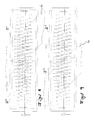
- FIG. 1 shows a turning bar 1 which deflects the printing material web to the right.
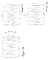
- an adjusting mechanism is arranged, which serves for rotational and axial adjustment of the inner tube 3 relative to the outer tube 19.
- a turning of the turning bar for production in the opposite direction of web travel is possible.
- a first part 15 of the holder 18 is released from a second part 17 by corresponding fastening screws that connect the support members 15, 17 are released.
- the first part 15 of the holder 18 and the second part 17 of the holder 18 are still connected to each other via an axis 16 after separation of the support members.
- FIG. 3 shows the turner bar in a position for production with a paper web 6 deflected to the left.
- FIG. 4 shows the development of an outer tube 19 and an underlying development of the inner tube 3.
- holes 2 are formed, each associated with a slot 4 in the inner tube.
- all air passage openings 2, 4 are open for a selected web running direction.
- the two tubes are in the position "R0" 5, which is displayed on the turning bar by means of a corresponding scale.
- Reference numeral 7 shows the ab toen width ranges of the turning bar, which can be opened or closed for adjustment to a corresponding paper web 6.
- FIG. 5 shows a representation corresponding to FIG. 4 with the web running direction to the left, ie here the position "L0" 8 of the turning bar is set, so that the air passage openings are closed corresponding to the side edges of the paper web 6.
- FIGS. 6 and 7 show by way of example the settings "R3" 9 and "L3" 10 for a relatively narrow printing material web.
- FIG. 8 shows a further embodiment of the invention, in which two inner tubes 3 'and 3 "are provided.
- the use of two inner tubes serves to close the air passage openings 2, 4 of one half of the turning bar, so that with one half By an axially displaced inner tube 3 'or 3 ", all holes 2 of the outer tube 19 are closed regardless of the radial position of the inner tube.
- Figures 10 to 12 show an embodiment with only one inner tube, wherein the slots 4 are formed wider than the diameter of a bore 2.
- the assignment of the holes to the slots when fully open state is such that the bore towards the center of the turning bar each on the inner side of the slot. This makes it possible to close in each case one half of the turning bar by the axial displacement indicated by arrows in Figures 11 and 12, so that can be produced with half the paper web.
- FIG. 13 shows the adjusting mechanism for the axial and radial displacement of the inner tubes 3 ', 3 "relative to the outer tube 19.
- the radial adjustment takes place via a rotary knob 11, which is connected to a spindle 12 for rotationally driving the two inner tubes 3', 3" is.
- the knob 11 has a position indicator (not shown).
- latching elements 13 for fixing the position of the inner tubes 3 ', 3 "in the radial and axial direction are shown axial adjustment of the inner tubes 3 ', 3 "via an axially displaceable actuator 14 with a corresponding positional fixation.
Landscapes
- Engineering & Computer Science (AREA)
- Mechanical Engineering (AREA)
- Registering, Tensioning, Guiding Webs, And Rollers Therefor (AREA)
- Rotary Presses (AREA)
Applications Claiming Priority (1)
| Application Number | Priority Date | Filing Date | Title |
|---|---|---|---|
| DE102006013659A DE102006013659A1 (de) | 2006-03-24 | 2006-03-24 | Wendestange für Rotationsdruckmaschinen |
Publications (2)
| Publication Number | Publication Date |
|---|---|
| EP1837177A2 true EP1837177A2 (fr) | 2007-09-26 |
| EP1837177A3 EP1837177A3 (fr) | 2010-10-27 |
Family
ID=38230041
Family Applications (1)
| Application Number | Title | Priority Date | Filing Date |
|---|---|---|---|
| EP07005867A Withdrawn EP1837177A3 (fr) | 2006-03-24 | 2007-03-22 | Barre de retournement pour presse rotative |
Country Status (4)
| Country | Link |
|---|---|
| US (1) | US7654428B2 (fr) |
| EP (1) | EP1837177A3 (fr) |
| CN (1) | CN101041284B (fr) |
| DE (1) | DE102006013659A1 (fr) |
Cited By (1)
| Publication number | Priority date | Publication date | Assignee | Title |
|---|---|---|---|---|
| EP2336061A1 (fr) | 2009-12-17 | 2011-06-22 | WIFAG Maschinenfabrik AG | Dispositif de basculement à barre de retournement |
Families Citing this family (7)
| Publication number | Priority date | Publication date | Assignee | Title |
|---|---|---|---|---|
| CN102177023A (zh) * | 2008-10-10 | 2011-09-07 | 惠普开发有限公司 | 自动清理空气惰轮 |
| JP2010227545A (ja) * | 2009-03-02 | 2010-10-14 | Uni Charm Corp | 折り装置及び吸収性物品の製造方法 |
| EP2455316A4 (fr) * | 2009-07-15 | 2012-12-19 | Toyo Kohan Co Ltd | Dispositif de flottement et de transport de bande et son procédé de fabrication |
| WO2011139919A1 (fr) * | 2010-05-06 | 2011-11-10 | Clear Lam Packaging, Inc. | Système et procédé synergétique d'extrusion de feuille de biopolymère soufflée |
| WO2013022663A1 (fr) * | 2011-08-05 | 2013-02-14 | North Cutting Systems, Llc | Surface de redirection à actionnement pneumatique |
| US20130256362A1 (en) * | 2012-03-30 | 2013-10-03 | Michael T. Dobbertin | Replaceable cover for bars in a printing system |
| JP6444929B2 (ja) * | 2016-04-15 | 2018-12-26 | ファナック株式会社 | 巻線を圧接結線して構成される配線基板を備える電動機 |
Citations (3)
| Publication number | Priority date | Publication date | Assignee | Title |
|---|---|---|---|---|
| JPS508927U (fr) * | 1973-05-23 | 1975-01-29 | ||
| JPH0648629A (ja) * | 1992-07-24 | 1994-02-22 | Mitsubishi Heavy Ind Ltd | 輪転印刷機におけるターンバー |
| US6427941B1 (en) * | 1999-10-08 | 2002-08-06 | Fuji Photo Film Co., Ltd. | Web transporting method and apparatus |
Family Cites Families (17)
| Publication number | Priority date | Publication date | Assignee | Title |
|---|---|---|---|---|
| GB621170A (en) * | 1946-10-31 | 1949-04-05 | Kenneth Warner Jones | Improvements in pneumatic bars for controlling the movement of paper in printing andlike machines |
| DE2920701C2 (de) * | 1979-05-22 | 1983-05-19 | M.A.N. Maschinenfabrik Augsburg-Nürnberg AG, 8900 Augsburg | Halterung für eine Wendestange in einer Druckmaschine |
| DE3215472C2 (de) * | 1982-04-24 | 1984-02-23 | M.A.N.- Roland Druckmaschinen AG, 6050 Offenbach | Luftumspülte Wendestange |
| DE3436870C1 (de) * | 1984-10-08 | 1986-05-15 | U.E. Sebald Druck und Verlag GmbH, 8500 Nürnberg | Luftumspülte Wendestange für Rotationsdruckmaschinen |
| DE4013229C1 (fr) * | 1990-04-26 | 1991-11-07 | Man Roland Druckmaschinen Ag, 6050 Offenbach, De | |
| AU7877491A (en) * | 1990-05-11 | 1991-12-10 | Rudolph J. Liedtke | Air bearing for web material |
| US5233919A (en) * | 1992-06-18 | 1993-08-10 | Heidelberg Harris Gmbh | Angle bar air regulating device for turning a web |
| US5316199A (en) * | 1992-09-18 | 1994-05-31 | Rockwell International Corporation | Adjustable angle bar assembly for a printing press |
| DE4311438C2 (de) * | 1993-04-07 | 1997-06-19 | Koenig & Bauer Albert Ag | Wendestange für eine Materialbahn |
| JP2801519B2 (ja) * | 1993-04-08 | 1998-09-21 | ゴス グラフイック システムズ インコーポレイテッド | 印刷機用の幅調整可能なアングルバー組立体 |
| DE10057886A1 (de) * | 2000-11-22 | 2002-05-23 | Heidelberger Druckmasch Ag | Wendestangenanordnung für bahnverarbeitende Rotationsdruckmaschinen |
| DE10112415A1 (de) * | 2001-03-15 | 2002-10-02 | Koenig & Bauer Ag | Wendestange |
| DE10131272B4 (de) * | 2001-06-28 | 2006-03-30 | Koenig & Bauer Ag | Wendevorrichtung |
| DE10137725C2 (de) * | 2001-08-01 | 2003-09-18 | Koenig & Bauer Ag | Umlenkstange |
| US6796524B2 (en) * | 2002-11-14 | 2004-09-28 | Heidelberger Druckmaschinen Ag | Reversible angle bar for a web printing press |
| DE10307992B4 (de) * | 2003-02-25 | 2005-08-25 | Maschinenfabrik Wifag | Vorrichtung zum Umlenken einer Bahn und ein Verfahren zum Einrichten dieser Vorrichtung |
| US7311234B2 (en) * | 2005-06-06 | 2007-12-25 | The Procter & Gamble Company | Vectored air web handling apparatus |
-
2006
- 2006-03-24 DE DE102006013659A patent/DE102006013659A1/de not_active Withdrawn
-
2007
- 2007-03-22 EP EP07005867A patent/EP1837177A3/fr not_active Withdrawn
- 2007-03-23 CN CN2007100866269A patent/CN101041284B/zh not_active Expired - Fee Related
- 2007-03-23 US US11/728,087 patent/US7654428B2/en not_active Expired - Fee Related
Patent Citations (3)
| Publication number | Priority date | Publication date | Assignee | Title |
|---|---|---|---|---|
| JPS508927U (fr) * | 1973-05-23 | 1975-01-29 | ||
| JPH0648629A (ja) * | 1992-07-24 | 1994-02-22 | Mitsubishi Heavy Ind Ltd | 輪転印刷機におけるターンバー |
| US6427941B1 (en) * | 1999-10-08 | 2002-08-06 | Fuji Photo Film Co., Ltd. | Web transporting method and apparatus |
Cited By (1)
| Publication number | Priority date | Publication date | Assignee | Title |
|---|---|---|---|---|
| EP2336061A1 (fr) | 2009-12-17 | 2011-06-22 | WIFAG Maschinenfabrik AG | Dispositif de basculement à barre de retournement |
Also Published As
| Publication number | Publication date |
|---|---|
| DE102006013659A1 (de) | 2007-09-27 |
| EP1837177A3 (fr) | 2010-10-27 |
| US20070267535A1 (en) | 2007-11-22 |
| CN101041284B (zh) | 2010-12-15 |
| US7654428B2 (en) | 2010-02-02 |
| CN101041284A (zh) | 2007-09-26 |
Similar Documents
| Publication | Publication Date | Title |
|---|---|---|
| EP1837177A2 (fr) | Barre de retournement pour presse rotative | |
| DE69028874T2 (de) | Vorrichtung zum Farbdrucken auf beide Seiten von Druckpapier | |
| DE19614397C2 (de) | Antrieb mit Registervorrichtung für eine Druckeinheit einer Rollenrotationsdruckmaschine | |
| EP0531648B1 (fr) | Machine à couper et à plier une bande de papier imprimée | |
| DE4311438A1 (de) | Wendestange für eine Materialbahn | |
| EP3124657B1 (fr) | Support d'une feuille flexible dans une carde a chapeaux mobiles | |
| EP1415944B1 (fr) | Appareil pour l'ajustement de rouleaux de pression et/ou de lames de coupe dans une plieuse | |
| DE4444062C2 (de) | Vorrichtung zum Ausrichten einer Druckplatte auf einem Plattenzylinder einer Rotationsdruckmaschine | |
| EP1515848B1 (fr) | Paire de cylindres et cylindre d'un groupe d'impression d'une presse rotative offset | |
| DE4117094C2 (de) | Druckluftgespeiste Wendestange zur Umlenkung von Warenbahnen in Rotationsdruckmaschinen | |
| EP2762246B1 (fr) | Dresseuse de fil | |
| DE2920684C2 (de) | Halterung und Antriebsvorrichtung für Wendestangen in Druckmaschinen | |
| EP2241441A1 (fr) | Dispositif de traitement d'un matériau en bande entre deux cylindres de travail pouvant être entraînés de manière opposée | |
| WO2002064473A1 (fr) | Cylindre a lames de pliage d'une machine de pliage et procede de reglage d'une lame de pliage | |
| EP0722831A2 (fr) | Procédé et arrangement pour un moteur électrique pour entraîner un corps de rotation, en particulier un cylindre d'imprimerie | |
| DE10202798B4 (de) | Vorrichtung zum Verstellen von bahnführenden Walzen | |
| DE102009060276A1 (de) | Vorrichtung zum Wenden von bahnförmigen Substraten | |
| EP1228867A2 (fr) | Cylindre dans une plieuse rotative | |
| WO2001083215A1 (fr) | Dispositifs permettant de recouvrir un cylindre d'un habillage avec des elements de reperage | |
| DE10211108A1 (de) | Falzapparat mit gruppenweise verstellbaren Falzklappen | |
| EP0553739B1 (fr) | Dispositif pour régler les éléments de guidage de feuilles d'une rotative | |
| DE4242606C2 (de) | Einrichtung zum Verstellen von Bogenniederhaltern | |
| EP1156006B1 (fr) | Dispositif de pliage à tambour avec un cylindre à lame de pliage | |
| DE19954390C1 (de) | Pneumatische Bogenführungseinrichtung in einer Druckmaschine | |
| DE10257374A1 (de) | Vorrichtung zur Korrektur der lateralen Postition einer Bedruckstoffbahn in einer Rollenrotationsdruckmaschine |
Legal Events
| Date | Code | Title | Description |
|---|---|---|---|
| PUAI | Public reference made under article 153(3) epc to a published international application that has entered the european phase |
Free format text: ORIGINAL CODE: 0009012 |
|
| AK | Designated contracting states |
Kind code of ref document: A2 Designated state(s): AT BE BG CH CY CZ DE DK EE ES FI FR GB GR HU IE IS IT LI LT LU LV MC MT NL PL PT RO SE SI SK TR |
|
| AX | Request for extension of the european patent |
Extension state: AL BA HR MK YU |
|
| RAP1 | Party data changed (applicant data changed or rights of an application transferred) |
Owner name: MANROLAND AG |
|
| PUAL | Search report despatched |
Free format text: ORIGINAL CODE: 0009013 |
|
| AK | Designated contracting states |
Kind code of ref document: A3 Designated state(s): AT BE BG CH CY CZ DE DK EE ES FI FR GB GR HU IE IS IT LI LT LU LV MC MT NL PL PT RO SE SI SK TR |
|
| AX | Request for extension of the european patent |
Extension state: AL BA HR MK RS |
|
| 17P | Request for examination filed |
Effective date: 20110419 |
|
| 17Q | First examination report despatched |
Effective date: 20110606 |
|
| AKX | Designation fees paid |
Designated state(s): CH DE FR GB LI |
|
| 19U | Interruption of proceedings before grant |
Effective date: 20120201 |
|
| 19W | Proceedings resumed before grant after interruption of proceedings |
Effective date: 20140203 |
|
| STAA | Information on the status of an ep patent application or granted ep patent |
Free format text: STATUS: THE APPLICATION HAS BEEN WITHDRAWN |
|
| 18W | Application withdrawn |
Effective date: 20140311 |