EP1836962B1 - Polstereinrichtung für Kompressionsflächen - Google Patents
Polstereinrichtung für Kompressionsflächen Download PDFInfo
- Publication number
- EP1836962B1 EP1836962B1 EP07110110A EP07110110A EP1836962B1 EP 1836962 B1 EP1836962 B1 EP 1836962B1 EP 07110110 A EP07110110 A EP 07110110A EP 07110110 A EP07110110 A EP 07110110A EP 1836962 B1 EP1836962 B1 EP 1836962B1
- Authority
- EP
- European Patent Office
- Prior art keywords
- pad
- compression
- markings
- radiolucent
- ray
- Prior art date
- Legal status (The legal status is an assumption and is not a legal conclusion. Google has not performed a legal analysis and makes no representation as to the accuracy of the status listed.)
- Expired - Lifetime
Links
- 230000006835 compression Effects 0.000 title claims abstract description 67
- 238000007906 compression Methods 0.000 title claims abstract description 67
- 238000009607 mammography Methods 0.000 claims abstract description 20
- 239000004820 Pressure-sensitive adhesive Substances 0.000 claims abstract description 5
- 239000000853 adhesive Substances 0.000 claims description 34
- 230000001070 adhesive effect Effects 0.000 claims description 34
- 239000000463 material Substances 0.000 claims description 19
- 238000001574 biopsy Methods 0.000 claims description 7
- 239000004698 Polyethylene Substances 0.000 claims description 6
- -1 polyethylene Polymers 0.000 claims description 6
- 229920000573 polyethylene Polymers 0.000 claims description 6
- 229920000728 polyester Polymers 0.000 claims description 3
- 239000012858 resilient material Substances 0.000 claims description 2
- 239000003522 acrylic cement Substances 0.000 claims 1
- 239000011810 insulating material Substances 0.000 claims 1
- 239000010410 layer Substances 0.000 description 27
- 238000000034 method Methods 0.000 description 11
- 210000000481 breast Anatomy 0.000 description 10
- 239000006260 foam Substances 0.000 description 4
- 210000005069 ears Anatomy 0.000 description 3
- 206010028980 Neoplasm Diseases 0.000 description 2
- 238000003384 imaging method Methods 0.000 description 2
- 238000003780 insertion Methods 0.000 description 2
- 230000037431 insertion Effects 0.000 description 2
- 230000003902 lesion Effects 0.000 description 2
- 238000000465 moulding Methods 0.000 description 2
- 229920002635 polyurethane Polymers 0.000 description 2
- 239000004814 polyurethane Substances 0.000 description 2
- 208000004434 Calcinosis Diseases 0.000 description 1
- 230000005856 abnormality Effects 0.000 description 1
- NIXOWILDQLNWCW-UHFFFAOYSA-N acrylic acid group Chemical group C(C=C)(=O)O NIXOWILDQLNWCW-UHFFFAOYSA-N 0.000 description 1
- 229920000800 acrylic rubber Polymers 0.000 description 1
- 239000012790 adhesive layer Substances 0.000 description 1
- 210000003484 anatomy Anatomy 0.000 description 1
- 230000002308 calcification Effects 0.000 description 1
- 230000001419 dependent effect Effects 0.000 description 1
- 229920001971 elastomer Polymers 0.000 description 1
- 239000000806 elastomer Substances 0.000 description 1
- 239000012530 fluid Substances 0.000 description 1
- 238000005187 foaming Methods 0.000 description 1
- 230000013011 mating Effects 0.000 description 1
- 238000012986 modification Methods 0.000 description 1
- 230000004048 modification Effects 0.000 description 1
- 238000007649 pad printing Methods 0.000 description 1
- 229920000058 polyacrylate Polymers 0.000 description 1
- 229920006267 polyester film Polymers 0.000 description 1
- 229920000098 polyolefin Polymers 0.000 description 1
- 230000005855 radiation Effects 0.000 description 1
- 210000004243 sweat Anatomy 0.000 description 1
- 229920003051 synthetic elastomer Polymers 0.000 description 1
- 239000005061 synthetic rubber Substances 0.000 description 1
- 230000000007 visual effect Effects 0.000 description 1
- 239000002699 waste material Substances 0.000 description 1
- 238000003466 welding Methods 0.000 description 1
Images


Classifications
-
- A—HUMAN NECESSITIES
- A61—MEDICAL OR VETERINARY SCIENCE; HYGIENE
- A61B—DIAGNOSIS; SURGERY; IDENTIFICATION
- A61B6/00—Apparatus or devices for radiation diagnosis; Apparatus or devices for radiation diagnosis combined with radiation therapy equipment
- A61B6/50—Apparatus or devices for radiation diagnosis; Apparatus or devices for radiation diagnosis combined with radiation therapy equipment specially adapted for specific body parts; specially adapted for specific clinical applications
- A61B6/502—Apparatus or devices for radiation diagnosis; Apparatus or devices for radiation diagnosis combined with radiation therapy equipment specially adapted for specific body parts; specially adapted for specific clinical applications for diagnosis of breast, i.e. mammography
-
- A—HUMAN NECESSITIES
- A61—MEDICAL OR VETERINARY SCIENCE; HYGIENE
- A61B—DIAGNOSIS; SURGERY; IDENTIFICATION
- A61B6/00—Apparatus or devices for radiation diagnosis; Apparatus or devices for radiation diagnosis combined with radiation therapy equipment
- A61B6/04—Positioning of patients; Tiltable beds or the like
- A61B6/0407—Supports, e.g. tables or beds, for the body or parts of the body
- A61B6/0414—Supports, e.g. tables or beds, for the body or parts of the body with compression means
Definitions
- the present invention relates generally to a device and an apparatus for cushioning surfaces, and more particularly to a device and an apparatus for cushioning or padding surfaces of compression plates applied to body parts during x-ray procedures, for example, during mammography, biopsies, and the like.
- a patient's breast is placed under compression by opposing plates attached to a mammography unit.
- an x-ray may be taken to determine the presence or absence of suspect lesions in the breast tissue, e.g., calcifications or tumors.
- An important reason for compressing the breast during mammography is to provide a thinner cross-section of tissue for the x-rays to pass through.
- the breast When the breast is compressed, it may provide optimal imaging of tissue abnormalities and/or may allow lower doses of x-ray radiation to be used, thereby reducing x-ray radiation exposure to the patient.
- FIGS. 1 , 2A, and 2B show a mammography unit 10, including a base 12 and a rotating assembly 14 that includes an x-ray source 16, a compression paddle 18, and an x-ray plate 20.
- the x-ray plate 20, often referred to as a "bucky,” is stationary relative to the rotating assembly 14, while the compression paddle 18 may be attached to an interchange assembly 22 that is movable relative to the x-ray plate 20.
- the x-ray plate 20 generally includes two patient contact surfaces, a primary tissue contact surface 24 and a front surface 26, as well as side surfaces 28. At least one of the side surfaces 28 may include an opening 30 into which an x-ray cassette 32 may be inserted:
- FIGS. 4A and 4B show attachments that may be placed on the x-ray plate 20 to enhance imaging, e.g., an attachment 40 for spot compression and an attachment 42 for magnification.
- the compression paddle 18 also generally includes two patient contact surfaces, a primary tissue contact surface 34 and a front surface 36, as well as two side surfaces 38.
- FIGS. 3A-3C show other configurations of compression paddles 44-48 that may have various shapes and sizes depending upon a patient's anatomy and/or the type of x-ray view that is desired.
- the patient's breast With the patient (not shown) leaning against the front surfaces 26, 36, the patient's breast (also not shown) is placed on the primary contact surface 24 of the x-ray plate 20 and the compression paddle 18 is moved towards the x-ray plate 20 to compress the breast between the primary contact surfaces 24, 34.
- a series of x-rays may be taken of the breast tissue, e.g., involving moving the rotating assembly 14 and/or repositioning the patient's breast after each film exposure.
- One of the problems with mammography is that the patient may experience significant discomfort during compression of the breast. Because of this, some women may avoid having a mammogram taken, rather than experience the pain that may be caused during the procedure. Although patients may tolerate the pain caused by compression up to about ten to eleven (10-11) compression units, clinical mammography may involve up to sixteen to eighteen (16-18) compression units. If greater compression is used, the quality of the mammogram may be enhanced, thereby increasing the physician's ability to detect cancers or suspect lesions. However, with greater compression comes increased discomfort.
- U.S. Patent No. 5,541,972 discloses a padding device that may be added to cover the front surface of an x-ray plate. Because the padding device is made from materials that may be radiopaque, the padding device is generally positioned to avoid disposing it within the field of the x-ray plate.
- U.S. Patent No. 5,185,776 discloses a radiolucent pad that is glued to a sleeve.
- An x-ray cassette may be inserted into the sleeve, a patient may be disposed against the pad, and an x-ray image obtained.
- the sleeve and pad are disposed of after the x-ray procedure. Disposing of the entire x-ray sleeve after a single use, however, may increase the cost of x-ray procedures.
- EP 0 682 913 A discloses a device for attachment to a compression surface of a mammography unit, comprising a paddle shield cover comprising radiolucent material, the paddle shield cover comprising first and second surfaces, and means for attaching the first surface of the paddle shield cover to the compression surface.
- the present invention is directed to a device and an apparaturs for cushioning surfaces, for example, for cushioning or padding surfaces of compression devices applied to body parts during x-ray procedures, such as during mammography, biopsies, and the like.
- the present invention provides a device for attachment to a compression surface of a mammography unit and an apparatus for compressing a tissue structure having the technical features according to the independent claims. Preferred embodiments of the present invention are described in the dependent claims.
- a device for attachment to a compression device of a mammography unit or a stereotactic biopsy unit.
- the device generally includes a pad formed at least partially from radiolucent material.
- the pad includes first and second surfaces, and markings for orienting a tissue structure applied against the second surface.
- the markings may include notches or indents in at least one of the first and second surfaces and/or in one or more edges of the pad.
- the markings may be radiolucent (i.e., detectable visually, but undetectable by x-ray).
- the markings may be radiopaque, e.g., printed on at least one of the first and second surfaces.
- the device may include a layer of adhesive for removably attaching the first surface of the pad to the compression device.
- a radiolucent adhesive may be applied directly to the first surface, such as a pressure sensitive adhesive.
- the first surface may include a texture, e.g., an inherent texture of the first surface or a texture applied to the first surface, to provide sufficient friction between the first surface and an object.
- the layer of adhesive includes a double coated tape attached to the first surface, as described above.
- Polyethylene tape may be preferred because of its elasticity, which may facilitate securing the device around corners of a compression device while minimizing creation of air pockets or creases that may be visible on an x-ray image.
- the device may be attached to a compression device and/or may include other features, e.g., similar to the embodiments described above.
- FIGS. 5 and 6 show a cross-section of a preferred embodiment of a pad 110, in accordance with the present invention.
- the pad 110 includes a padding layer 112 of compressible and/or resilient material defining first and second surfaces 114, 116, and a layer of adhesive 118 attached to the first surface 114.
- the padding layer 112 may be constructed from one or more materials in a configuration that produces no significant visual artifacts on a mammogram (i.e., are radiolucent), and/or that are resiliently deformable under forces applied during compression to provide comfort.
- a compression device e.g., an x-ray plate or a compression paddle, such as those shown in FIGS. 2A-4C
- This conformability may minimize the risk of air pockets and/or folds that may be visible on an x-ray image.
- the padding layer 112 is formed from a single sheet of elastomer or gel, e.g., an open cell foam, such as polyolefin or polyurethane. More preferably, the padding layer 112 is a sheet of polyurethane open cell foam, such as a 2.3-2.7 kg (5-61b) density foam, that has excellent radiolucent characteristics and a substantially soft tactile feel. In exemplary embodiments, the padding layer 112 may have a thickness of between about 1.27 millimeters (0.050 inch) and 12.7 millimeters (0.500 inch), and preferably between about 5.08 millimeters (0.200 inch) and 6.35 millimeters (0.250 inch).
- the padding layer may include one or more regions that are substantially radiolucent and one or more additional regions that are not radiolucent and/or are radiopaque.
- the exemplary pad 710' shown in FIG. 12A includes a central radiolucent window 721' and a perimeter 720' that is radiopaque.
- the layer of adhesive 118 is preferably a double coated tape 120 that includes first and second surfaces 122, 124 coated with adhesives 126, 128.
- the tape 120 may include a polyester or polyethylene film. Polyethylene may be more elastic, i.e., flexible and/or stretchable than polyester, and therefore may be preferred if the pad 110 is being stretched and/or bent along surfaces, as described further below.
- the tape 120 may have a thickness of between about 25.4 and 254 ⁇ m (1-10 mils), and preferably not more than about 76.2 ⁇ m (3 mils).
- the adhesives 126, 128 are pressure sensitive, such as an acrylic or synthetic rubber adhesive.
- the adhesive 126 on the first surface 122 may substantially permanently attach the tape 120 to the padding layer 112.
- the adhesive 128 on the second surface 124 may have sufficient tackiness to securely, but detachably, attach the pad 110 to a surface, e.g., of a compression device or tissue (not shown).
- the adhesive 128 allows easy removal of the pad 110 from the surface, e.g., leaving substantially no residue of adhesive on the surface.
- the adhesive 126 on the first surface 122 may have a thickness of between about 25.4 and 127 ⁇ m (1-5 mils), and preferably not more than about 31.75 ⁇ m (1.25 mils).
- the adhesive 128 on the second surface 124 may have a thickness of between about 25.4 and 127 ⁇ m (1-5 mils), and preferably not more than about 31.75 ⁇ m (1.25 mils).
- a pressure sensitive adhesive (not shown) may be applied directly to the first surface 114 of the padding layer 112.
- a non-adhesive gel may be applied to the first surface 114 and/or to the compression surface (not shown) that provides a sufficient coefficient of friction between the pad 110 and the compression surface to secure the pad 110 in place.
- the first surface 114 of the padding layer 112 may include a texture (not shown) such that the first surface is sufficiently tacky to allow removable attachment of the pad to a surface, e.g., by friction with or without the need for an adhesive.
- the inherent texture of the foam defining the padding layer 112 may be sufficiently skid-free for use on a top surface of a device, such as an x-ray plate.
- additional texturing may be created in the first surface 114 to enhance frictional engagement with a contact surface.
- a material (not shown) may be applied to the first surface 114 to provide a desired texture.
- the layer of adhesive 118 may cover the entire first surface 114, and therefore the layer of adhesive 118 should be radiolucent.
- the layer of adhesive 118 may cover one or more particular regions of the first surface 114, e.g., along the outer border (not shown).
- the layer of adhesive 118 may be radiopaque in one or more regions that are outside the field of an x-ray plate and radiolucent if inside the field of the x-ray plate.
- a peel-away cover sheet 130 may be provided over the layer of adhesive 118.
- a peel-away packet (not shown) may be provided within which the pad 110 may be stored before use.
- a first preferred embodiment of a pad 210 is shown, having a generally "T" shape, including a central region 220 and a pair of wings 222 extending from opposing side edges 224 of the pad 220.
- the wings 222 extend along a front edge 226 of the pad, thereby defining a front region 228 between the wings 222.
- the pad 210 may be attached to primary contact, front, and side surfaces 34, 36, 38 of a compression paddle 18.
- the pad 210 may be placed with the second surface facing downward or away from the compression paddle 18.
- a cover sheet (if provided) may be removed from the layer of adhesive (not shown), and the central region 220 may be aligned with the primary contact surface 34 such that the front region 228 may be bent and applied to the front surface 36 of the compression paddle 18.
- the wings 222 may then be bent and applied along the side surfaces 38.
- the pad 210 may provide cushioning along the front and side surfaces 36, 38, as well as the primary contact surface 34, which may increase a patient's comfort, particularly if the patient's body is pressed against the front and side surfaces 36, 38, and/or the corners between them.
- FIG. 7B an alternative embodiment of a pad 310 is shown that includes a central region 320, side regions 322 including ears 330, and a front region 328. Similar to the previous embodiment, the central region 320 may be aligned and applied to a primary contact surface 34 of a compression paddle 18 (not shown in FIG. 7B ) such that the front region 328 may be bent and applied against the front surface 36. The side regions 322 may be bent and applied against the side surfaces 38, and then the ears 330 may be bent to cover the balance of the front surface 36.
- One advantage of this embodiment is that it may minimize waste of pad material as compared with cutting or otherwise forming the "T" shaped pad 220 of FIG. 7A .
- a pad 410 may be provided that includes front and side regions 428, 422 extending from a central region 420.
- the front and side regions 428, 422 may be applied against front and side surfaces 36, 38 of a compression paddle 18 when the central region 420 is applied against a primary contact surface 34.
- a polyethylene double coated tape (not shown) in the layer of adhesive.
- a polyethylene film may stretch and/or otherwise conform better when bent around corners of the compression paddle than a polyester film.
- a similar pad 210 may be applied to an x-ray plate 20, such as that shown in FIG. 2A .
- a central region 220 of the pad 210 is applied to a primary contact surface 24, a front region 228 may be applied to a front surface 26, and wings 222 (or other side regions, not shown) may cover side surfaces 28.
- wings 222 or other side regions, not shown
- the wing(s) 222 may include a reusable adhesive (not shown) that may allow attachment of the wing(s) 222 to the side surface(s) 28, but allow removal without disturbing the rest of the pad 222 to allow insertion of the x-ray cassette 32. The wing 222 may then be reapplied to the side surface 28, thereby providing cushioning along the side surface 28 further during the procedure.
- FIG. 9 another embodiment of a pad 510 is shown that may be used to provide cushioning along the x-ray plate 20 (not shown in FIG. 9 , see FIG. 2A ) while providing access to an opening 30 in a side surface 28 of the x-ray plate 20.
- the pad 510 generally includes a central region 520, a front region 528, and side regions 522 including ears 530, similar to the embodiment shown in FIG. 7B .
- one or both side regions 522 may also include a slot 532 therethrough that corresponds substantially to the shape of the opening 30 in the side surface 28 of the x-ray plate 20.
- the slot(s) 532 may allow insertion and/or removal of an x-ray cassette 32 into and/or out of the opening(s) 30 in the x-ray plate 20.
- pad configurations such as those shown in FIGS. 7A or 7C may be used with slots (not shown) provided in the wings 222 or side regions 422.
- different pad segments may be removably and/or permanently attached to an x-ray plate, compression paddle, or other compression device.
- slip-over pads may be provided instead of the generally planar pads described above.
- the slip-over pads may be preformed to include multiple panels that may be removably secured around a compression device, such as the x-ray plate 20, shown in FIG. 2A .
- a five-sided slip-over pad 610 is shown that includes a top panel 620, side panels 622, and a bottom panel 624, defining an opening 628, as well as, optionally, including a back panel 626.
- the slip-over pad 610 may be formed from one or more sheets of material, similar to the pads described above.
- the panels 620, 622, 624, 626 are formed from a single sheet of padding material that are cut and/or folded into a sleeve shape. Any seams (not shown) may be connected by beveling, lapping, and/or butting mating edges or surfaces of the sheet, and bonding them, e.g., using an adhesive, sonic welding, and the like.
- the padding material is radiolucent.
- one or more regions of one or more panels may be radiolucent, while the remainder of the padding material need not be, similar to the pad shown in FIG. 12A .
- Any adhesive and the like that is used may also be radiolucent, e.g., if it will be exposed within the field of the x-ray plate 20.
- An inside surface of the slip-over pad 610 may be substantially smooth and free of adhesive to allow the x-ray plate 20 to be slidably received in the opening 628, e.g., until the x-ray plate 20 abuts the back panel 626.
- the slip-over pad 610 may be sized to fit around the x-ray plate 20 without sliding substantially during a mammography procedure, e.g., due to friction between the padding material and the x-ray plate surfaces.
- one or more inside surfaces of the slip-over pad 610 may include a texture to enhance the frictional engagement with the x-ray plate 20 and/or an adhesive may be applied, similar to the embodiments described above, that allow the clip cover pad 610 to be secured yet slidably removable from the x-ray plate 20.
- a slip-over pad 610' may include one or more slots 632 corresponding to opening(s) in the x-ray plate 20 (not shown, see FIG. 2A ), similar to the embodiments described above.
- a slip-over pad 610" may be provided that does not include a bottom panel.
- the top and side panels 620", 622" (and the back panel, not shown, if included) may be sufficiently rigid relative to one another in order to fit snugly around the x-ray plate 20, either with or without using an adhesive, textured surfaces, or other altered surfaces.
- a wrap-around pad 710 is shown that generally includes a central region 720 and a pair of side regions 722.
- the central region 720 may be aligned with a primary contact surface 709 of a compression device 708, such as an x-ray plate, while the side regions 722 extend around the compression device 708 to substantially secure the pad 710 relative to the compression device 708.
- the pad 710 may be constructed similarly to the pads described above, i.e., including a padding layer.
- a pad 710 may be formed from radiolucent material.
- the side regions 722 may wrap entirely around the compression device 708 until they overlap one another.
- the side regions 722 may include cooperating connectors, e.g., one or more layers of adhesive, hook and loop connectors, and the like, that may secure the side regions 722 together.
- a layer of adhesive (not shown) may be provided along all or a portion of the surface of the pad 710 contacting the compression device 708.
- the side regions 722 may be sufficiently long to extend around to a lower surface of the compression device 708 without overlapping one another, but may include a layer of adhesive, a textured surface, and/or other altered surface to attach to the lower surface of the compression device 708.
- the side regions 722 are shown as being symmetrical, it will be appreciated that one may be longer than the other, e.g., if desired to move the overlap region out of the field of the x-ray plate.
- FIG. 12B another pad 710' is shown that includes a radiolucent region 721' in the central region 720', while the remainder of the central region 720' is not necessarily radiolucent (e.g., radiopaque).
- the side panels 722' are shown as being radiopaque, although some regions may also be radiolucent, e.g., any regions that extend into the field of the x-ray plate.
- a pad 710 which may be entirely or only partially radiolucent, may include a front region 728" that may be bent and applied to a front surface of a compression device (not shown).
- FIG. 12D another pad 710''' is shown that includes a front region 728'" that is sufficiently long to extend to a lower surface of the compression device, whereupon the side regions 722'" may overlap and/or be secured to the front region 720"' along the lower surface.
- any of these embodiments may include one or more slots corresponding to an opening in an x-ray plate (not shown), similar to the embodiments described above.
- FIGS. 13A and 13B another embodiment of a pad 810 is shown that includes a central region 820 including radiolucent padding material, similar to the previous embodiments.
- the pad 810 may include slots, side regions, front regions, and/or may be formed into a slip-over and/or wrap-around pad (not shown), as described above.
- the pad 810 includes markings formed therein, thereby providing a grid 834, as best seen in FIG. 13A .
- the grid 834 may be formed by cutting notches, molding indents, and the like into one or both upper and lower surfaces of the pad 810, as shown in FIG. 13B .
- notches may be provided in one or more edges (not shown) of the pad 810 to assist in aligning a tissue structure (not shown) on the pad 810.
- the grid 834 may be printed on one or both surfaces or embedded into the padding layer (not shown), e.g., during a foaming, die cutting, or molding process used to create the padding layer, or a pad printing process.
- the grid 834 may be manually printed onto the exposed surface of the pad 810 shortly before performing a mammography procedure. Although a grid 834 is shown, other markings (not shown) may be provided that may assist in orienting a tissue structure applied against the pad 810.
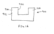
- the pad 910 which may be formed from materials and/or including an adhesive or texturing, similar to the embodiments described above, generally includes a panel 912 defining a window 932 formed therein.
- the panel 912 has a "U" shape defining opposing side regions 934 on either side of the window 932.
- the panel may be rectangular or may include any of the shapes described above, yet having a window cut or otherwise formed in the panel (not shown).
- the pad 910 may be secured to a primary contact surface of a compression device, e.g., on a stereotactic biopsy apparatus, e.g., a vertically mounted compression device (not shown).
- a tissue structure e.g., a patient's breast, may be compressed against the pad 910 such that a target region of the tissue structure is disposed within the window, e.g., to facilitate obtaining a biopsy and the like, as is well known in the art.
Landscapes
- Health & Medical Sciences (AREA)
- Life Sciences & Earth Sciences (AREA)
- Medical Informatics (AREA)
- Engineering & Computer Science (AREA)
- Radiology & Medical Imaging (AREA)
- Molecular Biology (AREA)
- Biophysics (AREA)
- High Energy & Nuclear Physics (AREA)
- Veterinary Medicine (AREA)
- Nuclear Medicine, Radiotherapy & Molecular Imaging (AREA)
- Optics & Photonics (AREA)
- Pathology (AREA)
- Public Health (AREA)
- Biomedical Technology (AREA)
- Heart & Thoracic Surgery (AREA)
- Physics & Mathematics (AREA)
- Surgery (AREA)
- Animal Behavior & Ethology (AREA)
- General Health & Medical Sciences (AREA)
- Dentistry (AREA)
- Oral & Maxillofacial Surgery (AREA)
- Apparatus For Radiation Diagnosis (AREA)
- Soft Magnetic Materials (AREA)
- Casting Or Compression Moulding Of Plastics Or The Like (AREA)
- Surgical Instruments (AREA)
- Magnetic Resonance Imaging Apparatus (AREA)
- Cameras Adapted For Combination With Other Photographic Or Optical Apparatuses (AREA)
Claims (20)
- Eine Vorrichtung zum Anbringen an einer Kompressionsfläche einer Mammographie-Einheit, aufweisend:ein Pad (810), das strahlendurchlässiges Material aufweist, wobei das Pad (810) eine erste und eine zweite Fläche aufweist, wobei das Pad (810) Markierungen (834) zum Ausrichten einer gegen die zweite Fläche angelegten Gewebestruktur aufweist, undMittel zum Anbringen der ersten Fläche des Pads (810) an der Kompressionsfläche.
- Die Vorrichtung gemäß Anspruch 1, wobei die Markierungen (834) Aussparungen oder Vertiefungen in mindestens einer der ersten und der zweiten Fläche aufweisen.
- Die Vorrichtung gemäß Anspruch 1, wobei die Markierungen (834) auf mindestens eine der ersten und der zweiten Fläche aufgedruckte Markierungen aufweisen.
- Die Vorrichtung gemäß Anspruch 1, wobei die Markierungen in einer Padschicht des Pads eingebettet sind.
- Die Vorrichtung gemäß einem der Ansprüche 1 bis 3, wobei die Markierungen (834) eine oder mehr Achsen aufweisen, die entlang der zweiten Fläche definiert sind.
- Die Vorrichtung gemäß einem vorhergehenden Anspruch, wobei das Mittel zum Anbringen ein auf die erste Fläche aufgebrachtes strahlendurchlässiges Haftmittel aufweist.
- Die Vorrichtung gemäß einem der Ansprüche 1 bis 5, wobei das Mittel zum Anbringen eine Textur an der ersten Fläche aufweist.
- Die Vorrichtung gemäß einem der Ansprüche 1 bis 5, wobei das Mittel zum Anbringen ein an der ersten Fläche angebrachtes Band aufweist, wobei das Band eine ein druckempfindliches Haftmittel aufweisende freiliegende Fläche aufweist.
- Die Vorrichtung gemäß Anspruch 8, wobei das druckempfindliche Haftmittel einen Acrylklebstoff aufweist.
- Die Vorrichtung gemäß Anspruch 8 oder 9, wobei das Band mindestens eines von Polyester und Polyethylen aufweist.
- Die Vorrichtung gemäß Anspruch 8 oder 9, wobei das Band ein doppelt beschichtetes Band aufweist.
- Die Vorrichtung gemäß einem vorhergehenden Anspruch, wobei das Pad (810) ein nachgiebiges Material aufweist.
- Die Vorrichtung gemäß einem vorhergehenden Anspruch, wobei das Pad (810) ein wärmeisolierendes Material aufweist.
- Die Vorrichtung gemäß einem vorhergehenden Anspruch, wobei die Markierungen (834) strahlenundurchlässig sind.
- Die Vorrichtung gemäß einem der Ansprüche 1 bis 13, wobei die Markierungen (834) strahlendurchlässig sind.
- Eine Vorrichtung zum Komprimieren einer Gewebestruktur, aufweisend:eine Kompressionsvorrichtung, die eine ein strahlendurchlässiges Material aufweisende primäre Kontaktfläche aufweist, undein Pad (810) gemäß einem vorhergehenden Anspruch, das lösbar an der primären Kontaktfläche befestigt ist.
- Die Vorrichtung gemäß Anspruch 16, wobei die Kompressionsvorrichtung eine oder mehr Seitenflächen aufweist, die sich seitlich von der primären Kontaktfläche aus erstrecken, und wobei das Pad (810) ebenfalls lösbar an der einen oder den mehreren Seitenflächen befestigt ist.
- Die Vorrichtung gemäß Anspruch 16, wobei die Kompressionsvorrichtung eine Öffnung aufweist, um darin ein Röntgerielement aufzunehmen, und wobei das Pad (810) dadurch hindurch einen Schlitz aufweist, der mit der Öffnung korrespondiert.
- Die Vorrichtung gemäß Anspruch 16, wobei die Kompressionsvorrichtung ein Kompressionspaneel einer stereotaktischen Biopsie-Vorrichtung aufweist, und wobei das Pad (810) darin ein Fenster aufweist.
- Die Vorrichtung gemäß Anspruch 19, wobei das Pad (810) ein "U"-förmiges Paneel aufweist, das zwischen einander entgegengesetzten Abschnitten des Paneels ein Fenster definiert.
Applications Claiming Priority (2)
| Application Number | Priority Date | Filing Date | Title |
|---|---|---|---|
| US09/922,602 US6765984B2 (en) | 2000-03-06 | 2001-08-03 | Device for cushioning of compression surfaces |
| EP02756636A EP1420695B1 (de) | 2001-08-03 | 2002-07-24 | Vorrichtung zur kompression einer gewebestruktur |
Related Parent Applications (2)
| Application Number | Title | Priority Date | Filing Date |
|---|---|---|---|
| EP02756636A Division EP1420695B1 (de) | 2001-08-03 | 2002-07-24 | Vorrichtung zur kompression einer gewebestruktur |
| EP02756636.3 Division | 2002-07-24 |
Publications (3)
| Publication Number | Publication Date |
|---|---|
| EP1836962A2 EP1836962A2 (de) | 2007-09-26 |
| EP1836962A3 EP1836962A3 (de) | 2007-12-12 |
| EP1836962B1 true EP1836962B1 (de) | 2011-03-30 |
Family
ID=25447300
Family Applications (2)
| Application Number | Title | Priority Date | Filing Date |
|---|---|---|---|
| EP02756636A Expired - Lifetime EP1420695B1 (de) | 2001-08-03 | 2002-07-24 | Vorrichtung zur kompression einer gewebestruktur |
| EP07110110A Expired - Lifetime EP1836962B1 (de) | 2001-08-03 | 2002-07-24 | Polstereinrichtung für Kompressionsflächen |
Family Applications Before (1)
| Application Number | Title | Priority Date | Filing Date |
|---|---|---|---|
| EP02756636A Expired - Lifetime EP1420695B1 (de) | 2001-08-03 | 2002-07-24 | Vorrichtung zur kompression einer gewebestruktur |
Country Status (9)
| Country | Link |
|---|---|
| US (1) | US6765984B2 (de) |
| EP (2) | EP1420695B1 (de) |
| JP (1) | JP4373210B2 (de) |
| AT (2) | ATE364351T1 (de) |
| AU (1) | AU2002322630B2 (de) |
| CA (1) | CA2454633C (de) |
| DE (2) | DE60220680T2 (de) |
| NZ (1) | NZ530933A (de) |
| WO (1) | WO2003013358A2 (de) |
Families Citing this family (44)
| Publication number | Priority date | Publication date | Assignee | Title |
|---|---|---|---|---|
| US6577702B1 (en) * | 2000-03-06 | 2003-06-10 | Biolucent, Inc. | Device for cushioning of compression surfaces |
| US6850590B2 (en) * | 2001-11-23 | 2005-02-01 | Benjamin M. Galkin | Mammography cassette holder for patient comfort and methods of use |
| US6975701B2 (en) * | 2001-11-23 | 2005-12-13 | Galkin Benjamin M | Devices for patient comfort in mammography and methods of use |
| US20040206738A1 (en) * | 2001-12-28 | 2004-10-21 | Ge Medical Systems Global Technology Company, Llc | Mammography patient contact temperature controller |
| SE0201806D0 (sv) | 2002-06-13 | 2002-06-13 | Siemens Elema Ab | Röntgendiagnostikapparat för mammografi undersökningar |
| FR2853520B1 (fr) * | 2003-04-11 | 2006-01-27 | Ge Med Sys Global Tech Co Llc | Pelote de compression et appareil de radiographie |
| US20040218727A1 (en) * | 2003-05-01 | 2004-11-04 | S&S X-Ray Products, Inc. | Mammography compression cushion system |
| US7142631B2 (en) * | 2003-12-30 | 2006-11-28 | Galkin Benjamin M | Mammography cushioning devices and methods |
| US8100839B2 (en) * | 2003-12-30 | 2012-01-24 | Galkin Benjamin M | Acoustic monitoring of a breast and sound databases for improved detection of breast cancer |
| US7248668B2 (en) * | 2006-04-11 | 2007-07-24 | Galkin Benjamin M | Mammography compression devices and methods |
| US7512211B2 (en) * | 2003-12-30 | 2009-03-31 | Galkin Benjamin M | Mammography systems and methods, including methods for improving the sensitivity and specificity of the computer-assisted detection (CAD) process |
| DE102004052614B3 (de) * | 2004-10-29 | 2006-01-05 | Siemens Ag | Kompressionsplatte, insbesondere für ein Mammographiegerät |
| EP1816964B1 (de) * | 2004-11-02 | 2016-05-18 | Hologic, Inc. | Pads für die mammographie |
| US8089030B2 (en) * | 2005-01-18 | 2012-01-03 | Marvel Concepts, Llc | Bucky warmer with holder |
| US20080247508A1 (en) * | 2005-01-18 | 2008-10-09 | Ann Harrington | Bucky warmer with holder |
| US7489761B2 (en) * | 2006-03-27 | 2009-02-10 | Hologic, Inc. | Breast compression for digital mammography, tomosynthesis and other modalities |
| JP5171289B2 (ja) * | 2008-01-29 | 2013-03-27 | 富士フイルム株式会社 | X線撮像装置及びx線撮像装置使用方法 |
| JP5042884B2 (ja) * | 2008-02-29 | 2012-10-03 | 富士フイルム株式会社 | 放射線画像情報撮影装置 |
| US7972059B2 (en) * | 2008-06-02 | 2011-07-05 | Sherry Behle | X-ray cassette cover |
| US8545098B2 (en) * | 2008-06-02 | 2013-10-01 | Sherry Behle | X-ray cassette cover |
| US20090307191A1 (en) * | 2008-06-10 | 2009-12-10 | Li Hong C | Techniques to establish trust of a web page to prevent malware redirects from web searches or hyperlinks |
| US8401145B1 (en) | 2008-10-23 | 2013-03-19 | Beekley Corporation | Imaging sheet and related method |
| JP5661315B2 (ja) * | 2010-03-31 | 2015-01-28 | 富士フイルム株式会社 | 圧迫板、及び、x線撮像装置 |
| US20120033786A1 (en) * | 2010-08-04 | 2012-02-09 | Izi Medical Products, Llc | Mammography pad |
| DE102010035921B4 (de) * | 2010-08-31 | 2019-05-02 | Siemens Healthcare Gmbh | Kompressionseinheit |
| JP5864891B2 (ja) * | 2011-04-27 | 2016-02-17 | 富士フイルム株式会社 | 放射線画像撮影装置 |
| DE102011076823B4 (de) * | 2011-05-31 | 2017-03-23 | Siemens Healthcare Gmbh | Kontrastmittelgestütztes Mammografiesystem mit Brustkompression |
| JP2014532178A (ja) * | 2011-09-28 | 2014-12-04 | エムシー10 インコーポレイテッドMc10,Inc. | 表面の特性を検出するための電子機器 |
| JP6157491B2 (ja) * | 2011-11-18 | 2017-07-05 | ホロジック, インコーポレイテッドHologic, Inc. | 造影と患者の快適性とを改善する膨張性ジャケットを備えた圧迫パドルを用いたx線マンモグラフィーおよび/または乳房トモシンセシス |
| US9782135B2 (en) | 2011-11-18 | 2017-10-10 | Hologic, Inc. | X-ray mammography and/or breast tomosynthesis using a compression paddle |
| US11259759B2 (en) | 2011-11-18 | 2022-03-01 | Hologic Inc. | X-ray mammography and/or breast tomosynthesis using a compression paddle |
| EP2988674B1 (de) | 2013-04-26 | 2019-07-17 | Hologic Inc. | Röntgen-mammografie und/oder brusttomosynthese unter verwendung eines kompressionspaddles |
| US9247915B2 (en) | 2014-03-05 | 2016-02-02 | Brady Worldwide, Inc. | Microfiber radiography comfort device |
| CN106473758A (zh) * | 2015-08-24 | 2017-03-08 | 上海联影医疗科技有限公司 | 乳腺成像设备及其控制方法 |
| JP6598721B2 (ja) * | 2016-04-01 | 2019-10-30 | 富士フイルム株式会社 | 音響マッチング部材、音響マッチング部材群、及び医用撮影装置 |
| CN110113997B (zh) * | 2016-11-08 | 2024-01-23 | 豪洛捷公司 | 使用弯曲的压缩元件进行成像 |
| WO2019033029A1 (en) | 2017-08-11 | 2019-02-14 | Hologic, Inc. | BREAST COMPRESSION PLATE WITH ACCESS CORNERS |
| EP4129188A1 (de) | 2017-08-16 | 2023-02-08 | Hologic, Inc. | Verfahren zur kompensation von bewegungsartefakten eines patienten bei der brustbildgebung |
| KR102011382B1 (ko) * | 2017-10-11 | 2019-10-21 | 주식회사 뷰웍스 | 맘모그래피 장치 |
| DE102018201401A1 (de) * | 2018-01-30 | 2019-08-01 | Siemens Healthcare Gmbh | Kompressionseinheit für eine Mammographieeinrichtung, Mammographieeinrichtung und Verfahren zum Einsetzen eines Kompressionselements in die Kompressionseinheit |
| JP6945491B2 (ja) * | 2018-04-27 | 2021-10-06 | 富士フイルム株式会社 | マンモグラフィ装置 |
| US11426132B2 (en) | 2018-05-25 | 2022-08-30 | Hologic, Inc. | Breast compression paddle utilizing foam |
| FR3084580B1 (fr) * | 2018-08-06 | 2020-08-07 | Stephanix | Systeme de radiologie telecommande equipe d'un dispositif de compression |
| KR20220130759A (ko) | 2020-01-24 | 2022-09-27 | 홀로직, 인크. | 수평-변위 가능 발포체 유방 압축 패들 |
Family Cites Families (40)
| Publication number | Priority date | Publication date | Assignee | Title |
|---|---|---|---|---|
| FR1302635A (fr) | 1961-07-21 | 1962-08-31 | Radiologie Cie Gle | Système de compression pour appareil d'examen radiologique |
| DE2335576A1 (de) | 1973-07-13 | 1975-01-30 | Philips Patentverwaltung | Roentgendiagnostikgeraet fuer die mammographie |
| US3963933A (en) | 1975-08-18 | 1976-06-15 | General Electric Company | Mammography fixture |
| DE2753047A1 (de) * | 1977-11-28 | 1979-05-31 | Robert Dr Med Novak | Roentgenuntersuchungsgeraet |
| GB2068700B (en) * | 1980-01-26 | 1984-02-15 | Emi Ltd | Positioning devices for patients |
| US4346298A (en) | 1981-03-02 | 1982-08-24 | Dixit Jagannath K | Automatic air pillow for diagnostic X-ray machine |
| US4433690A (en) | 1981-07-20 | 1984-02-28 | Siemens Ag | Compact ultrasound apparatus for medical examination |
| US4691333A (en) | 1985-12-27 | 1987-09-01 | Gabriele Joseph M | Breast compression and needle localization apparatus |
| US4943986A (en) | 1988-10-27 | 1990-07-24 | Leonard Barbarisi | Mammography compression apparatus for prosthetically augmented breast |
| US4923187A (en) | 1989-03-10 | 1990-05-08 | Avec Scientific Utility Corporation | Radiolucent iliac crest support frame |
| US5044008A (en) | 1989-12-12 | 1991-08-27 | Jackson Reginald B | Dental film cartridge cushion |
| US5226070A (en) | 1990-04-03 | 1993-07-06 | Kabushiki Kaisha Toshiba | Mat with low X-ray absorption for X-ray diagnosis |
| US5189686A (en) | 1990-10-02 | 1993-02-23 | American Mammographics, Inc. | Adjustable mounting base for mammographic spot compression and magnification platform |
| US5081657A (en) | 1990-11-09 | 1992-01-14 | National Imaging Consultants, Inc. | Bucky warmer |
| US5185776A (en) | 1991-08-05 | 1993-02-09 | Townsend Boyd E | Cover for an x-ray cassette |
| US5166968A (en) | 1992-02-05 | 1992-11-24 | Morse Arnold W | Portable x-ray cassette holder |
| US5161273A (en) | 1992-05-01 | 1992-11-10 | The United States Of America As Represented By The Secretary Of The Air Force | Neonatal cradle |
| US5260985A (en) * | 1992-08-14 | 1993-11-09 | Mosby Richard A | Conforming localization/biopsy grid and control apparatus |
| US5311883A (en) | 1992-11-06 | 1994-05-17 | Eleanor Sherman | Sanitary shield for dedicated mammography apparatus |
| FR2697741B1 (fr) | 1992-11-10 | 1995-02-03 | Gen Electric Cgr | Dispositif de compression pour appareil radiologique. |
| JP3221947B2 (ja) * | 1992-12-03 | 2001-10-22 | 株式会社東芝 | 業務指示処理装置 |
| FR2702059B1 (fr) | 1993-02-25 | 1995-09-15 | Berneuil Gerard | Procede d'amelioration de la qualite des cliches radiologiques et dispositif permettant la mise en oeuvre du procede. |
| US5541972A (en) | 1993-04-23 | 1996-07-30 | Anthony; Betty J. | Disposable padding device for a mammography X-ray plate |
| US5377254A (en) | 1993-06-21 | 1994-12-27 | Walling; Michael A. | X-ray cassette casing |
| DE4324508A1 (de) | 1993-07-21 | 1995-01-26 | Alois Schnitzler | Vakuumkissen mit Schaumstoffeinlage |
| US6049583A (en) | 1993-08-10 | 2000-04-11 | Galkin; Benjamin M. | Method and apparatus for measuring compression force in mammography |
| US5474072A (en) | 1993-10-29 | 1995-12-12 | Neovision Corporation | Methods and apparatus for performing sonomammography |
| US6038718A (en) | 1994-08-15 | 2000-03-21 | Midmark Corporation | Surgical table |
| WO1996007353A1 (en) | 1994-09-09 | 1996-03-14 | Air-Shields, Inc. | Infant mattress assembly |
| US5632275A (en) | 1994-09-16 | 1997-05-27 | Scribner-Browne Medical Design Incorporated | Catheter lab table pad and method for using the same |
| US5553111A (en) | 1994-10-26 | 1996-09-03 | The General Hospital Corporation | Apparatus and method for improved tissue imaging |
| US5613254A (en) | 1994-12-02 | 1997-03-25 | Clayman; Ralph V. | Radiolucent table for supporting patients during medical procedures |
| US5719916A (en) | 1995-06-05 | 1998-02-17 | Nelson; Robert S. | Anthropomorphic mammography and lung phantoms |
| US5657367A (en) | 1996-06-26 | 1997-08-12 | Couch; Denver | Lateral decubitus patient positioning device |
| US5891074A (en) | 1996-08-22 | 1999-04-06 | Avitar, Inc. | Pressure wound dressing |
| US5832550A (en) | 1997-08-11 | 1998-11-10 | Biotek | Moldable vacuum cushion |
| DE19921100A1 (de) | 1998-05-05 | 2000-03-02 | Kari Richter | Medizinische Kompressionsvorrichtung |
| DE19926446A1 (de) | 1998-07-20 | 2000-01-27 | Siemens Ag | Vorrichtung zur Ultraschallankopplung eines Ultraschall-Applikators |
| DE19956723A1 (de) * | 1999-11-25 | 2001-06-21 | Siemens Ag | Abstandseinstellvorrichtung für ein medizinisches Diagnosegerät |
| US6577702B1 (en) | 2000-03-06 | 2003-06-10 | Biolucent, Inc. | Device for cushioning of compression surfaces |
-
2001
- 2001-08-03 US US09/922,602 patent/US6765984B2/en not_active Expired - Lifetime
-
2002
- 2002-07-24 EP EP02756636A patent/EP1420695B1/de not_active Expired - Lifetime
- 2002-07-24 EP EP07110110A patent/EP1836962B1/de not_active Expired - Lifetime
- 2002-07-24 NZ NZ530933A patent/NZ530933A/en not_active IP Right Cessation
- 2002-07-24 DE DE60220680T patent/DE60220680T2/de not_active Expired - Lifetime
- 2002-07-24 AU AU2002322630A patent/AU2002322630B2/en not_active Ceased
- 2002-07-24 CA CA2454633A patent/CA2454633C/en not_active Expired - Fee Related
- 2002-07-24 JP JP2003518376A patent/JP4373210B2/ja not_active Expired - Fee Related
- 2002-07-24 DE DE60239642T patent/DE60239642D1/de not_active Expired - Lifetime
- 2002-07-24 WO PCT/US2002/023576 patent/WO2003013358A2/en active IP Right Grant
- 2002-07-24 AT AT02756636T patent/ATE364351T1/de active
- 2002-07-24 AT AT07110110T patent/ATE503422T1/de not_active IP Right Cessation
Also Published As
| Publication number | Publication date |
|---|---|
| NZ530933A (en) | 2005-06-24 |
| EP1836962A3 (de) | 2007-12-12 |
| DE60220680T2 (de) | 2008-03-06 |
| WO2003013358A3 (en) | 2003-12-04 |
| US20030007597A1 (en) | 2003-01-09 |
| EP1420695A2 (de) | 2004-05-26 |
| CA2454633A1 (en) | 2003-02-20 |
| WO2003013358A2 (en) | 2003-02-20 |
| ATE503422T1 (de) | 2011-04-15 |
| DE60239642D1 (de) | 2011-05-12 |
| AU2002322630B2 (en) | 2008-10-02 |
| US6765984B2 (en) | 2004-07-20 |
| JP2005523043A (ja) | 2005-08-04 |
| ATE364351T1 (de) | 2007-07-15 |
| DE60220680D1 (de) | 2007-07-26 |
| CA2454633C (en) | 2011-02-15 |
| EP1836962A2 (de) | 2007-09-26 |
| JP4373210B2 (ja) | 2009-11-25 |
| EP1420695B1 (de) | 2007-06-13 |
Similar Documents
| Publication | Publication Date | Title |
|---|---|---|
| EP1836962B1 (de) | Polstereinrichtung für Kompressionsflächen | |
| AU2002322630A1 (en) | Device for cushioning of compression surfaces in mammograph | |
| US9936925B2 (en) | Device for cushioning of compression surfaces | |
| EP1816964B1 (de) | Pads für die mammographie | |
| AU2001240073A1 (en) | Device for cushioning of compression surfaces in mammograph | |
| AU2008201638B2 (en) | Device for cushioning of compression surfaces in mammograph |
Legal Events
| Date | Code | Title | Description |
|---|---|---|---|
| PUAI | Public reference made under article 153(3) epc to a published international application that has entered the european phase |
Free format text: ORIGINAL CODE: 0009012 |
|
| AC | Divisional application: reference to earlier application |
Ref document number: 1420695 Country of ref document: EP Kind code of ref document: P |
|
| AK | Designated contracting states |
Kind code of ref document: A2 Designated state(s): AT BE BG CH CY CZ DE DK EE ES FI FR GB GR IE IT LI LU MC NL PT SE SK TR |
|
| AX | Request for extension of the european patent |
Extension state: AL BA HR MK YU |
|
| PUAL | Search report despatched |
Free format text: ORIGINAL CODE: 0009013 |
|
| AK | Designated contracting states |
Kind code of ref document: A3 Designated state(s): AT BE BG CH CY CZ DE DK EE ES FI FR GB GR IE IT LI LU MC NL PT SE SK TR |
|
| AX | Request for extension of the european patent |
Extension state: AL BA HR MK YU |
|
| 17P | Request for examination filed |
Effective date: 20080326 |
|
| 17Q | First examination report despatched |
Effective date: 20080430 |
|
| RAP1 | Party data changed (applicant data changed or rights of an application transferred) |
Owner name: BIOLUCENT, LLC |
|
| AKX | Designation fees paid |
Designated state(s): AT BE BG CH CY CZ DE DK EE ES FI FR GB GR IE IT LI LU MC NL PT SE SK TR |
|
| GRAP | Despatch of communication of intention to grant a patent |
Free format text: ORIGINAL CODE: EPIDOSNIGR1 |
|
| GRAS | Grant fee paid |
Free format text: ORIGINAL CODE: EPIDOSNIGR3 |
|
| GRAA | (expected) grant |
Free format text: ORIGINAL CODE: 0009210 |
|
| AC | Divisional application: reference to earlier application |
Ref document number: 1420695 Country of ref document: EP Kind code of ref document: P |
|
| AK | Designated contracting states |
Kind code of ref document: B1 Designated state(s): AT BE BG CH CY CZ DE DK EE ES FI FR GB GR IE IT LI LU MC NL PT SE SK TR |
|
| REG | Reference to a national code |
Ref country code: GB Ref legal event code: FG4D |
|
| REG | Reference to a national code |
Ref country code: CH Ref legal event code: EP |
|
| REG | Reference to a national code |
Ref country code: IE Ref legal event code: FG4D |
|
| REF | Corresponds to: |
Ref document number: 60239642 Country of ref document: DE Date of ref document: 20110512 Kind code of ref document: P |
|
| REG | Reference to a national code |
Ref country code: DE Ref legal event code: R096 Ref document number: 60239642 Country of ref document: DE Effective date: 20110512 |
|
| REG | Reference to a national code |
Ref country code: NL Ref legal event code: VDEP Effective date: 20110330 |
|
| PG25 | Lapsed in a contracting state [announced via postgrant information from national office to epo] |
Ref country code: SE Free format text: LAPSE BECAUSE OF FAILURE TO SUBMIT A TRANSLATION OF THE DESCRIPTION OR TO PAY THE FEE WITHIN THE PRESCRIBED TIME-LIMIT Effective date: 20110330 Ref country code: GR Free format text: LAPSE BECAUSE OF FAILURE TO SUBMIT A TRANSLATION OF THE DESCRIPTION OR TO PAY THE FEE WITHIN THE PRESCRIBED TIME-LIMIT Effective date: 20110701 |
|
| PG25 | Lapsed in a contracting state [announced via postgrant information from national office to epo] |
Ref country code: FI Free format text: LAPSE BECAUSE OF FAILURE TO SUBMIT A TRANSLATION OF THE DESCRIPTION OR TO PAY THE FEE WITHIN THE PRESCRIBED TIME-LIMIT Effective date: 20110330 Ref country code: CY Free format text: LAPSE BECAUSE OF FAILURE TO SUBMIT A TRANSLATION OF THE DESCRIPTION OR TO PAY THE FEE WITHIN THE PRESCRIBED TIME-LIMIT Effective date: 20110330 Ref country code: AT Free format text: LAPSE BECAUSE OF FAILURE TO SUBMIT A TRANSLATION OF THE DESCRIPTION OR TO PAY THE FEE WITHIN THE PRESCRIBED TIME-LIMIT Effective date: 20110330 |
|
| PG25 | Lapsed in a contracting state [announced via postgrant information from national office to epo] |
Ref country code: BE Free format text: LAPSE BECAUSE OF FAILURE TO SUBMIT A TRANSLATION OF THE DESCRIPTION OR TO PAY THE FEE WITHIN THE PRESCRIBED TIME-LIMIT Effective date: 20110330 |
|
| PG25 | Lapsed in a contracting state [announced via postgrant information from national office to epo] |
Ref country code: EE Free format text: LAPSE BECAUSE OF FAILURE TO SUBMIT A TRANSLATION OF THE DESCRIPTION OR TO PAY THE FEE WITHIN THE PRESCRIBED TIME-LIMIT Effective date: 20110330 Ref country code: PT Free format text: LAPSE BECAUSE OF FAILURE TO SUBMIT A TRANSLATION OF THE DESCRIPTION OR TO PAY THE FEE WITHIN THE PRESCRIBED TIME-LIMIT Effective date: 20110801 |
|
| PG25 | Lapsed in a contracting state [announced via postgrant information from national office to epo] |
Ref country code: SK Free format text: LAPSE BECAUSE OF FAILURE TO SUBMIT A TRANSLATION OF THE DESCRIPTION OR TO PAY THE FEE WITHIN THE PRESCRIBED TIME-LIMIT Effective date: 20110330 Ref country code: CZ Free format text: LAPSE BECAUSE OF FAILURE TO SUBMIT A TRANSLATION OF THE DESCRIPTION OR TO PAY THE FEE WITHIN THE PRESCRIBED TIME-LIMIT Effective date: 20110330 Ref country code: ES Free format text: LAPSE BECAUSE OF FAILURE TO SUBMIT A TRANSLATION OF THE DESCRIPTION OR TO PAY THE FEE WITHIN THE PRESCRIBED TIME-LIMIT Effective date: 20110711 |
|
| PG25 | Lapsed in a contracting state [announced via postgrant information from national office to epo] |
Ref country code: NL Free format text: LAPSE BECAUSE OF FAILURE TO SUBMIT A TRANSLATION OF THE DESCRIPTION OR TO PAY THE FEE WITHIN THE PRESCRIBED TIME-LIMIT Effective date: 20110330 |
|
| PLBE | No opposition filed within time limit |
Free format text: ORIGINAL CODE: 0009261 |
|
| STAA | Information on the status of an ep patent application or granted ep patent |
Free format text: STATUS: NO OPPOSITION FILED WITHIN TIME LIMIT |
|
| PG25 | Lapsed in a contracting state [announced via postgrant information from national office to epo] |
Ref country code: DK Free format text: LAPSE BECAUSE OF FAILURE TO SUBMIT A TRANSLATION OF THE DESCRIPTION OR TO PAY THE FEE WITHIN THE PRESCRIBED TIME-LIMIT Effective date: 20110330 Ref country code: MC Free format text: LAPSE BECAUSE OF NON-PAYMENT OF DUE FEES Effective date: 20110731 |
|
| REG | Reference to a national code |
Ref country code: CH Ref legal event code: PL |
|
| 26N | No opposition filed |
Effective date: 20120102 |
|
| REG | Reference to a national code |
Ref country code: IE Ref legal event code: MM4A |
|
| REG | Reference to a national code |
Ref country code: DE Ref legal event code: R097 Ref document number: 60239642 Country of ref document: DE Effective date: 20120102 |
|
| PG25 | Lapsed in a contracting state [announced via postgrant information from national office to epo] |
Ref country code: LI Free format text: LAPSE BECAUSE OF NON-PAYMENT OF DUE FEES Effective date: 20110731 Ref country code: CH Free format text: LAPSE BECAUSE OF NON-PAYMENT OF DUE FEES Effective date: 20110731 |
|
| PG25 | Lapsed in a contracting state [announced via postgrant information from national office to epo] |
Ref country code: IT Free format text: LAPSE BECAUSE OF FAILURE TO SUBMIT A TRANSLATION OF THE DESCRIPTION OR TO PAY THE FEE WITHIN THE PRESCRIBED TIME-LIMIT Effective date: 20110330 |
|
| PG25 | Lapsed in a contracting state [announced via postgrant information from national office to epo] |
Ref country code: IE Free format text: LAPSE BECAUSE OF NON-PAYMENT OF DUE FEES Effective date: 20110724 |
|
| PG25 | Lapsed in a contracting state [announced via postgrant information from national office to epo] |
Ref country code: LU Free format text: LAPSE BECAUSE OF NON-PAYMENT OF DUE FEES Effective date: 20110724 |
|
| PG25 | Lapsed in a contracting state [announced via postgrant information from national office to epo] |
Ref country code: BG Free format text: LAPSE BECAUSE OF FAILURE TO SUBMIT A TRANSLATION OF THE DESCRIPTION OR TO PAY THE FEE WITHIN THE PRESCRIBED TIME-LIMIT Effective date: 20110630 |
|
| PG25 | Lapsed in a contracting state [announced via postgrant information from national office to epo] |
Ref country code: TR Free format text: LAPSE BECAUSE OF FAILURE TO SUBMIT A TRANSLATION OF THE DESCRIPTION OR TO PAY THE FEE WITHIN THE PRESCRIBED TIME-LIMIT Effective date: 20110330 |
|
| REG | Reference to a national code |
Ref country code: FR Ref legal event code: PLFP Year of fee payment: 15 |
|
| REG | Reference to a national code |
Ref country code: FR Ref legal event code: PLFP Year of fee payment: 16 |
|
| REG | Reference to a national code |
Ref country code: FR Ref legal event code: PLFP Year of fee payment: 17 |
|
| PGFP | Annual fee paid to national office [announced via postgrant information from national office to epo] |
Ref country code: FR Payment date: 20190726 Year of fee payment: 18 |
|
| PGFP | Annual fee paid to national office [announced via postgrant information from national office to epo] |
Ref country code: GB Payment date: 20190729 Year of fee payment: 18 |
|
| GBPC | Gb: european patent ceased through non-payment of renewal fee |
Effective date: 20200724 |
|
| PG25 | Lapsed in a contracting state [announced via postgrant information from national office to epo] |
Ref country code: FR Free format text: LAPSE BECAUSE OF NON-PAYMENT OF DUE FEES Effective date: 20200731 Ref country code: GB Free format text: LAPSE BECAUSE OF NON-PAYMENT OF DUE FEES Effective date: 20200724 |
|
| PGFP | Annual fee paid to national office [announced via postgrant information from national office to epo] |
Ref country code: DE Payment date: 20210728 Year of fee payment: 20 |
|
| REG | Reference to a national code |
Ref country code: DE Ref legal event code: R071 Ref document number: 60239642 Country of ref document: DE |