EP1832394B1 - Outil d'impact doté d'un mécanisme de contrôle des vibrations - Google Patents
Outil d'impact doté d'un mécanisme de contrôle des vibrations Download PDFInfo
- Publication number
- EP1832394B1 EP1832394B1 EP07004702.2A EP07004702A EP1832394B1 EP 1832394 B1 EP1832394 B1 EP 1832394B1 EP 07004702 A EP07004702 A EP 07004702A EP 1832394 B1 EP1832394 B1 EP 1832394B1
- Authority
- EP
- European Patent Office
- Prior art keywords
- counterweight
- housing
- impact tool
- tool
- support members
- Prior art date
- Legal status (The legal status is an assumption and is not a legal conclusion. Google has not performed a legal analysis and makes no representation as to the accuracy of the status listed.)
- Active
Links
- 230000007246 mechanism Effects 0.000 title claims description 63
- 230000005484 gravity Effects 0.000 claims description 11
- 238000006243 chemical reaction Methods 0.000 description 25
- 230000005540 biological transmission Effects 0.000 description 9
- 238000005192 partition Methods 0.000 description 5
- 229910000831 Steel Inorganic materials 0.000 description 4
- 238000003780 insertion Methods 0.000 description 4
- 230000037431 insertion Effects 0.000 description 4
- 239000010959 steel Substances 0.000 description 4
- 125000006850 spacer group Chemical group 0.000 description 3
- 239000000758 substrate Substances 0.000 description 3
- 230000007423 decrease Effects 0.000 description 2
- 239000002184 metal Substances 0.000 description 2
- 239000011347 resin Substances 0.000 description 2
- 229920005989 resin Polymers 0.000 description 2
- 238000013016 damping Methods 0.000 description 1
- 230000001419 dependent effect Effects 0.000 description 1
- 230000004048 modification Effects 0.000 description 1
- 238000012986 modification Methods 0.000 description 1
- 239000004033 plastic Substances 0.000 description 1
Images


Classifications
-
- B—PERFORMING OPERATIONS; TRANSPORTING
- B25—HAND TOOLS; PORTABLE POWER-DRIVEN TOOLS; MANIPULATORS
- B25F—COMBINATION OR MULTI-PURPOSE TOOLS NOT OTHERWISE PROVIDED FOR; DETAILS OR COMPONENTS OF PORTABLE POWER-DRIVEN TOOLS NOT PARTICULARLY RELATED TO THE OPERATIONS PERFORMED AND NOT OTHERWISE PROVIDED FOR
- B25F5/00—Details or components of portable power-driven tools not particularly related to the operations performed and not otherwise provided for
- B25F5/006—Vibration damping means
-
- B—PERFORMING OPERATIONS; TRANSPORTING
- B25—HAND TOOLS; PORTABLE POWER-DRIVEN TOOLS; MANIPULATORS
- B25D—PERCUSSIVE TOOLS
- B25D17/00—Details of, or accessories for, portable power-driven percussive tools
- B25D17/24—Damping the reaction force
-
- B—PERFORMING OPERATIONS; TRANSPORTING
- B25—HAND TOOLS; PORTABLE POWER-DRIVEN TOOLS; MANIPULATORS
- B25D—PERCUSSIVE TOOLS
- B25D2211/00—Details of portable percussive tools with electromotor or other motor drive
- B25D2211/003—Crossed drill and motor spindles
-
- B—PERFORMING OPERATIONS; TRANSPORTING
- B25—HAND TOOLS; PORTABLE POWER-DRIVEN TOOLS; MANIPULATORS
- B25D—PERCUSSIVE TOOLS
- B25D2217/00—Details of, or accessories for, portable power-driven percussive tools
- B25D2217/0073—Arrangements for damping of the reaction force
- B25D2217/0076—Arrangements for damping of the reaction force by use of counterweights
- B25D2217/0092—Arrangements for damping of the reaction force by use of counterweights being spring-mounted
Definitions
- the present invention relates to an impact tool, and more specifically to an impact tool having a vibration control mechanism.
- Japanese Patent Application Publication No. 2004-299036 discloses an electrical power tool including a casing that has a handle, a motor housing, and a gear housing connected with one another.
- An electrical motor is accommodated in the motor housing.
- the gear housing has a motion conversion housing, a vibration control housing, and an impact housing.
- a motion conversion mechanism that converts a rotation motion of the electrical motor into a reciprocation motion is provided in the motion conversion housing.
- a cylinder extending a direction perpendicular to the rotation axis of the electrical motor is provided in the impact housing.
- a tool support portion is provided on the front side of the cylinder and is capable of attaching or detaching a working tool.
- a piston is provided in the cylinder and is slidably provided along the inner periphery of the cylinder.
- the piston reciprocates along the inner periphery of the cylinder by the motion conversion mechanism.
- a striking member is provided in the front section of the cylinder and is slidably provided along the inner periphery of the cylinder.
- An air chamber is formed in the cylinder between the piston and the striking member.
- An intermediate member is provided in the front side of the striking member and is slidably provided back-and-forth within the cylinder. The working tool mentioned above is positioned at the front side of the intermediate element.
- the vibration control housing is provided on the side of the impact housing and communicates with the impact housing by way of an air channel.
- a space formed by the piston, the cylinder, the impact housing, the counterweight, and the vibration control housing is formed as a sealed space.
- a counterweight and two springs are provided in the vibration control housing.
- the counterweight is capable of moving a reciprocation motion parallel to the reciprocation motion of the piston.
- the two springs are positioned at the ends of the counterweight.
- the rotational driving force of the electrical motor is transmitted to the motion conversion mechanism, and the motion conversion mechanism moves the piston in the cylinder in the reciprocation motion.
- the reciprocation motion of the piston repeatedly increases and decreases the pressure of the air in the air chamber, thereby applying an impact force to the striking member.
- the striking member moves forward and collides with the rear end of the intermediate member, thereby applying the impact force to the working tool.
- the workpiece is fractured by the impact force applied to the working tool.
- the counterweight moves rearward because the space formed by the piston, the cylinder, the impact housing, the counterweight, and the vibration control housing is a sealed space. Conversely, when the piston moves rearward, the counterweight moves forward.
- the counterweight reciprocates in conjunction with the reciprocation motion of the piston.
- the vibration control housing is provided on the side of the impact housing, the electrical power tool, thereby leading to as increased size in the electrical power tool.
- EP-A-1 439 038 discloses an electric hammer with the features of the preamble of claim 1.
- the counterweight mechanism is disposed in the section of the housing and the section in which the counterweight mechanism is disposed is in confrontation with the handle.
- the size of the impact tool does not increase even with the presence of the counterweight mechanism.
- control substrate configured to control the rotational drive force generated by the motor wherein the control substrate is disposed in confrontation with the section in which the counterweight mechanism is disposed.
- the transfer shaft transfers the rotational drive force generated by the motor to the reciprocating motion converter, wherein the counterweight mechanism is disposed between the transfer shaft and the handle.
- the counterweight mechanism include a counterweight and a counterweight support member supporting the counterweight, and wherein a center of gravity of the counterweight is positioned further toward the reciprocating motion converter than a line passing through the center of gravity and extending in parallel to the directions of the reciprocating motion.
- the handle has a grip.
- the counterweight is disposed between the grip and a center of gravity of the impact tool.
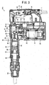
- the impact tool 1 includes a casing having a handle 10, a motor housing 20, and a gear housing 30 connected with one another.
- a power cable 11 is attached to the handle 10.
- the handle 10 houses a switch mechanism 12.
- a trigger 13 that can be manipulated by the user is mechanically connected to the switch mechanism 12.
- the switch mechanism 12 is connected to an external power source (not shown) through the power cable 11. By operating the trigger 13, an electrical motor 21 described later can be connected to and disconnected from the external power source.
- the handle 10 includes a grip 14 that is gripped by the user when the impact tool 1 is used.
- the motor housing 20 is positioned at a lower front side of the handle 10.
- the electrical motor 21 is accommodated in the motor housing 20.
- the electrical motor 21 includes an output shaft 22 that outputs a driving force of the electrical motor.
- a pinion gear 23 is provided on the end of the output shaft 22 and is positioned in the gear housing 30.
- a control unit 24 for controlling a rotation speed of the electrical motor 21 is located on the motor housing 20 behind the electrical motor 21.
- the gear housing 30 includes a motion conversion housing 31 and a hammer housing 32.
- the motion conversion housing 31 is positioned above the motor housing 20 and a rear end of the motion conversion housing 31 is connected to the handle 10.
- the hammer housing 32 is positioned above the motor housing 20.
- a crank shaft 34 that extends parallel to the output shaft 22 is rotatably supported on the rear side of the pinion gear 23 in the motion conversion housing 31.
- a first gear 35 that meshingly engaged with the pinion gear 23 is coaxially fixed to the lower end of the crank shaft 34.
- a motion conversion mechanism 36 is provided at the upper side of the crank shaft 34.
- the motion conversion mechanism 36 includes a crank weight 37, a crank pin 38, and a connecting rod 39.
- the crank weight 37 is fixed to the upper end of the crank shaft 34.
- the crank pin 38 is fixed to the end portion of the crank weight 37.
- the crank pin 38 is inserted into the rear end of the connecting rod 39.
- a rotation transmission shaft 51 extending parallel to the output shaft 22 is rotatably supported on the front side of the pinion gear 23 in the motion conversion housing 31.
- a second gear 52 that meshingly engaged with the pinion gear 23 is coaxially fixed to the lower end of a rotation transmission shaft 51.
- a first bevel gear 51A is coaxially fixed to the upper end of the rotation transmission shaft 51.
- a cylinder 40 extending in a direction perpendicular to the output shaft 22 is provided in the hammer housing 32.
- the center axis of the cylinder 40 and the rotation axis of the output shaft 22 are positioned on a same plane.
- the rear end of the cylinder 40 opposes the electrical motor 21 in the axial direction of the output shaft 22.
- a piston 43 is provided in the cylinder 40 and is slidably provided along the inner periphery of the cylinder 40.
- the piston 43 reciprocates in the axial direction of the cylinder 40.
- the piston 43 includes a piston pin 43A that inserted into the front end of the connecting rod 39.
- a striking member 44 is provided in the front section of the cylinder 40 and is slidably provided along the inner periphery of the cylinder 40 in the axial direction thereof.
- An air chamber 45 is formed among the cylinder 40, the piston 43, and the hammer 44.
- a rotating cylinder 50 is rotatably supported in the hammer housing 32.
- the rotating cylinder 50 surrounds the front section of the outer perimeter of the cylinder 40.
- the rotating cylinder 50 extends forward of the cylinder 40, and a tool support portion 15 is provided at the end of the rotating cylinder 50 and is capable of attaching or detaching a working tool (not shown).
- a second bevel gear 50A that meshingly engaged with the first bevel gear 51A is provided on the rear end portion of the rotating cylinder 50.
- the center axis of the rotating cylinder 50 and the rotation axis of the output shaft 22 are positioned on a same plane.
- an intermediate member 46 is provided in the front side of the striking member 44 and is slidably provided against the rotating cylinder 50. The intermediate member 46 reciprocates in the axial direction of the rotating cylinder 50.
- a counterweight mechanism 70 is provided in the motion conversion housing 31 and in opposition to the handle 10.
- the counterweight mechanism 70 is positioned between a center of gravity G of the impact tool 1 and the grip 14 of the handle 10 and is positioned above the control unit 24.
- the counterweight mechanism 70 will be described while referring to Figs. 1 and 2 .
- the counterweight mechanism 70 includes a pair of support members 71, a pair of support members 72, a counterweight holding member 73, and a counterweight 74.
- the support members 71 and 72 are positioned on a plane perpendicular to the reciprocating direction of the piston 43.
- the support members 71 oppose the support members 72 on the plane.
- the pair of support members 71 is made from rubber and is fixed to the upper section of the motion conversion housing 31.
- the pair of support members 72 is made from steel roller and is fixed to the motion conversion housing 31.
- the counterweight holding member 73 is made from a leaf spring.
- the upper end portion of the counterweight holding member 73 has an L-shaped, is positioned between the pair of support members 71 and is supported by the support members 71 with line contacts. Since the pair of support members 71 is made from rubber, the upper end portion of the counterweight holding member 73 is supported by the support members 71 while being capable of moving up and down with respect to the support members 71.
- the lower end portion of the counterweight holding member 73 is positioned between the pair of support members 72 and is supported by the support members 72 with line contacts. Since the pair of support members 72 is made from the steel roller, the lower end portion of the counterweight holding member 73 is supported by the support members 72 while being capable of moving up and down with respect to the support members 72.
- the counterweight 74 is fixed roughly in the vertical center of the counterweight holding member 73 using a bolt 75.
- the counterweight 74 is doubly supported at its both ends by the counterweight holding member 73.
- the counterweight 74 includes a base 74A and two legs 74B.
- the base 74A extends in a direction perpendicular to the extending direction of the counterweight holding member 73 and is fixed to the counterweight holding member 73.
- Each of the two legs 74B is connected to the ends of the base 74A and extends along and is separated from the counterweight holding member 73.
- the counterweight 74 has an H-shaped.
- the working tool (not shown) is pressed against a workpiece (not shown) with the handle 10 gripped by the user.
- the trigger 12 is pulled to supply power to and rotate the electrical motor 21.
- This rotation driving force is transmitted to the crank shaft 34 by way of the pinion gear 23 and the first gear 35.
- the rotation of the crank shaft 34 is converted into reciprocation motion of the piston 43 in the cylinder 40 by the motion converter mechanism 36 (the crank weight 37, the crank pin 38, and the connecting rod 39).
- the reciprocation motion of the piston 43 leads to repeated increments and decrements the pressure of the air in the air chamber 45, thereby causing a reciprocation motion of the striking member 44.
- the striking member 44 moves forward and collides with the rear end of the intermediate member 46, thereby applying an impact force to the working tool (not shown).
- the rotation driving force of the electrical motor 21 is transmitted to the pinion gear 23, the second gear 52, and the rotation transmission shaft 51.
- the rotation of the rotation transmission shaft 51 is transmitted to the rotating cylinder 50 by way of the first bevel gear 51A and the second bevel gear 50A, resulting in rotation of the rotating cylinder 50.
- the rotation of the rotating cylinder 50 applies a rotation force to the working tool (not shown).
- the workpiece (not shown) is fractured by the rotation force and the impact force described above applied to the working tool (not shown).
- a vibration with a roughly constant frequency resulting from the reciprocation motion of the striking member 44 is generated in the impact tool 1.
- the vibration is transmitted to the support members 71 and 72 by way of the motion conversion housing 31.
- the vibration transmitted to the support members 71 and 72 is transmitted to the counterweight holding member 73 and the counterweight 74, leading to the counterweight 74 vibrating in a direction that the piston 43 reciprocates.
- the vibration of the impact tool 1 can be reduced by the vibration of the counterweight 74, thereby improving the operation of the impact tool 1.
- the vibration of a frequency band having a constant width centering on a resonance frequency is reduced by the vibration of the counterweight 74.
- the resonance frequency is determined by the counterweight 74 and the counterweight holding member 73 which is a leaf spring.
- the resonance frequency is set up to be roughly identical to the frequency of the vibration generated by the impact of the impact tool 1.
- the counterweight 74 Since the counterweight 74 is doubly supported on both ends by the counterweight holding member 73 as described above, rotation moment that would be generated with a cantilevered counterweight can be prevented. Also, the ends of the counterweight holding member 73 are movably supported with respect to the support members 71 and 72. Hence, no friction is generated between the motion conversion housing 31 and the counterweight 74 and the counterweight holding member 73 made from the leaf spring. Accordingly, the counterweight holding member 73 and the counterweight 74 can be vibrated smoothly in the same directions as the directions for the reciprocation motion of the piston 43. Thus, the vibration of the impact tool 1 caused by the reciprocation motion of the striking member 44 can be efficiently reduced, thereby improving the operation of the impact tool 1.
- the counterweight holding member 73 can be prevented from slipping out from the support members 71. Furthermore, the counterweight 74 is the H-shaped. As a result, the length of the counterweight holding member 73 needed to obtain a desired resonance frequency can be reduced, thereby providing a compact overall size for the counterweight mechanism 70.
- the counterweight mechanism 70 is positioned above the control unit 24 and is disposed in opposition to the handle 10, the open space above the control unit 24 can be used effectively and enlargement of the impact tool 1 by providing the counterweight mechanism 70 can be prevented.
- the counterweight mechanism 70 is positioned between the grip 14 and the center of gravity G of the impact tool 1. Therefore, the rotation moment centering on the center of gravity G caused by the reciprocation motion of the piston 43 can be reduced. Also, since springs supporting the counterweight 74 are not placed at ends of the counterweight 74 in the directions of the reciprocation motion of the piston 43, as in conventional impact tools, frication between the housing, and the springs and the counterweight 74 can be prevented. Thus, the vibration of the counterweight 74 can be stabilized and efficiently absorbed.
- the electrical power tool of the present invention is applied to an impact tool 101.
- the impact tool 101 according to the second embodiment does not include the rotating cylinder 50 and the control unit 24 used in the impact tool 1 of the first embodiment. Therefore, no rotation is applied to the working tool during the operation of the impact tool 1, and the electrical motor 21 rotates at a fixed speed.
- a counterweight mechanism 170 is provided in the motion conversion housing 31 and is disposed in opposition to the handle 10.
- the counterweight mechanism 170 includes a support member 171, a pair of support members 172, a counterweight holding member 173, and a counterweight 174.
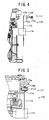
- the support member 171 will be described while referring to Figs. 4 and 5 .
- the support member 171 includes a bolt 171A, a washer 171B, and a spacer 171C.
- the pair of support members 172 is made from rubber.
- the counterweight holding member 173 is made from a leaf spring and is formed with a bolt insertion hole 173a.
- the upper end portion of the counterweight holding member 173 is fixed to the motion conversion housing 31 by inserting the bolt 171A through the washer 171B, the spacer 171C, and the bolt insertion hole 173a.
- the lower end portion of the counterweight holding member 173 is positioned between the pair of the support members 172 and is supported by the support members 172 with line contacts. Since the support members 172 is made from rubber, the lower end portion of the counterweight holding member 173 is supported by the support members 172 while being capable of moving up and down with respect to the support members 172.
- the counterweight 174 is fixed roughly in the vertical center of the counterweight holding member 173.
- the counterweight mechanism 170 of the second embodiment also can be efficiently reduced the vibration of the impact tool 101 caused by the reciprocation motion of the striking member 44.
- the counterweight mechanism 170 includes the bolt 171A, the washer 171B, and the spacer 171C.
- the load applied to the upper end portion of the counterweight holding member 173 can be controlled.
- the vibration of the counterweight holding member 173 and the counterweight 174 can be controlled and the resonance frequency of the counterweight mechanism 170 can be adjusted.
- Other advantages of the impact tool 101 are similar to the advantages of the impact tool 1 according to the first embodiment.
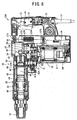
- FIG. 6 An electrical power tool according to a third embodiment of the present invention will be described while referring to Fig. 6 .
- the electrical power tool of the present invention is applied to an impact tool 201.
- Like parts and components that are the same as those of the first embodiment will be assigned the same reference numerals to avoid duplicating descriptions, and only different aspects will be described.
- a counterweight mechanism 270 is provided in the motion conversion housing 31 and is disposed in opposition to the handle 10.
- the counterweight mechanism 270 is positioned above the control unit 24 and is also positioned above a line that passes through the center of gravity G of the impact tool 201 and that extends parallel to the directions of the reciprocation motion of the piston 43.
- the counterweight mechanism 270 includes a pair of support members 271, a pair of support members 272, a counterweight holding member 273, and a counterweight 274.
- the pair of support members 271 is made from rubber and is fixed to the upper section of the motion conversion housing 31.
- the pair of support members 272 is also made from rubber and is fixed to the motion conversion housing 31.
- the counterweight holding member 273 is made from a leaf spring.
- the upper end portion of the counterweight holding member 273 is positioned between the pair of support members 271 and is supported by the support members 271 with line contacts. Since the pair of support members 271 is made from rubber, the upper end portion of the counterweight holding member 273 is supported by the support members 271 while being capable of moving up and down with respect to the support members 271.
- the lower end of the counterweight holding member 273 is positioned between the pair of support members 272 and is supported by the support members 272 with line contact. Since the pair of support members 272 is made from rubber, the lower end portion of the counterweight holding member 273 is supported by the support members 272 while being capable of moving up and down with respect to the support members 272.
- the counterweight 274 is doubly supported on both ends by the counterweight holding member 273.
- the counterweight 274 is fixed to roughly in the vertical center of the counterweight holding member 273.
- the counterweight mechanism 270 according to the third embodiment also can be efficiently reduced the vibration of the impact tool 201 caused by the reciprocation motion of the striking member 44. Also, as described above, the counterweight mechanism 270 is positioned above the line that passes through the center of gravity G of the impact tool 201 and that extends parallel to the directions of the reciprocation motion of the piston 43. Therefore, the rotation moment centering on the center of gravity G caused by the reciprocation motion of the piston 43 can be reduced. Other advantages of the impact tool 201 are similar to the advantages of the impact tool 1 of the first embodiment.
- FIG. 7 An electrical power tool according to a fourth embodiment of the present invention will be described while referring to Fig. 7 .
- the electrical power tool of the present invention is applied to an impact tool 301.
- Like parts and components that are the same as those of the first embodiment will be assigned the same reference numerals to avoid duplicating descriptions, and only different aspects will be described.
- the crank shaft 34 is positioned at the front side of the pinion gear 23.
- a third gear 34A is coaxially fixed to the crank shaft 34 on the lower side of the first gear 35.
- the rotation transmission shaft 51 is positioned at the front side of the crank shaft 34.
- the second gear 52 is meshingly engaged with the third gear 34A.
- the rotation of the electrical motor 21 is transmitted to the rotation transmission shaft 51 by way of the pinion gear 23, the first gear 35, the third gear 34A, and the second gear 52.
- the rotation of the rotation transmission shaft 51 is transmitted to the rotating cylinder 50 by way of the first bevel gear 51A and the second bevel gear 50A, resulting in rotation of the rotating cylinder 50.
- the rotation of the rotating cylinder 50 applies a rotation force to a working tool (not shown).
- a counterweight mechanism 370 is provided in a space above the electrical motor 21. The space is created by positioning the crank shaft 34 on the front side of the pinion gear 23.
- the counterweight mechanism 370 includes a support member 371, a support member 372, a counterweight holding member 373, and a counterweight 374.
- the support members 371 and 372 have a U-shaped, and the opening of the support member 371 opposes the opening of the support member 372 with each other.
- the counterweight holding member 373 is made from a leaf spring, and each end thereof is inserted into the openings of the support members 371 and 372, respectively.
- the counterweight holding member 373 is supported by the support members 371 and 372 with line contacts.
- the counterweight 374 is fixed to roughly in the vertical center of the counterweight holding member 373. Thus, the counterweight 374 is doubly supported on both ends by the counterweight holding member 373.
- the counterweight mechanism 370 according to fourth embodiment also can be efficiently reduced the vibration of the impact tool 301 caused by the reciprocation motion of the striking member 44. Also, as described above, the counterweight mechanism 370 is positioned in a space above the electrical motor 21 created by positioning the crank shaft 34 on the front side of the pinion gear 23. Accordingly, the open space above the electrical motor 21 can be used efficiently and enlargement of the impact tool 301 by providing the counterweight mechanism 370 can be prevented. Other advantages of the impact tool 301 are similar to the advantages of the impact tool 1 according to the first embodiment.
- FIG. 8 An electrical power tool according to a fifth embodiment of the present invention will be described while referring to Fig. 8 .
- the electrical power tool of the present invention is applied to an impact tool 401.
- Like parts and components that are the same as those of the first embodiment will be assigned the same reference numerals to avoid duplicating descriptions, and only different aspects will be described.
- a counterweight mechanism 470 is provided above the control unit 24 and is disposed in opposition to the handle 10.
- the counterweight mechanism 470 includes two support members 471, four springs 473, and two counterweights 474.
- the two support members 471 extend parallel to the directions of the reciprocation motion of the piston 43 and are fixed to the motion conversion housing 31.
- Each of the two counterweights 474 is slidably supported by the support members 471, respectively.
- Each of the four springs 473 is positioned on each ends of the counterweights 474 and is interposed between the counterweights 474 and the motion conversion housing 31.
- the counterweight mechanism 470 according to this embodiment also can be reduced efficiently the vibration of the impact tool 401, which is caused by the reciprocation motion of the striking member 44, by the vibration of the counterweights 474.
- Other advantages of the impact tool 401 are similar to the advantages of the impact tool 1 according to the first embodiment.
- the electrical power tool of the present invention is applied to an impact tool 501.
- the impact tool 501 includes a casing having the handle 10, the motor housing 20, a weight housing 60, and a gear housing 80.
- the power cable 11 is attached to the handle 10.
- the handle 10 houses the switch mechanism 12.
- the trigger 13 that can be manipulated by the user is mechanically connected to the switch mechanism 12.
- the switch mechanism 12 is connected to an external power source (not shown) through power cable 11. By operating the trigger 13, the switch mechanism 12 can be connected to and disconnected from the external power source.
- the motor housing 20 is provided on the front side of the handle 10.
- the handle 10 and the motor housing 20 are formed integrally from plastic.
- the electrical motor 21 is accommodated in the motor housing 20.
- the electrical motor 21 includes the output shaft 22 and outputs rotational drive force.
- the weight housing 60 is located on the front side of the motor housing 20 and is made from resin.
- the weight housing 60 includes a first weight housing 60A opposing the motor housing 20 and a second weight housing 60B opposing the gear housing 80.
- a first intermediate shaft 61 is provided in the weight housing 60 and extends in a direction that the output shaft 22 extends.
- the first intermediate shaft 61 is rotatably support by bearings 62 and 63.
- the rear end portion of the first intermediate shaft 61 is connected to the output shaft 22.
- the front end portion of the first intermediate shaft 61 is positioned in the gear housing 80 and is provided with a fourth gear 61A.
- a counterweight mechanism 570 is provided in the weight housing 60.
- the counterweight mechanism 570 includes support members 571 and 572, a pair of counterweight holding members 573, a counterweight 574, and a bolt 575.
- the support members 571 and 572 are provided at the upper and lower end portions of the second weight housing 60B, respectively.
- the pair of counterweight holding members 573 is made from leaf springs. As shown in Fig.
- the upper and lower end portions of the counterweight holding members 573 have roughly an L-shaped, and each of the distal ends of the upper and lower end portions of the counterweight holding members 573 is positioned in each of recesses 60c formed in the second weight housing 60B, respectively.
- the upper end portion of the counterweight holding members 573 is supported by the support member 571, and the lower end portion of the counterweight holding members 573 is supported by the support member 572.
- the counterweight 574 has a roughly circular cross-section and is formed with a shaft insertion hole 574a formed at the center thereof.
- the counterweight 574 is fixed to the counterweight holding members 573 by bolts 575. Hence, the counterweight 574 is doubly supported on its both ends by the pair of counterweight holding members 573.
- the first intermediate shaft 61 is inserted through the shaft insertion hole 574a.
- the gear housing 80 is located on the front side of the second weight housing 60B and is made from resin.
- a metal partition member 80A is disposed in the gear housing 80 and partitions the gear housing 80 and the weight housing 60.
- the gear housing 80 and the partition member 80A forms a decelerating chamber 80a, which is a mechanism chamber accommodating a rotation transmission mechanism described later.
- a second intermediate shaft 82 is rotatably supported on the gear housing 80 and the partition member 80A via a bearings 82B and 82C, and extends parallel to the output shaft 22.
- a side handle 16 is provided near the tool support portion 15 of the gear housing 80, described later.
- a fifth gear 81 meshingly engaged with the fourth gear 61A is coaxially fixed to the second intermediate shaft 82 on the electrical motor 21 side thereof.
- a gear 82A is formed on the front end portion of the second intermediate shaft 82 to be meshingly engaged with a sixth gear 83, described later.
- a cylinder 84 is provided above the second intermediate shaft 82 in the gear housing 80. The cylinder 84 extends parallel to the second intermediate shaft 82 and is rotatably supported on the partition member 80A.
- the sixth gear 83 is fixed to the outer periphery of the cylinder 84 and is meshingly engaged with the gear 82A described above so that the cylinder 84 can rotate around its central axial.
- the tool support portion 15 mentioned above is provided on the front side of the cylinder 84, and a working tool (not shown) is capable of attaching to or detaching from the tool support portion 15.
- a clutch 86 is splined to the intermediate section of the second intermediate shaft 82.
- the clutch 86 is urged by a spring toward the electrical motor 21.
- the clutch 86 can be switched by means of a change lever 87 positioned below the gear housing 80 between a hammer drill mode (the position shown in Fig. 9 ) and a drill mode (with the clutch 86 moved toward the front).
- a motion converter 90 that converts rotational motion into reciprocation motion is rotatably provided on the outer periphery of the second intermediate shaft 82 on the electrical motor 21 side of the clutch 86.
- the motion converter 90 has an arm 90A that is capable of reciprocating back-and-forth the impact tool 501 as a result of the rotation of the second intermediate shaft 82.
- the motion converter 90 is connected to and work with a piston 92 provided in the cylinder 84 through a piston pin 91.
- the piston 92 is slidably mounted in the cylinder 84 and is capable of a reciprocation motion parallel to the second intermediate shaft 82.
- a striking member 93 is provided in the piston 92 and is slidably provided along the inner periphery of the cylinder 84.
- An air chamber 94 is formed among the cylinder 84, the piston 92, and the striking member 93.
- An intermediate member 95 is supported in the cylinder 84 on the opposite side of the striking member 93 from the air chamber 94.
- the intermediate member 95 is slidably provided against the cylinder 84 along the direction of the motion of the piston 92.
- a working tool (not shown) is positioned on the opposite side of the intermediate member 95 from the striking member 93. Hence, the striking member 93 strikes the working tool (not shown) through the intermediate member 95.
- Rotation output of the motor 21 is transmitted to the second intermediate shaft 82 by way of the first intermediate shaft 61, the fourth gear 61A, and the fifth gear 81.
- the rotation of the second intermediate shaft 82 is transmitted to the cylinder 84 by way of the meshing between the gear 82A and the sixth gear 83 mounted to the outer periphery of the cylinder 84.
- the clutch 86 is in the hammer drill mode by operating the change lever 87, the clutch 86 is connected to the motion converter 90.
- the rotational driving force of the second intermediate shaft 82 is transmitted to the motion converter 90 through the clutch 86.
- the rotational driving force is converted to the reciprocation motion of the piston 92 on the motion converter 90 by way of the piston pin 91.
- the reciprocation motion of the piston 92 causes the pressure of the air inside the air chamber 94 formed between the striking member 93 and the piston 92 to repeatedly increase and decrease, thereby causing a reciprocation motion of the striking member 93.
- the striking member 93 moves forward and collides with the rear end of the intermediate member 95, the impact force is applied to the working tool (not shown) through the intermediate element 95. In this manner, the rotational force and the impact force are simultaneously applied to the working tool (not shown) in the hammer drill mode.
- the clutch 86 disengages the connection between the second intermediate shaft 82 and the motion converter 90, and only the rotational driving force of the second intermediate shaft 82 is transmitted to the cylinder 84 through the gear 82A and the sixth gear 83. Accordingly, only rotational force is applied to the working tool (not shown).
- a vibration having a roughly constant frequency is generated in the impact tool 501 due to the reciprocation motion of the striking member 93.
- the vibration is transmitted to the support members 571 and 572 by way of the second weight housing 60B.
- the vibration transmitted to the support members 571 and 572 is transmitted to the counterweight holding members 573 and the counterweight 574, and the counterweight 574 vibrates in the same directions as the directions of the reciprocation motion of the piston 92.
- the vibration of the impact tool 501 can be reduced by the vibration of the counterweight 574, thereby improving the operation of the impact tool 501.
- the pair of support members 72 of the impact tool 1 according to the first embodiment is made from steel roller, but the present invention is not limited to the steel roller. Any component having good sliding properties, e.g., an oil-impregnated metal, can be used.
- the shape of the counterweight 174 it would also be possible as shown in Fig. 11 for the shape of the counterweight 174 to be, when the impact tool 101 is seen from the side, an "H" shape formed from: a base 174A extending in a direction perpendicular to the direction in which the weight support member 173 extends and secured to the weight support member 173; and two legs 174B extended from the ends of the base 174A, extending on either side of but separated from the weight support member 173.
- the length of the weight support member 173 needed to obtain a desired resonance frequency can be reduced, making it possible to provide a compact overall design for the counterweight unit.
Landscapes
- Engineering & Computer Science (AREA)
- Mechanical Engineering (AREA)
- Percussive Tools And Related Accessories (AREA)
Claims (4)
- Outil d'impact (1) comprenant :un boîtier (20, 30) :un moteur (21) ayant un axe de rotation (22), le moteur étant logé dans le boîtier et générant une force d'entraînement en rotation lorsqu'il est alimenté,un convertisseur de mouvement alternatif (36) configuré pour convertir la force d'entraînement de rotation du moteur en un mouvement de va et vient dans des directions perpendiculaires à l'axe de rotation du moteur,une mèche d'outil fixée à une partie d'extrémité (15) du boîtier et entraînée par le mouvement de va et vient du convertisseur en mouvement de va et vient,une poignée (10) positionnée à une autre partie d'extrémité du boîtier et comprenant une prise (14), etun mécanisme de contrepoids (70) pouvant être actionné pour réduire les vibrations générées liées au mouvement de va et vient, le mécanisme de contrepoids étant disposé dans une section du boîtier,caractérisé en ce quele mécanisme de contrepoids disposé entre la prise et le centre de gravité (G) de l'outil d'impact.
- Outil d'impact selon la revendication 1, dans lequel le mécanisme de contrepoids comporte un contrepoids (74) et un élément de support de contrepoids (71, 72) supportant le contrepoids et comportant un ressort à lame qui s'étend dans la même direction que la prise (14).
- Outil d'impact (1) selon la revendication 1 2, dans lequel une extrémité de l'élément de support de contrepoids (71, 72) est solidement fixée au boîtier (20, 30).
- Outil d'impact (1) selon la revendication 3, dans lequel également une autre extrémité de l'élément de support de contrepoids (71, 72) est solidement fixée au boîtier (20, 30).
Applications Claiming Priority (1)
| Application Number | Priority Date | Filing Date | Title |
|---|---|---|---|
| JP2006060969A JP5041575B2 (ja) | 2006-03-07 | 2006-03-07 | 打撃工具 |
Publications (2)
| Publication Number | Publication Date |
|---|---|
| EP1832394A1 EP1832394A1 (fr) | 2007-09-12 |
| EP1832394B1 true EP1832394B1 (fr) | 2015-06-24 |
Family
ID=38171562
Family Applications (1)
| Application Number | Title | Priority Date | Filing Date |
|---|---|---|---|
| EP07004702.2A Active EP1832394B1 (fr) | 2006-03-07 | 2007-03-07 | Outil d'impact doté d'un mécanisme de contrôle des vibrations |
Country Status (4)
| Country | Link |
|---|---|
| US (1) | US7513317B2 (fr) |
| EP (1) | EP1832394B1 (fr) |
| JP (1) | JP5041575B2 (fr) |
| CN (1) | CN101032814B (fr) |
Families Citing this family (37)
| Publication number | Priority date | Publication date | Assignee | Title |
|---|---|---|---|---|
| WO2007102449A1 (fr) * | 2006-03-07 | 2007-09-13 | Hitachi Koki Co., Ltd. | Outil d'alimentation electrique |
| JP4756474B2 (ja) * | 2006-07-20 | 2011-08-24 | 日立工機株式会社 | 電動工具 |
| US8261854B2 (en) * | 2007-05-01 | 2012-09-11 | Hitachi Koki Co., Ltd | Reciprocating tool |
| GB0804963D0 (en) * | 2008-03-18 | 2008-04-16 | Black & Decker Inc | Hammer |
| EP2127820A1 (fr) * | 2008-05-26 | 2009-12-02 | Max Co., Ltd. | Outil d'enfoncement |
| JP5214343B2 (ja) * | 2008-06-19 | 2013-06-19 | 株式会社マキタ | 作業工具 |
| DE102009014970A1 (de) * | 2009-03-18 | 2010-09-23 | C. & E. Fein Gmbh | Oszillationswerkzeug mit Vibrationsdämpfung |
| JP5496190B2 (ja) * | 2009-05-20 | 2014-05-21 | リョービ株式会社 | インパクト工具 |
| DE102009022088A1 (de) | 2009-05-20 | 2010-11-25 | Friedrich Duss Maschinenfabrik Gmbh & Co.Kg | Elektrowerkzeugmaschine, insbesondere handgeführter Bohrhammer |
| DE102009054723A1 (de) * | 2009-12-16 | 2011-06-22 | Robert Bosch GmbH, 70469 | Handwerkzeugmaschine |
| US8517730B2 (en) * | 2009-12-31 | 2013-08-27 | King Saud University | Tooth extraction tool |
| JP5600955B2 (ja) * | 2010-02-11 | 2014-10-08 | 日立工機株式会社 | インパクト工具 |
| JP5582337B2 (ja) * | 2010-04-27 | 2014-09-03 | 日立工機株式会社 | 電動工具 |
| US20120048580A1 (en) * | 2010-09-01 | 2012-03-01 | Hilti Aktiengesellschaft | Power tool |
| CN103328159B (zh) * | 2011-01-10 | 2015-12-16 | 博世电动工具(中国)有限公司 | 冲击工具 |
| DE102011017579A1 (de) * | 2011-04-27 | 2012-10-31 | Hilti Aktiengesellschaft | Werkzeugmaschine und Steuerungsverfahren |
| GB201112825D0 (en) * | 2011-07-26 | 2011-09-07 | Black & Decker Inc | A hammer drill |
| US9808925B2 (en) | 2012-03-22 | 2017-11-07 | Hitachi Koki Co., Ltd. | Impact tool |
| JP2013193186A (ja) * | 2012-03-22 | 2013-09-30 | Hitachi Koki Co Ltd | 電動工具 |
| US8966773B2 (en) | 2012-07-06 | 2015-03-03 | Techtronic Power Tools Technology Limited | Power tool including an anti-vibration handle |
| CN104837427B (zh) | 2012-11-14 | 2017-09-22 | 不列颠哥伦比亚癌症机构分部 | 管状锤钻配件 |
| US9981372B2 (en) | 2012-12-31 | 2018-05-29 | Robert Bosch Tool Corporation | Reciprocating tool with fluid driven counterweight |
| US9597784B2 (en) | 2013-08-12 | 2017-03-21 | Ingersoll-Rand Company | Impact tools |
| EP2848370A1 (fr) * | 2013-09-12 | 2015-03-18 | HILTI Aktiengesellschaft | Machine-outil manuelle |
| US9539715B2 (en) | 2014-01-16 | 2017-01-10 | Ingersoll-Rand Company | Controlled pivot impact tools |
| CN106457543B (zh) * | 2014-04-30 | 2019-11-19 | 工机控股株式会社 | 作业工具 |
| JP6278830B2 (ja) * | 2014-05-16 | 2018-02-14 | 株式会社マキタ | 打撃工具 |
| EP3461593A1 (fr) * | 2017-09-30 | 2019-04-03 | Positec Power Tools (Suzhou) Co., Ltd | Outil de percussion |
| WO2019079560A1 (fr) | 2017-10-20 | 2019-04-25 | Milwaukee Electric Tool Corporation | Outil à percussion |
| JP6987599B2 (ja) * | 2017-10-20 | 2022-01-05 | 株式会社マキタ | 打撃工具 |
| CN214723936U (zh) | 2018-01-26 | 2021-11-16 | 米沃奇电动工具公司 | 冲击工具 |
| US11571796B2 (en) | 2018-04-04 | 2023-02-07 | Milwaukee Electric Tool Corporation | Rotary hammer |
| US12021437B2 (en) | 2019-06-12 | 2024-06-25 | Milwaukee Electric Tool Corporation | Rotary power tool |
| JP2021037560A (ja) * | 2019-08-30 | 2021-03-11 | 株式会社マキタ | 電動作業機 |
| US11826891B2 (en) * | 2019-10-21 | 2023-11-28 | Makita Corporation | Power tool having hammer mechanism |
| EP3901498A1 (fr) * | 2020-04-21 | 2021-10-27 | Hilti Aktiengesellschaft | Mécanisme de percussion électropneumatique |
| US11759938B2 (en) | 2021-10-19 | 2023-09-19 | Makita Corporation | Impact tool |
Family Cites Families (28)
| Publication number | Priority date | Publication date | Assignee | Title |
|---|---|---|---|---|
| US1845825A (en) * | 1927-07-22 | 1932-02-16 | Chicago Pneumatic Tool Co | Spring handle attachment for rock drills |
| US3305031A (en) * | 1965-02-01 | 1967-02-21 | Ingersoll Rand Co | Power hammer |
| JPS5337503B2 (fr) * | 1972-04-13 | 1978-10-09 | ||
| JPS54127080A (en) * | 1978-03-25 | 1979-10-02 | Makoto Nandate | Vibration isolation device in handle of machine in which vibration is formed |
| DE3122979A1 (de) * | 1981-06-10 | 1983-01-05 | Hilti AG, 9494 Schaan | Bohr- oder meisselhammer |
| JPS61178188A (ja) * | 1985-02-01 | 1986-08-09 | 芝浦メカトロニクス株式会社 | 無反動衝撃工具 |
| JPS61228139A (ja) * | 1985-03-29 | 1986-10-11 | Hitachi Zosen Corp | 振動減衰装置 |
| DE3546029C2 (de) * | 1985-12-24 | 1997-03-13 | Stihl Maschf Andreas | Handgeführtes, verbrennungsmotorisch angetriebenes Arbeitsgerät |
| JP2598703Y2 (ja) * | 1992-10-14 | 1999-08-16 | 株式会社共立 | 防振用コイルばねの取り付け構造 |
| EP0837757B1 (fr) * | 1995-07-13 | 2001-10-17 | Atlas Copco Berema Aktiebolag | Systemes de poignees pour perforatrices a main |
| DE19646622B4 (de) * | 1996-11-12 | 2004-07-01 | Wacker Construction Equipment Ag | An einem Handgriff führbares Arbeitsgerät |
| DE19714288A1 (de) * | 1997-04-07 | 1998-10-08 | Hilti Ag | Bohr- und/oder Meisselgerät |
| DE10033362A1 (de) * | 2000-07-08 | 2002-01-17 | Hilti Ag | Elektrohandwerkzeug mit Leerschlagabschaltung |
| DE10136015A1 (de) * | 2001-07-24 | 2003-02-13 | Bosch Gmbh Robert | Handwerkzeugmaschine mit vibrationsgedämpftem Handgriff |
| DE10136515C2 (de) * | 2001-07-26 | 2003-10-23 | Wacker Construction Equipment | Bohr- und/oder Schlaghammer mit Handgriff |
| DE10240361A1 (de) * | 2002-09-02 | 2004-03-11 | Hilti Ag | Drehende und schlagende Elektrohandwerkzeugmaschine |
| DE10255162A1 (de) * | 2002-11-22 | 2004-06-03 | Hilti Ag | Vibrationsentkoppelte Schlagwerksbaugruppe |
| JP4270887B2 (ja) * | 2003-01-10 | 2009-06-03 | 株式会社マキタ | 電動往復動式工具 |
| JP4195818B2 (ja) * | 2003-01-16 | 2008-12-17 | 株式会社マキタ | 電動ハンマ |
| JP2004255542A (ja) * | 2003-02-27 | 2004-09-16 | Makita Corp | 打撃工具 |
| DE10309012B3 (de) * | 2003-03-01 | 2004-08-12 | Hilti Ag | Steuerverfahren einer axial schlagenden und drehenden Elektrohandwerkzeugmaschine |
| EP1606082B1 (fr) * | 2003-03-21 | 2010-05-05 | BLACK & DECKER INC. | Outil electrique incorporant un systeme limitant les vibrations |
| EP1464449B1 (fr) * | 2003-04-01 | 2010-03-24 | Makita Corporation | Outil électrique |
| JP4155857B2 (ja) | 2003-04-01 | 2008-09-24 | 株式会社マキタ | 作業工具 |
| GB2407791A (en) * | 2003-11-04 | 2005-05-11 | Black & Decker Inc | Vibration reduction apparatus for a power tool |
| JP4647957B2 (ja) * | 2004-08-27 | 2011-03-09 | 株式会社マキタ | 作業工具 |
| DE602004003383T8 (de) * | 2004-09-13 | 2008-01-17 | Makita Corp., Anjo | Verfahren zur Herstellung eines Kraftwerkzeugs |
| GB2429675A (en) * | 2005-06-23 | 2007-03-07 | Black & Decker Inc | Vibration dampening mechanism |
-
2006
- 2006-03-07 JP JP2006060969A patent/JP5041575B2/ja active Active
-
2007
- 2007-03-07 CN CN2007100854651A patent/CN101032814B/zh active Active
- 2007-03-07 EP EP07004702.2A patent/EP1832394B1/fr active Active
- 2007-03-07 US US11/682,937 patent/US7513317B2/en active Active
Also Published As
| Publication number | Publication date |
|---|---|
| US7513317B2 (en) | 2009-04-07 |
| US20080277128A1 (en) | 2008-11-13 |
| JP2007237304A (ja) | 2007-09-20 |
| CN101032814A (zh) | 2007-09-12 |
| EP1832394A1 (fr) | 2007-09-12 |
| CN101032814B (zh) | 2012-07-04 |
| JP5041575B2 (ja) | 2012-10-03 |
Similar Documents
| Publication | Publication Date | Title |
|---|---|---|
| EP1832394B1 (fr) | Outil d'impact doté d'un mécanisme de contrôle des vibrations | |
| EP2012978B1 (fr) | Outil d'alimentation electrique | |
| US7637328B2 (en) | Electrical power tool having vibration control mechanism | |
| EP2138278B1 (fr) | Poignée pour un outil électrique | |
| EP2000264B1 (fr) | Machine-outil avec réducteur dynamique de vibrations | |
| EP1529603B1 (fr) | Système limitant les vibrations pour outil électrique, et outil incorporant ce système | |
| EP1818141B1 (fr) | Système limitant les vibrations pour outil électrique, et outil électrique incorporant ce système | |
| JP4793755B2 (ja) | 電動工具 | |
| EP2159008B1 (fr) | Outil d'impact | |
| US8668026B2 (en) | Power tool comprising a dynamic vibration reducer | |
| US7472760B2 (en) | Vibration reduction apparatus for power tool and power tool incorporating such apparatus | |
| JP2007175836A (ja) | 打撃工具 | |
| JP5327726B2 (ja) | 打撃工具 | |
| JP4577240B2 (ja) | 電動工具 |
Legal Events
| Date | Code | Title | Description |
|---|---|---|---|
| PUAI | Public reference made under article 153(3) epc to a published international application that has entered the european phase |
Free format text: ORIGINAL CODE: 0009012 |
|
| AK | Designated contracting states |
Kind code of ref document: A1 Designated state(s): AT BE BG CH CY CZ DE DK EE ES FI FR GB GR HU IE IS IT LI LT LU LV MC MT NL PL PT RO SE SI SK TR |
|
| AX | Request for extension of the european patent |
Extension state: AL BA HR MK YU |
|
| 17P | Request for examination filed |
Effective date: 20080312 |
|
| 17Q | First examination report despatched |
Effective date: 20080423 |
|
| AKX | Designation fees paid |
Designated state(s): AT BE BG CH CY CZ DE DK EE ES FI FR GB GR HU IE IS IT LI LT LU LV MC MT NL PL PT RO SE SI SK TR |
|
| GRAP | Despatch of communication of intention to grant a patent |
Free format text: ORIGINAL CODE: EPIDOSNIGR1 |
|
| INTG | Intention to grant announced |
Effective date: 20150106 |
|
| RIN1 | Information on inventor provided before grant (corrected) |
Inventor name: SATOU, SHINICHIROU |
|
| GRAS | Grant fee paid |
Free format text: ORIGINAL CODE: EPIDOSNIGR3 |
|
| GRAA | (expected) grant |
Free format text: ORIGINAL CODE: 0009210 |
|
| AK | Designated contracting states |
Kind code of ref document: B1 Designated state(s): AT BE BG CH CY CZ DE DK EE ES FI FR GB GR HU IE IS IT LI LT LU LV MC MT NL PL PT RO SE SI SK TR |
|
| REG | Reference to a national code |
Ref country code: GB Ref legal event code: FG4D |
|
| REG | Reference to a national code |
Ref country code: DE Ref legal event code: R081 Ref document number: 602007041857 Country of ref document: DE Owner name: KOKI HOLDINGS CO., LTD., JP Free format text: FORMER OWNER: HITACHI KOKI CO., LTD., TOKIO/TOKYO, JP |
|
| REG | Reference to a national code |
Ref country code: CH Ref legal event code: EP |
|
| REG | Reference to a national code |
Ref country code: AT Ref legal event code: REF Ref document number: 732696 Country of ref document: AT Kind code of ref document: T Effective date: 20150715 |
|
| REG | Reference to a national code |
Ref country code: IE Ref legal event code: FG4D |
|
| REG | Reference to a national code |
Ref country code: DE Ref legal event code: R096 Ref document number: 602007041857 Country of ref document: DE |
|
| PG25 | Lapsed in a contracting state [announced via postgrant information from national office to epo] |
Ref country code: LT Free format text: LAPSE BECAUSE OF FAILURE TO SUBMIT A TRANSLATION OF THE DESCRIPTION OR TO PAY THE FEE WITHIN THE PRESCRIBED TIME-LIMIT Effective date: 20150624 Ref country code: FI Free format text: LAPSE BECAUSE OF FAILURE TO SUBMIT A TRANSLATION OF THE DESCRIPTION OR TO PAY THE FEE WITHIN THE PRESCRIBED TIME-LIMIT Effective date: 20150624 |
|
| REG | Reference to a national code |
Ref country code: AT Ref legal event code: MK05 Ref document number: 732696 Country of ref document: AT Kind code of ref document: T Effective date: 20150624 |
|
| REG | Reference to a national code |
Ref country code: LT Ref legal event code: MG4D |
|
| PG25 | Lapsed in a contracting state [announced via postgrant information from national office to epo] |
Ref country code: BG Free format text: LAPSE BECAUSE OF FAILURE TO SUBMIT A TRANSLATION OF THE DESCRIPTION OR TO PAY THE FEE WITHIN THE PRESCRIBED TIME-LIMIT Effective date: 20150924 Ref country code: LV Free format text: LAPSE BECAUSE OF FAILURE TO SUBMIT A TRANSLATION OF THE DESCRIPTION OR TO PAY THE FEE WITHIN THE PRESCRIBED TIME-LIMIT Effective date: 20150624 Ref country code: GR Free format text: LAPSE BECAUSE OF FAILURE TO SUBMIT A TRANSLATION OF THE DESCRIPTION OR TO PAY THE FEE WITHIN THE PRESCRIBED TIME-LIMIT Effective date: 20150925 |
|
| REG | Reference to a national code |
Ref country code: NL Ref legal event code: MP Effective date: 20150624 |
|
| PG25 | Lapsed in a contracting state [announced via postgrant information from national office to epo] |
Ref country code: EE Free format text: LAPSE BECAUSE OF FAILURE TO SUBMIT A TRANSLATION OF THE DESCRIPTION OR TO PAY THE FEE WITHIN THE PRESCRIBED TIME-LIMIT Effective date: 20150624 |
|
| REG | Reference to a national code |
Ref country code: FR Ref legal event code: PLFP Year of fee payment: 10 |
|
| PG25 | Lapsed in a contracting state [announced via postgrant information from national office to epo] |
Ref country code: IS Free format text: LAPSE BECAUSE OF FAILURE TO SUBMIT A TRANSLATION OF THE DESCRIPTION OR TO PAY THE FEE WITHIN THE PRESCRIBED TIME-LIMIT Effective date: 20151024 Ref country code: PT Free format text: LAPSE BECAUSE OF FAILURE TO SUBMIT A TRANSLATION OF THE DESCRIPTION OR TO PAY THE FEE WITHIN THE PRESCRIBED TIME-LIMIT Effective date: 20151026 Ref country code: AT Free format text: LAPSE BECAUSE OF FAILURE TO SUBMIT A TRANSLATION OF THE DESCRIPTION OR TO PAY THE FEE WITHIN THE PRESCRIBED TIME-LIMIT Effective date: 20150624 Ref country code: SK Free format text: LAPSE BECAUSE OF FAILURE TO SUBMIT A TRANSLATION OF THE DESCRIPTION OR TO PAY THE FEE WITHIN THE PRESCRIBED TIME-LIMIT Effective date: 20150624 Ref country code: RO Free format text: LAPSE BECAUSE OF NON-PAYMENT OF DUE FEES Effective date: 20150624 Ref country code: CZ Free format text: LAPSE BECAUSE OF FAILURE TO SUBMIT A TRANSLATION OF THE DESCRIPTION OR TO PAY THE FEE WITHIN THE PRESCRIBED TIME-LIMIT Effective date: 20150624 Ref country code: PL Free format text: LAPSE BECAUSE OF FAILURE TO SUBMIT A TRANSLATION OF THE DESCRIPTION OR TO PAY THE FEE WITHIN THE PRESCRIBED TIME-LIMIT Effective date: 20150624 Ref country code: ES Free format text: LAPSE BECAUSE OF FAILURE TO SUBMIT A TRANSLATION OF THE DESCRIPTION OR TO PAY THE FEE WITHIN THE PRESCRIBED TIME-LIMIT Effective date: 20150624 |
|
| REG | Reference to a national code |
Ref country code: DE Ref legal event code: R097 Ref document number: 602007041857 Country of ref document: DE |
|
| PG25 | Lapsed in a contracting state [announced via postgrant information from national office to epo] |
Ref country code: IT Free format text: LAPSE BECAUSE OF FAILURE TO SUBMIT A TRANSLATION OF THE DESCRIPTION OR TO PAY THE FEE WITHIN THE PRESCRIBED TIME-LIMIT Effective date: 20150624 Ref country code: DK Free format text: LAPSE BECAUSE OF FAILURE TO SUBMIT A TRANSLATION OF THE DESCRIPTION OR TO PAY THE FEE WITHIN THE PRESCRIBED TIME-LIMIT Effective date: 20150624 |
|
| PLBE | No opposition filed within time limit |
Free format text: ORIGINAL CODE: 0009261 |
|
| STAA | Information on the status of an ep patent application or granted ep patent |
Free format text: STATUS: NO OPPOSITION FILED WITHIN TIME LIMIT |
|
| 26N | No opposition filed |
Effective date: 20160329 |
|
| PG25 | Lapsed in a contracting state [announced via postgrant information from national office to epo] |
Ref country code: BE Free format text: LAPSE BECAUSE OF NON-PAYMENT OF DUE FEES Effective date: 20160331 Ref country code: SI Free format text: LAPSE BECAUSE OF FAILURE TO SUBMIT A TRANSLATION OF THE DESCRIPTION OR TO PAY THE FEE WITHIN THE PRESCRIBED TIME-LIMIT Effective date: 20150624 |
|
| PG25 | Lapsed in a contracting state [announced via postgrant information from national office to epo] |
Ref country code: LU Free format text: LAPSE BECAUSE OF FAILURE TO SUBMIT A TRANSLATION OF THE DESCRIPTION OR TO PAY THE FEE WITHIN THE PRESCRIBED TIME-LIMIT Effective date: 20160307 Ref country code: MC Free format text: LAPSE BECAUSE OF FAILURE TO SUBMIT A TRANSLATION OF THE DESCRIPTION OR TO PAY THE FEE WITHIN THE PRESCRIBED TIME-LIMIT Effective date: 20150624 |
|
| REG | Reference to a national code |
Ref country code: CH Ref legal event code: PL |
|
| REG | Reference to a national code |
Ref country code: IE Ref legal event code: MM4A |
|
| PG25 | Lapsed in a contracting state [announced via postgrant information from national office to epo] |
Ref country code: BE Free format text: LAPSE BECAUSE OF FAILURE TO SUBMIT A TRANSLATION OF THE DESCRIPTION OR TO PAY THE FEE WITHIN THE PRESCRIBED TIME-LIMIT Effective date: 20150624 |
|
| PG25 | Lapsed in a contracting state [announced via postgrant information from national office to epo] |
Ref country code: LI Free format text: LAPSE BECAUSE OF NON-PAYMENT OF DUE FEES Effective date: 20160331 Ref country code: CH Free format text: LAPSE BECAUSE OF NON-PAYMENT OF DUE FEES Effective date: 20160331 Ref country code: IE Free format text: LAPSE BECAUSE OF NON-PAYMENT OF DUE FEES Effective date: 20160307 |
|
| REG | Reference to a national code |
Ref country code: FR Ref legal event code: PLFP Year of fee payment: 11 |
|
| PG25 | Lapsed in a contracting state [announced via postgrant information from national office to epo] |
Ref country code: NL Free format text: LAPSE BECAUSE OF FAILURE TO SUBMIT A TRANSLATION OF THE DESCRIPTION OR TO PAY THE FEE WITHIN THE PRESCRIBED TIME-LIMIT Effective date: 20150624 Ref country code: SE Free format text: LAPSE BECAUSE OF FAILURE TO SUBMIT A TRANSLATION OF THE DESCRIPTION OR TO PAY THE FEE WITHIN THE PRESCRIBED TIME-LIMIT Effective date: 20150624 |
|
| PG25 | Lapsed in a contracting state [announced via postgrant information from national office to epo] |
Ref country code: MT Free format text: LAPSE BECAUSE OF FAILURE TO SUBMIT A TRANSLATION OF THE DESCRIPTION OR TO PAY THE FEE WITHIN THE PRESCRIBED TIME-LIMIT Effective date: 20150624 |
|
| REG | Reference to a national code |
Ref country code: FR Ref legal event code: PLFP Year of fee payment: 12 |
|
| PG25 | Lapsed in a contracting state [announced via postgrant information from national office to epo] |
Ref country code: CY Free format text: LAPSE BECAUSE OF FAILURE TO SUBMIT A TRANSLATION OF THE DESCRIPTION OR TO PAY THE FEE WITHIN THE PRESCRIBED TIME-LIMIT Effective date: 20150624 Ref country code: HU Free format text: LAPSE BECAUSE OF FAILURE TO SUBMIT A TRANSLATION OF THE DESCRIPTION OR TO PAY THE FEE WITHIN THE PRESCRIBED TIME-LIMIT; INVALID AB INITIO Effective date: 20070307 |
|
| PG25 | Lapsed in a contracting state [announced via postgrant information from national office to epo] |
Ref country code: TR Free format text: LAPSE BECAUSE OF FAILURE TO SUBMIT A TRANSLATION OF THE DESCRIPTION OR TO PAY THE FEE WITHIN THE PRESCRIBED TIME-LIMIT Effective date: 20150624 Ref country code: MT Free format text: LAPSE BECAUSE OF FAILURE TO SUBMIT A TRANSLATION OF THE DESCRIPTION OR TO PAY THE FEE WITHIN THE PRESCRIBED TIME-LIMIT Effective date: 20160331 |
|
| REG | Reference to a national code |
Ref country code: DE Ref legal event code: R082 Ref document number: 602007041857 Country of ref document: DE Representative=s name: STREHL SCHUEBEL-HOPF & PARTNER MBB PATENTANWAE, DE Ref country code: DE Ref legal event code: R081 Ref document number: 602007041857 Country of ref document: DE Owner name: KOKI HOLDINGS CO., LTD., JP Free format text: FORMER OWNER: HITACHI KOKI CO., LTD., TOKYO, JP |
|
| REG | Reference to a national code |
Ref country code: DE Ref legal event code: R084 Ref document number: 602007041857 Country of ref document: DE |
|
| REG | Reference to a national code |
Ref country code: GB Ref legal event code: 746 Effective date: 20181031 |
|
| PGFP | Annual fee paid to national office [announced via postgrant information from national office to epo] |
Ref country code: GB Payment date: 20220321 Year of fee payment: 16 |
|
| PGFP | Annual fee paid to national office [announced via postgrant information from national office to epo] |
Ref country code: FR Payment date: 20220322 Year of fee payment: 16 |
|
| PGFP | Annual fee paid to national office [announced via postgrant information from national office to epo] |
Ref country code: DE Payment date: 20230321 Year of fee payment: 17 |
|
| GBPC | Gb: european patent ceased through non-payment of renewal fee |
Effective date: 20230307 |
|
| PG25 | Lapsed in a contracting state [announced via postgrant information from national office to epo] |
Ref country code: GB Free format text: LAPSE BECAUSE OF NON-PAYMENT OF DUE FEES Effective date: 20230307 |
|
| PG25 | Lapsed in a contracting state [announced via postgrant information from national office to epo] |
Ref country code: GB Free format text: LAPSE BECAUSE OF NON-PAYMENT OF DUE FEES Effective date: 20230307 Ref country code: FR Free format text: LAPSE BECAUSE OF NON-PAYMENT OF DUE FEES Effective date: 20230331 |