EP1831579B1 - Systeme de frein a disque - Google Patents
Systeme de frein a disque Download PDFInfo
- Publication number
- EP1831579B1 EP1831579B1 EP05794885A EP05794885A EP1831579B1 EP 1831579 B1 EP1831579 B1 EP 1831579B1 EP 05794885 A EP05794885 A EP 05794885A EP 05794885 A EP05794885 A EP 05794885A EP 1831579 B1 EP1831579 B1 EP 1831579B1
- Authority
- EP
- European Patent Office
- Prior art keywords
- calliper
- rotor
- brake system
- halves
- brake
- Prior art date
- Legal status (The legal status is an assumption and is not a legal conclusion. Google has not performed a legal analysis and makes no representation as to the accuracy of the status listed.)
- Active
Links
- 238000009420 retrofitting Methods 0.000 claims abstract description 9
- 239000000725 suspension Substances 0.000 claims description 14
- 238000000034 method Methods 0.000 claims description 9
- 239000000919 ceramic Substances 0.000 claims description 7
- XAGFODPZIPBFFR-UHFFFAOYSA-N aluminium Chemical compound [Al] XAGFODPZIPBFFR-UHFFFAOYSA-N 0.000 claims description 6
- 229910052782 aluminium Inorganic materials 0.000 claims description 6
- 230000013011 mating Effects 0.000 claims description 3
- OKTJSMMVPCPJKN-UHFFFAOYSA-N Carbon Chemical compound [C] OKTJSMMVPCPJKN-UHFFFAOYSA-N 0.000 claims description 2
- 229910052799 carbon Inorganic materials 0.000 claims description 2
- 229910010293 ceramic material Inorganic materials 0.000 claims description 2
- 239000000835 fiber Substances 0.000 claims description 2
- 239000011226 reinforced ceramic Substances 0.000 claims description 2
- 239000000463 material Substances 0.000 description 10
- 230000008901 benefit Effects 0.000 description 8
- 230000000740 bleeding effect Effects 0.000 description 5
- 239000012530 fluid Substances 0.000 description 5
- 229910000831 Steel Inorganic materials 0.000 description 3
- 238000010276 construction Methods 0.000 description 3
- 230000007613 environmental effect Effects 0.000 description 3
- 239000010959 steel Substances 0.000 description 3
- DOSMHBDKKKMIEF-UHFFFAOYSA-N 2-[3-(diethylamino)-6-diethylazaniumylidenexanthen-9-yl]-5-[3-[3-[4-(1-methylindol-3-yl)-2,5-dioxopyrrol-3-yl]indol-1-yl]propylsulfamoyl]benzenesulfonate Chemical compound C1=CC(=[N+](CC)CC)C=C2OC3=CC(N(CC)CC)=CC=C3C(C=3C(=CC(=CC=3)S(=O)(=O)NCCCN3C4=CC=CC=C4C(C=4C(NC(=O)C=4C=4C5=CC=CC=C5N(C)C=4)=O)=C3)S([O-])(=O)=O)=C21 DOSMHBDKKKMIEF-UHFFFAOYSA-N 0.000 description 2
- 229910000838 Al alloy Inorganic materials 0.000 description 2
- 239000002131 composite material Substances 0.000 description 2
- 238000005562 fading Methods 0.000 description 2
- 238000010438 heat treatment Methods 0.000 description 2
- 238000002955 isolation Methods 0.000 description 2
- 238000003754 machining Methods 0.000 description 2
- 229910001060 Gray iron Inorganic materials 0.000 description 1
- 229910045601 alloy Inorganic materials 0.000 description 1
- 239000000956 alloy Substances 0.000 description 1
- 230000000712 assembly Effects 0.000 description 1
- 238000000429 assembly Methods 0.000 description 1
- 230000001010 compromised effect Effects 0.000 description 1
- 230000007797 corrosion Effects 0.000 description 1
- 238000005260 corrosion Methods 0.000 description 1
- 238000005336 cracking Methods 0.000 description 1
- 230000001419 dependent effect Effects 0.000 description 1
- 230000002708 enhancing effect Effects 0.000 description 1
- 238000005304 joining Methods 0.000 description 1
- 238000012423 maintenance Methods 0.000 description 1
- 238000004519 manufacturing process Methods 0.000 description 1
- 238000003825 pressing Methods 0.000 description 1
- 230000002265 prevention Effects 0.000 description 1
- 238000011179 visual inspection Methods 0.000 description 1
- 238000003466 welding Methods 0.000 description 1
- 230000003245 working effect Effects 0.000 description 1
Images


Classifications
-
- F—MECHANICAL ENGINEERING; LIGHTING; HEATING; WEAPONS; BLASTING
- F16—ENGINEERING ELEMENTS AND UNITS; GENERAL MEASURES FOR PRODUCING AND MAINTAINING EFFECTIVE FUNCTIONING OF MACHINES OR INSTALLATIONS; THERMAL INSULATION IN GENERAL
- F16D—COUPLINGS FOR TRANSMITTING ROTATION; CLUTCHES; BRAKES
- F16D55/00—Brakes with substantially-radial braking surfaces pressed together in axial direction, e.g. disc brakes
- F16D55/02—Brakes with substantially-radial braking surfaces pressed together in axial direction, e.g. disc brakes with axially-movable discs or pads pressed against axially-located rotating members
-
- F—MECHANICAL ENGINEERING; LIGHTING; HEATING; WEAPONS; BLASTING
- F16—ENGINEERING ELEMENTS AND UNITS; GENERAL MEASURES FOR PRODUCING AND MAINTAINING EFFECTIVE FUNCTIONING OF MACHINES OR INSTALLATIONS; THERMAL INSULATION IN GENERAL
- F16D—COUPLINGS FOR TRANSMITTING ROTATION; CLUTCHES; BRAKES
- F16D55/00—Brakes with substantially-radial braking surfaces pressed together in axial direction, e.g. disc brakes
- F16D2055/0004—Parts or details of disc brakes
- F16D2055/0008—Brake supports
-
- F—MECHANICAL ENGINEERING; LIGHTING; HEATING; WEAPONS; BLASTING
- F16—ENGINEERING ELEMENTS AND UNITS; GENERAL MEASURES FOR PRODUCING AND MAINTAINING EFFECTIVE FUNCTIONING OF MACHINES OR INSTALLATIONS; THERMAL INSULATION IN GENERAL
- F16D—COUPLINGS FOR TRANSMITTING ROTATION; CLUTCHES; BRAKES
- F16D55/00—Brakes with substantially-radial braking surfaces pressed together in axial direction, e.g. disc brakes
- F16D2055/0004—Parts or details of disc brakes
- F16D2055/0016—Brake calipers
-
- F—MECHANICAL ENGINEERING; LIGHTING; HEATING; WEAPONS; BLASTING
- F16—ENGINEERING ELEMENTS AND UNITS; GENERAL MEASURES FOR PRODUCING AND MAINTAINING EFFECTIVE FUNCTIONING OF MACHINES OR INSTALLATIONS; THERMAL INSULATION IN GENERAL
- F16D—COUPLINGS FOR TRANSMITTING ROTATION; CLUTCHES; BRAKES
- F16D65/00—Parts or details
- F16D65/02—Braking members; Mounting thereof
- F16D2065/13—Parts or details of discs or drums
- F16D2065/134—Connection
- F16D2065/1356—Connection interlocking
- F16D2065/1368—Connection interlocking with relative movement both radially and axially
-
- F—MECHANICAL ENGINEERING; LIGHTING; HEATING; WEAPONS; BLASTING
- F16—ENGINEERING ELEMENTS AND UNITS; GENERAL MEASURES FOR PRODUCING AND MAINTAINING EFFECTIVE FUNCTIONING OF MACHINES OR INSTALLATIONS; THERMAL INSULATION IN GENERAL
- F16D—COUPLINGS FOR TRANSMITTING ROTATION; CLUTCHES; BRAKES
- F16D2121/00—Type of actuator operation force
- F16D2121/02—Fluid pressure
-
- F—MECHANICAL ENGINEERING; LIGHTING; HEATING; WEAPONS; BLASTING
- F16—ENGINEERING ELEMENTS AND UNITS; GENERAL MEASURES FOR PRODUCING AND MAINTAINING EFFECTIVE FUNCTIONING OF MACHINES OR INSTALLATIONS; THERMAL INSULATION IN GENERAL
- F16D—COUPLINGS FOR TRANSMITTING ROTATION; CLUTCHES; BRAKES
- F16D2250/00—Manufacturing; Assembly
- F16D2250/0084—Assembly or disassembly
Definitions
- the present invention relates to disc brakes for vehicles.
- the present invention relates to callipers for disc brakes and disc brake systems retrofittable into existing wheels to replace drum brake assemblies.
- the present invention also relates to a method of retrofitting brake systems on to existing vehicles.
- Drum brakes work by pressing a brake shoe against the inside circumferential surface of a wheel rim to retard rotation of the wheel.
- rotation of a brake disc or brake rotor mounted on the vehicle's axle is retarded when a calliper presses a pair of brake pads against opposite sides of a rotating brake rotor.
- Drum brake systems are not as effective and are more prone to failure and wear than disc brake systems, therefore, it would be especially advantageous to be able to replace existing drum brake systems with disc brake systems.
- vehicles with drum brakes impose constraints on the size and design of any replacement disc brakes that may be used since the entire disc brake must be housed within the wheel rim.
- the wheel rim constrains the diameter of the brake rotor to an inefficient size since a large amount of space must be left around the rotor to accommodate the calliper.
- Callipers and disc brake systems of the present invention are usable on any vehicle, particularly motorized vehicles, for example automobiles, trucks, buses, and military vehicles (e.g. jeeps, light armored vehicles, etc.).
- the callipers and disc brake systems are particularly useful for wheel stations on a light armored vehicle (LAV) from 5 to 22 ton GVW.
- LAV light armored vehicle
- Callipers and brake systems of the present invention overcome this difficulty by providing a calliper of slimmer profile while increasing the strength and performance of the brake system.
- Disc brake systems employing the calliper design are lighter in weight and more compact while maximizing the diameter of the brake rotor and the space usage within the wheel rim.
- the present disc brake system has minimal impact on the mechanical drive train components.
- the mechanical drive train components For example, for LAV GEN-I, II, III and IV, based on the MOWAG design, the only modified part of the original drive train is the housing of the planetary wheel hub.
- the disc brake system is scalable to required performance criteria and the brake system is readily adaptable to vehicles of different weight and speed classes. The present brake system significantly reduces the unsprung mass of the vehicle wheel station thereby improving total mobility, even in amphibious environments.
- a calliper of the present disc brake system comprises a first calliper half integrally formed with a mounting plate for fixedly mounting the calliper on a vehicle. Since the calliper is fixedly mounted to the vehicle, the calliper does not rotate with the wheel when the vehicle is in motion, therefore, callipers of the present invention are so-called "fixed callipers".
- Prior art fixed callipers are generally attached to a mounting plate by some kind of attachment means, for example bolts.
- forming the first calliper half together with the mounting plate in one piece enhances the strength of the entire brake system. Without being limited to any particular theory of action, it is believed that the integrally formed mounting plate better distributed forces on the brake system thereby making the brake system more resistant to fatigue and material failure.
- the mounting plate may be attached to any suitable part of the vehicle. Since the calliper and brake system are typically mounted on the vehicle at a wheel station proximal an axle, it is convenient to attach the mounting plate to the driveline and/or suspension assembly, preferably the suspension assembly, for example McPherson suspension, "torsion arm” suspension, etc.
- the mounting plate may be attached to the vehicle by any suitable means, for example bolts.
- the mounting plate may be any suitable shape and configuration.
- a mounting plate having an aperture therein permits the calliper to be mounted to the vehicle at a number of places for additional strength while staying out of the way of the vehicle's axis.
- a mounting ring with a circular aperture is particularly suitable.
- a second calliper half is attached to the first calliper half, the two calliper halves being in spaced apart relation to each other.
- the second calliper half is integrally formed from one piece with the first calliper half.
- a calliper design in which the two calliper halves are integrally formed from one piece together with the mounting plate may be appropriate.
- the calliper halves are formed of separate pieces and joined together fixedly and removably by a joiner plate in a so-called split calliper embodiment.
- the joiner plate may be attached to the calliper halves by any suitable means, for example bolts.
- the joiner plate may have notches in which the calliper halves are seated to help hold the calliper halves together.
- the calliper halves are shaped to direct pressure points towards the joiner plate, thereby improving performance.
- One or more joiner plates may be used. Using more than one joiner plate permits the use of thinner joiner plates thereby reducing the profile of the calliper. The use of two joiner plates is preferred.
- the joiner plate is removably attached to both calliper halves. Therefore it is possible to accommodate rotors of different thickness between the calliper halves by adjusting the distance between the calliper halves by attaching the calliper halves to the joiner plate at different places. Rotor thickness requirements are different on vehicles having different GVW ratings and/or wheel sizes.
- the split calliper embodiment is symmetrical permitting use of the brake system on either the left or right side of a vehicle.
- the split calliper embodiment has a lower profile permitting larger diameter rotors to be used.
- the split calliper embodiment minimizes flex of the calliper halves when pressure is applied to the rotor, thereby improving the performance, extending the life and enhancing the safety of the brake system.
- a calliper of the present invention may be a single integral piece including two calliper halves and a mounting plate. Or, it may be three separate pieces including two calliper halves joined together by a joining plate and a mounting plate attached to one of the calliper halves. Or, a calliper of the present invention may be two pieces, one piece being a first calliper half integrally formed with a mounting plate and the other piece being a second calliper half fixedly and removably attached to the first calliper half by a joiner plate.
- the last case of the three alternatives in the previous paragraph is preferred since it combines the strength and other benefits offered by the integrally formed calliper half and mounting plate with the compactness and other benefits offered by the split calliper with joiner plate.
- Another benefit of the calliper design of the present invention is that the position of the calliper (and rotor) protects the brake system from cross-country obstacles, but is still open enough for visual inspection and easily accessible for maintenance. Furthermore, the position of the joiner plates helps scrape dirt, mud, snow, debris, etc. out of the wheel thereby reducing the chance of fouling the brake pads and/or rotor.
- Fixed calliper components may be made of any suitable material, for example composite, aluminum or steel fabrications. Light-weight, durable, corrosion resistant alloys are preferred, in particular an aluminum alloy.
- Each calliper half has means for retaining a disc pad.
- the pad may be mounted on the calliper half by any suitable means, for example, the calliper half may have an inset that supports the pad, the pad may be slidably mounted on a top cross rod, or both an inset and a cross rod may be used.
- disc pads may be readily exchanged and may be visually inspected without disassembly of the brake system.
- Disc pads may be made of any suitable material. The material is generally custom matched to the rotor material by the rotor and pad manufacturer.
- Each calliper half has means for engaging the brake pad against the rotor in response to a signal from a vehicle operator. Any suitable means may be used, for example one or more pistons that push the pads against the rotor. Preferably, each calliper half has three isolated pistons for a total of six isolated pistons in the calliper to distribute the braking forces.
- the pistons may be made of any suitable material, preferably a ceramic or a ceramic and aluminum combination.
- Porsche uses an aluminum piston with ceramic end caps, which is particularly suitable in the present brake system.
- Piston ports are preferably environmentally sealed to keep out dirt, moisture and the like.
- Pistons may be operative by any suitable means, for example, hydraulically, mechanically or electrically.
- the pistons are operated hydraulically.
- Hydraulic fluid pressure lines may be incorporated into the calliper and may be fluidly connected to an actuating means, for example a brake pedal, in a control cockpit of the vehicle by one or more external pressure lines.
- the callipers may also be equipped with upward facing brake "bleeding" ports and the callipers are designed so that the brake "bleeding" ports are readily accessible.
- Brake pads may also be equipped with wear sensors if desired.
- the brake rotor or disc is generally circular in shape and a part of the rotor is always disposed between the calliper halves.
- the rotor is mounted on an axle of the vehicle, preferably by being mounted on a planetary wheel hub housing of the vehicle, and rotates with the rotation of the axle. Braking is accomplished when the pistons of the calliper push the brake pads against the rotor. Since the calliper is fixedly mounted on the vehicle, the brake pads retard the rotation of the rotor and thus the axle, thereby slowing the vehicle.
- the rotor may be made of any suitable material. Rotor materials are generally known in the art, for example gray cast iron, steel, AI-MMC, etc.
- Rotors are preferably wear resistant for long life, heat resistant for prevention of fading during multiple braking actions, and resistant to environmental factors.
- the rotor is made of a carbon fibre reinforced ceramic material from, for example, SGL Brakes GmbH. Rotor thickness and diameter is dependent on the application.
- One of the advantages of the present disc brake system is that the calliper design can accommodate rotors of larger diameters and different thickness.
- the rotor may be mounted on the axle by any suitable means.
- a rotor carrier is used.
- the rotor carrier is preferably made in a light-weight design and from durable material, for example aluminum alloy, composites, etc.
- the rotor carrier is circular having a central aperture.
- the rotor may be mounted on the rotor carrier by any suitable means, for example shear bolts. Mounting of the rotor on the rotor carrier is designed for load transfer of brake torque from carrier to rotor. The factors considered in the mounting design are: thermal loading on carrier from brake actions; electrochemical compatibility of rotor and rotor carrier; load transfer through bearing and clamping action of special hardware; and special hardware design.
- the rotor carrier is adapted to be mountable on existing drive train elements, for example a planetary wheel hub housing, by mechanical interlock.
- Mechanical interlock may be achieved by any suitable method, for example by machining a fine spline into the planetary wheel hub housing to fit a spline of the rotor carrier, by matching grooves on the wheel hub housing with grooves on the rotor carrier, or by press fitting the wheel hub housing together with the rotor carrier.
- a central aperture of the rotor carrier is splined to fit to a corresponding fine spline machined into the wheel hub housing.
- the fit of the rotor carrier to the spline of the wheel hub housing is controlled with optimized fit tolerances.
- a mating spline connection between the rotor carrier and the wheel hub housing permits the rotor carrier to be mounted on an axle of the vehicle so that the rotor rotates with rotation of the axle.
- the planetary wheel hub housing may be configured as an integrated design in which the rotor carrier or rotor carrier mount is integrally included on the planetary wheel hub.
- the planetary wheel hub housing may be an existing housing adapted to the present brake system by machining into it a fine spline fitted for the spline of the rotor carrier.
- a wheel rim may be fixedly mounted to the wheel hub housing, for example with the use of bolts.
- the same wheel rim can be used since the wheel hub housing has not been overly altered.
- New rims may also be used.
- Rims are made of any suitable material, for example steel, aluminum, etc.
- the brake system may also have means for heating the brake pads.
- heating wires receiving current from the vehicle's battery may be embedded in the calliper and/or brake pads to heat the brake pads.
- the brake system may also have an ABS interface and/or a traction control interface for improved braking performance.
- the order of the steps is not of particular importance, although certain steps logically must follow from certain other steps.
- the existing drum brake system is removed first, although it is possible to machine the spline into the existing wheel hub housing without actually installing the new disc brake system and then continue to use the original drum brake system until the end of its life.
- the drum brakes are removed from the wheel station proximal an axle of the vehicle and the new disc brake system installed.
- the disc brake system may be entirely assembled first and then installed on the vehicle, or the components of the disc brake system may be assembled in various pieces and the pieces assembled sequentially on to the vehicle.
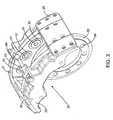
- a wheel rim 1 houses a disc brake system of the present invention.
- a circular rotor 5 is mounted on a circular rotor carrier 6 by bolts 7 (only one labeled).
- the rotor carrier 6 is in turn is mounted on a planetary wheel hub 15 by means of engaging splines on the rotor carrier 6 and the wheel hub 15.
- the wheel hub 15 is bolted to the wheel rim 1 with bolts 16 (only one labeled).
- An axle (not shown) is seated and held in wheel hub 15 at axle hub 17.
- the rotor is disposed between a first calliper half 21 and a second calliper half 22 of a split calliper design.
- the first calliper half 21 is integrally formed with a mounting ring 23 which is bolted to a vehicle's suspension (not shown) with bolts 24 (only one labeled).
- the suspension would be on the right side of the drawing page given the orientation of Fig. 1 .
- the calliper halves 21,22 are joined together in spaced apart relation by two joiner plates, one of which is shown in Fig. 1 at 25.
- the joiner plate 25 has notches 31,32 to assist in holding the calliper halves together.
- Brake pads 41,42 mounted on the calliper halves are pushed against the rotor 5 by pistons 51, 52 in the calliper halves (only one piston per calliper half shown) in response to a signal from a vehicle operator.
- the pistons 51,52 are environmentally sealed with seals 53,54.
- Pressure lines 71,72 in calliper halves 21,22 respectively carry brake fluid to the pistons 51,52 respectively.
- First "bleeding" port 61 is a valve that permits air to escape from the first calliper half 21 when the brakes are “bled”.
- the first calliper 21 integrally formed with the mounting ring 23 is more clearly depicted in a rear perspective view.
- the first calliper half is shaped to direct pressure points towards the joiner plates (not shown) which are attached to the calliper half 21 at surfaces 57,58.
- the surfaces 57,58 are two sets of bolt holes so that the joiner plates can be attached at two different positions. Choice of attachment position depends on the thickness of the rotor.
- the mounting ring 23 has 10 bolt holes 59 (only one labeled) for bolting the mounting ring on to the suspension.
- the central aperture 60 provides room for the axle (not shown) to rotate freely.
- First "bleeding" port 61 is shown on the first calliper half 21.
- a depression 63 provides a place for a cross rod (not shown) to be bolted to the calliper half.
- the cross rod may be used to help support the brake pads (not shown).
- the second calliper half is similar in shape and construction to the first calliper half except that the second calliper half does not have an integrally formed mounting ring.
- a calliper 20 is shown assembled in isolation.
- the first calliper half 21 and the second calliper half 22 are joined together in spaced apart relation by joiner plates 25,26.
- the joiner plates are well positioned to help scrape dirt and the like from the inside of the wheel rim top protect the workings of the brake system.
- the first calliper half 21 is shown with integrally formed mounting ring 23 having bolt holes 59 for bolting the calliper 20 to the suspension of the vehicle.
- the first calliper half has three pistons 51 sealed with environmental seals 53 for pushing against the brake pad (not shown).
- the second calliper half 22 has a similar set of three pistons and seals (not shown).
- a cross rod 65 is bolted to the calliper halves to provide help in supporting the brake pads.
- the second calliper half 22 is depicted with a fluid port 62 for allowing brake fluid to enter the internal pressure lines in the calliper half 22.
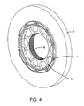
- Fig. 4 the rotor 5 mounted to the rotor carrier 6 by 10 bolts 7 (only one labeled) is shown in isolation.
- the rotor carrier has a smaller diameter than the rotor.
- the rotor and rotor carrier are mounted together concentrically.
- the rotor carrier has a spline 8 machined into an inner surface of the rotor carrier, the inner surface defining a central aperture in the rotor carrier.
- the spline 8 is machined to cooperate with a corresponding spline of the wheel hub (not shown), which will be described in more detail with reference to Figs. 6 and 7 .
- Fig. 5 the calliper of Fig. 3 is shown in combination with the rotor of Fig. 4 in reverse orientation with respect to Fig. 3 .
- the rotor 5 is disposed between the first calliper half 21 and the second calliper half 22.
- the first calliper half is integrally formed with mounting ring 23 and bolted to the suspension (not shown), now on the left side of the drawing sheet, through bolt holes 59 (only one labeled).
- the rotor 5 is bolted to the rotor carrier 6 by bolts 7 (only one labeled).
- the central aperture of the rotor carrier lines up concentrically with the aperture 60 of the mounting ring 23 to provide room for the axle (not shown) to protrude and rotate.
- the rotor carrier 6 is shown with spline 8.
- Joiner plates 25,26 join the calliper halves 21,22.
- Brake pads 41,42 are mounted on the calliper halves 21,22 and slidably mounted on the cross rod 65 next to the rotor 5.
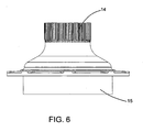
- the planetary wheel hub 15 has a spline 14 machined therein.
- the spline 14 of the wheel hub and the spline of the carrier rotor (not shown) are machined to fit together.
- the spline 14 of the wheel hub is seated in the spline of the rotor carrier so that the two splines intermesh and torque from the wheel hub generated by the rotating axle is transmitted to the rotor carrier to rotate the rotor with the axle.
- the wheel hub 15 is bolted to the wheel rim (not shown) through bolt holes, 13 (only one labeled) which receive the bolts 16 (see Fig. 1 ).
- FIG. 8 an exploded view of the brake system is shown in relation to a wheel station 80 comprising a suspension element 81 and an axle 82.
- the mounting ring 23 is bolted to the suspension element 81 through bolt holes 59 (only one labeled) on the mounting ring and bolt holes 83 (only one labeled) on the suspension element 81.
- the axle 82 protrudes the aperture 60 in the mounting ring and through the central aperture of the rotor carrier 6.
- the axle is seated in the axle hub of the wheel hub 15.
- the mounting ring 23 is integrally formed with the first calliper half 21 which has three pistons 51 (only one labeled) and a brake pad 41.
- the first calliper half 21 is joined to the second calliper half 22 by joiner plates 25,26 which are bolted to the calliper halves with bolts 90 (only one labeled).
- the spline 8 of the rotor carrier 6 is intermeshed with the spline 14 of the wheel hub 15.
- the rotor 5 is disposed between the calliper halves 21,22.
Landscapes
- Engineering & Computer Science (AREA)
- General Engineering & Computer Science (AREA)
- Mechanical Engineering (AREA)
- Braking Arrangements (AREA)
Claims (35)
- Etrier (20) pour un système de frein à disque d'un véhicule ayant un essieu, comprenant :- un premier demi-étrier (21) ;- un second demi-étrier (22) formé de façon séparée du premier demi-étrier (21) ;- une ou plusieurs platines de liaison (25, 26) attachées aux demi-étriers (21, 22) ;- chaque demi-étrier (21, 22) ayant des moyens de retenue de plaquettes de frein ; et- chaque demi-étrier (21, 22) ayant des moyens permettant l'engagement des plaquettes de frein contre un rotor de frein du système de frein à disque sous l'effet d'un signal provenant d'un opérateur du véhicule,caractérisé en ce que- le premier demi-étrier (21) est solidaire d'une platine de montage (23) permettant de monter l'étrier (20) de manière fixe sur le véhicule, à une position proximale par rapport à l'essieu ; et en ce que- la ou les platines de liaison (25, 26) sont attachées de manière fixe et démontable aux demi-étriers (21, 22), à différentes positions sur la ou les platines de liaison (25, 26), pour permettre la fixation des demi-étriers (21, 22) à une pluralité de distances d'espacement afin d'autoriser la rotation de rotors de frein de différentes épaisseurs entre les demi-étriers (21, 22).
- Etrier (20) selon la revendication 1, dans lequel la pluralité de distances d'espacement est au nombre de deux distances d'espacement.
- Etrier (20) selon la revendication 1 ou 2, dans lequel les demi-étriers (21, 22) ont des hauteurs définissant une hauteur de l'étrier (20), et la ou les platines de liaison (25, 26) ont des épaisseurs qui n'augmentent pas la hauteur de l'étrier (20).
- Etrier (20) selon l'une quelconque des revendications 1 à 3, dans lequel la ou les platines de liaison (25, 26) ont des encoches dans lesquelles sont logés les demi-étriers (21, 22), et la ou les platines de liaison (25, 26) sont attachées aux demi-étriers (21, 22) par des boulons.
- Etrier (20) selon l'une quelconque des revendications 1 à 4, dans lequel la ou les platines de liaison (25, 26) sont au nombre de deux platines de liaison.
- Etrier (20) selon l'une quelconque des revendications 1 à 5, dans lequel la platine de montage (23) comprend des trous de boulon (59) pour permettre le boulonnage de la platine de montage sur le véhicule.
- Etrier (20) selon l'une quelconque des revendications 1 à 6, dans lequel la platine de montage (23) comprend une bague ayant une ouverture centrale (60) pour laisser à l'essieu la place de tourner librement.
- Etrier (20) selon l'une quelconque des revendications 1 à 7, dans lequel les moyens de retenue des plaquettes de frein comprennent un déport interne dans chacun des demi-étriers (21, 22), une tige transversale entre les demi-étriers (21, 22), ou un déport interne dans chacun des demi-étriers (21, 22) ainsi qu'une tige transversale entre les demi-étriers (21, 22).
- Etrier (20) selon l'une quelconque des revendications 1 à 8, dans lequel les moyens pour l'engagement des plaquettes de frein contre le rotor comprennent un ou plusieurs pistons (51, 52).
- Etrier (20) selon la revendication 9, dans lequel le ou les pistons (51, 52) sont logés dans un ou plusieurs orifices pour pistons obturés de façon étanche vis-à-vis de l'environnement.
- Etrier (20) selon la revendication 9 ou 10, dans lequel le ou les pistons (51, 52) sont actionnés de manière hydraulique.
- Etrier (20) selon l'une quelconque des revendications 9 à 11, dans lequel le ou les pistons (51, 52) comprennent une céramique, ou une combinaison de céramique et d'aluminium.
- Système de frein à disque pour un véhicule ayant un essieu, comprenant :- un étrier (20) selon la revendication 1,- un rotor de frein (5) disposé entre le premier demi-étrier (21) et le second demi-étrier (22), le rotor de frein (5) pouvant tourner entre les demi-étriers (21, 22), le rotor de frein (5) étant monté sur l'essieu du véhicule, le rotor de frein (5) tournant sous l'effet de la rotation de l'essieu ; et- des plaquettes de frein (41, 42) montées sur chaque demi-étrier (21, 22), chaque demi-étrier (21, 22) ayant des moyens permettant l'engagement des plaquettes de frein (41, 42) contre le rotor (5) sous l'effet d'un signal provenant d'un opérateur du véhicule.
- Système de frein selon la revendication 13, dans lequel le rotor de frein (5) est monté sur un support de rotor (6), le support de rotor (6) est monté sur un carter de moyeu de roue, et le carter de moyeu de roue est monté sur l'essieu.
- Système de frein selon la revendication 14, dans lequel le support de rotor (6) est monté sur le carter de moyeu de roue par un accouplement par cannelures conjuguées.
- Système de frein selon l'une quelconque des revendications 13 à 15, dans lequel la pluralité de distances d'espacement est au nombre de deux distances d'espacement.
- Système de frein selon l'une quelconque des revendications 13 à 16, dans lequel les demi-étriers (21, 22) ont des hauteurs définissant une hauteur du système de frein, et la ou les platines de liaison (25, 26) ont des épaisseurs qui n'augmentent pas la hauteur du système de frein.
- Système de frein selon l'une quelconque des revendications 13 à 17, dans lequel la ou les platines de liaison (25, 26) ont des encoches dans lesquelles sont logés les demi-étriers (21, 22), et la ou les platines de liaison (25, 26) sont attachées aux demi-étriers (21, 22) par des boulons.
- Système de frein selon l'une quelconque des revendications 13 à 18, dans lequel la ou les platines de liaison (25, 26) sont au nombre de deux platines de liaison.
- Système de frein selon l'une quelconque des revendications 13 à 19, dans lequel la platine de montage (23) comprend des trous de boulon (59) pour permettre le boulonnage de la platine de montage sur le véhicule.
- Système de frein selon l'une quelconque des revendications 13 à 20, dans lequel la platine de montage (23) comprend une bague ayant une ouverture centrale (60) pour laisser à l'essieu la place de tourner librement.
- Système de frein selon l'une quelconque des revendications 13 à 21, dans lequel les demi-étriers (21, 22) comprennent un déport interne dans chacun des demi-étriers (21, 22), une tige transversale entre les demi-étriers (21, 22), ou un déport interne dans chacun des demi-étriers (21, 22) ainsi qu'une tige transversale entre les demi-étriers (21, 22), pour retenir les plaquettes de frein (41, 42) sur les demi-étriers (21, 22).
- Système de frein selon l'une quelconque des revendications 13 à 22, dans lequel les moyens pour l'engagement des plaquettes de frein (41, 42) contre le rotor (5) comprennent un ou plusieurs pistons (51, 52).
- Système de frein selon la revendication 23, dans lequel le ou les pistons (51, 52) sont logés dans un ou plusieurs orifices pour pistons obturés de façon étanche vis-à-vis de l'environnement.
- Système de frein selon la revendication 23 ou 24, dans lequel le ou les pistons (51, 52) sont actionnés de manière hydraulique.
- Système de frein selon l'une quelconque des revendications 23 à 25, dans lequel le ou les pistons (51, 52) comprennent une céramique, ou une combinaison de céramique et d'aluminium.
- Système de frein selon l'une quelconque des revendications 13 à 26, dans lequel le rotor (5) comprend un matériau céramique renforcé de fibres de carbone.
- Utilisation d'un système de frein à disque tel que défini dans l'une quelconque des revendications 13 à 27 sur un véhicule motorisé.
- Utilisation selon la revendication 28, dans laquelle le véhicule motorisé est une automobile, un camion, un bus ou un véhicule militaire.
- Utilisation selon la revendication 28, dans laquelle le véhicule motorisé est un véhicule blindé léger.
- Utilisation selon l'une quelconque des revendications 28 à 30, dans laquelle la platine de montage est montée sur un ensemble de suspension du véhicule.
- Utilisation selon l'une quelconque des revendications 28 à 31, dans laquelle le rotor est monté sur un carter de moyeu de roue planétaire du véhicule.
- Procédé de pose d'un système de freinage en adaptation sur un véhicule existant ayant un essieu, le procédé comprenant les étapes consistant à :(a) démonter un système de frein à tambour existant de sa position proximale par rapport à l'essieu du véhicule ;(b) monter un premier demi-étrier (21) sur le véhicule, à une position proximale par rapport à l'essieu, au moyen d'une platine de montage (23) solidaire du premier demi-étrier (21) ;(c) attacher de manière fixe et démontable un second demi-étrier (22) au premier demi-étrier (21) au moyen d'une ou plusieurs platines de liaison (25, 26), qui sont attachées de manière fixe et démontable aux demi-étriers (21, 22), à différentes positions sur la ou les platines de liaison (25, 26), de façon que les premier et second demi-étriers (21, 22) soient espacés en conséquence l'un par rapport à l'autre ;(d) monter un rotor de frein (5) sur un carter de moyeu de roue de telle sorte que le rotor (5) puisse tourner en association avec le carter de moyeu de roue ;(e) monter fixement le carter de moyeu de roue sur l'essieu de telle sorte que le rotor de frein (5) soit disposé entre les demi-étriers (21, 22), les demi-étriers (21, 22) portant des plaquettes de frein (41, 42) et ayant des moyens permettant l'engagement des plaquettes de frein (41, 42) contre le rotor (5) sous l'effet d'un signal provenant d'un opérateur du véhicule ; et(f) monter fixement une jante de roue sur le carter de moyeu de roue.
- Procédé selon la revendication 33, dans lequel le rotor de frein (5) est monté sur un support de rotor (6), et le support de rotor (6) est monté sur le carter de moyeu de roue par un accouplement par cannelures conjuguées.
- Procédé selon la revendication 33 ou 34, dans lequel le premier demi-étrier (21) est monté sur un ensemble de suspension du véhicule.
Applications Claiming Priority (2)
| Application Number | Priority Date | Filing Date | Title |
|---|---|---|---|
| CA2484405A CA2484405C (fr) | 2004-10-12 | 2004-10-12 | Frein a disque |
| PCT/CA2005/001552 WO2006039794A1 (fr) | 2004-10-12 | 2005-10-11 | Systeme de frein a disque |
Publications (3)
| Publication Number | Publication Date |
|---|---|
| EP1831579A1 EP1831579A1 (fr) | 2007-09-12 |
| EP1831579A4 EP1831579A4 (fr) | 2009-06-24 |
| EP1831579B1 true EP1831579B1 (fr) | 2010-12-29 |
Family
ID=36148004
Family Applications (1)
| Application Number | Title | Priority Date | Filing Date |
|---|---|---|---|
| EP05794885A Active EP1831579B1 (fr) | 2004-10-12 | 2005-10-11 | Systeme de frein a disque |
Country Status (8)
| Country | Link |
|---|---|
| US (1) | US8453804B2 (fr) |
| EP (1) | EP1831579B1 (fr) |
| AT (1) | ATE493594T1 (fr) |
| CA (1) | CA2484405C (fr) |
| DE (1) | DE602005025693D1 (fr) |
| DK (1) | DK1831579T3 (fr) |
| ES (1) | ES2358602T3 (fr) |
| WO (1) | WO2006039794A1 (fr) |
Families Citing this family (13)
| Publication number | Priority date | Publication date | Assignee | Title |
|---|---|---|---|---|
| DE102004050349B4 (de) * | 2004-10-15 | 2007-06-14 | Wabco Radbremsen Gmbh | Nutzfahrzeuge-Scheibenbremse |
| DE502006008102D1 (de) * | 2005-11-03 | 2010-11-25 | Knorr Bremse Systeme | Bremsbelaganordnung |
| US9676845B2 (en) | 2009-06-16 | 2017-06-13 | Hoffmann-La Roche, Inc. | Bispecific antigen binding proteins |
| DE102011056575A1 (de) * | 2011-12-19 | 2013-06-20 | Dr. Ing. H.C. F. Porsche Aktiengesellschaft | Kraftfahrzeugbremssystem |
| WO2013112158A1 (fr) * | 2012-01-26 | 2013-08-01 | Magna E-Car Systems Of America Inc. | Assemblage de roue de véhicule |
| USD784220S1 (en) * | 2015-08-17 | 2017-04-18 | Shandong Haoxin Machinery Co., Ltd. | Brake drum |
| CN112189101A (zh) * | 2018-05-23 | 2021-01-05 | 威伯科欧洲有限责任公司 | 制动器载体上的方向箭头 |
| CN110342381B (zh) * | 2019-06-17 | 2023-12-22 | 菱王电梯有限公司 | 块式制动内转子曳引机 |
| DE102019124441A1 (de) * | 2019-09-11 | 2021-03-11 | Zf Active Safety Gmbh | Bremssattel für eine Fahrzeugscheibenbremse |
| CN113521812B (zh) * | 2020-04-22 | 2022-12-27 | 宝武装备智能科技有限公司 | 一种行车式刮泥机刹车系统 |
| CN115596783A (zh) * | 2021-06-28 | 2023-01-13 | 比亚迪股份有限公司(Cn) | 制动器卡钳和具有其的车辆 |
| CN114561641B (zh) * | 2022-02-11 | 2023-11-03 | 上海壬丰复合材料有限公司 | 一种陶瓷增强铝基复合材料制动盘的表面摩擦处理方法 |
| CN114562526B (zh) * | 2022-03-01 | 2024-01-23 | 山东倍瑞恳新材料有限公司 | 一种便于拆卸更换的分体式轨道车辆制动盘 |
Family Cites Families (24)
| Publication number | Priority date | Publication date | Assignee | Title |
|---|---|---|---|---|
| US2356258A (en) * | 1942-07-22 | 1944-08-22 | Martin Philip | Motor vehicle brake |
| US4019611A (en) * | 1976-03-15 | 1977-04-26 | The Bendix Corporation | Disc brake |
| US4144953A (en) | 1977-05-09 | 1979-03-20 | Loffland Brothers Company | Rotary drive disc brake for drawworks |
| US4537289A (en) * | 1982-06-18 | 1985-08-27 | International Telephone And Telegraph Corporation | Dust boot for a disc-brake actuating cylinder-and-piston unit |
| US4535873A (en) * | 1983-08-15 | 1985-08-20 | Alston Industries, Inc. | Compact high performance disc brake |
| US4638894A (en) | 1985-05-30 | 1987-01-27 | Eaton Corporation | Caliper disc brake assembly |
| DE8633923U1 (de) * | 1986-12-18 | 1988-04-21 | Lucas Industries P.L.C., Birmingham, West Midlands | Betätigungsvorrichtung mit selbsttätiger Nachstellung für Bremsen, insbesondere von Schwerlastfahrzeugen |
| JP2781805B2 (ja) * | 1988-05-03 | 1998-07-30 | セラム―エング プロプライエタリテイ リミテッド | ブレーキユニット |
| DE4036272A1 (de) * | 1990-11-14 | 1992-05-21 | Perrot Bremse Gmbh Deutsche | Gleitsattel-scheibenbremse |
| DE4103894A1 (de) | 1991-02-08 | 1992-08-13 | Knorr Bremse Ag | Scheibenbremse fuer schienenfahrzeuge |
| US5316110A (en) | 1992-03-24 | 1994-05-31 | Null Robert L | Trailer brake system with release apparatus |
| DE4324988A1 (de) | 1993-07-26 | 1995-02-02 | Teves Gmbh Alfred | Teilbelag-Scheibenbremse mit einem mehrteiligen Festsattel aus unterschiedlichen Werkstoffen |
| US5538105A (en) * | 1995-03-07 | 1996-07-23 | Dayton Walther Corporation | Brake shoe hold down clip for disc brake assembly |
| DE19530407A1 (de) | 1995-08-18 | 1997-02-20 | Teves Gmbh Alfred | Festsattel - Teilbelagscheibenbremse für Kraftfahrzeuge |
| US6019199A (en) * | 1997-05-19 | 2000-02-01 | Power Transmission Technology, Inc. | Hydraulic caliper disk brake for steel mill cranes |
| DE19727586C2 (de) * | 1997-06-28 | 2002-10-24 | Daimler Chrysler Ag | Bremseinheit aus Bremsscheibe und Bremsbelag |
| US6068091A (en) * | 1997-12-24 | 2000-05-30 | Finley; George | Externally mounted bracket system for disc brakes |
| JP3901329B2 (ja) | 1998-02-10 | 2007-04-04 | 日清紡績株式会社 | ディスクブレーキ装置 |
| GB2340560A (en) * | 1998-08-15 | 2000-02-23 | T & N Technology Ltd | Disc brake |
| US6186291B1 (en) | 1998-09-09 | 2001-02-13 | James F. Barnard | Brake system for heavy equipment |
| US6302243B1 (en) * | 1999-10-29 | 2001-10-16 | Stoptech Technologies Llc | Stiffening bracket for brake calipers |
| FR2833325B1 (fr) * | 2001-12-10 | 2005-05-20 | Beringer Sa | Dispositif de freinage d'un vehicule |
| US6945367B1 (en) * | 2004-05-24 | 2005-09-20 | Robert Bosch Gmbh | Rotor and exciter ring |
| US7438161B2 (en) * | 2004-09-17 | 2008-10-21 | Performance Friction Corporation | Quick release removable bridge caliper |
-
2004
- 2004-10-12 CA CA2484405A patent/CA2484405C/fr not_active Expired - Lifetime
-
2005
- 2005-10-11 ES ES05794885T patent/ES2358602T3/es active Active
- 2005-10-11 AT AT05794885T patent/ATE493594T1/de active
- 2005-10-11 DK DK05794885.3T patent/DK1831579T3/da active
- 2005-10-11 DE DE602005025693T patent/DE602005025693D1/de active Active
- 2005-10-11 US US11/577,010 patent/US8453804B2/en active Active
- 2005-10-11 WO PCT/CA2005/001552 patent/WO2006039794A1/fr active Application Filing
- 2005-10-11 EP EP05794885A patent/EP1831579B1/fr active Active
Also Published As
| Publication number | Publication date |
|---|---|
| CA2484405C (fr) | 2011-03-22 |
| CA2484405A1 (fr) | 2006-04-12 |
| EP1831579A1 (fr) | 2007-09-12 |
| US20080093180A1 (en) | 2008-04-24 |
| WO2006039794A1 (fr) | 2006-04-20 |
| US8453804B2 (en) | 2013-06-04 |
| ATE493594T1 (de) | 2011-01-15 |
| DK1831579T3 (da) | 2011-04-04 |
| EP1831579A4 (fr) | 2009-06-24 |
| DE602005025693D1 (de) | 2011-02-10 |
| ES2358602T3 (es) | 2011-05-12 |
Similar Documents
| Publication | Publication Date | Title |
|---|---|---|
| EP1831579B1 (fr) | Systeme de frein a disque | |
| JP4149515B2 (ja) | ディスクブレーキ用ディスク―ハブ接続装置 | |
| JP5207691B2 (ja) | ブレーキキャリア | |
| EP1610025B1 (fr) | Procédé pour commander un ensemble de frein à disque. | |
| US20060086579A1 (en) | Disc brake rotor | |
| US8613345B1 (en) | Quick change combination wheel and brake assembly | |
| RU2565156C2 (ru) | Облегченный составной блок пружинного тормозного привода | |
| US4509619A (en) | Shoe mounted disc brake caliper and shoe support structure | |
| CA2559737C (fr) | Frein a disque exterieur a l'enveloppe de frein | |
| US20100193303A1 (en) | Brake spider weldment and anchor pin assembly | |
| GB2085101A (en) | Light weight disc brake caliper | |
| CA2195063C (fr) | Ensemble support de freins | |
| CA1048947A (fr) | Jante pour roues munies de commandes a couple de freinage | |
| WO2015196037A1 (fr) | Rotor de frein à diamètre réduit pour véhicules utilitaires lourds | |
| CN209833598U (zh) | 驻车制动系统和车辆 | |
| US20200171879A1 (en) | Wheel disc brake assembly | |
| CN220470509U (zh) | 用于轮毂驱动装置的制动设备 | |
| CN217002806U (zh) | 制动盘 | |
| CA2386134A1 (fr) | Frein de camion de chantier et fusee de roue comprenant un joint cannele | |
| US20120279813A1 (en) | Wheel assembly | |
| WO1999013239A1 (fr) | Ensemble frein pour vehicule routier | |
| CN109849871B (zh) | 驻车制动系统和车辆 | |
| CN110345182B (zh) | 一种应用于电动轮驱动车辆的驻车制动装置 | |
| CN111301367B (zh) | 一种用于碳纤维复合材料制动盘的双向浮动固定结构 | |
| WO2005064189A1 (fr) | Etrier modulaire a monture flexible |
Legal Events
| Date | Code | Title | Description |
|---|---|---|---|
| PUAI | Public reference made under article 153(3) epc to a published international application that has entered the european phase |
Free format text: ORIGINAL CODE: 0009012 |
|
| 17P | Request for examination filed |
Effective date: 20070514 |
|
| AK | Designated contracting states |
Kind code of ref document: A1 Designated state(s): AT BE BG CH CY CZ DE DK EE ES FI FR GB GR HU IE IS IT LI LT LU LV MC NL PL PT RO SE SI SK TR |
|
| DAX | Request for extension of the european patent (deleted) | ||
| A4 | Supplementary search report drawn up and despatched |
Effective date: 20090527 |
|
| 17Q | First examination report despatched |
Effective date: 20090720 |
|
| GRAP | Despatch of communication of intention to grant a patent |
Free format text: ORIGINAL CODE: EPIDOSNIGR1 |
|
| GRAS | Grant fee paid |
Free format text: ORIGINAL CODE: EPIDOSNIGR3 |
|
| GRAA | (expected) grant |
Free format text: ORIGINAL CODE: 0009210 |
|
| AK | Designated contracting states |
Kind code of ref document: B1 Designated state(s): AT BE BG CH CY CZ DE DK EE ES FI FR GB GR HU IE IS IT LI LT LU LV MC NL PL PT RO SE SI SK TR |
|
| REG | Reference to a national code |
Ref country code: GB Ref legal event code: FG4D |
|
| REG | Reference to a national code |
Ref country code: CH Ref legal event code: EP |
|
| REG | Reference to a national code |
Ref country code: IE Ref legal event code: FG4D |
|
| REF | Corresponds to: |
Ref document number: 602005025693 Country of ref document: DE Date of ref document: 20110210 Kind code of ref document: P |
|
| REG | Reference to a national code |
Ref country code: DE Ref legal event code: R096 Ref document number: 602005025693 Country of ref document: DE Effective date: 20110210 |
|
| REG | Reference to a national code |
Ref country code: DK Ref legal event code: T3 |
|
| REG | Reference to a national code |
Ref country code: SE Ref legal event code: TRGR |
|
| REG | Reference to a national code |
Ref country code: NL Ref legal event code: T3 |
|
| PG25 | Lapsed in a contracting state [announced via postgrant information from national office to epo] |
Ref country code: LT Free format text: LAPSE BECAUSE OF FAILURE TO SUBMIT A TRANSLATION OF THE DESCRIPTION OR TO PAY THE FEE WITHIN THE PRESCRIBED TIME-LIMIT Effective date: 20101229 |
|
| REG | Reference to a national code |
Ref country code: ES Ref legal event code: FG2A Ref document number: 2358602 Country of ref document: ES Kind code of ref document: T3 Effective date: 20110429 |
|
| LTIE | Lt: invalidation of european patent or patent extension |
Effective date: 20101229 |
|
| PG25 | Lapsed in a contracting state [announced via postgrant information from national office to epo] |
Ref country code: FI Free format text: LAPSE BECAUSE OF FAILURE TO SUBMIT A TRANSLATION OF THE DESCRIPTION OR TO PAY THE FEE WITHIN THE PRESCRIBED TIME-LIMIT Effective date: 20101229 Ref country code: LV Free format text: LAPSE BECAUSE OF FAILURE TO SUBMIT A TRANSLATION OF THE DESCRIPTION OR TO PAY THE FEE WITHIN THE PRESCRIBED TIME-LIMIT Effective date: 20101229 Ref country code: SI Free format text: LAPSE BECAUSE OF FAILURE TO SUBMIT A TRANSLATION OF THE DESCRIPTION OR TO PAY THE FEE WITHIN THE PRESCRIBED TIME-LIMIT Effective date: 20101229 Ref country code: BG Free format text: LAPSE BECAUSE OF FAILURE TO SUBMIT A TRANSLATION OF THE DESCRIPTION OR TO PAY THE FEE WITHIN THE PRESCRIBED TIME-LIMIT Effective date: 20110329 Ref country code: CY Free format text: LAPSE BECAUSE OF FAILURE TO SUBMIT A TRANSLATION OF THE DESCRIPTION OR TO PAY THE FEE WITHIN THE PRESCRIBED TIME-LIMIT Effective date: 20101229 |
|
| RAP2 | Party data changed (patent owner data changed or rights of a patent transferred) |
Owner name: 2040422 ONTARIO INC. |
|
| PG25 | Lapsed in a contracting state [announced via postgrant information from national office to epo] |
Ref country code: GR Free format text: LAPSE BECAUSE OF FAILURE TO SUBMIT A TRANSLATION OF THE DESCRIPTION OR TO PAY THE FEE WITHIN THE PRESCRIBED TIME-LIMIT Effective date: 20110330 Ref country code: IS Free format text: LAPSE BECAUSE OF FAILURE TO SUBMIT A TRANSLATION OF THE DESCRIPTION OR TO PAY THE FEE WITHIN THE PRESCRIBED TIME-LIMIT Effective date: 20110429 Ref country code: EE Free format text: LAPSE BECAUSE OF FAILURE TO SUBMIT A TRANSLATION OF THE DESCRIPTION OR TO PAY THE FEE WITHIN THE PRESCRIBED TIME-LIMIT Effective date: 20101229 Ref country code: PT Free format text: LAPSE BECAUSE OF FAILURE TO SUBMIT A TRANSLATION OF THE DESCRIPTION OR TO PAY THE FEE WITHIN THE PRESCRIBED TIME-LIMIT Effective date: 20110429 |
|
| PG25 | Lapsed in a contracting state [announced via postgrant information from national office to epo] |
Ref country code: SK Free format text: LAPSE BECAUSE OF FAILURE TO SUBMIT A TRANSLATION OF THE DESCRIPTION OR TO PAY THE FEE WITHIN THE PRESCRIBED TIME-LIMIT Effective date: 20101229 Ref country code: PL Free format text: LAPSE BECAUSE OF FAILURE TO SUBMIT A TRANSLATION OF THE DESCRIPTION OR TO PAY THE FEE WITHIN THE PRESCRIBED TIME-LIMIT Effective date: 20101229 Ref country code: RO Free format text: LAPSE BECAUSE OF FAILURE TO SUBMIT A TRANSLATION OF THE DESCRIPTION OR TO PAY THE FEE WITHIN THE PRESCRIBED TIME-LIMIT Effective date: 20101229 |
|
| PLBE | No opposition filed within time limit |
Free format text: ORIGINAL CODE: 0009261 |
|
| STAA | Information on the status of an ep patent application or granted ep patent |
Free format text: STATUS: NO OPPOSITION FILED WITHIN TIME LIMIT |
|
| 26N | No opposition filed |
Effective date: 20110930 |
|
| REG | Reference to a national code |
Ref country code: DE Ref legal event code: R081 Ref document number: 602005025693 Country of ref document: DE Owner name: 2040422 ONTARIO INC., CA Free format text: FORMER OWNER: 2040422 ONTARIO INC., LONDON, ONTARIO, CA Effective date: 20111117 Ref country code: DE Ref legal event code: R082 Ref document number: 602005025693 Country of ref document: DE Representative=s name: ZEUNER SUMMERER STUETZ PATENT- UND RECHTSANWAL, DE Effective date: 20111117 Ref country code: DE Ref legal event code: R081 Ref document number: 602005025693 Country of ref document: DE Owner name: 2040422 ONTARIO INC., DORCHESTER, CA Free format text: FORMER OWNER: 2040422 ONTARIO INC., LONDON, ONTARIO, CA Effective date: 20111117 |
|
| REG | Reference to a national code |
Ref country code: DE Ref legal event code: R097 Ref document number: 602005025693 Country of ref document: DE Effective date: 20110930 |
|
| PG25 | Lapsed in a contracting state [announced via postgrant information from national office to epo] |
Ref country code: IT Free format text: LAPSE BECAUSE OF FAILURE TO SUBMIT A TRANSLATION OF THE DESCRIPTION OR TO PAY THE FEE WITHIN THE PRESCRIBED TIME-LIMIT Effective date: 20101229 Ref country code: MC Free format text: LAPSE BECAUSE OF NON-PAYMENT OF DUE FEES Effective date: 20111031 |
|
| REG | Reference to a national code |
Ref country code: CH Ref legal event code: PL |
|
| PG25 | Lapsed in a contracting state [announced via postgrant information from national office to epo] |
Ref country code: LI Free format text: LAPSE BECAUSE OF NON-PAYMENT OF DUE FEES Effective date: 20111031 Ref country code: CH Free format text: LAPSE BECAUSE OF NON-PAYMENT OF DUE FEES Effective date: 20111031 |
|
| REG | Reference to a national code |
Ref country code: IE Ref legal event code: MM4A |
|
| PG25 | Lapsed in a contracting state [announced via postgrant information from national office to epo] |
Ref country code: IE Free format text: LAPSE BECAUSE OF NON-PAYMENT OF DUE FEES Effective date: 20111011 |
|
| PG25 | Lapsed in a contracting state [announced via postgrant information from national office to epo] |
Ref country code: LU Free format text: LAPSE BECAUSE OF NON-PAYMENT OF DUE FEES Effective date: 20111011 |
|
| PG25 | Lapsed in a contracting state [announced via postgrant information from national office to epo] |
Ref country code: TR Free format text: LAPSE BECAUSE OF FAILURE TO SUBMIT A TRANSLATION OF THE DESCRIPTION OR TO PAY THE FEE WITHIN THE PRESCRIBED TIME-LIMIT Effective date: 20101229 |
|
| PG25 | Lapsed in a contracting state [announced via postgrant information from national office to epo] |
Ref country code: HU Free format text: LAPSE BECAUSE OF FAILURE TO SUBMIT A TRANSLATION OF THE DESCRIPTION OR TO PAY THE FEE WITHIN THE PRESCRIBED TIME-LIMIT Effective date: 20101229 |
|
| REG | Reference to a national code |
Ref country code: FR Ref legal event code: PLFP Year of fee payment: 11 |
|
| REG | Reference to a national code |
Ref country code: FR Ref legal event code: PLFP Year of fee payment: 12 |
|
| REG | Reference to a national code |
Ref country code: FR Ref legal event code: PLFP Year of fee payment: 13 |
|
| REG | Reference to a national code |
Ref country code: FR Ref legal event code: PLFP Year of fee payment: 14 |
|
| PGFP | Annual fee paid to national office [announced via postgrant information from national office to epo] |
Ref country code: NL Payment date: 20231019 Year of fee payment: 19 |
|
| PGFP | Annual fee paid to national office [announced via postgrant information from national office to epo] |
Ref country code: GB Payment date: 20231020 Year of fee payment: 19 |
|
| PGFP | Annual fee paid to national office [announced via postgrant information from national office to epo] |
Ref country code: ES Payment date: 20231222 Year of fee payment: 19 |
|
| PGFP | Annual fee paid to national office [announced via postgrant information from national office to epo] |
Ref country code: SE Payment date: 20231019 Year of fee payment: 19 Ref country code: FR Payment date: 20231023 Year of fee payment: 19 Ref country code: DK Payment date: 20231024 Year of fee payment: 19 Ref country code: DE Payment date: 20231020 Year of fee payment: 19 Ref country code: CZ Payment date: 20231004 Year of fee payment: 19 Ref country code: AT Payment date: 20231020 Year of fee payment: 19 |
|
| PGFP | Annual fee paid to national office [announced via postgrant information from national office to epo] |
Ref country code: BE Payment date: 20231019 Year of fee payment: 19 |