EP1824577B1 - Rotary valve assembly for fluid filtration system - Google Patents
Rotary valve assembly for fluid filtration system Download PDFInfo
- Publication number
- EP1824577B1 EP1824577B1 EP05815356A EP05815356A EP1824577B1 EP 1824577 B1 EP1824577 B1 EP 1824577B1 EP 05815356 A EP05815356 A EP 05815356A EP 05815356 A EP05815356 A EP 05815356A EP 1824577 B1 EP1824577 B1 EP 1824577B1
- Authority
- EP
- European Patent Office
- Prior art keywords
- valve
- valve member
- inlet
- outlet
- filter
- Prior art date
- Legal status (The legal status is an assumption and is not a legal conclusion. Google has not performed a legal analysis and makes no representation as to the accuracy of the status listed.)
- Expired - Lifetime
Links
Images


Classifications
-
- B—PERFORMING OPERATIONS; TRANSPORTING
- B01—PHYSICAL OR CHEMICAL PROCESSES OR APPARATUS IN GENERAL
- B01D—SEPARATION
- B01D35/00—Filtering devices having features not specifically covered by groups B01D24/00 - B01D33/00, or for applications not specifically covered by groups B01D24/00 - B01D33/00; Auxiliary devices for filtration; Filter housing constructions
- B01D35/14—Safety devices specially adapted for filtration; Devices for indicating clogging
- B01D35/153—Anti-leakage or anti-return valves
-
- B—PERFORMING OPERATIONS; TRANSPORTING
- B01—PHYSICAL OR CHEMICAL PROCESSES OR APPARATUS IN GENERAL
- B01D—SEPARATION
- B01D27/00—Cartridge filters of the throw-away type
- B01D27/08—Construction of the casing
-
- B—PERFORMING OPERATIONS; TRANSPORTING
- B01—PHYSICAL OR CHEMICAL PROCESSES OR APPARATUS IN GENERAL
- B01D—SEPARATION
- B01D27/00—Cartridge filters of the throw-away type
- B01D27/10—Safety devices, e.g. by-passes
- B01D27/106—Anti-leakage or anti-return valves
-
- B—PERFORMING OPERATIONS; TRANSPORTING
- B01—PHYSICAL OR CHEMICAL PROCESSES OR APPARATUS IN GENERAL
- B01D—SEPARATION
- B01D35/00—Filtering devices having features not specifically covered by groups B01D24/00 - B01D33/00, or for applications not specifically covered by groups B01D24/00 - B01D33/00; Auxiliary devices for filtration; Filter housing constructions
- B01D35/14—Safety devices specially adapted for filtration; Devices for indicating clogging
- B01D35/147—Bypass or safety valves
-
- B—PERFORMING OPERATIONS; TRANSPORTING
- B01—PHYSICAL OR CHEMICAL PROCESSES OR APPARATUS IN GENERAL
- B01D—SEPARATION
- B01D2201/00—Details relating to filtering apparatus
- B01D2201/16—Valves
- B01D2201/165—Multi-way valves
-
- B—PERFORMING OPERATIONS; TRANSPORTING
- B01—PHYSICAL OR CHEMICAL PROCESSES OR APPARATUS IN GENERAL
- B01D—SEPARATION
- B01D2201/00—Details relating to filtering apparatus
- B01D2201/30—Filter housing constructions
- B01D2201/301—Details of removable closures, lids, caps, filter heads
- B01D2201/302—Details of removable closures, lids, caps, filter heads having inlet or outlet ports
-
- B—PERFORMING OPERATIONS; TRANSPORTING
- B01—PHYSICAL OR CHEMICAL PROCESSES OR APPARATUS IN GENERAL
- B01D—SEPARATION
- B01D2201/00—Details relating to filtering apparatus
- B01D2201/40—Special measures for connecting different parts of the filter
- B01D2201/4046—Means for avoiding false mounting of different parts
Definitions
- the subject disclosure relates to fluid filtration devices, and more particularly, to a filter assembly having a keyed lockout system to ensure replacement filter cartridge compatibility, and to a rotary valve assembly configured to operate in a filter mode when the filter cartridge is installed in the system and a by-pass mode when the filter cartridge is removed from the system.
- the replaceable filters employed in commercial and consumer appliances are manufactured in accordance with particular design specifications and performance parameters provided by the appliance manufacturer.
- the filter media used in such filters consists of a proprietary material or is manufactured using a proprietary process.
- appliance manufactures often recommend that replacement cartridges be purchased from the original equipment provider so as to ensure the integrity and proper operation of the filtering system.
- the invention provides a valve assembly for use in conjunction with a replaceable filter cartridge, as defined by the appended claims.
- the filter assembly comprises a cartridge member, which includes a body portion for enclosing filter media and a neck portion depending therefrom.
- the neck portion of the cartridge includes at least one inlet port for directing unfiltered fluid into the body portion and at least one outlet port for directing filtered fluid out of the body portion.
- the neck also has at least two lugs depending radially outwardly therefrom, wherein at least one lug defines a keyed engagement surface, a leading inclined cam surface and a trailing inclined cam surface.
- the keyed engagement surface is on an axially facing surface of the at least one lug.
- the neck portion of the cartridge member includes first and second axially facing surfaces.
- the first axially facing surface has at least one inlet port formed therein and the second axially facing surface has at least one outlet port formed therein.
- each lug defines a keyed engagement surface, a leading inclined cam surface and a trailing inclined cam surface. Still further, it is envisioned that the keyed engagement surface defined on each lug of the cartridge member is substantially similar. Alternatively, the keyed engagement surface defined on each lug of the cartridge member can be different.
- the representative filter assembly may further include a head member which defines an axial chamber and includes inlet and outlet passages that communicate with the chamber.
- a valve member is rotatably disposed within the axial chamber of the head member and defines an axial cavity for receiving the neck portion of the cartridge member to facilitate communication between the inlet and outlet passages of the head member and the inlet and outlet ports of the neck portion.
- the cavity formed in the valve member defines at least one reception slot, which includes a surface for mating with the keyed engagement surface formed on the lug(s).
- the reception slot(s) further defines at least one inclined surface for interacting with the trailing inclined cam surface formed on the lug(s) to facilitate engagement and/or disengagement of the cartridge member with the axial cavity of the valve member.
- the representative filter assembly may further include a support member which is disposed between the head member and the cartridge member and includes an aperture for receiving the neck portion of the cartridge member.
- the aperture has an inner surface that defines at least two cam ramps for interacting with the leading inclined cam surface formed on the lug(s) to facilitate engagement of the lug(s) of the cartridge member with the support member.
- the neck portion of the cartridge member has a pair of diametrically opposed lugs.
- the neck portion of the cartridge member has three circumferentially spaced apart lugs.
- the neck portion of the cartridge member has first and second pairs of diametrically opposed lugs, wherein the first pair of lugs is disposed at a first height on the neck portion and the second pair of lugs is disposed at a second height on the neck portion.
- the present disclosure is also directed to a representative filter cartridge, which includes a body portion and a neck portion.
- the body portion of the cartridge encloses filter media for filtering a fluid, which is passed therethrough.
- the neck portion communicates with the body portion and includes an inlet port for directing unfiltered fluid into the body portion and at least one outlet port for directing filtered fluid out of the body portion.
- the neck portion presently preferably, has at least two lugs, which depend radially outwardly therefrom, wherein at least one lug defines a keyed engagement surface, a leading inclined cam surface and a trailing inclined cam surface.
- the keyed engagement surface enables the cartridge to mate with a compatible reception assembly and the trailing inclined cam surface facilitating the mating therewith.
- each lug defines a keyed engagement surface, a leading inclined cam surface and a trailing inclined cam surface. Still further, it is envisioned that the keyed engagement surfaces defined on each lug of the cartridge member can be substantially similar or alternatively, they can be different.
- the neck portion of the cartridge member has a pair of diametrically opposed lugs.
- the neck portion of the cartridge member has three circumferentially spaced apart lugs.
- the neck portion of the cartridge member has first and second pairs of diametrically opposed lugs, wherein the first pair of lugs is disposed at a first height on the neck portion and the second pair of lugs is disposed at a second height on the neck portion.
- the present disclosure is also directed to a filter cartridge, which includes a body portion for enclosing filter media for filtering a fluid and a neck portion which communicates with the body portion.
- the neck portion includes at least one axial inlet port for directing unfiltered fluid into the body portion, at least one axial outlet port for directing filtered fluid out of the body portion and a neck portion having at least two lugs depending radially outwardly therefrom.
- the at least one lug defines a keyed engagement surface, a leading inclined cam surface and a trailing inclined cam surface, the keyed engagement surface enabling the cartridge to mate with a compatible reception assembly.
- the neck portion has first and second circumferential grooves formed therein which are adapted and configured for receiving an O-ring seal.
- the first circumferential groove is positioned between the at least one inlet port of the neck member and the body portion and the second circumferential groove is positioned between the at least one inlet port and the at least one outlet port.
- the positions of the at least one inlet port and the at least one outlet port could be reversed and the filter cartridge would remain operative.
- the present disclosure is also directed to a representative filter assembly, which includes a replaceable cartridge, a head member, a valve and a support structure.
- the cartridge has a body portion for enclosing filter media and a neck portion that includes at least one axially extending inlet port for directing unfiltered fluid into the body portion and at least one axially extending outlet port for directing filtered fluid out of the body portion.
- the neck portion has at least two lugs depending radially outwardly therefrom, the at least one lug defining a keyed engagement surface, a leading inclined cam surface and a trailing inclined cam surface.
- the present disclosure is also directed to a unique valve assembly for use in conjunction with a replaceable filter cartridge.
- the valve assembly includes a head member having an interior valve chamber defining a central axis, and inlet and outlet passages extending parallel to and communicating with the interior valve chamber.
- the valve assembly further includes a valve member having an inlet path and an outlet path, and adapted for rotation within the interior valve chamber of the head member between a filter position and a bypass position. In the filter position, the inlet path of the valve member is in fluid communication with the inlet passage of the head member and the outlet path of the valve member is in fluid communication with the outlet passage of the head member.
- the inlet path of the valve member is out of fluid communication with the inlet passage of the head member and the outlet path of the valve member is out of fluid communication with the outlet passage of the head member.
- the inlet and outlet passages of the head member remain in communication, allowing untreated fluid to flow therebetween.
- the valve assembly further includes a seal member seated in an upper surface of the valve member and positioned to seal against an opposing surface of the interior valve chamber.
- the seal member includes first and second seal portions dimensioned and configured to sealingly isolate the inlet path and outlet path of the valve member, respectively, when the valve member is in the filter position.
- the valve member also includes third and fourth seal portions dimensioned and configured to sealingly isolate the inlet passage and outlet passage of the head member from the atmosphere, respectively, when the valve member is in the bypass position.
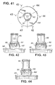
- FIG. 1 a filter assembly constructed in accordance with a preferred representative embodiment of the subject disclosure and designated generally by reference numeral 10.
- Filter assembly 10 is configured for use in conjunction with a fluid processing system that includes an inlet conduit 12 for delivering unfiltered process fluid into the filter assembly and an outlet conduit 14 for delivering filtered process fluid from the filter assembly 10.
- Filter assembly 10 is preferably mounted to a supporting structure associated with the fluid processing system by a bracket 16.
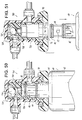
- filter assembly 10 includes a unique rotary valve assembly 18 that consists of a head portion 20 defining an interior chamber having an inlet port 22 for communicating with inlet conduit 12 and an outlet port 24 for communicating with outlet conduit 14.
- Rotary valve assembly 18 further includes a valve member 26 configured for reception within the interior chamber of head portion 20 in such a manner so as to facilitate rotation of the valve member relative to the head portion between an open position wherein fluid is permitted to flow through the filter assembly and a closed position wherein flow through the filter assembly is restricted. (See FIGS. 10-11 ).
- Valve member 26 includes an inlet orifice 32 for communicating with the inlet port 22 of head portion 20 and an outlet orifice 34 for communicating with the outlet port 24 of head portion 20. (See FIGS. 6-7 ).
- the body of valve member 26 includes recesses 36a and 38a for accommodating upper and lower O-ring seals 36 and 38.
- O-ring seal 36 serves to sealingly isolate the inlet flow from the outlet flow within the interior chamber of head portion 20 during operation, while O-ring seal 38 prevents leakage to atmosphere.
- filter assembly 10 further includes a replaceable filter cartridge 40 constructed in accordance with a preferred representative embodiment of the present disclosure.
- Filter assembly 10 is adapted and configured to ensure that replacement cartridge 40 is compatible with the fluid processing system with which it is associated.
- the filter cartridge 40 and valve portion 26 are provided with keyed mating structures that ensure compatibility therebetween, and thus prevent the accidental or intentional installation of an incompatible or inferior replacement cartridge, which could jeopardize the integrity of the fluid processing system.
- replaceable filter cartridge 40 includes a generally cylindrical body portion 42 enclosing filter media for filtering process fluid.
- body portion 42 enclosing filter media for filtering process fluid.
- filter media for filtering process fluid.
- An end cap 44 encloses the body portion 42, and a cylindrical neck portion 46 depends from the end cap 44.
- end cap 44 and body portion 42 can be joined together by sonic welding, spin welding or other similar methods known in the art.
- the neck portion 46 of filter cartridge 40 is adapted and configured for reception with the interior cavity of valve member 26 (see FIGS.
- one of a plurality of possible alternative representative embodiments could include a replaceable filter cartridge 40 wherein there is no difference in the diameter of the cylindrical body portion 42 and the cylindrical neck portion 46, thus, there is no differentiation between the cylindrical bottom portion 42 and the cylindrical neck portion 46 and, thus, the location of the cam lugs 62 and 64 need only be operatively positioned on the replaceable filter cartridge 40 such that the filter cartridge 40 is operatively connected to the intermediate support flange 70 that depends from mounting bracket 16.
- the upper section 46a defines a radial inlet passage 52 for receiving unfiltered process fluid entering the valve member 26 through inlet orifice 32 and directing the fluid into the body portion 42 of filter cartridge 40.
- the upper section 46a further defines an axial outlet passage 54 for delivering filtered process fluid from the interior of body portion 42 to the interior cavity of valve member 26 for egress through the outlet orifice 34 into the interior chamber of head portion 20.
- the inlet and outlet passages in the neck portion could be reversed such that the inlet flow is axial and the outlet flow is radial.
- the inlet and outlet passages 52 and 54 are sealingly isolated from one another by an upper O-ring seal 56 positioned at the upper end of neck portion 46.
- a second lower O-ring seal 58 is positioned below the radial inlet passage 52 to sealingly engage the neck portion 46 within the interior chamber of the valve member 26 and prevent the leakage of unfiltered process fluids from filter assembly 10 while in operation.
- a pair of diametrically opposed inclined cam lugs 62 and 64 project radially outwardly from the lower section 46b of neck portion 46.
- Cam lugs 62 and 64 are dimensioned and configured to facilitate rotational engagement of the filter cartridge within an intermediate support flange 70 that depends from mounting bracket 16.
- a central aperture 75 extends through support flange 70 for receiving the neck portion 46 of filter cartridge 40.
- a pair of diametrically opposed cam ramps 72 and 74 project radially into central aperture 75 for interacting with the inclined lower surfaces of cam lugs 62 and 64.
- the cam ramps 72 and 74 are spaced from one another to allow the cam lugs 62 and 64 to fit therebetween when the neck portion is extended through aperture 75 during assembly, and they are inclined along their arc length to facilitate rotational engagement of the filter cartridge with support flange 70, as illustrated in FIG. 4 .
- support flange 70 further includes a recessed seating area 76 defined by annular retaining wall 78 and configured to receive and retain the head portion 20 of filter assembly 10.
- Diametrically opposed arcuate retention ribs 82 and 84 project inwardly from retaining wall 78 to frictionally engage with corresponding ramped engagement struts 92 and 94 that project radially outwardly from the lower region of head portion 20 when the head portion 20 is rotatably engaged within the recessed seating area 76 during assembly.
- Stop surfaces 82a and 84a are associated with retention ribs 82 and 84, respectively, for limiting the movement of head portion 20 within seating area 76.
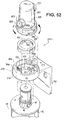
- the head portion 20 and support flange 70 may be adapted and configured to cooperate and engage with one another in a manner described hereinbelow with respect to filter assembly 800 and illustrated in FIGS. 52-53 .
- the annular retaining wall 78 of support flange 70 is also configured to accommodate and support a shroud 90, which is configured to house and protect the rotary valve assembly 18 of filter assembly 10.
- the shroud 90 includes lateral apertures, i.e., aperture 92, for accommodating inlet and outlet conduits 12 and 14.
- cam lugs 62 and 64 are adapted and configured for reception within a pair of corresponding diametrically opposed reception areas 102 and 104 formed within the interior cavity 25 of valve member 26. More particularly, the upper surface of each cam lug 62, 64 is provided with a unique key formation having, in this case, a plurality of spaced apart axially projecting teeth that are adapted and configured to engage and mate with a corresponding set of spaced apart recesses formed within the reception areas of the valve member 26. This mating arrangement is designed to ensure replacement cartridge compatibility by only permitting replacement of a filter cartridge having a keyed surface formation that corresponds with the surface features of the reception areas in the valve member.
- each cam lug (62, 64) includes three spaced apart teeth (62a-62c, 64a-64c) and each reception area (102, 104) within the valve member 26 includes three corresponding recesses (102a-102c, 104a-104c) for accommodating the teeth when the neck portion 46 of cartridge 40 is received by valve member 26.
- the number of teeth that define the key formation on each cam lug can vary within the scope of this disclosure (see for example FIGS. 18-40 ), as can the surface geometry of the key formation (see for example FIGS. 13-17 ).
- the reception area in the rotary valve member would have a corresponding mating configuration to accommodate the key formation formed on the cam lugs.
- the key configuration on one lug could be different from the key configuration of the opposed lug. This will dramatically increase the number of possible key combinations available to a filter manufacturer.
- the neck portion 46 of the filter cartridge 40 is inserted through the central aperture 75 of support flange 70, with the cam lugs 62 and 64 positioned between the diametrically opposed cam ramps 72 and 74.
- the valve member 26 is in the "off" position to receive the neck portion 46.
- the inlet and outlet orifices 32, 34 of valve member 26 are not aligned with the inlet and outlet ports 42, 44 of head portion 20.
- the teeth (62a-62c, 64a-64c) forming the keyed engagement surface of cam lugs 62 and 64 extend into the corresponding recesses (102a-102c, 104a-104c) of recessed areas 102 and 104 and mate therewith.
- valve member 26 Once the neck portion 46 of filter cartridge 40 has been intimately engaged within the interior chamber of valve member 26, the cartridge and valve member may be rotated in a counter-clockwise direction with respect to the support flange 70 and head portion 20, as illustrated in FIG. 11 .
- the cam lugs 62, 64 projecting from neck portion 46 translate against the cam ramps 72, 74, causing the filter cartridge 40 to move helically upwardly in an axial direction.
- valve member 26 is rotated into the "on" or open position, wherein the inlet and outlet orifices 32, 34 of the valve member 26 are aligned with the inlet and outlet ports 42, 44 of head portion 20 to allow fluid to flow through the filter assembly 10.
- cam lugs of a replacement filter cartridge introduced into the system are not configured to mate with the reception areas of the valve member, i.e., if the cam lugs have no keyed surface formation, which may be indicative of an unauthorized after-market filter cartridge, the cam lugs will interfere with and be unable to engage the reception areas in the valve member. Consequently, because the inclined cam surfaces of the cam lugs 62, 64 will be located below the inclined surfaces of the cam ramps 72, 74, the cam lugs will be unable to traverse the cam ramps. As a result, the cam lugs will be unable to effect rotation of the valve member into the "on" position to permit fluid to flow through the assembly. This will ensure replacement cartridge compatibility by preventing the use of inferior or unauthorized replacement filter cartridges.
- the key formation shown in the exemplary representative embodiment of FIGS. 3-11 corresponds to the key formation illustrated in FIG. 22 , which is selected from a group of key formations having five available tooth positions.
- the first, fourth and fifth teeth are present, while the second and third teeth are absent.
- the key formation illustrated in FIGS. 3-11 , and 22 may be represented by the numerical expression (1, 0, 0, 1, 1).
- FIGS. 2 and 12 A cartridge having a neck portion with diametrically opposed cam lugs that include such a formation referred to herein as a skeleton key formation, is illustrated in FIGS. 2 and 12 and is designated generally by reference numerals 40 and 140 respectively.
- the cam lugs 162 and 164 of filter cartridge 140 includes a skeleton key formation defined by a tooth formation wherein only the first and fifth tooth positions are filled with teeth (i.e., teeth 162a, 162b).
- This skeleton key is represented by the numerical expression (1, 0, 0, 0, 1). It should be understood that, in a five position key formation, the first and fifth position will always be filled, and, conversely, the recessed areas of the valve member will always have a recess located in the complementary positions.
- Table 2 sets forth the available tooth combinations for the five position key formation associated with the opposed cam lugs 162 and 1 64 of filter cartridge 140 and illustrated in FIGS. 3-11 and 21-27 .
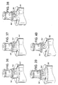
- Table 1 sets forth the available tooth configurations for the four position key formation associated with the opposed cam lugs 262 and 264 of filter cartridge 240 illustrated in FIGS. 18-20 .
- the skeleton key formation which is not shown and is represented by the numerical expression (1, 0, 0, 1) there are three available tooth configurations for a four position key formation.
- Table 3 sets forth the available tooth configurations for the six position key formation associated with the opposed cam lugs 362 and 364 of replaceable filter cartridge 340 as illustrated in FIGS. 28-41 .
- the skeleton key formation which is not shown and is represented by the numerical expression (1, 0, 0, 0, 0, 1) there are fifteen available tooth configurations for a six position key formation.
- N 2 n-2 -1
- each manufacturer could offer a unique set of replacement filter cartridge, with each cartridge in the set having a different keyed surface formation provided on the camming lugs thereof, for mating with corresponding reception areas in a valve member supported within a particular type of appliance.
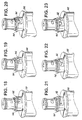
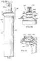
- FIGS. 13-17 there are illustrated a series of replacement filter cartridges constructed in accordance with a preferred representative embodiment of the subject disclosure each having a different keyed surface formation associated therewith.
- FIGS. 13, 14, 16 and 17 illustrate filter cartridges 403, 404, 406, and 407, respectively, with cam lugs 463, 464, 466 and 467 having keyed surface formations with portions that project both radially outwardly from the lugs as well as in an axial direction.
- cam lug 463 in FIG. 13 includes two teeth 463a, 463b which project axially and radially from the lug.
- FIG. 14 includes two axially projecting teeth 464a and 464c and one tooth 464b that project both radially and axially.
- FIG. 16 illustrates a cam lug 466 having an enlarged radially and axially projecting tooth 466a and a smaller axially projecting tooth 466b.
- Cam lug 467 in FIG. 17 includes two axially projecting teeth 467a and 467b and the majority of the cam lug itself project radially outwardly from the neck portion of the filter cartridge 407.
- a compatible rotary valve member would have recessed areas with mating features that correspond to the radially and axially extending keyed surface formations of cam lugs 463, 464, 466 and 467.
- FIG. 15 illustrates another replacement filter cartridge 405 constructed in accordance with a preferred representative embodiment of the subject disclosure wherein the keyed surface formation provided on the cam lug 465 thereof is defined by a curved surface 465a.
- a compatible valve member for filter cartridge 405 would have reception areas with corresponding curved recesses to ensure compatibility with cartridge 405.
- Filter cartridge 540 includes three cam lugs 561, 562 and 563 that are circumferentially spaced apart about the periphery of neck portion 546. Each cam lug has a keyed surface formation thereon for mating with a corresponding recessed area of a compatible rotary valve member 26. As illustrated in FIGS. 42-44 , the keyed surface formations of cam lugs 561-563 are derived from a five tooth configuration (see Table 2), and each cam lug has a different key pattern formed thereon.
- cam lug 561 has a first keyed surface formation that may be represented by the numerical expression (1, 0, 1, 0, 1)
- cam lug 562 has a second keyed surface formation that may be represented by the numerical expression (1, 0, 0, 1, 1)
- cam lug 563 has a third keyed surface formation that may be represented by the numerical expression (1, 1, 0, 0, 1). It is also envisioned that cam lugs 561-563 could each have the same keyed surface formation provided thereon.
- Filter cartridge 640 includes two sets of diametrically opposed cam lugs that include cam lugs 661-664.
- the first set of opposed cam lugs 661, 663 are positioned at a first axial height on neck portion 646, and the second set of opposed cam lugs 662, 664 are positioned at a second axial height on neck portion 646.
- each cam lug has a keyed surface formation thereon for mating with a corresponding recessed area of a compatible rotary valve member 26. As illustrated in FIGS.
- cam lugs 661-664 are derived from a five tooth configuration (see Table 2).
- Cam lugs 661 and 664 have the same keyed surface formation thereon that may be represented by the numerical expression (1, 0, 0, 1, 1), while cam lugs 662 and 663 both have another keyed surface formation thereon that may be represented by the numerical expression (1, 1, 0, 0, 1).
- cam lugs 661-664 could each have the same keyed surface formation provided thereon, or, in the alternative, each cam lug could have a different keyed surface formation provided thereon.
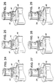
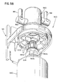
- Filter assembly 700 includes a head portion 720 enclosing a rotary valve member 726 that has a mechanism for minimizing leakage during cartridge replacement.
- the mechanism includes a floating check-ball 728 and an associated valve seat 730.
- FIG. 51 during normal service, when process fluid is flowing through the system, the outlet flow pressure of the filtered fluid causes the check-ball 728 to remain in an unseated position.
- filter assembly 800 differs from the previously described representative embodiments of the subject disclosure in that the assembly does not include a rotary valve member, such as the valve member 18 of filter assembly 10. Instead, as best seen in FIG. 53 , filter assembly 800 includes a head portion 820 with an interior bore 825 having a lower region 825a configured to support an annular insert in the form of a key ring 818. Key ring 818 defines diametrically opposed reception areas 802, 804 for mating with corresponding keyed surface formations on the cam lugs 62, 64 formed on the neck portion 26 of a replacement filter cartridge 40, for example. In accordance with the subject disclosure, to ensure the integrity of the system with which filter assembly 800 is associated, a compatible replacement cartridge must have cam lugs with keyed surface formations that mate with the recessed areas of the key ring 818.
- filter assembly 800 further includes a mounting bracket 816 having a support flange 870 depending therefrom for facilitating rotational engagement of a replacement filter cartridge 40 with head member 820 and the associated key ring 818.
- a central aperture 875 extends through support flange 870 to receive the neck 46 of filter cartridge 40, and a pair of diametrically opposed cam raps 872 and 874 project radially into central aperture 875 for operatively interacting with the inclined lower surfaces of cam lugs 62, 64 when filter cartridge 40 is engaged with head portion 820.
- Support flange 870 further includes a recessed seating area 876 defined by an annular retaining wall 878 configured to receive and retain the head portion 820.
- head portion 820 includes a pair of diametrically opposed ramped cam struts 882 and 884 for operatively engaging a pair of diametrically opposed retention flanges 892 and 894 projecting radially inwardly from the retaining wall 878.
- ratchet nibs 882a and 884a project outwardly from the lower region of head portion 820 for engagement within corresponding notches 892a and 894a formed in retention flanges 892 and 894, respectively.
- head portion 820 and support flange 870 interact and engage may also be employed in conjunction with the filter assembly 10 described hereinabove, whereby head portion 20 and support flange 70 would be adapted and configured to interact and engage in a substantially similar manner.
- a key ring 818 having particular configuration of recesses which may be selected from a set of key rings each having different recess configurations, is first inserted into the lower region 825a of interior bore 825 of head potion 820.
- the head portion is then rotatably engaged within the seating area 876 of support flange 870.
- a filter cartridge 40 is brought into approximation with the head portion 820 by inserting the neck portion 46 of the cartridge through the central aperture 875 of support flange 870, allowing the camming lugs 62, 64 to pass between the opposed cam ramps 872, 874 projecting radially into aperture 875.
- the keyed surface formations of the cam lugs 62, 64 mate with the corresponding recessed areas 802, 804 in key ring 818, provided of course that the cartridge and key ring are compatible with one another.
- This relative movement causes the key ring 818 to rotate within interior bore region 825a and causes the neck portion 46 of filter cartridge 40 to move axially into the upper region 825b of the interior bore 825 of head portion 820, until such time as the neck portion of the filter cartridge is sealingly received therein.
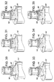
- filter assembly 900 is configured for use in conjunction with a fluid processing system that includes an inlet conduit 912 for delivering unfiltered process fluid into the filter assembly and an outlet conduit 914 for delivering filtered process fluid from the filter assembly 900.
- Filter assembly 900 is preferably mounted to a supporting structure associated with the fluid processing system by a bracket 916.
- filter assembly 900 includes a unique rotary valve assembly 918 that includes a head portion 920 defining an interior chamber having an inlet port 922 for communicating with inlet conduit 912 and an outlet port 924 for communicating with outlet conduit 914.
- Rotary valve assembly 918 further includes a valve member 926 configured for reception within the interior chamber of head portion 920 in such a manner so as to facilitate rotation of the valve member 926 relative to the head portion 920 between an open position wherein fluid is permitted to flow through the filter assembly and a bypass position wherein unrestricted fluid flows through the filter head from inlet to outlet. (See FIGS. 59-60 ).
- Valve member 926 includes an inlet orifice 932 for communicating with the inlet port 922 of head portion 920 and an outlet orifice 934 for communicating with the outlet port 924 of head portion 920. (See FIG. 61 )
- the body of valve member 926 includes a recess 931a, shown in FIG. 61 , surrounding the inlet orifice 932 for accommodating an O-ring seal 931, also shown in FIG. 61 , which serves to facilitate fluid-tight junction of the inlet orifice 932 and the inlet port 922.
- the valve member 926 also has a recess 933a surrounding the outlet orifice 934 for accommodating an O-ring seal 933, shown in FIG.
- the body of the valve member 926 further includes a recess 938a for accommodating an O-ring seal 938 (See FIGS. 61-64 ).
- the O-ring seal 938 serves to facilitate sealing engagement of the valve member 926 within the interior chamber of head portion 920 and to prevent leakage of the process fluid to atmosphere.
- filter assembly 900 further includes a replaceable filter cartridge 940 constructed in accordance with a preferred representative embodiment of the subject disclosure.
- Filter assembly 900 is adapted and configured to ensure that replacement cartridge 940 is compatible with the fluid processing system with which it is associated.
- the filter cartridge 940 and valve member 926 are provided with keyed mating structures that ensure compatibility therebetween, and thus prevent the accidental or intentional installation of an incompatible or inferior replacement cartridge, which could jeopardize the integrity of the fluid processing system.
- replaceable filter cartridge 940 includes a generally cylindrical body portion 942 enclosing filter media for filtering process fluid.
- the body portion 942 includes a top cap 944, which preferably forms an integral part of the body portion 942.
- the top cap 944 and body portion 942 may be formed separately and then joined together by sonic welding, spin welding or other similar methods known in the art.
- the top cap 944 has a neck portion 946 depending therefrom.
- the neck portion 946 of filter cartridge 940 is adapted and configured for reception within the interior cavity of valve member 926 (See FIGS. 54 , 56 , 58-61 ) and includes an upper section 946a and a lower portion 946b.
- the neck portion 946 defines a plurality of axial passages 952.
- the upper section 946a preferably also defines a plurality of sloped axially-aligned protrusions 951, which project radially outwardly from the upper section 946a, for dividing the flow of fluid entering the axial passages 952.
- unfiltered process fluid enters the interior chamber of the valve member 926 through the inlet orifice 932, flows between the protrusions 951 and through the axial passages 952, and then enters the body portion 942 (see FIG. 55 ) of the filter cartridge 940.
- the upper section 946a further defines an axial outlet passage 954 for delivering filtered process fluid from the interior of body portion 942 to the interior cavity of valve member 926 for egress through the outlet orifice 934 and the port 924 out of the head portion 920.
- the inlet and outlet passages 952 and 954 are sealingly isolated from one another by an upper O-ring seal 956 positioned at the upper end of neck portion 946 (see FIG. 61 ).
- a second lower O-ring seal 958 is positioned below the inlet of the radial passages 952 to sealingly engage the neck portion 946 within the interior chamber of the valve member 926 and prevent the leakage of unfiltered process fluids from filter assembly 900 while in operation.
- a pair of diametrically opposed cam lugs 962 and 964 project radially outwardly from the lower section 946b of neck portion 946.
- Cam lugs 962 and 964 are dimensioned and configured to facilitate rotational engagement of the filter cartridge within an intermediate support flange 970 that depends from mounting bracket 916.
- a central aperture 975 extends through support flange 970 for receiving the neck portion 946 of filter cartridge 940.
- a pair of diametrically opposed cam ramps 972 and 974 project radially into central aperture 975 for interacting with the lower surfaces of cam lugs 962 and 964.
- each cam lug, 962 and 964 includes a leading inclined surface 963.
- Leading inclined surface 963 is adapted and configured to facilitate rotational engagement of the filter cartridge with the cam ramps 972 and 974 of the support flange 970, as illustrated in FIGS. 58-60 and 62-64 .
- support flange 970 further includes a recessed seating area 976 defined by annular retaining wall 978 and configured to receive and retain the head portion 920 of filter assembly 900.
- Diametrically opposed arcuate retention ribs 982 and 984 project inwardly from retaining wall 978 to frictionally engage with corresponding engagement struts 992 and 994 (see FIG. 61 ) that project radially outwardly from the lower region of head portion 920, when the head portion 920 is rotatably engaged within the recessed seating area 976 during assembly.
- the head portion 920 and support flange 970 may be adapted and configured to cooperate and engage with one another in a manner described herein with respect to filter assembly 800 and as illustrated in FIGS. 52-53 .
- annular retaining wall 978 of support flange 970 may be also configured to accommodate and support a shroud (not shown), such as the shroud 90, for housing and protecting the rotary valve assembly 918 of filter assembly 900.
- a shroud such as the shroud 90
- cam lugs 962 and 964 See FIGS. 54 and 56 ) may be adapted and configured for reception within a pair of corresponding diametrically opposed reception areas 1002 and 1004, best shown in FIG. 57 , formed within the interior cavity 925 of valve member 926.
- each cam lug 962, 964 is provided with a unique key formation having, in this exemplary representative embodiment, a plurality of spaced apart axially projecting teeth that are adapted and configured to engage and mate with a corresponding set of spaced apart recesses formed within the reception areas 1002 and 1004 of the valve member 926.
- This mating arrangement is designed to ensure replacement cartridge's compatibility by only permitting replacement of a filter cartridge having a keyed surface formation that corresponds to the surface features of the reception areas in the valve member.
- the key formation on each cam lug (962, 964) includes three spaced apart teeth (962a-962c, 964a-964c).
- Other configurations of the key formation may also be used, e.g., those described herein.
- the exemplary representative embodiment shown in FIGS. 54-64 the reception areas, 1002 and 1004, also include a rib member 1006.
- the two corresponding reception areas would typically include corresponding recesses for each spaced apart tooth formed on the cam lugs.
- only a single recess is provided with rib member 1006.
- This configuration for the reception areas is more representative of a skeleton key formation.
- the reception area configurations previously disclosed with respect to alternative embodiments of the present disclosure can be applied to filter assembly 900.
- the number of teeth that define the key formation on each cam lug (962, 964) can vary within the scope of this disclosure (see for example FIGS. 18-40 ), as can the surface geometry of the key formation (see for example FIGS. 13-17 ).
- the reception areas (1 002, 1004) in the rotary valve member 926 would have a corresponding mating configuration to accommodate the key formation formed on the cam lugs.
- the key configuration on one lug could be different from the key configuration of the opposed lug. This will dramatically increase the number of possible key combinations available to a filter manufacturer.
- the neck portion 946 of the filter cartridge 940 is inserted through the central aperture 975 of support flange 970, with the cam lugs 962 and 964 positioned between the diametrically opposed cam ramps 972 and 974 (See FIG. 54 ).
- the valve member 926 should be in the bypass position to receive the neck portion 946 (See FIG. 60 ). In that position, the inlet and outlet orifices 932, 934 of valve member 926 are not aligned with the inlet and outlet ports 922, 924 of head portion 920.
- the process fluid entering the inlet port 922 flows into the interior chamber of the head portion 920 and around the outer surface of the valve member 926. Sealing engagement of the valve member 926 within the head portion 920, e.g., facilitated by the O-ring seal 938, prevents leakage of the process fluid flowing around the valve member 926 into atmosphere.
- cam lugs 962 and 964 are positioned into the corresponding reception areas 1002 and 1004 and are caused to mate therewith.
- trailing inclined surfaces 965 (See FIG. 56 ), which are associated with cam lugs 962 and 964, are adapted and configured for engagement with inclined surfaces 1008 formed in reception areas 1002 and 1004.
- the formation of trailing and leading inclined surfaces 963 and 965 on cam lug 962 and 964 facilitates the rotational engagement of the filter cartridge 940 with the support flange 970 and the opening of valve member 926.
- the cartridge and valve member may be rotated, e.g., presently preferably, in a counter-clockwise direction from the filter position illustrated in FIG. 59 to the bypass position illustrated in FIG. 60 , with respect the support flange 970 and head portion 920.
- the cam lugs 962, 964 projecting from neck portion 946 translate against the cam ramps 972, 974, causing the filter cartridge 940 to move helically upwardly in an axial direction.
- valve member 926 is rotated into the "on" or open position, wherein the inlet and outlet orifices 932, 934 of the valve member 926 are aligned with the inlet and outlet ports 922, 924, respectively, of head portion 920 to allow fluid to flow through the filter assembly 900.
- FIG. 61 illustrates an assembled filter assembly according to an exemplary preferred representative embodiment of the subject disclosure, wherein filter cartridge 940 is engaged with support flange 970 and valve member 926 is in the open position.
- cam lugs of a replacement filter cartridge introduced into the system are not configured to mate with the reception areas of the valve member, i.e., if the cam lugs have no keyed surface formation, which may be indicative of an unauthorized after-market filter cartridge, the cam lugs will interfere with and be unable to engage the reception areas in the valve member. Consequently, because the cam lugs 962, 964 will be located below the inclined surfaces of the cam ramps 972, 974, the cam lugs will be unable to traverse the cam ramps. As a result, the cam lugs will be unable to effect rotation of the valve member into the "on" position to permit fluid to flow through the assembly. This will ensure replacement cartridge compatibility by preventing the use of inferior or unauthorized replacement filter cartridges.
- FIGS. 62-64 which illustrate the interaction of the cam lugs 962, 964 (opposite side, not shown) with the corresponding reception areas 1002 and 1004 formed in the interior cavity of valve member 926.
- the neck portion 946 of filter cartridge 940 is fully inserted into the interior cavity 925 of valve member 926 and cam lugs 962, 964 are positioned within reception areas 1002 and 1004.
- FIGS. 62-64 illustrate the interaction of the cam lugs 962, 964 (opposite side, not shown) with the corresponding reception areas 1002 and 1004 formed in the interior cavity of valve member 926.
- trailing inclined surfaces 965 contact inclined surfaces 1008 formed in reception areas 1002, 1004 and slide along the inclined surfaces 1008, so that filter cartridge 940 is forced in a downward direction until it is disengaged from within the interior cavity 925 of valve member 926.
- valve member 926 rotates from an open position to a "bypass" position within head portion 920.
- trailing inclined surfaces 965 contact the inclined surfaces 1008 formed in reception areas 1002. The inclined surfaces 965 slide along the inclined surfaces 1008 when the filter cartridge 940 is rotated in a counter-clockwise direction, so that filter cartridge 940 is forced to move in an upward direction and engagement with support flange 970 is, thus, facilitated.
- Filter assembly 1100 is used in conjunction with a fluid processing system that includes an inlet conduit 1112 for delivering untreated or unprocessed fluid to a replaceable filter/treatment cartridge 1115, and an outlet conduit 1114 for carrying treated or processed fluid from the replaceable cartridge 1115.
- Filter assembly 1100 is supported relative to the fluid processing system with which it is associated by a mounting bracket 1116, which may be hinged for ease of utilization.
- Inlet conduit 1112 and outlet conduit 1114 are oriented parallel to one another, and therefore, the filter assembly 1100 is particularly adapted and configured to accommodate this configuration, as discussed in more detail below.
- filter assembly 1100 includes a head member 1118 having an inlet passage 1120 and an outlet passage 1122.
- a connector 1124 is provided at the terminal end of inlet conduit 1112 for operative engagement with the inlet passage 1120 of head member 1118
- a connector 1126 is provided at the terminal end of outlet conduit 1114 for operative engagement with the outlet passage 1122 of head member 1118.
- Head member 1118 includes opposed arcuate camming ramps 1128a, 1128b, which cooperate with corresponding ramped camming surfaces defined within an engagement aperture 1130 formed in the mounting bracket 1116 supporting filter assembly 1110. In use, rotation of head member 1118 relative to aperture 1130 facilitates cooperative interaction between the camming ramps and camming surfaces to releasably engage or otherwise mount the head member 1118 to bracket 1116.
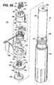
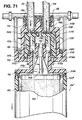
- Filter assembly 1100 further includes a valve member 1132, which is accommodated within a valve chamber 1134 formed within head member 1118 (see FIGS. 69 and 71 ).
- valve member 1132 includes a central reception bore 1133 for accommodating the neck portion 1135 of the replaceable filter cartridge 1115 (see FIGS. 69 and 71 ).
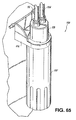
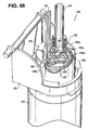
- Valve member 1132 is adapted and configured for rotation within valve chamber 1134 between a filter mode/position ( FIGS. 68 and 69 ) wherein untreated fluid is directed into the filter cartridge 1115 and a bypass mode/position ( FIGS. 70 and 71 ) wherein fluid flow to the filter cartridge 1115 is prevented or otherwise blocked.
- the filter cartridge 1115 can be conveniently removed from the filter assembly, discarded and replaced.
- untreated processes fluid will continue to flow therebetween.
- Valve member 1132 includes an inlet path 1136 and an outlet path 1138.
- the inlet path 1136 of valve member 1132 communicates with the inlet passage 1120 of head member 1118
- the outlet path 1138 of valve member 1132 communicates with the outlet passage 1122 of head member 1118.
- fluid may flow to and from the filter cartridge 1115, as discussed in more detail below.
- the bypass mode which is attained when the valve member 1132 is manually rotated a quarter turn or 90° from the position shown in FIGS. 68 and 69 to the position shown in FIGS.
- valve member 1132 is moved out of communication with the inlet passage 1120 of head member 1118 and the outlet path 1138 of valve member 1132 is moved out of communication with the outlet passage 1122 of head member 1118. At such a time, fluid flow to and from the filter cartridge 1115 is prevented.
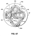
- a seal member 1140 is operatively associated with valve member 1132, and more particularly, the seal member 1140 is seated in a conforming or otherwise dimensionally corresponding seating area 1142 formed on or otherwise formed in the upper surface 1132a of valve member 1132. Seal member 1140 is positioned to provide a water-tight/air-tight seal against an opposing surface of valve chamber 1134, and is monolithically formed from an elastomeric material, such as for example, Neoprene or a like material.
- seal member 1140 includes a plurality of separate sealing areas 1140a-1140d.
- seal member 1140 includes a first seal portion 1140a of generally circular configuration, which is dimensioned to sealingly isolate the inlet path 1136 of the valve member 1132, when the filter member is in the filter mode/position shown in FIGS. 68 and 69 .
- Seal member 1140 includes a second seal portion 1140b of generally oval configuration, which is dimensioned to sealingly isolate the outlet path 1138 of the valve member 1132, when the valve member is in the filter position.
- a stabilizing strut 1145 connects the generally circular seal portion 1140a to the generally oval seal portion 1140b to add rigidity to the seal member.
- Seal member 1140 includes a third seal portion 1140c of generally triangular configuration, and a fourth seal portion 1140d of generally triangular configuration.
- seal portions 1140c, 1140d sealingly isolate the inlet and outlet passage 1120, 1122 of the head member 1118 from the atmosphere.
- seal portions 1140c, 1140d form a bypass flow path or trough which allows the inlet and outlet passages 1120, 1122 to remain in fluid communication with one another. Consequently, untreated process fluid will continue to flow between the inlet and outlet passages 1120, 1122 of head member 1118.
- the replaceable filter cartridge 1115 includes a generally cylindrical sump 1150, which is dimensioned and configured to support a filter element 1152.
- filter element 1152 is an extruded carbon block element.
- other types of filter elements can be employed without departing from the spirit or scope of the subject disclosure.
- a pleated filter element or a spiral wound filter element can be employed.
- the cartridge 1115 need not take the form of a filter, but in the alternative it can take the form of a cartridge for providing an additive to a fluid stream or for otherwise conditioning a fluid steam.
- Filter element 1152 has a central bore 1153, into which processed fluid flows.
- a closed or blind end cap 1154 is positioned at the bottom end of filter element 1152 and an open end cap 1156 is positioned at the top end of filter element 1152.
- a freeze protection pad 1157 formed from a closed sell foam material is associated with end cap 1154.
- End cap 1156 includes an outlet tube 1158, which communicates with the central bore 1153.
- a sump cover 1160 encloses the interior of sump 1150, and is spin welded or otherwise fastened or affixed to the upper end of sump 1150.
- Sump cover 1160 includes a base portion 1162 from which extends the neck portion 1135 of filter cartridge 1115.
- Neck portion 1135 has a stepped construction defined by a lower, radially outer neck portion 1135a and an upper, radially inner neck portion 1135b.
- An outer O-ring seal 1137a surrounds the outer neck portion 1135a and an inner O-ring seal 1137b surrounds the inner neck portion 1135b.
- a fluid inlet 1164 is formed between the outer neck portion 1135a and the inner neck portion 1135b.
- Fluid inlet 1164 delivers untreated fluid into the interior of sump 1150.
- a fluid outlet 1166 is defined by the inner neck portion 1135b. Fluid outlet 1166 delivers treated fluid from the central bore 1153 of filter element 1152 by way of the outlet tube 1158 of end cap 1156.
- the neck portion 1135 of cartridge 1115 is accommodated with the interior bore 1133 of valve member 1132, as best seen in FIG. 69 .
- the central reception bore 1133 of valve member 1132 includes a radially inner bore portion 1168 for sealingly isolating the outlet port 1166 of filter cartridge 1115 and a radially outer bore portion 1170 for sealing isolating the inlet port 1164 of filter cartridge 1115.
- a pair of diametrically opposed keyed camming lugs 1172a, 1172b depend radially outwardly from the outer neck portion 1135a for cooperating with corresponding keyed engagement recesses 1174a, 1174b in the same manner as described previously herein with other representative embodiments of the subject disclosure, wherein the lugs and the recesses have mating surfaces to prevent the use of non-compatible filter cartridges within filtration assembly 1100.
- untreated fluid flows from the inlet conduit 1112 into the inlet passage 1120 of head member 1118.
- the untreated fluid then flows through the communicating inlet path 1136 of valve member 1132 and into the inlet 1164 in the neck portion 1135a of filter cartridge 1115.
- untreated fluid fills the sump 1150 of filter cartridge 1115 and flows radially inwardly through the carbon block filter element 1152 to the central bore 1154. Filtered fluid then flows from central bore 1154 of the filter element 1152, through the outlet tube 1158, to the outlet 1166 in the neck portion 1135b of filter cartridge 1115.
- the filtered fluid then flows through the outlet path 1138 of valve member 1132, into the communicating outlet passage 1122 of head member 1118, and exits the filter assembly 1100 by way of outlet conduit 1114.
- the first seal portion 1140a of seal member 1140 sealingly isolates the inlet path 1136 of the valve member 1132
- the second seal portion 1140b of seal member 1140 sealingly isolate the outlet path 1138 of the valve member 1132.
- valve member 1132 (accompanied by filter cartridge 1115) is rotated into or otherwise disposed in the bypass position within the valve chamber 1134 of head member 1118, untreated fluid is prevented or otherwise blocked from flowing from the inlet passage 1120 of head member 1118 to the inlet path 1136 of valve member 1132.
- the outlet path 1138 of valve member 1132 is moved out of communication with the outlet passage 1122 of head member 1118.
- the third and fourth seal portions 1140c, 1140d of seal member 1140 sealingly isolate the inlet and outlet passages 1120, 1122 of head member 1118 from the atmosphere.
- a flow path is provided between the inlet and outlet passage 1120, 1122 of head member 1118, which permits untreated process fluid to flow therebetween. At such as time, the replaceable filter cartridge 1115 can be removed from the valve member 1132 without loss of process fluid.
Landscapes
- Chemical & Material Sciences (AREA)
- Chemical Kinetics & Catalysis (AREA)
- Lubrication Details And Ventilation Of Internal Combustion Engines (AREA)
- Separation Using Semi-Permeable Membranes (AREA)
- Water Treatment By Sorption (AREA)
- Filtering Of Dispersed Particles In Gases (AREA)
- Filtration Of Liquid (AREA)
- Sliding Valves (AREA)
- Preventing Unauthorised Actuation Of Valves (AREA)
- Details Of Valves (AREA)
Applications Claiming Priority (2)
| Application Number | Priority Date | Filing Date | Title |
|---|---|---|---|
| US10/976,571 US7407148B2 (en) | 2000-04-20 | 2004-10-29 | Rotary valve assembly for fluid filtration system |
| PCT/US2005/038964 WO2006050114A1 (en) | 2004-10-29 | 2005-10-27 | Rotary valve assembly for fluid filtration system |
Publications (2)
| Publication Number | Publication Date |
|---|---|
| EP1824577A1 EP1824577A1 (en) | 2007-08-29 |
| EP1824577B1 true EP1824577B1 (en) | 2009-05-06 |
Family
ID=35614184
Family Applications (1)
| Application Number | Title | Priority Date | Filing Date |
|---|---|---|---|
| EP05815356A Expired - Lifetime EP1824577B1 (en) | 2004-10-29 | 2005-10-27 | Rotary valve assembly for fluid filtration system |
Country Status (11)
| Country | Link |
|---|---|
| US (1) | US7407148B2 (enExample) |
| EP (1) | EP1824577B1 (enExample) |
| JP (1) | JP2008519212A (enExample) |
| KR (1) | KR101278401B1 (enExample) |
| CN (1) | CN101052451B (enExample) |
| AT (1) | ATE430612T1 (enExample) |
| AU (1) | AU2005302492A1 (enExample) |
| BR (1) | BRPI0518065A (enExample) |
| DE (1) | DE602005014379D1 (enExample) |
| MX (1) | MX2007004907A (enExample) |
| WO (1) | WO2006050114A1 (enExample) |
Cited By (3)
| Publication number | Priority date | Publication date | Assignee | Title |
|---|---|---|---|---|
| EP3672914A1 (en) * | 2017-08-23 | 2020-07-01 | Formaster S.A. | A zone cartridge for water treatment for a zone device for water treatment, a head of a zone device for water treatment and a zone device for water treatment comprising such a cartridge and such a head |
| EP3672917A1 (en) * | 2017-08-23 | 2020-07-01 | Formaster S.A. | A cartridge for a water treatment for a device for a water treatment, a head of a device for a water treatment and a device for water treatment comprising such a cartridge and such a head |
| WO2025242809A1 (en) * | 2024-05-22 | 2025-11-27 | European Water Care Ltd | Water filter unit and a head assembly therefor |
Families Citing this family (99)
| Publication number | Priority date | Publication date | Assignee | Title |
|---|---|---|---|---|
| USD332092S (en) * | 1991-03-11 | 1992-12-29 | Kun-Nan Lo | Monitor |
| US6458269B1 (en) * | 2000-04-20 | 2002-10-01 | Cuno Incorporated | Keyed filter assembly |
| CN2741960Y (zh) * | 2004-10-28 | 2005-11-23 | 厦门建霖卫浴工业有限公司 | 净水器 |
| JP5001936B2 (ja) | 2005-05-16 | 2012-08-15 | スリーエム イノベーティブ プロパティーズ カンパニー | フィルタシステム用のスプール弁マニホールドの相互接続 |
| DE202005014071U1 (de) * | 2005-09-06 | 2007-01-18 | Oase Gmbh | Pumpe für Teich-, Aquarien- o.dgl. Anlagen |
| US7651070B2 (en) * | 2006-01-19 | 2010-01-26 | Clean & Clear Corporation | Canter element controlled combination manifold, valve and filter module system |
| US20070284296A1 (en) | 2006-06-08 | 2007-12-13 | Paragon Water Systems | Filter cartridge and head assembly with internal shutoff valve |
| KR20090024809A (ko) * | 2006-06-27 | 2009-03-09 | 코닌클리케 필립스 일렉트로닉스 엔.브이. | 정수 시스템과 이 시스템용의 필터부재 |
| ES2589125T3 (es) | 2006-08-10 | 2016-11-10 | Aquis Wasser-Luft-Systeme Gmbh, Lindau | Cartucho de filtro de agua |
| DE102006044744C5 (de) * | 2006-09-20 | 2021-04-01 | Aquis Wasser-Luftsysteme GmbH Lindau, Zweigniederlassung Rebstein | Wasserfiltervorrichtung mit Verschlüsselungsstruktur |
| DE102007006970A1 (de) * | 2007-02-13 | 2008-09-04 | Brita Gmbh | Vorrichtung zur Behandlung von Wasser, insbesondere Filtervorrichtung,und Kartusche |
| USD562124S1 (en) * | 2007-03-08 | 2008-02-19 | Focal Point Products, Inc. | Clip unit for installing medallions |
| USD601238S1 (en) | 2007-03-20 | 2009-09-29 | Donaldson Company, Inc. | Filter cartridge |
| CN101678262B (zh) | 2007-03-20 | 2016-07-06 | 唐纳森公司 | 气溶胶分离器组件;部件和方法 |
| US8404029B2 (en) | 2007-06-14 | 2013-03-26 | Donaldson Company, Inc. | Crankcase ventilation filter arrangments; components; and, methods |
| WO2009005499A1 (en) * | 2007-07-02 | 2009-01-08 | Paragon Water Systems | Filter cartridge and head assembly with internal shutoff valve |
| US7867387B2 (en) * | 2007-07-19 | 2011-01-11 | Cummins Filtration Ip, Inc. | Standpipe with flow restriction valve, and filter cartridge |
| WO2009018454A2 (en) | 2007-08-02 | 2009-02-05 | Donaldson Company, Inc. | Crankcase ventilation filter assembly; components; and, methods |
| GB0715247D0 (en) * | 2007-08-04 | 2007-09-12 | Parker Hannifin Ltd | Filter assembly |
| GB0715269D0 (en) | 2007-08-04 | 2007-09-12 | Parker Hannifin Ltd | Filter assembly |
| US7959010B2 (en) * | 2008-03-14 | 2011-06-14 | Cummins Filtration Ip, Inc. | Standpipe with integrated regulator valve |
| US7540956B1 (en) * | 2008-03-21 | 2009-06-02 | Pentair Filtration, Inc. | Modular drinking water filtration system with removable and replaceable RO spindle |
| US20090236272A1 (en) * | 2008-03-21 | 2009-09-24 | Pentair Filtration, Inc. | Modular Drinking Water Filtration System with Keyed Attachment of Filter Head to Mounting Bracket and Modular Back Plates |
| US20090236277A1 (en) * | 2008-03-21 | 2009-09-24 | Pentair Filtration, Inc. | Modular Drinking Water Filtration System with Internal Sealing Between Valve Spindle and Head |
| US7662283B2 (en) | 2008-03-21 | 2010-02-16 | Pentair Filtration, Inc. | Modular drinking water filtration system with locking arrangement to assure filter cartridge compatibility |
| US7695619B2 (en) * | 2008-03-21 | 2010-04-13 | Pentair Filtration, Inc. | Modular drinking water filtration system with adapter rings for replaceable cartridges to assure proper fit |
| DE102008040319A1 (de) * | 2008-07-10 | 2010-01-14 | Deere & Company, Moline | Filteranordnung zum Filtern eines flüssigen oder gasförmigen Mediums |
| KR101614566B1 (ko) | 2008-09-05 | 2016-04-21 | 쓰리엠 이노베이티브 프로퍼티즈 컴파니 | 여과 시스템 |
| GB2465622B (en) * | 2008-11-27 | 2013-06-19 | Fairey Ceramics | Filter assembly with venting mechanism and automatic shut off valves for clean filter change |
| DE102009007389B3 (de) * | 2009-02-05 | 2010-04-15 | Hydac Filtertechnik Gmbh | Filtervorrichtung |
| US8920648B2 (en) * | 2009-02-25 | 2014-12-30 | Cummins Filtration Ip Inc. | No filter no run fluid filtration systems |
| US8240332B1 (en) | 2009-04-20 | 2012-08-14 | Aeromotive, Inc. | Internally mounted/externally accessible fuel supply unit for a fuel sump |
| USD610225S1 (en) | 2009-07-13 | 2010-02-16 | Paragon Water Systems | Key for a water filter assembly |
| KR101318423B1 (ko) * | 2011-06-24 | 2013-10-15 | 위니맥스 주식회사 | 정수필터 어셈블리 및 이를 구비한 냉장고 및 정수기 |
| USD654559S1 (en) | 2011-09-15 | 2012-02-21 | Whirlpool Corporation | Filter unit |
| US8950052B2 (en) | 2011-09-15 | 2015-02-10 | Whirlpool Corporation | Method of installing a filter unit |
| USD655377S1 (en) | 2011-09-15 | 2012-03-06 | Whirlpool Corporation | Filter unit |
| USD654563S1 (en) | 2011-09-15 | 2012-02-21 | Whirlpool Corporation | Filter unit |
| USD654565S1 (en) | 2011-09-15 | 2012-02-21 | Whirlpool Corporation | Filter unit |
| USD654561S1 (en) | 2011-09-15 | 2012-02-21 | Whirlpool Corporation | Filter unit |
| US8591736B2 (en) | 2011-09-15 | 2013-11-26 | Whirlpool Corporation | Water filter unit |
| USD654560S1 (en) | 2011-09-15 | 2012-02-21 | Whirlpool Corporation | Filter unit |
| USD655378S1 (en) | 2011-09-15 | 2012-03-06 | Whirlpool Corporation | Filter unit |
| US8413818B1 (en) | 2011-09-15 | 2013-04-09 | Whirlpool Corporation | Filter unit |
| USD654564S1 (en) | 2011-09-15 | 2012-02-21 | Whirlpool Corporation | Filter unit |
| US8845896B2 (en) | 2011-09-15 | 2014-09-30 | Whirlpool Corporation | Water filter system |
| USD654566S1 (en) | 2011-09-15 | 2012-02-21 | Whirlpool Corporation | Filter unit |
| USD654562S1 (en) | 2011-09-15 | 2012-02-21 | Whirlpool Corporation | Filter unit |
| US8580109B2 (en) | 2011-09-15 | 2013-11-12 | Whirlpool Corporation | Electronic interface for water filter system |
| US20130068684A1 (en) | 2011-09-15 | 2013-03-21 | Whirlpool Corporation | Filter unit |
| TW201345594A (zh) * | 2011-10-03 | 2013-11-16 | Entegris Inc | 模組化過濾系統 |
| US8945383B2 (en) | 2012-03-16 | 2015-02-03 | Kx Technologies Llc | Filtration system |
| US8951415B2 (en) | 2012-03-16 | 2015-02-10 | Kx Technologies Llc | Filtration system |
| USD712008S1 (en) | 2012-09-25 | 2014-08-26 | Paragon Water Systems, Inc. | Key for a water filter assembly |
| USD690795S1 (en) | 2012-09-25 | 2013-10-01 | Paragon Water Systems, Inc. | Key for a water filter assembly |
| USD690794S1 (en) | 2012-09-25 | 2013-10-01 | Paragon Water Systems, Inc. | Key for a water filter assembly |
| US9468872B2 (en) | 2012-10-01 | 2016-10-18 | Entegris, Inc. | Purification system with manifold assembly and removable filter cassette |
| US9675916B2 (en) * | 2012-10-04 | 2017-06-13 | Eaton Corporation | Servo-controlled backwash filter system |
| USD733042S1 (en) | 2012-12-21 | 2015-06-30 | Ebara Corporation | Energy exchange chamber |
| ES2768616T3 (es) | 2013-01-21 | 2020-06-23 | A O Smith Water Treat North America Inc | Sistemas, componentes y procedimientos de filtración de líquidos |
| US9314824B2 (en) * | 2013-11-08 | 2016-04-19 | Mks Instruments, Inc. | Powder and deposition control in throttle valves |
| USD752179S1 (en) | 2014-09-05 | 2016-03-22 | Red Origen, LLC | Interchangeable water filter base or portions thereof |
| USD760868S1 (en) | 2014-09-29 | 2016-07-05 | Red Origen, LLC | Water filter fitting |
| USD750738S1 (en) | 2014-10-23 | 2016-03-01 | Michael T. Baird | Set of mounting lugs for a water filter |
| USD750739S1 (en) | 2014-11-05 | 2016-03-01 | Michael T. Baird | Set of mounting lugs for a water filter |
| US20160129380A1 (en) * | 2014-11-06 | 2016-05-12 | 3M Innovative Properties Company | Replacement filter cartridge |
| USD764021S1 (en) | 2015-03-26 | 2016-08-16 | Red Origen, LLC | Fitting section of a water filter |
| USD764626S1 (en) | 2015-03-26 | 2016-08-23 | Red Origen, LLC | Water filter fitting |
| USD762813S1 (en) | 2015-06-24 | 2016-08-02 | Red Origen, LLC | Fitting section of a water filter |
| USD773607S1 (en) | 2015-08-17 | 2016-12-06 | Red Origin, LLC | Water filter fitting section |
| USD774623S1 (en) | 2015-08-17 | 2016-12-20 | Red Origen, LLC | Water filter fitting |
| US10071326B2 (en) | 2015-09-11 | 2018-09-11 | 3M Innovative Properties Inc. | Filter cartridge for translational insertion and rotational engagement of a manifold |
| JP2017127841A (ja) * | 2016-01-22 | 2017-07-27 | 日本濾過器株式会社 | フィルタ及びバルブ装置 |
| USD813357S1 (en) * | 2016-02-22 | 2018-03-20 | ZIP Heaters Aus. Pty. Ltd. | Filter key |
| US10126043B2 (en) | 2016-03-11 | 2018-11-13 | Haier Us Appliance Solutions, Inc. | Filter assembly and a refrigerator appliance |
| US10173156B2 (en) | 2016-03-11 | 2019-01-08 | Haier Us Appliance Solutions, Inc. | Filter cartridge |
| KR101788965B1 (ko) * | 2016-03-22 | 2017-10-20 | 엘지전자 주식회사 | 정수장치 및 정수장치가 구비된 냉장고 |
| USD847946S1 (en) | 2016-05-11 | 2019-05-07 | Hong Kong Ecoaqua Co., Limited | Filter cartridge |
| USD847944S1 (en) | 2016-05-11 | 2019-05-07 | Hong Kong Ecoaqua Co., Limited | Filter cartridge |
| USD849188S1 (en) | 2016-05-11 | 2019-05-21 | Hong Kong Ecoaqua Co., Limited | Filter cartridge |
| USD847945S1 (en) | 2016-05-11 | 2019-05-07 | Hong Kong Ecoaqua Co., Limited | Filter cartridge |
| US20180056215A1 (en) * | 2016-08-23 | 2018-03-01 | Haier Us Appliance Solutions, Inc. | Filter cartridge |
| CN108218002B (zh) | 2016-12-01 | 2022-12-02 | 滨特尔民用水处理有限责任公司 | 水过滤系统和方法 |
| US10525387B2 (en) | 2017-04-06 | 2020-01-07 | Whirlpool Corporation | Filter cartridge |
| US10441908B2 (en) * | 2017-08-18 | 2019-10-15 | David E. Fitzgerald | Filter assembly with self-contained disposable filter cartridge |
| US10584040B2 (en) | 2017-10-06 | 2020-03-10 | Whirlpool Corporation | Filter cartridge |
| BE1026438B1 (nl) * | 2018-06-26 | 2020-02-04 | Atlas Copco Airpower Nv | Filterinrichting en werkwijze voor uit- en/of inschakelen van zulke filterinrichting |
| US10807025B2 (en) | 2018-08-06 | 2020-10-20 | Whirlpool Corporation | Blind attachment interface for filter housing assembly |
| USD892265S1 (en) * | 2018-10-30 | 2020-08-04 | Qingdao Ecopure Filter Co., Ltd. | Filter unit |
| BR112021017798A2 (pt) | 2019-03-08 | 2021-11-23 | C Benesi Steve | Aparelho de filtro, setores de disco de filtro, elementos de filtro e usos |
| USD894337S1 (en) * | 2019-09-27 | 2020-08-25 | Ningbo Pureza Technology, LLC | Water filter cartridge |
| EP3825016B1 (en) * | 2019-11-20 | 2023-11-01 | Sidel S.p.A. | Fluid conveying system for a washing machine |
| USD947319S1 (en) * | 2020-03-10 | 2022-03-29 | Xiaoping Huang | Filter element |
| CN113856287B (zh) * | 2021-10-18 | 2024-09-27 | 浙江怡和卫浴有限公司 | 过滤装置和用水系统 |
| US20230149838A1 (en) * | 2021-11-15 | 2023-05-18 | Entegris, Inc. | Filter cartridge, and method of retrofitting filter housing |
| JP2024542439A (ja) * | 2021-11-15 | 2024-11-15 | インテグリス・インコーポレーテッド | フィルタカートリッジ、およびフィルタハウジングを後付けする方法 |
| US11311827B1 (en) | 2021-12-31 | 2022-04-26 | ERD Paris, LLC | Water filter system head with interchangeable inlet and outlet connections |
| EP4272853A1 (en) * | 2022-05-03 | 2023-11-08 | Brita Se | Filtering device |
| CN120777375A (zh) * | 2024-04-02 | 2025-10-14 | 康明斯滤清系统公司 | 用于过滤系统的阀装置 |
Family Cites Families (73)
| Publication number | Priority date | Publication date | Assignee | Title |
|---|---|---|---|---|
| US2338291A (en) | 1941-07-21 | 1944-01-04 | Imp Brass Mfg Co | Two-way strainer |
| US2991885A (en) | 1957-07-15 | 1961-07-11 | New York Business Dev Corp | Oil filter unit |
| DE1134659B (de) | 1959-07-16 | 1962-08-16 | Mann & Hummel Filter | Kopfstueck an einem Filtergehaeuse |
| CH457114A (fr) | 1967-05-24 | 1968-05-31 | Bobst Fils Sa J | Machine plieuse de découpes de carton |
| US3746171A (en) | 1971-07-21 | 1973-07-17 | J Thomsen | Filter assembly |
| US3914176A (en) | 1974-05-06 | 1975-10-21 | Clark Equipment Co | Dual filter assembly |
| US4006752A (en) | 1975-10-24 | 1977-02-08 | Everpure, Inc. | Control for fluid flow system |
| US4396512A (en) | 1979-06-01 | 1983-08-02 | Everpure, Inc. | Bacteriostatic filter media |
| JPS5632608A (en) | 1979-08-27 | 1981-04-02 | Fuji Photo Film Co Ltd | Method of forming conductive film |
| US4271020A (en) * | 1979-10-22 | 1981-06-02 | Ryder International Corporation | Valve for filter device |
| JPS5675369A (en) * | 1979-11-22 | 1981-06-22 | Hitachi Ltd | Method of controlling elevator |
| US4437499A (en) | 1981-05-11 | 1984-03-20 | Everpure, Inc. | Computer controlled sensor for beverage dispenser |
| US4440200A (en) | 1981-05-12 | 1984-04-03 | Everpure, Inc. | Liquid dispenser with timing circuit |
| US4548227A (en) | 1982-09-30 | 1985-10-22 | Everpure, Inc. | Chemical feeder device |
| US4515692A (en) | 1983-05-06 | 1985-05-07 | Water Soft, Inc. | Water filter |
| US4556484A (en) | 1983-07-05 | 1985-12-03 | Teledyne Industries, Inc. | Water filters |
| JPS6014914A (ja) | 1983-07-05 | 1985-01-25 | Osaka Hatsudenki Kk | ろ過器 |
| US4529514A (en) | 1983-12-19 | 1985-07-16 | Oil-Rite Corporation | Filter assembly with shut off and filter element therefor |
| US4645601A (en) | 1984-08-31 | 1987-02-24 | Everpure, Inc. | Quick change reverse osmosis assembly |
| US4594361A (en) | 1984-11-26 | 1986-06-10 | Everpure, Inc. | Stabilized polybromide resins and method of preparation |
| US4759474A (en) | 1985-06-24 | 1988-07-26 | Everpure, Inc. | Beverage dispensing system and filter cartridge therefor |
| US4654142A (en) | 1985-11-18 | 1987-03-31 | Everpure, Inc. | Filtering system |
| US4735716A (en) | 1986-01-27 | 1988-04-05 | Cuno Corporated | Quick-change filter cartridge and head therefor |
| US4725354A (en) | 1986-03-07 | 1988-02-16 | Everpure, Inc. | Filtering system |
| USRE34050E (en) | 1986-03-07 | 1992-09-01 | Everpure, Inc. | Filtering system |
| US4859328A (en) | 1986-05-30 | 1989-08-22 | Caterpillar Inc. | Twist on disposable filter |
| US4731183A (en) | 1987-01-27 | 1988-03-15 | Ametek, Inc. | Filter with valve-in-head construction |
| US4806240A (en) | 1987-06-12 | 1989-02-21 | Cuno, Incorporated | Adapter and cartridge assembly |
| US4770770A (en) | 1987-09-28 | 1988-09-13 | Everpure, Inc. | Water supply system using reverse osmosis unit for treatment of water supply |
| US4904382A (en) | 1987-11-23 | 1990-02-27 | Everpure, Inc. | Filter cartridge security for locking between operating and non-operating positions |
| GB2222534B (en) | 1988-09-09 | 1992-11-25 | Process Scient Innovations | Filter assembly and cartridge therefor |
| US4956086A (en) | 1988-10-13 | 1990-09-11 | Everpure, Inc. | Filter cartridge with a lugged concentric closure portion |
| US4857189A (en) | 1988-10-13 | 1989-08-15 | Everpure, Inc. | Filter cartridge with a lugged concentric closure portion |
| JPH02125715A (ja) * | 1988-11-04 | 1990-05-14 | Mirai Ind Co Ltd | 長尺樹脂成形品の押出成形装置における金型の冷却構造 |
| US4915831A (en) | 1989-01-23 | 1990-04-10 | Cuno, Incorporated | Filter assembly featuring displaceable filter head plunger for locking into filter cartridge detent |
| US4907019A (en) | 1989-03-27 | 1990-03-06 | Tektronix, Inc. | Ink jet cartridges and ink cartridge mounting system |
| US5049269A (en) | 1989-06-08 | 1991-09-17 | Sunstrand Corporation | Filter assembly with spring loaded valve |
| US5035797A (en) | 1990-02-14 | 1991-07-30 | Stanadyne Automotive Corp. | Key system for filter assembly |
| US5354464A (en) | 1990-03-14 | 1994-10-11 | Water Factory Systems | Multi-port connecting device |
| DE4021790A1 (de) | 1990-07-09 | 1992-01-16 | Wella Ag | Umfuellset |
| US5180015A (en) | 1990-10-04 | 1993-01-19 | Halliburton Company | Hydraulic lockout device for pressure controlled well tools |
| US5186829A (en) | 1991-08-16 | 1993-02-16 | Stanadyne Automotive Corp. | Fuel filter key system |
| FR2693920B1 (fr) | 1992-07-23 | 1994-09-30 | Labinal | Perfectionnements aux boîtiers pour filtres à liquide. |
| DK94792D0 (da) | 1992-07-23 | 1992-07-23 | Micro Matic As | Koblingsindretning |
| US5336406A (en) | 1993-01-26 | 1994-08-09 | Elkay Manufacturing Company | Replaceable filter cartridge and head assembly with safety shut-off valve |
| DE4310492A1 (de) | 1993-03-31 | 1994-10-06 | Hydac Filtertechnik Gmbh | Filtervorrichtung mit Keyportanschluß |
| US5386897A (en) * | 1993-05-27 | 1995-02-07 | Yang; Tai-Her | Delay restoring type limit-torque coupling mechanism |
| US5527470A (en) | 1994-11-16 | 1996-06-18 | Everpure Inc. | Water quality monitoring and control system for an ice maker |
| JP3585586B2 (ja) | 1995-07-28 | 2004-11-04 | 松下電器産業株式会社 | 浄水器付混合水栓 |
| US5653871A (en) | 1996-04-24 | 1997-08-05 | Everpure, Inc. | Filter assembly with O-ring protection |
| WO1997045362A1 (de) | 1996-05-28 | 1997-12-04 | Createchnic Ag | Codiertes abfüllsystem |
| US5826854A (en) | 1996-06-07 | 1998-10-27 | Amana Refrigeration, Inc. | Fluid routing system |
| USD455814S1 (en) | 1996-08-08 | 2002-04-16 | Pentapure Incorporated | Cartridge for a water purification and treatment system |
| US5753107A (en) | 1996-08-08 | 1998-05-19 | Wtc Ecomaster Corporation | Dripless purification manifold and cartridge |
| US5837137A (en) | 1996-08-21 | 1998-11-17 | Stanadyne Automotive Corp. | Base/cartridge location and key system for fuel filter assembly |
| US5833849A (en) | 1997-04-28 | 1998-11-10 | Everpure, Inc. | Spout mounted water filter and extension |
| US5914037A (en) | 1997-11-24 | 1999-06-22 | Yen; Chiu-Sen | Filter device for a water filter |
| US6139738A (en) | 1999-03-10 | 2000-10-31 | Parker-Hannifin Corporation | Cartridge filter with integrated threading having anti-rotation feature |
| US6217762B1 (en) | 1999-03-29 | 2001-04-17 | Jeffrey G. Rooney | Specially adapted oil filter casing |
| USD433094S (en) | 1999-07-16 | 2000-10-31 | Pentapure Incorporated | Cartridge connector |
| US6579455B1 (en) * | 1999-09-09 | 2003-06-17 | Pti Advanced Filtration | Filter and valve apparatus |
| US6555000B2 (en) | 1999-12-03 | 2003-04-29 | Parker-Hannifin Corporation | Fuel filter with bypass valve |
| US6953526B1 (en) | 2000-03-22 | 2005-10-11 | Cuno Incorporated | Filter assembly |
| US6458269B1 (en) | 2000-04-20 | 2002-10-01 | Cuno Incorporated | Keyed filter assembly |
| US6949189B2 (en) | 2000-04-20 | 2005-09-27 | Cuno Incorporated | Keyed filter assembly |
| US6360764B1 (en) | 2000-07-18 | 2002-03-26 | Pentapure Incorporated | Cartridge adapter |
| ATE516066T1 (de) | 2000-08-11 | 2011-07-15 | Omnipure Filter Company Inc | Profilsystem für die verbindung von filterkartusche und filterhalter |
| US20020166805A1 (en) | 2001-03-21 | 2002-11-14 | Minns Gian D. | Filter assembly and method of manufacture |
| US6632355B2 (en) | 2001-07-30 | 2003-10-14 | Pentapure Incorporated | Low spillage replaceable water filter assembly |
| MXPA04001024A (es) | 2001-07-31 | 2004-05-27 | Pentapure Inc | Emsamble de filtro de agua para usarse en un equipo. |
| USD472604S1 (en) | 2002-08-22 | 2003-04-01 | Pentapure Incorporated | Filter manifold connector |
| USD472299S1 (en) | 2002-08-22 | 2003-03-25 | Pentapure Incorporated | Filter cartridge connector |
| KR100494591B1 (ko) * | 2002-08-28 | 2005-06-10 | 웅진코웨이주식회사 | 정수기의 필터 장치 |
-
2004
- 2004-10-29 US US10/976,571 patent/US7407148B2/en not_active Expired - Lifetime
-
2005
- 2005-10-27 JP JP2007539175A patent/JP2008519212A/ja active Pending
- 2005-10-27 MX MX2007004907A patent/MX2007004907A/es not_active Application Discontinuation
- 2005-10-27 BR BRPI0518065-1A patent/BRPI0518065A/pt not_active IP Right Cessation
- 2005-10-27 WO PCT/US2005/038964 patent/WO2006050114A1/en not_active Ceased
- 2005-10-27 KR KR1020077011958A patent/KR101278401B1/ko not_active Expired - Lifetime
- 2005-10-27 CN CN200580037543XA patent/CN101052451B/zh not_active Expired - Lifetime
- 2005-10-27 EP EP05815356A patent/EP1824577B1/en not_active Expired - Lifetime
- 2005-10-27 AU AU2005302492A patent/AU2005302492A1/en not_active Abandoned
- 2005-10-27 AT AT05815356T patent/ATE430612T1/de not_active IP Right Cessation
- 2005-10-27 DE DE602005014379T patent/DE602005014379D1/de not_active Expired - Lifetime
Cited By (3)
| Publication number | Priority date | Publication date | Assignee | Title |
|---|---|---|---|---|
| EP3672914A1 (en) * | 2017-08-23 | 2020-07-01 | Formaster S.A. | A zone cartridge for water treatment for a zone device for water treatment, a head of a zone device for water treatment and a zone device for water treatment comprising such a cartridge and such a head |
| EP3672917A1 (en) * | 2017-08-23 | 2020-07-01 | Formaster S.A. | A cartridge for a water treatment for a device for a water treatment, a head of a device for a water treatment and a device for water treatment comprising such a cartridge and such a head |
| WO2025242809A1 (en) * | 2024-05-22 | 2025-11-27 | European Water Care Ltd | Water filter unit and a head assembly therefor |
Also Published As
| Publication number | Publication date |
|---|---|
| ATE430612T1 (de) | 2009-05-15 |
| KR20070084596A (ko) | 2007-08-24 |
| BRPI0518065A (pt) | 2008-10-28 |
| CN101052451A (zh) | 2007-10-10 |
| US7407148B2 (en) | 2008-08-05 |
| DE602005014379D1 (de) | 2009-06-18 |
| EP1824577A1 (en) | 2007-08-29 |
| WO2006050114A1 (en) | 2006-05-11 |
| KR101278401B1 (ko) | 2013-06-24 |
| AU2005302492A1 (en) | 2006-05-11 |
| MX2007004907A (es) | 2007-06-14 |
| CN101052451B (zh) | 2012-01-25 |
| US20050067342A1 (en) | 2005-03-31 |
| JP2008519212A (ja) | 2008-06-05 |
Similar Documents
| Publication | Publication Date | Title |
|---|---|---|
| EP1824577B1 (en) | Rotary valve assembly for fluid filtration system | |
| US7763170B2 (en) | Keyed filter assembly | |
| EP1689507B1 (en) | Keyed filter assembly | |
| AU2001255452A1 (en) | Keyed filter assembly | |
| EP0532161B1 (en) | Fuel filter key system | |
| US6679990B2 (en) | Cartridge filter with integrated threading having anti-rotation feature | |
| US8236176B2 (en) | Replaceable filter cartridge | |
| US20020166805A1 (en) | Filter assembly and method of manufacture | |
| US20250050254A1 (en) | Composite Structure for Liquid Filtration Device | |
| WO2019217434A1 (en) | Filter cartridge locking assembly |
Legal Events
| Date | Code | Title | Description |
|---|---|---|---|
| PUAI | Public reference made under article 153(3) epc to a published international application that has entered the european phase |
Free format text: ORIGINAL CODE: 0009012 |
|
| 17P | Request for examination filed |
Effective date: 20070502 |
|
| AK | Designated contracting states |
Kind code of ref document: A1 Designated state(s): AT BE BG CH CY CZ DE DK EE ES FI FR GB GR HU IE IS IT LI LT LU LV MC NL PL PT RO SE SI SK TR |
|
| RIN1 | Information on inventor provided before grant (corrected) |
Inventor name: CONTAXIS, WILLIAM, III. Inventor name: TUBBY, BRIAN Inventor name: BASSETT, LAURENCE, W. |
|
| 17Q | First examination report despatched |
Effective date: 20071024 |
|
| RAP1 | Party data changed (applicant data changed or rights of an application transferred) |
Owner name: 3M INNOVATIVE PROPERTIES COMPANY |
|
| DAX | Request for extension of the european patent (deleted) | ||
| GRAP | Despatch of communication of intention to grant a patent |
Free format text: ORIGINAL CODE: EPIDOSNIGR1 |
|
| GRAS | Grant fee paid |
Free format text: ORIGINAL CODE: EPIDOSNIGR3 |
|
| GRAA | (expected) grant |
Free format text: ORIGINAL CODE: 0009210 |
|
| AK | Designated contracting states |
Kind code of ref document: B1 Designated state(s): AT BE BG CH CY CZ DE DK EE ES FI FR GB GR HU IE IS IT LI LT LU LV MC NL PL PT RO SE SI SK TR |
|
| REG | Reference to a national code |
Ref country code: GB Ref legal event code: FG4D |
|
| REG | Reference to a national code |
Ref country code: CH Ref legal event code: EP |
|
| REG | Reference to a national code |
Ref country code: IE Ref legal event code: FG4D |
|
| REF | Corresponds to: |
Ref document number: 602005014379 Country of ref document: DE Date of ref document: 20090618 Kind code of ref document: P |
|
| PG25 | Lapsed in a contracting state [announced via postgrant information from national office to epo] |
Ref country code: LT Free format text: LAPSE BECAUSE OF FAILURE TO SUBMIT A TRANSLATION OF THE DESCRIPTION OR TO PAY THE FEE WITHIN THE PRESCRIBED TIME-LIMIT Effective date: 20090506 Ref country code: PT Free format text: LAPSE BECAUSE OF FAILURE TO SUBMIT A TRANSLATION OF THE DESCRIPTION OR TO PAY THE FEE WITHIN THE PRESCRIBED TIME-LIMIT Effective date: 20090906 Ref country code: AT Free format text: LAPSE BECAUSE OF FAILURE TO SUBMIT A TRANSLATION OF THE DESCRIPTION OR TO PAY THE FEE WITHIN THE PRESCRIBED TIME-LIMIT Effective date: 20090506 Ref country code: ES Free format text: LAPSE BECAUSE OF FAILURE TO SUBMIT A TRANSLATION OF THE DESCRIPTION OR TO PAY THE FEE WITHIN THE PRESCRIBED TIME-LIMIT Effective date: 20090817 Ref country code: FI Free format text: LAPSE BECAUSE OF FAILURE TO SUBMIT A TRANSLATION OF THE DESCRIPTION OR TO PAY THE FEE WITHIN THE PRESCRIBED TIME-LIMIT Effective date: 20090506 |
|
| NLV1 | Nl: lapsed or annulled due to failure to fulfill the requirements of art. 29p and 29m of the patents act | ||
| PG25 | Lapsed in a contracting state [announced via postgrant information from national office to epo] |
Ref country code: IS Free format text: LAPSE BECAUSE OF FAILURE TO SUBMIT A TRANSLATION OF THE DESCRIPTION OR TO PAY THE FEE WITHIN THE PRESCRIBED TIME-LIMIT Effective date: 20090906 Ref country code: PL Free format text: LAPSE BECAUSE OF FAILURE TO SUBMIT A TRANSLATION OF THE DESCRIPTION OR TO PAY THE FEE WITHIN THE PRESCRIBED TIME-LIMIT Effective date: 20090506 Ref country code: NL Free format text: LAPSE BECAUSE OF FAILURE TO SUBMIT A TRANSLATION OF THE DESCRIPTION OR TO PAY THE FEE WITHIN THE PRESCRIBED TIME-LIMIT Effective date: 20090506 Ref country code: SI Free format text: LAPSE BECAUSE OF FAILURE TO SUBMIT A TRANSLATION OF THE DESCRIPTION OR TO PAY THE FEE WITHIN THE PRESCRIBED TIME-LIMIT Effective date: 20090506 Ref country code: LV Free format text: LAPSE BECAUSE OF FAILURE TO SUBMIT A TRANSLATION OF THE DESCRIPTION OR TO PAY THE FEE WITHIN THE PRESCRIBED TIME-LIMIT Effective date: 20090506 Ref country code: SE Free format text: LAPSE BECAUSE OF FAILURE TO SUBMIT A TRANSLATION OF THE DESCRIPTION OR TO PAY THE FEE WITHIN THE PRESCRIBED TIME-LIMIT Effective date: 20090806 |
|
| PG25 | Lapsed in a contracting state [announced via postgrant information from national office to epo] |
Ref country code: RO Free format text: LAPSE BECAUSE OF FAILURE TO SUBMIT A TRANSLATION OF THE DESCRIPTION OR TO PAY THE FEE WITHIN THE PRESCRIBED TIME-LIMIT Effective date: 20090506 Ref country code: EE Free format text: LAPSE BECAUSE OF FAILURE TO SUBMIT A TRANSLATION OF THE DESCRIPTION OR TO PAY THE FEE WITHIN THE PRESCRIBED TIME-LIMIT Effective date: 20090506 Ref country code: DK Free format text: LAPSE BECAUSE OF FAILURE TO SUBMIT A TRANSLATION OF THE DESCRIPTION OR TO PAY THE FEE WITHIN THE PRESCRIBED TIME-LIMIT Effective date: 20090506 Ref country code: CZ Free format text: LAPSE BECAUSE OF FAILURE TO SUBMIT A TRANSLATION OF THE DESCRIPTION OR TO PAY THE FEE WITHIN THE PRESCRIBED TIME-LIMIT Effective date: 20090506 |
|
| PG25 | Lapsed in a contracting state [announced via postgrant information from national office to epo] |
Ref country code: SK Free format text: LAPSE BECAUSE OF FAILURE TO SUBMIT A TRANSLATION OF THE DESCRIPTION OR TO PAY THE FEE WITHIN THE PRESCRIBED TIME-LIMIT Effective date: 20090506 Ref country code: BE Free format text: LAPSE BECAUSE OF FAILURE TO SUBMIT A TRANSLATION OF THE DESCRIPTION OR TO PAY THE FEE WITHIN THE PRESCRIBED TIME-LIMIT Effective date: 20090506 |
|
| PLBE | No opposition filed within time limit |
Free format text: ORIGINAL CODE: 0009261 |
|
| STAA | Information on the status of an ep patent application or granted ep patent |
Free format text: STATUS: NO OPPOSITION FILED WITHIN TIME LIMIT |
|
| PG25 | Lapsed in a contracting state [announced via postgrant information from national office to epo] |
Ref country code: BG Free format text: LAPSE BECAUSE OF FAILURE TO SUBMIT A TRANSLATION OF THE DESCRIPTION OR TO PAY THE FEE WITHIN THE PRESCRIBED TIME-LIMIT Effective date: 20090806 |
|
| 26N | No opposition filed |
Effective date: 20100209 |
|
| PG25 | Lapsed in a contracting state [announced via postgrant information from national office to epo] |
Ref country code: MC Free format text: LAPSE BECAUSE OF NON-PAYMENT OF DUE FEES Effective date: 20091031 |
|
| REG | Reference to a national code |
Ref country code: CH Ref legal event code: PL |
|
| REG | Reference to a national code |
Ref country code: IE Ref legal event code: MM4A |
|
| REG | Reference to a national code |
Ref country code: FR Ref legal event code: ST Effective date: 20100630 |
|
| PG25 | Lapsed in a contracting state [announced via postgrant information from national office to epo] |
Ref country code: FR Free format text: LAPSE BECAUSE OF NON-PAYMENT OF DUE FEES Effective date: 20091102 |
|
| PG25 | Lapsed in a contracting state [announced via postgrant information from national office to epo] |
Ref country code: CH Free format text: LAPSE BECAUSE OF NON-PAYMENT OF DUE FEES Effective date: 20091031 Ref country code: LI Free format text: LAPSE BECAUSE OF NON-PAYMENT OF DUE FEES Effective date: 20091031 Ref country code: GR Free format text: LAPSE BECAUSE OF FAILURE TO SUBMIT A TRANSLATION OF THE DESCRIPTION OR TO PAY THE FEE WITHIN THE PRESCRIBED TIME-LIMIT Effective date: 20090807 Ref country code: IE Free format text: LAPSE BECAUSE OF NON-PAYMENT OF DUE FEES Effective date: 20091027 |
|
| PG25 | Lapsed in a contracting state [announced via postgrant information from national office to epo] |
Ref country code: GB Free format text: LAPSE BECAUSE OF NON-PAYMENT OF DUE FEES Effective date: 20091027 |
|
| PG25 | Lapsed in a contracting state [announced via postgrant information from national office to epo] |
Ref country code: IT Free format text: LAPSE BECAUSE OF FAILURE TO SUBMIT A TRANSLATION OF THE DESCRIPTION OR TO PAY THE FEE WITHIN THE PRESCRIBED TIME-LIMIT Effective date: 20090506 |
|
| PG25 | Lapsed in a contracting state [announced via postgrant information from national office to epo] |
Ref country code: LU Free format text: LAPSE BECAUSE OF NON-PAYMENT OF DUE FEES Effective date: 20091027 |
|
| PG25 | Lapsed in a contracting state [announced via postgrant information from national office to epo] |
Ref country code: HU Free format text: LAPSE BECAUSE OF FAILURE TO SUBMIT A TRANSLATION OF THE DESCRIPTION OR TO PAY THE FEE WITHIN THE PRESCRIBED TIME-LIMIT Effective date: 20091107 |
|
| PG25 | Lapsed in a contracting state [announced via postgrant information from national office to epo] |
Ref country code: TR Free format text: LAPSE BECAUSE OF FAILURE TO SUBMIT A TRANSLATION OF THE DESCRIPTION OR TO PAY THE FEE WITHIN THE PRESCRIBED TIME-LIMIT Effective date: 20090506 |
|
| PG25 | Lapsed in a contracting state [announced via postgrant information from national office to epo] |
Ref country code: CY Free format text: LAPSE BECAUSE OF FAILURE TO SUBMIT A TRANSLATION OF THE DESCRIPTION OR TO PAY THE FEE WITHIN THE PRESCRIBED TIME-LIMIT Effective date: 20090506 |
|
| REG | Reference to a national code |
Ref country code: DE Ref legal event code: R081 Ref document number: 602005014379 Country of ref document: DE Owner name: SOLVENTUM INTELLECTUAL PROPERTIES CO. (N.D.GES, US Free format text: FORMER OWNER: 3M INNOVATIVE PROPERTIES CO., ST. PAUL, MINN., US |
|
| PGFP | Annual fee paid to national office [announced via postgrant information from national office to epo] |
Ref country code: DE Payment date: 20240919 Year of fee payment: 20 |
|
| REG | Reference to a national code |
Ref country code: DE Ref legal event code: R071 Ref document number: 602005014379 Country of ref document: DE |