EP1821169A2 - Numerische Steuerung - Google Patents
Numerische Steuerung Download PDFInfo
- Publication number
- EP1821169A2 EP1821169A2 EP07102452A EP07102452A EP1821169A2 EP 1821169 A2 EP1821169 A2 EP 1821169A2 EP 07102452 A EP07102452 A EP 07102452A EP 07102452 A EP07102452 A EP 07102452A EP 1821169 A2 EP1821169 A2 EP 1821169A2
- Authority
- EP
- European Patent Office
- Prior art keywords
- icon
- data
- icons
- display
- child
- Prior art date
- Legal status (The legal status is an assumption and is not a legal conclusion. Google has not performed a legal analysis and makes no representation as to the accuracy of the status listed.)
- Withdrawn
Links
Images




Classifications
-
- G—PHYSICS
- G05—CONTROLLING; REGULATING
- G05B—CONTROL OR REGULATING SYSTEMS IN GENERAL; FUNCTIONAL ELEMENTS OF SUCH SYSTEMS; MONITORING OR TESTING ARRANGEMENTS FOR SUCH SYSTEMS OR ELEMENTS
- G05B19/00—Program-control systems
- G05B19/02—Program-control systems electric
- G05B19/18—Numerical control [NC], i.e. automatically operating machines, in particular machine tools, e.g. in a manufacturing environment, so as to execute positioning, movement or co-ordinated operations by means of program data in numerical form
- G05B19/409—Numerical control [NC], i.e. automatically operating machines, in particular machine tools, e.g. in a manufacturing environment, so as to execute positioning, movement or co-ordinated operations by means of program data in numerical form characterised by using manual data input [MDI] or by using control panel, e.g. controlling functions with the panel; characterised by control panel details or by setting parameters
Definitions
- the present invention relates to a numerical controller, and more specifically to a numerical controller having a display device on which various icons are displayed.
- the present invention provides a numerical controller capable of displaying a plurality of similarly designed icons by preparation of a small amount of data by performing various kinds of conversions with respect to one piece of icon data.
- a numerical controller of the present invention has a function of selectively displaying one of different frames, each including at least one icon display area, on a display screen.
- the numerical controller comprises: storage means storing icon definition data for defining different icons, and icon designation data for designating ones of the different icons to be respectively displayed in the icon display areas of the different frames, the different icons including a child icon to be acquired by subjecting a parent icon that is another of the different icons to one of conversions of changing display configuration, changing a display size and changing a display color, and the icon definition data for the child icon including designation of a parent icon of the child icon and contents of the one of the conversions to which the parent icon is to be subjected; determining means for determining one of the different icons to be displayed in each icon display area of selected one of the different frames according to the icon designation data stored in the storage means, and reading icon definition data of each of the determined icons from the storage means; and displaying means for displaying each of the icons determined to be displayed in the corresponding icon display area of the selected frame based on the
- the changing of display configuration of the parent icon includes rotation (less than 360 degrees), horizontal mirror image, vertical mirror image, and horizontal-and-vertical mirror image, etc.
- the changing of display size of the parent icon includes magnification/contraction retaining horizontal/vertical ratio, magnification/contraction varying horizontal/vertical ratio, etc.
- the changing of display color includes black/white reversal, tone adjustment, etc.
- the numerical controller may further comprise input means for an operator to designate the icon definition data for the child icon.
- the storage means may comprise a ROM storing the icon definition data.
- a plurality of icons to be used include an icon group (icon family) of similarly designed icons, it is possible to save a memory capacity required for icon display and to display many icons after preparation of a small amount of data.
- FIG. 1 shows a general block configuration of a numerical controller that controls a machine tool.
- a numerical controller that controls a machine tool.
- an embodiment will be described, taking application of the present invention to the numerical controller as an example. First, the outline of the entire configuration will be described below.
- a CPU 11 is a processor that controls the numerical controller 100 as a whole.
- the CPU 11 reads out a system program stored in an ROM 12 through a bus 20, and controls the entire controller according to the system program.
- An RAM 13 stores temporary calculation data, display data, and various kinds of data entered by an operator through a display/MDI unit 80.
- a CMOS memory 14 is backuped by a battery, not shown, and is constructed as a nonvolatile memory in which a storage state is maintained even if the power of the controller 100 is switched off.
- a CMOS memory 14 stores a machining program that is read in through an interface 15, a machining program that is entered through the display/MDI unit 80, etc.
- there are secured (a) previously prepared icon data, (b) a date input frame for selection of an icon definition data for the child icon, and (c) a memory area for storing a program for converting icon data, related parameters, etc., in accordance with an aspect described below.
- the CMOS memory 14 may be replaced with a nonvolatile memory of another type.
- the interface 15 enables a connection between the controller 100 and an external device 82 such as an adapter.
- the machining program and the like are read in from the external device 82 side.
- the machining program that is edited in the controller 100 can be stored in external storage means through the external device 82.
- a PC (programmable controller) 16 outputs a signal through an I/O unit 17 to an assist device of the machine tool (for example, an actuator such as a robot hand for tool change) according to a sequence program that is built-in in the controller 100, thereby controlling the assist device.
- the display/MDI unit 80 is a manual data input device equipped with a mouse (pointing tool) in addition to a display and a keyboard.
- An interface 18 receives commands and data from the keyboard of the display/MDI unit 80 and transmits them to the CPU 11.
- An interface 19 is connected with an operation panel 81 installed in a main body of the machine tool.
- the operation panel 81 is provided with an alarm device and an alarm lamp, and is further provided with various switches for entering various commands to the machine tool.
- Axis control circuits 30 to 32 of axes receive motion command amounts of the respective axes from the CPU 11, and outputs commands of the respective axes to servo amplifiers 40 to 42.
- the servo amplifiers 40 to 42 drive servomotors 50 to 52 of the axes of X, Y and Z.
- Each of the servomotors 50 to 52 of the axes has a built-in position/velocity detector, and feedbacks a position/velocity feedback signal from the position/velocity detector to the axis control circuits 30 to 32, thereby carrying out position/velocity feedback control.
- Drive currents outputted from the servo amplifiers 40 to 42 to the respective servomotors 50 to 52 are also detected by current detectors 60 to 62 as in conventional art, and are feedbacked to the respective axis control circuits 30 to 32, and current (torque) control is then carried out.
- current detectors 60 to 62 As in conventional art, the drive current flowing through the motor and load torque applied to the motor or thrust load of a feed axis that is driven by the motor are virtually the same. Therefore, in the present embodiment, means for detecting the thrust load applied to the tool is constructed by using the current detector 62 for detecting the drive current flowing through the servomotor 52 for driving a Z axis which is used for tool feeding. Illustration of the position/velocity feedback will be omitted.
- a spindle control circuit 70 receives a spindle rotation command and implements velocity control based upon command velocity and a feedback signal from a position coder 73 that generates feedback pulses in sync with rotations of a spindle motor 72 supplied with drive current from a spindle amplifier 71.
- the spindle control circuit 70 further receives a current feedback signal from a current detector 74 detecting the drive current flowing through the spindle motor 72, and implements current loop control, to thereby control rotational velocity of the spindle motor 72.
- Load (torque) applied to the spindle motor is substantially proportional to the drive current. For this reason, in the present embodiment, means for detecting the load (torque) applied to the spindle motor is constructed by the current detector 74.
- the above-mentioned configuration and functions of the numerical controller are basically the same as a conventional numerical controller. However, there are the following differences in display and conversion of icons, and the like.
- CMOS memory or a nonvolatile memory of another type
- icon data ED1, ED2, ED3, ..., ED n indicating multiple kinds of icons are stored beforehand.
- the temporary storage area for work data for displaying icon is displayed in the icon display area (for example, bottom of the frame; an example is described below) of the display of the display/MDI unit 80 according to an icon display program stored in the storage area for icon display program data.
- the displayed icons are used for various operations of the numerical controller, edit of the machining program, and the like, according to a well-known aspect.
- icon data conversions apart from the display of the previously prepared icons, it is possible to subject the icon data ED1, ED2, ED3, ..., ED n to various kinds of conversions and to display icons indicated by the converted icon data.
- program data of icon data conversions is stored in the storage area for program data of icon data conversions shown in FIG. 2. As icon data conversions, the following matters are included.
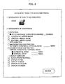
- an icon to be converted is first designated under item 1.
- the icon to be converted is selected from options of unconverted icons on an icon list, not shown, based upon an icon definition data for the patent icon (accumulation of icon data) of the icon data storage area.
- the selected icon is displayed under item 1 as shown by the example in the figure.
- Rotation angle is further designated.
- counterclockwise angle is designated on a one-degree basis in a range of from 1 degree to 359 degrees, and an execution key is pressed (clicked or the like; the same shall apply hereinafter).
- the CPU (see FIG. 1) 11 implements rotation conversion processing by using a required portion of the program data stored in the storage area for program data of icon data conversions (portion required for the rotation conversion processing). Since the processing of rotating a graphic is well known per se, details will be omitted.
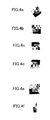
- icon data indicating the icon selected in FIG. 3 is converted into icon data indicating an icon shown in FIG. 4a.
- the converted icon data is stored in the temporary storage area for work data for displaying icon.
- the icon display program stored in the storage area for icon display program data displays a converted icon in the icon display area (for example, bottom of the frame) on the display.
- Conversion contents (label data for designating an unconverted icon, code data indicating "rotation”, data of rotation angle, label data for designating a converted icon, date and time of execution of conversion, etc.) are stored in the storage area for icon definition data for the child icons.
- the label data for designating each of the icons is referred to as "icon ID" for definition.
- the converted icon data is stored in the temporary storage area for work data for displaying icon.
- the icon display program stored in the storage area for icon display program data displays the converted icon in the icon display area (for example, bottom of the frame) on the display.
- Conversion contents (the icon ID for designating the unconverted icon, code data indicating "horizontal conversion", the icon ID for designating the converted icon, date and time of execution of conversion, etc.) are stored in the storage area for icon definition data for the child icons.
- conversion processing for vertical mirror image is executed. Since the processing of making vertical image of a graphic object is well known per se, details will be omitted.
- the icon selected in FIG. 3 is converted into an icon shown in FIG. 4c.
- the subsequent processing is the same as in the case of "horizontal mirror image", so that it will not be repeated again.
- the data stored in the storage area for icon definition data for the child icons includes the icon ID for designating the unconverted icon, code data indicating "vertical conversion", the icon ID for designating the converted icon, and date and time of execution of conversion, etc.
- conversion processing for horizontal-and-vertical mirror image is executed. Since the processing of making horizontal-and-vertical mirror image of a graphic object is well known per se, details will be omitted.
- the icon selected in FIG. 3 is converted into an icon shown in FIG. 4d.
- the subsequent processing is the same as in the case of "horizontal mirror image", so that it will not be repeated again.
- the data stored in the storage area for icon definition data for the child icons includes the icon ID for designating the unconverted icon, code data indicating "horizontal-and-vertical mirror image conversion", the icon ID for designating the converted icon, date and time of execution of conversion, etc.
- a degree of magnification/contraction retaining vertical/horizontal ratio is designated.
- the degree is designated, for example, on a 0.1-time basis in a range of from 0.1 times to 0.9 times (contraction) or from 1.1 times to 3.0 times (magnification), and the execution key is then pressed (1.0 times extraction or contraction is rejected from being designated).
- the CPU (see FIG. 1) 11 implements the rotation conversion processing by using a required portion of the program data that is stored in the storage area for program data of icon data conversions (required for the magnification/contraction processing retaining horizontal/vertical ratio). Since the processing of magnifying/contracting a graphic object retaining horizontal/vertical ratio is well known per se, details will be omitted.
- the icon selected in FIG. 3 is converted into an icon that is magnified by 1.2 times both vertically and horizontally as shown in FIG. 4e.
- the subsequent processing is the same as in the cases of the foregoing conversions, so that it will not be repeated.
- the data stored in the storage area for icon definition data for the child icons includes the icon ID for designating the unconverted icon, code data indicating "magnification/contraction retaining horizontal/vertical ratio", data indicating the degree of the magnification/contraction retaining horizontal/vertical ratio, the icon ID for designating the converted icon, date and time of execution of conversion, etc.
- horizontal and vertical ratios are designated.
- the CPU (see FIG. 1) 11 implements the rotation conversion processing by using a required portion of the program data stored in the storage area for program data of icon data conversions (required for the magnification/contraction processing varying horizontal/vertical ratio). Since the processing of magnifying/contracting a graphic object varying horizontal/vertical ratio is well known per se, details will be omitted.
- the icon selected in FIG. 3 is converted into an icon reduced in horizontal size by 0.5 times and increased in vertical size by 1.5 times as shown in FIG. 4f.
- the subsequent processing is the same as in the cases of the foregoing conversions, so that it will not be repeated.
- the data stored in the storage area for icon definition data for the child icon includes the icon ID for designating the unconverted icon, code data indicating "magnification/contraction conversion varying horizontal/vertical ratio", data indicating the vertical and horizontal ratios, the icon ID for designating the converted icon, date and time of execution of conversion, etc.
- the selected conversion processing is executed.
- the processing of applying the black/white reversal or display in a certain color to the display color of a graphic is well known per se, so that details will be omitted. Illustration of a concrete example before and after conversion will be omitted.
- the designated icon is converted into an icon subjected to the designated color variation (black/white reversal or display in red, blue, yellow or green).
- the subsequent processing is the same as the cases described above, so that it will not be repeated.
- the data stored in the storage area for icon definition data for the child icon includes the icon ID for designating the unconverted icon, code data indicating the "designated color variation (any one of black/white reversal and display in red, blue, yellow and green)", the icon ID for designating the converted icon, date and time of execution of conversion, etc.
- the icon ID for designating the converted icon may be created by the operator on the screen or may be automatically created by a proper program. For instance, one idea is to label with ED ij a j-th icon that is created by carrying out a conversion of an i-th icon ED i previously prepared in the icon data storage area.
- the storage of the converted icon can be substituted with the storage of data of the conversion content, and simply requires a storage capacity that is still smaller than the storage of icon data expressing a pattern of the converted icon. Consequently, even if a large number of icons are created by conversion, and the data of conversion contents is stored, the memory is not applied with major load.
- icons to be displayed are often determined with respect to each frame.
- icons are displayed in a form where a frame A displays icons (illustration of patterns is omitted) corresponding to icon display areas (hereinafter, also simply referred to as "areas") F 1 to F8 in the respective areas; another frame B displays icons corresponding to areas G1 to G8 in the respective areas; and still another frame C displays icons corresponding to areas H1 to H6 in the respective areas.
- the conventional icon data icon definition data capable of expressing patterns
- icon family a group of icons having the above-mentioned analogous relationship with each other even if the icons are not identical, as to the other icons that belong to the same icon family, it is possible to substitute data containing a small amount of information.
- an icon for which the conventional icon definition data is previously prepared is referred to as "parent icon”, and an icon created by converting the "parent icon” through any one of the foregoing conversions is referred to as "child icon”.
- each child icon it is possible to store a conversion content (data for designating an icon ID of the parent icon corresponding to the child icon and the conversion content (classification code of the conversion, a parameter for describing the conversion content; for example, rotation angle if the conversion content is rotation), an icon ID for designating the child icon, etc.) in the storage area for icon definition data for the child icon.
- a conversion content data for designating an icon ID of the parent icon corresponding to the child icon and the conversion content (classification code of the conversion, a parameter for describing the conversion content; for example, rotation angle if the conversion content is rotation), an icon ID for designating the child icon, etc.
- the child icon ED302 if the code data indicating the "horizontal conversion" and the icon ID (ED3) for designating the parent icon are stored in the storage area for icon definition data for the child icon according to the above-described procedure (data input on screen), they can be used as definition data for displaying icons in the areas G6 and H2.
- the child icon ED305 if the code data indicating the "magnification/contraction retaining horizontal/vertical ratio" and the parameter 1.2 indicating the ratio, and the icon ID (ED3) for designating the parent icon are stored in the storage area for icon definition data for the child icon according to the foregoing procedure (data input on screen), it can be used as definition data for indicating the icons G7 and H3. As to the rest of the icons, conventional definition data is previously stored in the icon data storage area (see FIG. 2).
- the definition data (pattern expression data) of ED 11, ED 16, ED 17, ED 18 and ED 19 may be read out and displayed by using the icon display program.
- the definition data (pattern expression data) of ED 1 may be read out and displayed.
- the definition data of ED302 is read out from the storage area for icon definition data for the child icon.
- the conversion content designated therein horizontal mirror image with respect to ED3
- the program of icon data conversions is activated, and the designated conversion is carried out, to thereby display the icon G6 in the frame B by using the icon display program.
- the definition data of ED305 is read out from the storage area for icon definition data for the child icon.
- the program of icon data conversions is activated to implement the designated conversion, to thereby display the icon G7 in the frame B by using the icon display program.
- the frame C is selected, it is possible to display the icons H1 to H6 according to the same procedure.
- the child icons (ED302, 305 and the like in the example) are created by the operator's (user's) designating the conversion contents through data input on screen.
Landscapes
- Engineering & Computer Science (AREA)
- Human Computer Interaction (AREA)
- Manufacturing & Machinery (AREA)
- Physics & Mathematics (AREA)
- General Physics & Mathematics (AREA)
- Automation & Control Theory (AREA)
- User Interface Of Digital Computer (AREA)
- Numerical Control (AREA)
Applications Claiming Priority (1)
| Application Number | Priority Date | Filing Date | Title |
|---|---|---|---|
| JP2006039547A JP2007219830A (ja) | 2006-02-16 | 2006-02-16 | 数値制御装置 |
Publications (1)
| Publication Number | Publication Date |
|---|---|
| EP1821169A2 true EP1821169A2 (de) | 2007-08-22 |
Family
ID=38117074
Family Applications (1)
| Application Number | Title | Priority Date | Filing Date |
|---|---|---|---|
| EP07102452A Withdrawn EP1821169A2 (de) | 2006-02-16 | 2007-02-15 | Numerische Steuerung |
Country Status (4)
| Country | Link |
|---|---|
| US (1) | US20070192707A1 (de) |
| EP (1) | EP1821169A2 (de) |
| JP (1) | JP2007219830A (de) |
| CN (1) | CN101025623A (de) |
Families Citing this family (49)
| Publication number | Priority date | Publication date | Assignee | Title |
|---|---|---|---|---|
| US8225231B2 (en) | 2005-08-30 | 2012-07-17 | Microsoft Corporation | Aggregation of PC settings |
| US20100107100A1 (en) * | 2008-10-23 | 2010-04-29 | Schneekloth Jason S | Mobile Device Style Abstraction |
| US8385952B2 (en) | 2008-10-23 | 2013-02-26 | Microsoft Corporation | Mobile communications device user interface |
| US8411046B2 (en) | 2008-10-23 | 2013-04-02 | Microsoft Corporation | Column organization of content |
| CN101750999B (zh) * | 2008-11-28 | 2012-04-11 | 兄弟工业株式会社 | 机床的显示装置 |
| JP4620156B2 (ja) * | 2009-03-11 | 2011-01-26 | ファナック株式会社 | 軸の再構成機能を有する数値制御装置 |
| US8175653B2 (en) | 2009-03-30 | 2012-05-08 | Microsoft Corporation | Chromeless user interface |
| US8355698B2 (en) | 2009-03-30 | 2013-01-15 | Microsoft Corporation | Unlock screen |
| US8238876B2 (en) | 2009-03-30 | 2012-08-07 | Microsoft Corporation | Notifications |
| US8269736B2 (en) | 2009-05-22 | 2012-09-18 | Microsoft Corporation | Drop target gestures |
| US8836648B2 (en) | 2009-05-27 | 2014-09-16 | Microsoft Corporation | Touch pull-in gesture |
| JP4814365B2 (ja) * | 2009-10-20 | 2011-11-16 | ファナック株式会社 | 加工プログラムやバイナリデータが記憶されているメモリの領域を分割・結合することが可能な数値制御装置 |
| WO2011089913A1 (ja) * | 2010-01-25 | 2011-07-28 | 株式会社日立ハイテクノロジーズ | 走査型電子顕微鏡 |
| US20120159395A1 (en) | 2010-12-20 | 2012-06-21 | Microsoft Corporation | Application-launching interface for multiple modes |
| US20120159383A1 (en) | 2010-12-20 | 2012-06-21 | Microsoft Corporation | Customization of an immersive environment |
| US8689123B2 (en) | 2010-12-23 | 2014-04-01 | Microsoft Corporation | Application reporting in an application-selectable user interface |
| US8612874B2 (en) | 2010-12-23 | 2013-12-17 | Microsoft Corporation | Presenting an application change through a tile |
| US9423951B2 (en) | 2010-12-31 | 2016-08-23 | Microsoft Technology Licensing, Llc | Content-based snap point |
| US9383917B2 (en) | 2011-03-28 | 2016-07-05 | Microsoft Technology Licensing, Llc | Predictive tiling |
| US9104440B2 (en) | 2011-05-27 | 2015-08-11 | Microsoft Technology Licensing, Llc | Multi-application environment |
| US9658766B2 (en) | 2011-05-27 | 2017-05-23 | Microsoft Technology Licensing, Llc | Edge gesture |
| US20120304132A1 (en) | 2011-05-27 | 2012-11-29 | Chaitanya Dev Sareen | Switching back to a previously-interacted-with application |
| US8893033B2 (en) | 2011-05-27 | 2014-11-18 | Microsoft Corporation | Application notifications |
| US9158445B2 (en) | 2011-05-27 | 2015-10-13 | Microsoft Technology Licensing, Llc | Managing an immersive interface in a multi-application immersive environment |
| US9104307B2 (en) | 2011-05-27 | 2015-08-11 | Microsoft Technology Licensing, Llc | Multi-application environment |
| US8687023B2 (en) | 2011-08-02 | 2014-04-01 | Microsoft Corporation | Cross-slide gesture to select and rearrange |
| US20130057587A1 (en) | 2011-09-01 | 2013-03-07 | Microsoft Corporation | Arranging tiles |
| US8922575B2 (en) | 2011-09-09 | 2014-12-30 | Microsoft Corporation | Tile cache |
| US9557909B2 (en) | 2011-09-09 | 2017-01-31 | Microsoft Technology Licensing, Llc | Semantic zoom linguistic helpers |
| US10353566B2 (en) | 2011-09-09 | 2019-07-16 | Microsoft Technology Licensing, Llc | Semantic zoom animations |
| US9244802B2 (en) | 2011-09-10 | 2016-01-26 | Microsoft Technology Licensing, Llc | Resource user interface |
| US8933952B2 (en) | 2011-09-10 | 2015-01-13 | Microsoft Corporation | Pre-rendering new content for an application-selectable user interface |
| US9146670B2 (en) | 2011-09-10 | 2015-09-29 | Microsoft Technology Licensing, Llc | Progressively indicating new content in an application-selectable user interface |
| US9223472B2 (en) | 2011-12-22 | 2015-12-29 | Microsoft Technology Licensing, Llc | Closing applications |
| US9128605B2 (en) | 2012-02-16 | 2015-09-08 | Microsoft Technology Licensing, Llc | Thumbnail-image selection of applications |
| CN103135987A (zh) | 2013-02-22 | 2013-06-05 | 北京小米科技有限责任公司 | 一种动态图标显示方法及装置 |
| US9450952B2 (en) | 2013-05-29 | 2016-09-20 | Microsoft Technology Licensing, Llc | Live tiles without application-code execution |
| EP3126969A4 (de) | 2014-04-04 | 2017-04-12 | Microsoft Technology Licensing, LLC | Erweiterbare anwendungsdarstellung |
| EP3129847A4 (de) | 2014-04-10 | 2017-04-19 | Microsoft Technology Licensing, LLC | Schiebeabdeckung für computervorrichtung |
| KR102107275B1 (ko) | 2014-04-10 | 2020-05-06 | 마이크로소프트 테크놀로지 라이센싱, 엘엘씨 | 컴퓨팅 디바이스에 대한 접이식 쉘 커버 |
| US10254942B2 (en) | 2014-07-31 | 2019-04-09 | Microsoft Technology Licensing, Llc | Adaptive sizing and positioning of application windows |
| US10592080B2 (en) | 2014-07-31 | 2020-03-17 | Microsoft Technology Licensing, Llc | Assisted presentation of application windows |
| US10678412B2 (en) | 2014-07-31 | 2020-06-09 | Microsoft Technology Licensing, Llc | Dynamic joint dividers for application windows |
| US10642365B2 (en) | 2014-09-09 | 2020-05-05 | Microsoft Technology Licensing, Llc | Parametric inertia and APIs |
| WO2016065568A1 (en) | 2014-10-30 | 2016-05-06 | Microsoft Technology Licensing, Llc | Multi-configuration input device |
| US10029366B2 (en) * | 2014-11-21 | 2018-07-24 | Canon Kabushiki Kaisha | Control device for motor drive device, control device for multi-axial motor, and control method for motor drive device |
| KR101873655B1 (ko) * | 2016-11-30 | 2018-07-02 | 엘에스산전 주식회사 | 모니터링 화면 표시 방법 |
| CN111459362A (zh) * | 2020-03-31 | 2020-07-28 | 维沃移动通信有限公司 | 信息显示方法、信息显示装置、电子设备及存储介质 |
| WO2022082447A1 (en) * | 2020-10-20 | 2022-04-28 | Lenovo (Beijing) Limited | Method and apparatus for task management in next generation networks |
Family Cites Families (2)
| Publication number | Priority date | Publication date | Assignee | Title |
|---|---|---|---|---|
| US5931160A (en) * | 1995-12-08 | 1999-08-03 | Cardiopulmonary Corporation | Ventilator control system and method |
| DE10308816A1 (de) * | 2003-02-27 | 2004-05-19 | Siemens Ag | Ikone und Schrittikonendarstellung zur graphischen Visualisierung von aufgabenorientierten Schritten |
-
2006
- 2006-02-16 JP JP2006039547A patent/JP2007219830A/ja active Pending
-
2007
- 2007-02-15 EP EP07102452A patent/EP1821169A2/de not_active Withdrawn
- 2007-02-15 US US11/706,205 patent/US20070192707A1/en not_active Abandoned
- 2007-02-16 CN CNA2007100788448A patent/CN101025623A/zh active Pending
Also Published As
| Publication number | Publication date |
|---|---|
| CN101025623A (zh) | 2007-08-29 |
| JP2007219830A (ja) | 2007-08-30 |
| US20070192707A1 (en) | 2007-08-16 |
Similar Documents
| Publication | Publication Date | Title |
|---|---|---|
| EP1821169A2 (de) | Numerische Steuerung | |
| US11429082B2 (en) | Parameter management apparatus and parameter management system | |
| US20040088119A1 (en) | System for controlling and monitoring machines and/or systems with active components belonging to different active groups | |
| US5327350A (en) | Interactive type numerical control apparatus and method thereof | |
| KR100246862B1 (ko) | 툴 버튼의 설정 방법 및 편집 장치 | |
| US20160062336A1 (en) | Numerical controller for facilitating adjustment of machining motion | |
| CN105938411B (zh) | 控制面板 | |
| JPH08123515A (ja) | シーケンス・プログラムの表示方式 | |
| US7089531B2 (en) | Method and device for generating or editing NC programs | |
| EP4167075B1 (de) | Programmierungsmarkierungsverfahren, prozessor, endgerät und computerprogrammprodukt | |
| US5457369A (en) | Numerical control system | |
| EP0075325B1 (de) | Steuergerät und Verfahren für einen industriellen Roboter | |
| JP5862236B2 (ja) | 制御プログラム編集装置及び制御プログラムの作成支援プログラム | |
| JP6374456B2 (ja) | 電子機器及び数値制御装置 | |
| JP6824454B1 (ja) | 工作システム、工作機械、および、制御プログラム | |
| JP2002312008A (ja) | 数値制御装置 | |
| US20250262766A1 (en) | Robot programming device and programming method | |
| CN116406456A (zh) | 控制装置 | |
| EP1746474A1 (de) | Numerische Steuerung mit integrierter Anzeige für CNC- und Anwendungsprogrammdaten | |
| JP7108156B1 (ja) | 情報生成装置、およびコンピュータ読み取り可能な記憶媒体 | |
| EP0578828A1 (de) | Bildschirmanzeigeverfahren für numerische steuerung | |
| EP1455252A2 (de) | Gerät zur Erzeugung eines Bearbeitungsprogrammes | |
| EP4068020A1 (de) | Anzeigesteuerungssystem | |
| KR102855749B1 (ko) | 공작기계 모니터 화면의 그래픽 기반 이미지 표현 방법 | |
| JPH05346811A (ja) | セルコントローラ |
Legal Events
| Date | Code | Title | Description |
|---|---|---|---|
| PUAI | Public reference made under article 153(3) epc to a published international application that has entered the european phase |
Free format text: ORIGINAL CODE: 0009012 |
|
| AK | Designated contracting states |
Kind code of ref document: A2 Designated state(s): AT BE BG CH CY CZ DE DK EE ES FI FR GB GR HU IE IS IT LI LT LU LV MC NL PL PT RO SE SI SK TR |
|
| AX | Request for extension of the european patent |
Extension state: AL BA HR MK YU |
|
| RIN1 | Information on inventor provided before grant (corrected) |
Inventor name: NAGAYAMA, SUSUMU Inventor name: NAKAMURA, SHINYA,FANUC MANSHONHARIMOMI,3511-1 Inventor name: MAEDA, HIDEAKI,FANUC MANSHONHARIMOMI,3511-1 |
|
| RIN1 | Information on inventor provided before grant (corrected) |
Inventor name: NAGAYAMA, SUSUMU Inventor name: NAKAMURA, SHINYA,FANUC MANSHONHARIMOMI,3511-1 Inventor name: MAEDA, HIDEAKI,FANUC MANSHONHARIMOMI,3511-1 |
|
| STAA | Information on the status of an ep patent application or granted ep patent |
Free format text: STATUS: THE APPLICATION HAS BEEN WITHDRAWN |
|
| 18W | Application withdrawn |
Effective date: 20071121 |