EP1818212A2 - Fahrzeug-Innenausstattung und Einstellverfahren - Google Patents
Fahrzeug-Innenausstattung und Einstellverfahren Download PDFInfo
- Publication number
- EP1818212A2 EP1818212A2 EP07001355A EP07001355A EP1818212A2 EP 1818212 A2 EP1818212 A2 EP 1818212A2 EP 07001355 A EP07001355 A EP 07001355A EP 07001355 A EP07001355 A EP 07001355A EP 1818212 A2 EP1818212 A2 EP 1818212A2
- Authority
- EP
- European Patent Office
- Prior art keywords
- vehicle
- vehicle seat
- tunnel console
- interior
- seat
- Prior art date
- Legal status (The legal status is an assumption and is not a legal conclusion. Google has not performed a legal analysis and makes no representation as to the accuracy of the status listed.)
- Withdrawn
Links
Images



Classifications
-
- B—PERFORMING OPERATIONS; TRANSPORTING
- B60—VEHICLES IN GENERAL
- B60N—SEATS SPECIALLY ADAPTED FOR VEHICLES; VEHICLE PASSENGER ACCOMMODATION NOT OTHERWISE PROVIDED FOR
- B60N2/00—Seats specially adapted for vehicles; Arrangement or mounting of seats in vehicles
- B60N2/02—Seats specially adapted for vehicles; Arrangement or mounting of seats in vehicles the seat or part thereof being movable, e.g. adjustable
- B60N2/04—Seats specially adapted for vehicles; Arrangement or mounting of seats in vehicles the seat or part thereof being movable, e.g. adjustable the whole seat being movable
- B60N2/06—Seats specially adapted for vehicles; Arrangement or mounting of seats in vehicles the seat or part thereof being movable, e.g. adjustable the whole seat being movable slidable
-
- B—PERFORMING OPERATIONS; TRANSPORTING
- B60—VEHICLES IN GENERAL
- B60N—SEATS SPECIALLY ADAPTED FOR VEHICLES; VEHICLE PASSENGER ACCOMMODATION NOT OTHERWISE PROVIDED FOR
- B60N2/00—Seats specially adapted for vehicles; Arrangement or mounting of seats in vehicles
- B60N2/75—Arm-rests
- B60N2/763—Arm-rests adjustable
- B60N2/77—Height adjustment
-
- B—PERFORMING OPERATIONS; TRANSPORTING
- B60—VEHICLES IN GENERAL
- B60N—SEATS SPECIALLY ADAPTED FOR VEHICLES; VEHICLE PASSENGER ACCOMMODATION NOT OTHERWISE PROVIDED FOR
- B60N2/00—Seats specially adapted for vehicles; Arrangement or mounting of seats in vehicles
- B60N2/75—Arm-rests
- B60N2/763—Arm-rests adjustable
- B60N2/773—Longitudinal adjustment
-
- B—PERFORMING OPERATIONS; TRANSPORTING
- B60—VEHICLES IN GENERAL
- B60T—VEHICLE BRAKE CONTROL SYSTEMS OR PARTS THEREOF; BRAKE CONTROL SYSTEMS OR PARTS THEREOF, IN GENERAL; ARRANGEMENT OF BRAKING ELEMENTS ON VEHICLES IN GENERAL; PORTABLE DEVICES FOR PREVENTING UNWANTED MOVEMENT OF VEHICLES; VEHICLE MODIFICATIONS TO FACILITATE COOLING OF BRAKES
- B60T7/00—Brake-action initiating means
- B60T7/02—Brake-action initiating means for personal initiation
- B60T7/08—Brake-action initiating means for personal initiation hand actuated
- B60T7/10—Disposition of hand control
- B60T7/102—Disposition of hand control by means of a tilting lever
Definitions
- the invention relates to an interior trim for a vehicle, in particular for a motor vehicle, comprising a vehicle seat and a tunnel console extending alongside the vehicle seat, in particular the driver's seat, which are arranged to be displaceable at least in parts in the vehicle interior, and a method for setting a special interior.
- a generic interior for a motor vehicle is from the document DE 103 34 999 A1 known.
- the interior comprises front seats and a center or tunnel console arranged between them, which is adjustable in whole or in sections from a front end position to the rear to a rear end position before or between the rear seats.
- the space utilization of the vehicle interior to be improved by this training.
- An adjustment of the seating position has no influence on the position of the tunnel console in the vehicle interior.
- the invention has for its object to improve the coordination of the position of tunnel console and vehicle seat and thus the comfort of the vehicle.
- the object is achieved with an interior of the type mentioned above in that the position of the tunnel console or parts thereof is variable depending on the position of the vehicle seat. This makes it possible to bring about a preset optimized or individually preselected position of the tunnel console and arranged thereon operating or comfort components for each seating position.
- the vehicle seat and the tunnel console are mechanically and / or electrically operatively connected to each other with respect to their positional change in the vehicle and in their position to each other adjustable so that upon a displacement of the vehicle seat a rectified displacement of the tunnel console.
- the position of the tunnel console in the direction of travel (-X direction of the vehicle) and / or in the vertical direction (Z-direction of the vehicle) in dependence on the position of the vehicle seat in the direction of travel and / or vertical Direction is changeable.
- the displacement of the vehicle seat and tunnel console can take place, for example, by the same route, with the vehicle seat and tunnel console being adjustable relative to one another by means of a linear guidance system, in particular a positioning rail.
- the position of the tunnel console in the vertical direction (Z-direction of the vehicle) in dependence on the position of the vehicle seat in the direction of travel (-X direction of the vehicle) is variable.
- the detection of the seat occupant can be done for example by a personal ignition key or a code to be entered by the occupant.
- the setting is preferably carried out by setting and electronically storing a first position of the vehicle seat and a first position of the tunnel console, subsequently setting and electronically storing a second position of the vehicle seat and a second position of the tunnel console, and by retrieving the stored data Tunnel console in each case the previously specified position is assigned relative to the vehicle seat.
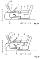
- the vehicle interior 1 shown in FIG. 1 has an interior 2, which in the exemplary embodiment includes a driver's seat 3, a passenger seat 4, a cockpit 5 and a tunnel console 6.
- the tunnel console 6 is equipped with various operating and comfort components, namely with a shift lever 7, the hand brake handle 8, cup holders 9 and an armrest 10, below which there is an accessible after folding the armrest 10 storage compartment 11.
- Shift lever 7 and hand brake handle 8 can be mechanically, but preferably electrically or electromechanically operatively connected to the transmission or brake system.
- Driver's seat 3 and passenger's seat 4 are longitudinally displaceable in the vehicle interior in the direction of travel (-X direction of the vehicle) and counter to the direction of travel (X-direction of the vehicle) and can be adapted to the needs of the respective seat occupant with respect to their longitudinal position.
- the tunnel console 6 is also displaceable in -X or X-direction. While the passenger seat 4 is not operatively connected to the tunnel console 6, the driver's seat 3 can be mechanically coupled thereto by a longitudinally adjustable control rail 12.
- the driver's seat 3 in the functional position according to FIG. 1 b is decoupled in a manner known per se from the tunnel console 6 to the front (-X direction) into another one Use position has been moved (arrow A).
- the stationary armrest 10 is thus located in an unfavorable because too far back arranged position.
- the interior equipment 2 moves out of the position according to FIG. 1a by common displacement and driver console 3 with respect to direction and path such that the position of the armrest 10 relative to the driver's seat 3 remains unchanged remains (arrows A, B in Fig. 1c).
- tunnel console 6 is displaced in its entirety. It is also conceivable to move only the armrest 10 forward (arrow C), while leaving the other components in an unchanged position relative to the steering wheel 13, as shown in Fig. 1d.
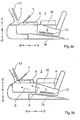
- the driver's seat 3 is further arranged longitudinally adjustable in the vehicle interior 1, the tunnel console 6, however, has an adjustability upwards (Z-direction of the vehicle) and down (-Z-direction of the vehicle) and is connected to the Driver's seat 3 operatively connected by a lever assembly 14.
- a section 15 of the tunnel console 6 is raised by the mechanical coupling (arrow D).
- the driver's seat 3 shown in FIG. 3 is guided on an inclined ramp 16 such that a rearward displacement also results in a displacement of the driver's seat 3 downwards (FIG. 3 a).
- the portion 15 of the tunnel console 6 and the driver's seat 3 are, in their position to each other by the adjusting rail 12 adjustable, so operatively connected to each other, that a displacement of the driver's seat 3 in -X and Z-direction (arrow A) same in terms of displacement and direction displacement the portion 15 of the tunnel console 6 causes (arrow B).
- both the driver's seat 3 and the section 15 of the tunnel console 6 can be adjusted in length and height by drives 17, 17 ', 17'
- a control device 18 is programmable by the seat occupant such that a first sitting position is a first seat position 4b) can be assigned to any other position of the section 15 (FIG. 4b). If the control device 18 recognizes a seat occupant on the basis of a radio signal 20 emanating from the person-specific ignition key 19, they adjust the drives 17. 17 ', 17 ", the portion 15 of the tunnel console 6 and the vehicle seat 3 in the previously determined by the person in question position (arrows A, B). The way and direction of the adjustment movements of section 15 and driver's seat 3 may differ as desired within the scope of the approved adjustment.
Landscapes
- Engineering & Computer Science (AREA)
- Transportation (AREA)
- Mechanical Engineering (AREA)
- Aviation & Aerospace Engineering (AREA)
- Seats For Vehicles (AREA)
- Vehicle Step Arrangements And Article Storage (AREA)
Abstract
Description
- Die Erfindung betrifft eine Innenausstattung für ein Fahrzeug, insbesondere für ein Kraftfahrzeug, mit einem Fahrzeugsitz und einer sich längsseits des Fahrzeugsitzes, insbesondere des Fahrersitzes, erstreckenden Tunnelkonsole, welche zumindest in Teilen im Fahrzeuginnenraum verlagerbar angeordnet sind, sowie ein Verfahren zur Einstellung einer speziellen Innenausstattung.
- Eine gattungsgemäße Innenausstattung für ein Kraftfahrzeug ist aus der Druckschrift
DE 103 34 999 A1 bekannt. Die Innenausstattung umfasst Vordersitze und eine zwischen diesen angeordnete Mittel- oder Tunnelkonsole, welche insgesamt oder in Abschnitten von einer vorderen Endposition nach hinten bis in eine hintere Endposition vor oder zwischen den Rücksitzen verstellbar ist. Die Raumausnutzung des Fahrzeuginnenraums soll durch diese Ausbildung verbessert werden. Eine Einstellung der Sitzposition hat dabei auf die Position der Tunnelkonsole im Fahrzeuginnenraum keinen Einfluss. - Der Erfindung liegt die Aufgabe zugrunde, die Abstimmung der Position von Tunnelkonsole und Fahrzeugsitz und damit den Komfort des Fahrzeugs zu verbessern.
- Die Aufgabe wird bei einer Innenausstattung der eingangs genannten Art dadurch gelöst, dass die Position der Tunnelkonsole oder von Teilen derselben in Abhängigkeit von der Position des Fahrzeugsitzes veränderbar ist. Hierdurch ist es möglich, zu jeder Sitzposition eine vorgegeben optimierte oder individuell vorgewählte Stellung der Tunnelkonsole und darauf angeordneter Bedien- oder Komfortkomponenten herbeizuführen.
- Mit Vorteil sind der Fahrzeugsitz und die Tunnelkonsole dabei mechanisch und/oder elektrisch hinsichtlich ihrer Lageveränderung im Fahrzeug miteinander wirkverbunden und in ihrer Lage zueinander derart einstellbar, dass bei einer Verlagerung des Fahrzeugsitzes eine gleichgerichtete Verlagerung der Tunnelkonsole erfolgt.
- Nach einer Ausführung der Erfindung kann vorgesehen werden, dass die Position der Tunnelkonsole in Fahrtrichtung (-X-Richtung des Fahrzeugs) und/oder in vertikaler Richtung (Z-Richtung des Fahrzeugs) in Abhängigkeit von der Position des Fahrzeugsitzes in Fahrtrichtung und/oder vertikaler Richtung veränderbar ist. Dabei kann die Verlagerung von Fahrzeugsitz und Tunnelkonsole beispielsweise um den gleichen Weg erfolgen, wobei Fahrzeugsitz und Tunnelkonsole mittels eines Linearführungssystems, insbesondere einer Stellschiene, relativ zueinander einstellbar sind.
- Mit besonderem Vorteil ist vorgesehen, dass die Position der Tunnelkonsole in vertikaler Richtung (Z-Richtung des Fahrzeugs) in Abhängigkeit von der Position des Fahrzeugsitzes in Fahrtrichtung (-X-Richtung des Fahrzeugs) veränderbar ist.
- Nach einer besonders bevorzugten Ausführungsform der Erfindung ist wenigstens einer ersten Position des Fahrzeugsitzes oder einem ersten Fahrzeuginsassen eine erste Position der Tunnelkonsole und einer zweiten Position des Fahrzeugsitzes oder einem zweiten Fahrzeuginsassen eine zweite Position der Tunnelkonsole frei wählbar zuweisbar. Die Erkennung des Sitzinsassen kann beispielsweise durch einen personenbezogenen Zündschlüssel oder einen vom Insassen einzugebenden Code erfolgen.
- Die Einstellung erfolgt vorzugsweise dadurch, dass eine erste Position des Fahrzeugsitzes und eine erste Position der Tunnelkonsole eingestellt und elektronisch gespeichert werden, dass nachfolgend eine zweite Position des Fahrzeugsitzes und eine zweite Position der Tunnelkonsole eingestellt und elektronisch gespeichert werden und dass durch Abrufen der gespeicherten Daten der Tunnelkonsole jeweils die zuvor vorgegebene Position relativ zum Fahrzeugsitz zugewiesen wird.
- Die Figuren stellen beispielhaft und schematisch verschiedene Ausführungen der Erfindung dar.
- Es zeigen:
- Fig. 1
- eine Aufsicht auf einen Fahrzeuginnenraum mit einer erfindungsgemäßen Innenausstattung in verschiedenen Funktionsstellungen,
- Fig. 2 bis 4
- seitliche Ansichten von Innenausstattungen nach anderen Ausbildungen der Erfindung.
- Der in Fig. 1 dargestellte Fahrzeuginnenraum 1 weist eine Innenausstattung 2 auf, die im Ausführungsbeispiel einen Fahrersitz 3, einen Beifahrersitz 4, ein Cockpit 5 und eine Tunnelkonsole 6 umfasst. Die Tunnelkonsole 6 ist mit verschiedenen Bedien- und Komfortkomponenten ausgestattet, nämlich mit einem Schalthebel 7, dem Handbremsgriff 8, Getränkehaltern 9 und einer Armauflage 10, unterhalb derer sich ein nach dem Hochklappen der Armauflage 10 zugängliches Staufach 11 befindet. Schalthebel 7 und Handbremsgriff 8 können mechanisch, vorzugsweise aber elektrisch oder elektromechanisch mit Getriebe bzw. Bremsanlage wirkverbunden sein.
- Fahrersitz 3 und Beifahrersitz 4 sind in Fahrtrichtung (-X-Richtung des Fahrzeugs) sowie entgegen der Fahrtrichtung (X-Richtung des Fahrzeugs) längsverschieblich im Fahrzeuginnenraum angeordnet und können bezüglich ihrer Längsposition an die Bedürfnisse der jeweiligen Sitzinsassen angepasst werden. Auch die Tunnelkonsole 6 ist in -X bzw. X-Richtung verlagerbar. Während der Beifahrersitz 4 nicht mit der Tunnelkonsole 6 wirkverbunden ist, ist der Fahrersitz 3 mit dieser mechanisch durch eine längseinstellbare Stellschiene 12 koppelbar.
- Aus der ersten Funktionsstellung nach Fig. 1a ist der Fahrersitz 3 in der Funktionsstellung nach Fig. 1 b in an sich bekannter Weise von der Tunnelkonsole 6 entkoppelt nach vorne (-X-Richtung) in eine andere Gebrauchsstellung verschoben worden (Pfeil A). Die ortsfest gebliebene Armauflage 10 befindet sich hierdurch in einer ungünstigen, da zu weit hinten angeordneten, Position.
- Werden Fahrersitz 3 und Tunnelkonsole 6 hingegen miteinander gekoppelt, verstellt sich die Innenausstattung 2 aus der Stellung nach Fig. 1a durch gemeinsames, hinsichtlich Richtung und Weg gleichartiges Verschieben von Fahrersitz 3 und Tunnelkonsole 6 derart, dass die Position der Armauflage 10 relativ zum Fahrersitz 3 unverändert bleibt (Pfeile A, B in Fig. 1c).
- Selbstverständlich ist es nicht erforderlich, dass die Tunnelkonsole 6 in ihrer Gesamtheit verlagert wird. Ebenso ist denkbar, nur die Armauflage 10 nach vorne zu verschieben (Pfeil C), die übrigen Komponenten hingegen in einer unveränderten Lage relativ zum Lenkrad 13 zu belassen, wie in Fig. 1d gezeigt.
- Bei der Ausführung nach Fig. 2 ist der Fahrersitz 3 weiterhin längsverstellbar im Fahrzeuginnenraum 1 angeordnet, die Tunnelkonsole 6 hingegen weist eine Verstellbarkeit nach oben (Z-Richtung des Fahrzeugs) sowie nach unten (-Z-Richtung des Fahrzeugs) auf und ist mit dem Fahrersitz 3 durch eine Hebelanordnung 14 wirkverbunden. Bei einer Verschiebung des Fahrersitzes 3 aus einer hinteren Stellung (Fig. 2a) in eine vordere Stellung (Fig. 2b) in Richtung des Pfeils A wird durch die mechanische Kopplung ein Teilstück 15 der Tunnelkonsole 6 angehoben (Pfeil D).
- Der in Fig. 3 gezeigte Fahrersitz 3 ist auf einer schräg gestellten Rampe 16 derart geführt, dass eine nach hinten gerichtete Verschiebung auch eine Verlagerung des Fahrersitzes 3 nach unten zur Folge hat (Fig. 3a). Damit wird dem Umstand Rechnung getragen, dass ein Fahrer mit langen Beinen üblicherweise auch einen großen Oberkörper hat. Das Teilstück 15 der Tunnelkonsole 6 und der Fahrersitz 3 sind, in ihrer Lage zueinander durch die Stellschiene 12 einstellbar, so miteinander wirkverbunden, dass eine Verschiebung des Fahrersitzes 3 in -X und Z-Richtung (Pfeil A) eine hinsichtlich Weg und Richtung gleiche Verlagerung des Teilstücks 15 der Tunnelkonsole 6 bewirkt (Pfeil B).
- Bei der Innenausstattung 2 nach Fig. 4 sind sowohl Fahrersitz 3 als auch das Teilstück 15 der Tunnelkonsole 6 durch Antriebe 17, 17', 17" längs- und höhenverstellbar. Ein Steuergerät 18 ist dabei vom Sitzinsassen so programmierbar, dass einer ersten Sitzstellung eine erste Position des Teilstücks 15 (Fig. 4a) und einer anderen Sitzstellung eine beliebige weitere Position des Teilstücks 15 (Fig. 4b) zugewiesen werden kann. Erkennt das Steuergerät 18 aufgrund eines vom personenspezifischen Zündschlüssel 19 ausgehenden Funksignals 20 einen Sitzinsassen, verstellen die Antriebe 17, 17', 17" das Teilstück 15 der Tunnelkonsole 6 sowie den Fahrzeugsitz 3 in die zuvor von der betreffenden Person bestimmte Stellung (Pfeile A, B). Weg und Richtung der Verstellbewegungen von Teilstück 15 und Fahrersitz 3 können dabei im Rahmen der zugelassenen Verstellmöglichkeiten beliebig voneinander abweichen.
-
- 1
- Fahrzeuginnenraum
- 2
- Innenausstattung
- 3
- Fahrersitz
- 4
- Beifahrersitz
- 5
- Cockpit
- 6
- Tunnelkonsole
- 7
- Schalthebel
- 8
- Handbremsgriff
- 9
- Getränkehalter
- 10
- Armauflage
- 11
- Staufach
- 12
- Stellschiene
- 13
- Lenkrad
- 14
- Hebelanordnung
- 15
- Teilstück (der Tunnelkonsole)
- 16
- Rampe
- 17
- Antrieb
- 18
- Steuergerät
- 19
- Zündschlüssel
- 20
- Funksignal
Claims (10)
Applications Claiming Priority (1)
| Application Number | Priority Date | Filing Date | Title |
|---|---|---|---|
| DE102006005951A DE102006005951B3 (de) | 2006-02-09 | 2006-02-09 | Fahrzeug-Innenausstattung mit mindestens einem Fahrzeugsitz und einer Tunnelkonsole |
Publications (2)
| Publication Number | Publication Date |
|---|---|
| EP1818212A2 true EP1818212A2 (de) | 2007-08-15 |
| EP1818212A3 EP1818212A3 (de) | 2010-02-03 |
Family
ID=38024122
Family Applications (1)
| Application Number | Title | Priority Date | Filing Date |
|---|---|---|---|
| EP07001355A Withdrawn EP1818212A3 (de) | 2006-02-09 | 2007-01-23 | Fahrzeug-Innenausstattung und Einstellverfahren |
Country Status (2)
| Country | Link |
|---|---|
| EP (1) | EP1818212A3 (de) |
| DE (1) | DE102006005951B3 (de) |
Cited By (3)
| Publication number | Priority date | Publication date | Assignee | Title |
|---|---|---|---|---|
| CN111196185A (zh) * | 2018-11-16 | 2020-05-26 | 现代坦迪斯株式会社 | 自主驾驶车辆的移动控制台控制系统及方法 |
| US11958440B2 (en) | 2018-07-10 | 2024-04-16 | Shanghai Yanfeng Jinqiao Automotive Trim Systems Co. Ltd. | Vehicle interior component |
| EP4210996B1 (de) * | 2020-09-08 | 2025-03-26 | Brose Fahrzeugteile SE & Co. Kommanditgesellschaft, Bamberg | Innenraumverstellsystem für ein fahrzeug |
Families Citing this family (6)
| Publication number | Priority date | Publication date | Assignee | Title |
|---|---|---|---|---|
| US10011240B1 (en) | 2016-12-12 | 2018-07-03 | Ford Global Technologies, Llc | Vehicle console with coupled motion and enhanced storage capabilities |
| US10377317B2 (en) * | 2016-12-12 | 2019-08-13 | Ford Global Technologies, Llc | Vehicle console with coupled motion and enhanced storage capabilities |
| DE102017007418B4 (de) * | 2017-08-05 | 2021-11-04 | Audi Ag | Kraftfahrzeug mit wenigstens einem Fahrzeugsitz |
| DE102018212977A1 (de) * | 2018-08-02 | 2020-02-06 | Faurecia Innenraum Systeme Gmbh | Kraftfahrzeugbelüftungssystem zum Leiten von Frontalluft basierend auf der Sitzbewegung beim autonomen Fahren |
| DE102019201485B4 (de) | 2019-02-06 | 2023-12-28 | Psa Automobiles Sa | Verstellanordnung und Verfahren zur Verstellung mindestens eines Fahrzeugsitzes eines Fahrzeugs und Fahrzeug mit der Verstellanordnung |
| DE102023002704A1 (de) | 2023-07-03 | 2024-04-18 | Mercedes-Benz Group AG | Mittelkonsole für einen Kraftwagen sowie Verfahren |
Family Cites Families (4)
| Publication number | Priority date | Publication date | Assignee | Title |
|---|---|---|---|---|
| DE1925377A1 (de) * | 1969-05-19 | 1970-11-26 | Artur Fischer | Aus Fahrbahnabschnitten zusammensetzbare Spielzeugfahrbahnanlage |
| JP3785944B2 (ja) * | 2001-03-30 | 2006-06-14 | 日産自動車株式会社 | 車両用の操作部配置構造 |
| DE10202578A1 (de) * | 2002-01-24 | 2003-08-07 | Daimler Chrysler Ag | Vorrichtung zur Ablage von Gegenständen für ein Kraftfahrzeug |
| DE10334999A1 (de) * | 2003-07-31 | 2005-02-24 | Bayerische Motoren Werke Ag | Fahrzeug |
-
2006
- 2006-02-09 DE DE102006005951A patent/DE102006005951B3/de not_active Expired - Fee Related
-
2007
- 2007-01-23 EP EP07001355A patent/EP1818212A3/de not_active Withdrawn
Cited By (4)
| Publication number | Priority date | Publication date | Assignee | Title |
|---|---|---|---|---|
| US11958440B2 (en) | 2018-07-10 | 2024-04-16 | Shanghai Yanfeng Jinqiao Automotive Trim Systems Co. Ltd. | Vehicle interior component |
| CN111196185A (zh) * | 2018-11-16 | 2020-05-26 | 现代坦迪斯株式会社 | 自主驾驶车辆的移动控制台控制系统及方法 |
| US11505094B2 (en) | 2018-11-16 | 2022-11-22 | Hyundai Transys Inc. | System and method for controlling moving console of self-driving vehicle |
| EP4210996B1 (de) * | 2020-09-08 | 2025-03-26 | Brose Fahrzeugteile SE & Co. Kommanditgesellschaft, Bamberg | Innenraumverstellsystem für ein fahrzeug |
Also Published As
| Publication number | Publication date |
|---|---|
| EP1818212A3 (de) | 2010-02-03 |
| DE102006005951B3 (de) | 2007-10-04 |
Similar Documents
| Publication | Publication Date | Title |
|---|---|---|
| EP1818212A2 (de) | Fahrzeug-Innenausstattung und Einstellverfahren | |
| DE102009033797A1 (de) | Sitzanlage für den Innenraum eines Kraftwagens | |
| DE102019112875A1 (de) | Lenksystem eines Fahrzeuges und Verfahren zum Betrieb eines Lenksystems eines Fahrzeuges | |
| DE102007062573A1 (de) | Sitzanordnung in einer Fahrgastzelle eines Kraftwagens | |
| DE102019001066A1 (de) | Sitzanlage für einen lnnenraum eines Kraftwagens | |
| DE102012019485A1 (de) | Komfortsitz für ein Kraftfahrzeug | |
| DE102007062581A1 (de) | Fahrzeugsitzanordnung für einen Kraftwagen | |
| DE10317901B3 (de) | Mittelkonsole für ein Kraftfahrzeug | |
| EP3837133B1 (de) | Mittelkonsole und kraftfahrzeug | |
| DE19649149B4 (de) | Verfahren zum Einstellen einer Fahrzeugsitzkomponente | |
| DE10353403B4 (de) | Verstellschalteranordnung zur Einstellung eines Kraftfahrzeugsitzes, insbesondere Joystickverstellung | |
| DE19922645A1 (de) | Vorrichtung zum manuellen und/oder automatischen Verstellen eines mehrere Sitzelemente aufweisenden Fahrzeugsitzes | |
| DE3910778A1 (de) | Verfahren zur steuerung von der sitzverstellung zugeordneten stellvorrichtungen eines kraftfahrzeugsitzes | |
| DE4400934C1 (de) | Kraftwagen | |
| DE102016015269A1 (de) | Fahrzeugsitz | |
| DE102024001112A1 (de) | Fußstütze für einen Fondbereich eines Fahrzeuges | |
| DE102023001990A1 (de) | Mittelkonsolen-Armauflagen-Einrichtung für einen Personenkraftwagen | |
| DE102020119360B4 (de) | Erweiterter Sitzverstellbereich für autonome Fahrfunktionen | |
| DE102019210332B4 (de) | Vorrichtung zur Verstellung einer Pedalanordnung | |
| DE102009059837A1 (de) | Fahrzeugsitz | |
| DE102018106345B4 (de) | Kraftfahrzeug | |
| DE102017206414A1 (de) | Bedienvorrichtung für ein Kraftfahrzeug und Verfahren zum Betreiben eines Kraftfahrzeugs mittels einer Bedienvorrichtung | |
| EP1331136A1 (de) | Verstellbare Mittel-Ablagebehälter mit Getriebeschaltelement | |
| DE102016201985A1 (de) | Flexible Stauraumanordnung | |
| DE102016215059A1 (de) | Fahrerlebnis-Einstellsystem sowie Verfahren zum Betreiben eines Fahrerlebnis-Einstellsystems sowie Fahrdynamikeinstellsystem |
Legal Events
| Date | Code | Title | Description |
|---|---|---|---|
| PUAI | Public reference made under article 153(3) epc to a published international application that has entered the european phase |
Free format text: ORIGINAL CODE: 0009012 |
|
| AK | Designated contracting states |
Kind code of ref document: A2 Designated state(s): AT BE BG CH CY CZ DE DK EE ES FI FR GB GR HU IE IS IT LI LT LU LV MC NL PL PT RO SE SI SK TR |
|
| AX | Request for extension of the european patent |
Extension state: AL BA HR MK RS |
|
| PUAL | Search report despatched |
Free format text: ORIGINAL CODE: 0009013 |
|
| AK | Designated contracting states |
Kind code of ref document: A3 Designated state(s): AT BE BG CH CY CZ DE DK EE ES FI FR GB GR HU IE IS IT LI LT LU LV MC NL PL PT RO SE SI SK TR |
|
| AX | Request for extension of the european patent |
Extension state: AL BA HR MK RS |
|
| 17P | Request for examination filed |
Effective date: 20100803 |
|
| 17Q | First examination report despatched |
Effective date: 20100825 |
|
| AKX | Designation fees paid |
Designated state(s): AT BE BG CH CY CZ DE DK EE ES FI FR GB GR HU IE IS IT LI LT LU LV MC NL PL PT RO SE SI SK TR |
|
| GRAP | Despatch of communication of intention to grant a patent |
Free format text: ORIGINAL CODE: EPIDOSNIGR1 |
|
| INTG | Intention to grant announced |
Effective date: 20150303 |
|
| STAA | Information on the status of an ep patent application or granted ep patent |
Free format text: STATUS: THE APPLICATION IS DEEMED TO BE WITHDRAWN |
|
| 18D | Application deemed to be withdrawn |
Effective date: 20150714 |