EP1817251B1 - Safety device for use in an elevator system - Google Patents
Safety device for use in an elevator system Download PDFInfo
- Publication number
- EP1817251B1 EP1817251B1 EP04813071.0A EP04813071A EP1817251B1 EP 1817251 B1 EP1817251 B1 EP 1817251B1 EP 04813071 A EP04813071 A EP 04813071A EP 1817251 B1 EP1817251 B1 EP 1817251B1
- Authority
- EP
- European Patent Office
- Prior art keywords
- triggering member
- elevator car
- actuator
- elevator
- triggering
- Prior art date
- Legal status (The legal status is an assumption and is not a legal conclusion. Google has not performed a legal analysis and makes no representation as to the accuracy of the status listed.)
- Not-in-force
Links
- 238000007689 inspection Methods 0.000 claims description 9
- 238000013459 approach Methods 0.000 claims 1
- 238000000034 method Methods 0.000 description 6
- 238000012423 maintenance Methods 0.000 description 4
- 230000003993 interaction Effects 0.000 description 2
- 230000003213 activating effect Effects 0.000 description 1
- 230000009286 beneficial effect Effects 0.000 description 1
- 230000000903 blocking effect Effects 0.000 description 1
- 230000007423 decrease Effects 0.000 description 1
- 230000000694 effects Effects 0.000 description 1
- 230000002452 interceptive effect Effects 0.000 description 1
- 238000012986 modification Methods 0.000 description 1
- 230000004048 modification Effects 0.000 description 1
- 230000007935 neutral effect Effects 0.000 description 1
Images


Classifications
-
- B—PERFORMING OPERATIONS; TRANSPORTING
- B66—HOISTING; LIFTING; HAULING
- B66B—ELEVATORS; ESCALATORS OR MOVING WALKWAYS
- B66B5/00—Applications of checking, fault-correcting, or safety devices in elevators
- B66B5/0043—Devices enhancing safety during maintenance
- B66B5/005—Safety of maintenance personnel
- B66B5/0056—Safety of maintenance personnel by preventing crushing
- B66B5/0068—Safety of maintenance personnel by preventing crushing by activating the safety brakes when the elevator car exceeds a certain upper or lower position in the elevator shaft
-
- B—PERFORMING OPERATIONS; TRANSPORTING
- B66—HOISTING; LIFTING; HAULING
- B66B—ELEVATORS; ESCALATORS OR MOVING WALKWAYS
- B66B5/00—Applications of checking, fault-correcting, or safety devices in elevators
- B66B5/02—Applications of checking, fault-correcting, or safety devices in elevators responsive to abnormal operating conditions
- B66B5/04—Applications of checking, fault-correcting, or safety devices in elevators responsive to abnormal operating conditions for detecting excessive speed
- B66B5/06—Applications of checking, fault-correcting, or safety devices in elevators responsive to abnormal operating conditions for detecting excessive speed electrical
Definitions
- This invention generally relates to elevator systems. More particularly, this invention relates to a safety device for use in an elevator system.
- Contemporary elevator systems include an elevator car that moves within a hoistway between different levels in a building, for example.
- Various safety considerations are taken into account and various devices are provided for such considerations.
- some elevator systems allow the elevator car to move within the hoistway such that there is limited overhead clearance when the car is in its highest position.
- This low-overhead feature of such systems presents a challenge during maintenance procedures, for example.
- a mechanic or technician must enter the hoistway and be on top of the car to service elevator equipment, for example. It is important to ensure adequate clearance between the elevator car and the ends of the hoistway during such a maintenance procedure.
- Known systems include placing the controller of the elevator into a service mode, which typically includes a limited range of motion for the elevator car. Electrical safety switches have been proposed as a redundant measure for an event where a control system would not operate correctly during a maintenance procedure.
- a physical blocking mechanism such as sliding bolts or moveable columns positioned on top of a car or in an elevator pit that can be manually moved into position to block the car from moving too close to an end of the hoistway.
- EP 1 422 182 A1 discloses a mechanism for activating the parachute in an elevator with reduced pit, when the distance between the bottom of the elevator car and the bottom of the pit decreases under a minimum safety value, wherein the operation of releasing and/or retracting said mechanism is made by a remote manual operation, performable from outside the elevator shaft.
- a device actuator fixedly secured to a guide through a rotation pin, is in a released position, as long as a spring, guided by a pin, is not compressed.
- a needle of the parachute safety device mounted under the elevator arcade remains in the neutral position, until the elevator, in inspection motion, doesn't reach the safety distance, when the actuator interacts with the rod causing, through the lever, the upward movement of the rod of the needle, which blocks immediately the elevator acting on the guide.
- This invention addresses that need.
- An example safety device for use in an elevator system includes a triggering member that is adapted to engage a safety brake associated with an elevator car.
- An actuator selectively moves the triggering member into a stopping position where the triggering member can engage a safety brake.
- the safety device further comprises a base, which is adapted to be supported in a fixed location in an elevator hoistway and the triggering member is supported for movement relative to the base in a first direction for movement into or out of the stopping position and for movement in a second, different direction relative to the base allowing the triggering member to move with the elevator car.
- the actuator is electrically activated for selectively moving the triggering member into the stopping position. In one example, the actuator moves the triggering member into the stopping position when the elevator system is placed into an inspection or maintenance mode. In another example, the actuator moves the triggering member into the stopping position responsive to a hoistway access being opened.
- An example elevator system includes an elevator car that is vertically moveable along at least one guide rail. At lease one safety brake is supported on the elevator car. The safety brake is adapted to engage the guide rail for preventing vertical movement of the elevator car.
- a triggering member is supported at a selected height relative to the guide rail. The triggering member is selectively moved into a stopping position where the triggering member triggers the safety brake to engage the guide rail responsive to the elevator car moving into a position near the selected height.
- the elevator system further comprises a base that is fixed at the selected height, and the triggering member is moveable in a first direction relative to the base between the stopping position and a retracted position and in a second, different direction relative to the base allowing the triggering member to move with the elevator car.
- FIG. 1 shows an elevator system 20 including an elevator car 24 that moves along guide rails 26 in a known manner.
- a machine roomless elevator system allows the car 24 to move essentially along the entire length of a hoistway between a lower end 28 (i.e., a pit) and an upper end 29 of a hoistway.
- a governor device 30 controls movement of the elevator car 24 by preventing the car from moving beyond a selected maximum speed.
- the example governor device 30 includes a governor rope 32 that travels with the car 24 as the car moves along the guide rails 26.
- a governor sheave 34 and a tension sheave 36 are at opposite ends of a loop followed by the governor rope 32.
- the illustrated governor device 30 operates in a known manner. In the event that the car 24 moves too fast, the governor device 30 exerts a braking force on the governor sheave 34. That causes the governor rope 32 to pull upon a mechanical linkage 40 to activate safety brakes 42, which in this example apply a braking force against the guide rails 26 to prevent further movement of the elevator car 24.
- safety brakes 42 for this purpose are known.
- the arrangement of Figure 1 includes a safety device 50 positioned at a selected height within the hoistway.
- the safety device 50 interacts with at least one of the safety brakes 42 under selected conditions to prevent the car assembly 24 from moving too close to the upper end 29 of the hoistway, the lower end 28 of the hoistway or both.
- Only one safety device 50 is schematically shown in Figure 1 but a plurality of such devices may be strategically placed within a hoistway. Given this description, those skilled in the art will realize how many of such devices are desirable and will be able to select an appropriate location for them to meet the needs of their particular situation.
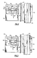
- FIG. 2 An example safety device 50 is shown in Figure 2 .
- This example includes a mounting plate 52 that is adapted to be secured in a fixed position relative to the guide rails 26.
- clips 54 secure the mounting plate 52 to the guide rail 26.
- the mounting plate 52 may be secured to another stationary structural member or a wall within the hoistway.
- the safety device 50 includes a triggering member 56 that selectively interacts with the safety brakes 42 to prevent movement of the elevator car assembly 24 beyond a selected range.
- An actuator 58 causes movement of the triggering member 56 between a retracted position shown in Figure 2 and a stopping position schematically shown in Figure 3 .
- the example actuator 58 includes a magnetic core member 60 and a conductive coil 62.
- the illustrated example operates effectively like a solenoid device. Current in the coil 62 causes a magnetic field that pulls the magnetic core member 60 in a direction to move toward the stopping position.
- a biasing member 64 biases the magnetic core 60 and the triggering member 56 into the retracted position shown in Figure 2 .
- a switch 66 operates responsive to a control 68 ( Figure 1 ) to energize the coil 62 to cause movement of the triggering member 56 toward the stopping position shown in Figure 3 .
- the force of the biasing member 64 which in this example is a coiled spring, pulls the triggering member 56 back into the retracted position shown in Figure 2 .
- control 68 operates the switch 66 and energizes the coil 62 whenever the elevator system is in an inspection mode. This may occur when a technician operates a switch in a known manner to place the elevator system into inspection mode.
- control 68 is responsive to sensors that indicate whenever a hoistway access door is open. Such an arrangement facilitates using the example safety device 50 in situations where a mechanic does not properly place the elevator system into inspection mode, for example. Such an arrangement also provides for operation of the safety device 50 when an unauthorized individual has accessed or attempted to access the hoistway space.
- the triggering member 56 is maintained in the retracted position so that the elevator car 24 is free to move along the entire range of the hoistway according to the elevator system design.
- the triggering member 56 preferably is moved into the stopping position shown schematically in Figure 3 . In this position, the triggering member 56 triggers the safety brakes 42 to stop movement of the elevator car assembly 24 beyond a height, which is dictated by the location of the safety device 50 and the corresponding interaction with the safety brakes 42. Accordingly, the safety device 50 selectively prevents the elevator car from moving beyond a selected position along the guide rails 26.
- safety devices 50 Strategically placing safety devices 50 within an elevator hoistway allows for maintaining adequate clearance between the car assembly 24 and a bottom 28 of a hoistway (i.e., an elevator pit). Similarly, safety devices 50 provide for maintaining a desired clearance between an elevator car 24 and a top 29 of a hoistway.
- the triggering member 56 is biased into the stopping position by the biasing member 64.
- the biasing member 64 urges the triggering member in the opposite direction compared to the previously described example.
- Energizing the actuator 58 moves the triggering member 56 into the retracted position.
- Switches strategically placed in the hoistway employ the triggering member as needed based on car position and operating mode.
- the mechanical bias ensures that the device will provide a stopping function even if there were a power failure or a problem with the actuator 58, for example. Otherwise, the device works like the illustrated example.
- Figures 4 and 5 schematically show the safety device 50 at a point of beginning to engage the safety brakes 42.
- One safety device 50 and one safety brake 42 are shown in Figures 4 and 5 for discussion purposes.
- the triggering member 56 causes the safety brake 42 to move into a braking position.
- a contact portion 72 on the linkage 70 makes physical contact with the triggering member 56 in the stopping position.
- Continued movement of the elevator car (in an upward direction according to Figure 4 ) causes movement of the linkage 70 and, therefore, causes a braking member 74 to engage the guide rail 26 to stop further movement of the car.
- the contact portion 72 comprises an angle that is secured to a conventional lever of a safety brake.
- the linkage 70 is specifically designed and fabricated to include the contact portion 72.
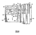
- Figure 6 shows another feature of the example embodiment.
- This example recognizes that the linkage 70 of the safety brake 42 will engage the triggering member 56 when the car is at a first position and that some additional car movement may be required before the safety brake 42 completely engages the guide rail 26 to stop further movement of the car.
- the triggering member 56 is supported on a swing plate 80 that pivots about a pivot access 82 relative to the mounting plate 52. Such pivotal movement allows for the triggering member 56 to move with the linkage 70 and the contact portion 72 during engagement of the braking member 74 against the guide rail 26.
- the triggering member 56 moves relative to the base plate 52 in a first direction between the retracted and stopping positions and moves in a second, different direction about the pivot axis 82.
- the actuator 58 is also supported on the swing plate 80 and moves with the triggering member 56 as the swing plate 80 pivots about the pivot access 82.
- the illustrated example also includes a control member 84, which is schematically illustrated as a spring.
- the control member 84 biases the swing plate 80 into a position against a stop 86 that is rigidly supported on the mounting plate 52.
- the control member 84 allows for some controlled movement of the triggering member 56 in the manner shown by comparing Figure 4 and Figure 6 , for example.
- control member 84 has a holding force that holds the swing plate 80 against the stop 86 until the linkage actuation force of the safety brake 42 exceeds the holding force of the control member 84.
- linkage actuation force increases (i.e., the braking member 74 further engages the guide rail 26) the swing plate 80, the triggering member 56 and the actuator 58 pivot about the axis 82 and the triggering member 56 moves with the contact portion 72.
- the example swing plate 80 also includes a support member 90 that includes an opening through which the triggering member 56 protrudes when placed in the stopping position.
- the support member 90 provides additional strength to the arrangement and further insulates the actuator 58 from stress associated with the impact between the triggering member 56 and the contact portion 72 of the linkage 70.
- the illustrated example provides the advantage of having an electrically powered and selectively actuated safety device that provides or ensures adequate clearance near an end of a hoistway during an inspection procedure, for example.
- By strategically placing such safety devices at appropriate heights to interact with a safety brake to activate the safety brake and prevent further movement of the car beyond a selected position provides an economical and fully automated way of ensuring adequate clearance between an elevator car and other structures within a hoistway.
- the illustrated example has the significant advantage of normally not interfering with elevator system operation.
Landscapes
- Maintenance And Inspection Apparatuses For Elevators (AREA)
- Cage And Drive Apparatuses For Elevators (AREA)
Applications Claiming Priority (1)
| Application Number | Priority Date | Filing Date | Title |
|---|---|---|---|
| PCT/US2004/040690 WO2006062503A1 (en) | 2004-12-03 | 2004-12-03 | Safety device for use in an elevator system |
Publications (3)
| Publication Number | Publication Date |
|---|---|
| EP1817251A1 EP1817251A1 (en) | 2007-08-15 |
| EP1817251A4 EP1817251A4 (en) | 2012-01-18 |
| EP1817251B1 true EP1817251B1 (en) | 2015-03-04 |
Family
ID=36578204
Family Applications (1)
| Application Number | Title | Priority Date | Filing Date |
|---|---|---|---|
| EP04813071.0A Not-in-force EP1817251B1 (en) | 2004-12-03 | 2004-12-03 | Safety device for use in an elevator system |
Country Status (7)
| Country | Link |
|---|---|
| US (1) | US7650969B2 (ja) |
| EP (1) | EP1817251B1 (ja) |
| JP (1) | JP4680262B2 (ja) |
| CN (1) | CN101072723B (ja) |
| ES (1) | ES2537756T3 (ja) |
| HK (1) | HK1115111A1 (ja) |
| WO (1) | WO2006062503A1 (ja) |
Cited By (1)
| Publication number | Priority date | Publication date | Assignee | Title |
|---|---|---|---|---|
| US10947087B2 (en) | 2016-12-14 | 2021-03-16 | Otis Elevator Company | Elevator safety system and method of operating an elevator system |
Families Citing this family (35)
| Publication number | Priority date | Publication date | Assignee | Title |
|---|---|---|---|---|
| ES2523199T3 (es) * | 2006-06-26 | 2014-11-21 | Otis Elevator Company | Tope retráctil para mantener un espacio libre superior encima de una cabina de ascensor |
| ES2353054T3 (es) * | 2006-06-30 | 2011-02-25 | Otis Elevator Company | Ascensor con un foso de poca profundidad y/o con poco espacio libre superior. |
| US8136637B2 (en) | 2006-06-30 | 2012-03-20 | Otis Elevator Company | Safety device for securing minimum spaces at the top or bottom of an elevator shaft being inspected, and elevator having such safety devices |
| WO2008057116A1 (en) * | 2006-11-08 | 2008-05-15 | Otis Elevator Company | Elevator braking device |
| US8177034B2 (en) * | 2006-11-20 | 2012-05-15 | Mitsubishi Electric Corporation | Elevator system which controls a value of overspeed |
| EP2108000B1 (de) * | 2007-01-05 | 2019-03-27 | Continental Teves AG & Co. OHG | Aufzugsanlage mit einer aufzugskabine mit einer im bereiche der aufzugskabine angeordneten bremseinrichtung zum halten und bremsen der aufzugkabine und ein verfahren zum halten und bremsen einer solchen aufzugskabine |
| CN101622185B (zh) * | 2007-01-05 | 2014-07-16 | 因温特奥股份公司 | 电梯轿厢以及用于保持和制动电梯轿厢的方法 |
| WO2010107408A1 (en) * | 2009-03-16 | 2010-09-23 | Otis Elevator Company | Electromagnetic safety trigger |
| FI120788B (fi) * | 2008-06-30 | 2010-03-15 | Kone Corp | Hissijärjestely |
| FI121423B (fi) * | 2009-04-23 | 2010-11-15 | Kone Corp | Hissin turvajärjestely |
| US9505588B2 (en) * | 2010-04-12 | 2016-11-29 | Otis Elevator Company | Retractable stop for low overhead elevators |
| EP2688825B1 (en) * | 2011-03-22 | 2024-06-26 | Otis Elevator Company | Elevator braking system |
| US9321611B2 (en) | 2011-04-19 | 2016-04-26 | Otis Elevator Company | Elevator brake having a brake release feature |
| CN102275791A (zh) * | 2011-06-03 | 2011-12-14 | 苏州富士电梯有限公司 | 电梯安全制动装置 |
| ES2547452T3 (es) * | 2011-09-30 | 2015-10-06 | Inventio Ag | Dispositivo de freno con dispositivo de accionamiento electromecánico |
| BR112013018122B1 (pt) | 2011-09-30 | 2021-03-09 | Inventio Ag | dispositivo de freio para elevador para frenagem de uma cabine de elevador, instalação de elevador e método para a frenagem de uma cabine de elevador |
| WO2014049387A1 (en) * | 2012-09-25 | 2014-04-03 | Otis Elevator Company | Compensatory measure for low overhead or low pit elevator |
| US10266373B2 (en) | 2014-10-14 | 2019-04-23 | Hangzhou Huning Elevator Parts Co., Ltd. | Automatic resetting steel wire rope brake |
| US10766739B2 (en) | 2015-01-21 | 2020-09-08 | Otis Elevator Company | Assembly for actuating an elevator car brake |
| US10654686B2 (en) * | 2015-06-30 | 2020-05-19 | Otis Elevator Company | Electromagnetic safety trigger |
| US11066274B2 (en) | 2015-06-30 | 2021-07-20 | Otis Elevator Company | Electromagnetic safety trigger |
| CN107848750B (zh) * | 2015-08-04 | 2020-04-07 | 奥的斯电梯公司 | 用于致动电梯安全制动器的装置和方法 |
| US20170073190A1 (en) * | 2015-09-14 | 2017-03-16 | Otis Elevator Company | Actuator assembly for an elevator governor system and method |
| CN106586756A (zh) * | 2015-10-14 | 2017-04-26 | 界首市迅立达电梯有限公司 | 电梯极限安全装置 |
| US10407275B2 (en) * | 2016-06-10 | 2019-09-10 | Otis Elevator Company | Detection and control system for elevator operations |
| EP3336039A1 (en) * | 2016-12-15 | 2018-06-20 | Otis Elevator Company | Acces prevention systems for locks of elevator systems |
| US10562739B2 (en) * | 2017-08-25 | 2020-02-18 | Otis Elevator Company | Synchronized electronic safety actuator |
| CN109969898B (zh) | 2017-12-28 | 2021-12-24 | 奥的斯电梯公司 | 远程触发装置,限速器组件以及电梯 |
| US10336551B1 (en) | 2018-03-23 | 2019-07-02 | Honda Motor Co., Ltd. | Over-travel limiting system and method of use thereof |
| CN111479766A (zh) * | 2018-04-10 | 2020-07-31 | 三菱电机大楼技术服务株式会社 | 使轿厢作为脚手架发挥功能的电梯控制装置 |
| EP3587323A1 (en) * | 2018-06-22 | 2020-01-01 | Otis Elevator Company | Elevator system |
| EP3617115A1 (en) * | 2018-08-31 | 2020-03-04 | KONE Corporation | An elevator system |
| US11242222B2 (en) * | 2018-10-26 | 2022-02-08 | Otis Elevator Company | Elevator braking device mechanism |
| US11104545B2 (en) * | 2018-12-10 | 2021-08-31 | Otis Elevator Company | Elevator safety actuator systems |
| EP3760561B1 (en) * | 2019-07-05 | 2022-05-11 | Otis Elevator Company | Elevator assembly with counterweight blocking stop |
Family Cites Families (32)
| Publication number | Priority date | Publication date | Assignee | Title |
|---|---|---|---|---|
| US503486A (en) * | 1893-08-15 | Elevator safety attachment | ||
| US1069070A (en) * | 1913-07-29 | Otis Elevator Co | Controlling apparatus for brakes. | |
| US1182240A (en) * | 1909-11-13 | 1916-05-09 | Otis Elevator Co | Safety device for elevators. |
| US1223819A (en) * | 1912-03-13 | 1917-04-24 | Guy K Mitchell | Controlling means for elevators. |
| GB197790A (en) | 1922-03-15 | 1923-05-24 | Lyons & Co Ltd J | Improvements in or relating to systems of control for lifts |
| GB252122A (en) | 1925-05-13 | 1926-09-09 | Waygood Otis Ltd | Improvements in or relating to electric elevator systems |
| US2765874A (en) * | 1953-10-07 | 1956-10-09 | Staley Elevator Company Inc | Bi-powered elevator brakes |
| US3211258A (en) * | 1960-10-05 | 1965-10-12 | Dickmann Giulio | Intermittently actuated switch selector for an elevator control |
| US3674113A (en) * | 1970-03-13 | 1972-07-04 | Sidney Richmon | Automatic elevator stopping apparatus |
| JPS5228189B2 (ja) | 1973-07-26 | 1977-07-25 | ||
| US4832158A (en) * | 1987-01-20 | 1989-05-23 | Delaware Capital Formation, Inc. | Elevator system having microprocessor-based door operator |
| US4923055A (en) * | 1989-01-24 | 1990-05-08 | Delaware Capital Formation, Inc. | Safety mechanism for preventing unintended motion in traction elevators |
| CN2068496U (zh) * | 1990-05-30 | 1991-01-02 | 上海春江电器仪表厂 | 井架升降防冲顶限位装置 |
| US5002158A (en) * | 1990-08-03 | 1991-03-26 | Otis Elevator Company | Elevator safety |
| US5321216A (en) * | 1991-04-09 | 1994-06-14 | Otis Elevator Company | Restraining elevator car motion while the doors are open |
| JPH04333481A (ja) * | 1991-05-02 | 1992-11-20 | Hitachi Building Syst Eng & Service Co Ltd | エレベータの安全装置 |
| JPH08133631A (ja) | 1994-11-02 | 1996-05-28 | Mitsubishi Denki Bill Techno Service Kk | 油圧エレベーターの休止装置 |
| US5806633A (en) * | 1995-12-22 | 1998-09-15 | Macuga; Henry J. | Elevator safety system incorporating false pit |
| US5773771A (en) * | 1996-07-30 | 1998-06-30 | Chatham; Charles | Apparatus for preventing unintended movement of elevator car |
| JP4107728B2 (ja) | 1998-09-07 | 2008-06-25 | 東芝エレベータ株式会社 | エレベータ装置 |
| US6173813B1 (en) * | 1998-12-23 | 2001-01-16 | Otis Elevator Company | Electronic control for an elevator braking system |
| US6202797B1 (en) * | 1999-08-26 | 2001-03-20 | Otis Elevator Company | Automatic protection of elevator mechanics |
| US6223861B1 (en) * | 1999-08-30 | 2001-05-01 | Otis Elevator Company | Elevator hoistway access safety |
| ATE299835T1 (de) * | 1999-12-20 | 2005-08-15 | Mitsubishi Elevator Europ B V | Schachtsicherheitssystem für aufzug |
| DE50015424D1 (de) * | 2000-01-19 | 2008-12-11 | Thyssenkrupp Aufzugswerke Gmbh | Aufzuganlage mit verringerter Schachtgrubentiefe |
| WO2003008317A1 (fr) * | 2001-06-29 | 2003-01-30 | Mitsubishi Denki Kabushiki Kaisha | Dispositif de freinage de secours pour ascenseur |
| ITMI20022457A1 (it) | 2002-11-19 | 2004-05-20 | Centoducati S P A | Apparecchiatura meccanica di sicurezza per fosse ridotte di ascensori |
| PE20040794A1 (es) * | 2003-03-05 | 2004-12-22 | Inventio Ag | Prevencion de acceso no autorizado a cajas de ascensor |
| JP4673574B2 (ja) * | 2003-05-07 | 2011-04-20 | インベンテイオ・アクテイエンゲゼルシヤフト | 一時的保護スペースを供給するための装置を用いたエレベータ設備、該装置の実装方法、および一時的保護スペースを供給するための方法 |
| JP2005255294A (ja) * | 2004-03-10 | 2005-09-22 | Mitsubishi Electric Building Techno Service Co Ltd | エレベータの安全装置 |
| JP4664370B2 (ja) | 2004-09-29 | 2011-04-06 | オーチス エレベータ カンパニー | エレベータかごの安全停止装置 |
| US8136637B2 (en) * | 2006-06-30 | 2012-03-20 | Otis Elevator Company | Safety device for securing minimum spaces at the top or bottom of an elevator shaft being inspected, and elevator having such safety devices |
-
2004
- 2004-12-03 WO PCT/US2004/040690 patent/WO2006062503A1/en active Application Filing
- 2004-12-03 EP EP04813071.0A patent/EP1817251B1/en not_active Not-in-force
- 2004-12-03 US US11/576,273 patent/US7650969B2/en not_active Expired - Fee Related
- 2004-12-03 ES ES04813071.0T patent/ES2537756T3/es active Active
- 2004-12-03 JP JP2007529808A patent/JP4680262B2/ja not_active Expired - Fee Related
- 2004-12-03 CN CN2004800445353A patent/CN101072723B/zh not_active Expired - Fee Related
-
2008
- 2008-05-08 HK HK08105195.4A patent/HK1115111A1/xx not_active IP Right Cessation
Cited By (1)
| Publication number | Priority date | Publication date | Assignee | Title |
|---|---|---|---|---|
| US10947087B2 (en) | 2016-12-14 | 2021-03-16 | Otis Elevator Company | Elevator safety system and method of operating an elevator system |
Also Published As
| Publication number | Publication date |
|---|---|
| EP1817251A4 (en) | 2012-01-18 |
| JP2008511521A (ja) | 2008-04-17 |
| CN101072723B (zh) | 2010-11-10 |
| JP4680262B2 (ja) | 2011-05-11 |
| CN101072723A (zh) | 2007-11-14 |
| ES2537756T3 (es) | 2015-06-11 |
| EP1817251A1 (en) | 2007-08-15 |
| US7650969B2 (en) | 2010-01-26 |
| WO2006062503A1 (en) | 2006-06-15 |
| HK1115111A1 (en) | 2008-11-21 |
| US20070289820A1 (en) | 2007-12-20 |
Similar Documents
| Publication | Publication Date | Title |
|---|---|---|
| EP1817251B1 (en) | Safety device for use in an elevator system | |
| EP2035313B1 (en) | Safety device for securing minimum spaces at the top or bottom of an elevator shaft being inspected, and elevator having such safety devices | |
| EP1739046B1 (en) | Emergency stop system of elevator | |
| US8028808B2 (en) | Retractable stop for maintaining overhead clearance above an elevator car | |
| US5321216A (en) | Restraining elevator car motion while the doors are open | |
| US9809420B2 (en) | Compensatory measure for low overhead or low pit elevator | |
| WO2005102898A1 (ja) | エレベータ制御装置 | |
| US7729806B2 (en) | Elevator controller | |
| US5183978A (en) | Elevator governor rope block actuation in low speed emergency situations | |
| US7556127B2 (en) | Elevator control device | |
| KR100889440B1 (ko) | 엘리베이터 시스템용 안전 장치 | |
| US20240286869A1 (en) | Elevator arrangement and method of operating elevator | |
| WO2023047561A1 (ja) | エレベータ装置 | |
| KR100429303B1 (ko) | 엘리베이터의 안전장치 | |
| JP6498806B1 (ja) | 油圧エレベータの安全装置 | |
| KR200219245Y1 (ko) | 엘리베이터의 안전장치 | |
| CN117585551A (zh) | 电梯坑维护系统 | |
| JP2019142666A (ja) | 油圧エレベータの安全装置 | |
| KR20060063809A (ko) | 엘리베이터 장치 |
Legal Events
| Date | Code | Title | Description |
|---|---|---|---|
| PUAI | Public reference made under article 153(3) epc to a published international application that has entered the european phase |
Free format text: ORIGINAL CODE: 0009012 |
|
| 17P | Request for examination filed |
Effective date: 20070525 |
|
| AK | Designated contracting states |
Kind code of ref document: A1 Designated state(s): AT BE BG CH CY CZ DE DK EE ES FI FR GB GR HU IE IS IT LI LT LU MC NL PL PT RO SE SI SK TR |
|
| DAX | Request for extension of the european patent (deleted) | ||
| A4 | Supplementary search report drawn up and despatched |
Effective date: 20111221 |
|
| RIC1 | Information provided on ipc code assigned before grant |
Ipc: B66B 5/00 20060101ALI20111215BHEP Ipc: B66B 5/02 20060101AFI20111215BHEP |
|
| 17Q | First examination report despatched |
Effective date: 20130927 |
|
| GRAP | Despatch of communication of intention to grant a patent |
Free format text: ORIGINAL CODE: EPIDOSNIGR1 |
|
| INTG | Intention to grant announced |
Effective date: 20141029 |
|
| GRAS | Grant fee paid |
Free format text: ORIGINAL CODE: EPIDOSNIGR3 |
|
| GRAA | (expected) grant |
Free format text: ORIGINAL CODE: 0009210 |
|
| AK | Designated contracting states |
Kind code of ref document: B1 Designated state(s): AT BE BG CH CY CZ DE DK EE ES FI FR GB GR HU IE IS IT LI LT LU MC NL PL PT RO SE SI SK TR |
|
| REG | Reference to a national code |
Ref country code: GB Ref legal event code: FG4D |
|
| REG | Reference to a national code |
Ref country code: CH Ref legal event code: EP |
|
| REG | Reference to a national code |
Ref country code: IE Ref legal event code: FG4D |
|
| REG | Reference to a national code |
Ref country code: AT Ref legal event code: REF Ref document number: 713673 Country of ref document: AT Kind code of ref document: T Effective date: 20150415 |
|
| REG | Reference to a national code |
Ref country code: DE Ref legal event code: R096 Ref document number: 602004046749 Country of ref document: DE Effective date: 20150416 |
|
| REG | Reference to a national code |
Ref country code: ES Ref legal event code: FG2A Ref document number: 2537756 Country of ref document: ES Kind code of ref document: T3 Effective date: 20150611 |
|
| REG | Reference to a national code |
Ref country code: AT Ref legal event code: MK05 Ref document number: 713673 Country of ref document: AT Kind code of ref document: T Effective date: 20150304 Ref country code: NL Ref legal event code: VDEP Effective date: 20150304 |
|
| PG25 | Lapsed in a contracting state [announced via postgrant information from national office to epo] |
Ref country code: FI Free format text: LAPSE BECAUSE OF FAILURE TO SUBMIT A TRANSLATION OF THE DESCRIPTION OR TO PAY THE FEE WITHIN THE PRESCRIBED TIME-LIMIT Effective date: 20150304 Ref country code: SE Free format text: LAPSE BECAUSE OF FAILURE TO SUBMIT A TRANSLATION OF THE DESCRIPTION OR TO PAY THE FEE WITHIN THE PRESCRIBED TIME-LIMIT Effective date: 20150304 Ref country code: LT Free format text: LAPSE BECAUSE OF FAILURE TO SUBMIT A TRANSLATION OF THE DESCRIPTION OR TO PAY THE FEE WITHIN THE PRESCRIBED TIME-LIMIT Effective date: 20150304 |
|
| REG | Reference to a national code |
Ref country code: LT Ref legal event code: MG4D |
|
| PG25 | Lapsed in a contracting state [announced via postgrant information from national office to epo] |
Ref country code: AT Free format text: LAPSE BECAUSE OF FAILURE TO SUBMIT A TRANSLATION OF THE DESCRIPTION OR TO PAY THE FEE WITHIN THE PRESCRIBED TIME-LIMIT Effective date: 20150304 Ref country code: GR Free format text: LAPSE BECAUSE OF FAILURE TO SUBMIT A TRANSLATION OF THE DESCRIPTION OR TO PAY THE FEE WITHIN THE PRESCRIBED TIME-LIMIT Effective date: 20150605 |
|
| PG25 | Lapsed in a contracting state [announced via postgrant information from national office to epo] |
Ref country code: NL Free format text: LAPSE BECAUSE OF FAILURE TO SUBMIT A TRANSLATION OF THE DESCRIPTION OR TO PAY THE FEE WITHIN THE PRESCRIBED TIME-LIMIT Effective date: 20150304 |
|
| PG25 | Lapsed in a contracting state [announced via postgrant information from national office to epo] |
Ref country code: SK Free format text: LAPSE BECAUSE OF FAILURE TO SUBMIT A TRANSLATION OF THE DESCRIPTION OR TO PAY THE FEE WITHIN THE PRESCRIBED TIME-LIMIT Effective date: 20150304 Ref country code: CZ Free format text: LAPSE BECAUSE OF FAILURE TO SUBMIT A TRANSLATION OF THE DESCRIPTION OR TO PAY THE FEE WITHIN THE PRESCRIBED TIME-LIMIT Effective date: 20150304 Ref country code: PT Free format text: LAPSE BECAUSE OF FAILURE TO SUBMIT A TRANSLATION OF THE DESCRIPTION OR TO PAY THE FEE WITHIN THE PRESCRIBED TIME-LIMIT Effective date: 20150706 Ref country code: EE Free format text: LAPSE BECAUSE OF FAILURE TO SUBMIT A TRANSLATION OF THE DESCRIPTION OR TO PAY THE FEE WITHIN THE PRESCRIBED TIME-LIMIT Effective date: 20150304 Ref country code: RO Free format text: LAPSE BECAUSE OF FAILURE TO SUBMIT A TRANSLATION OF THE DESCRIPTION OR TO PAY THE FEE WITHIN THE PRESCRIBED TIME-LIMIT Effective date: 20150304 |
|
| REG | Reference to a national code |
Ref country code: FR Ref legal event code: PLFP Year of fee payment: 12 |
|
| PG25 | Lapsed in a contracting state [announced via postgrant information from national office to epo] |
Ref country code: IS Free format text: LAPSE BECAUSE OF FAILURE TO SUBMIT A TRANSLATION OF THE DESCRIPTION OR TO PAY THE FEE WITHIN THE PRESCRIBED TIME-LIMIT Effective date: 20150704 Ref country code: PL Free format text: LAPSE BECAUSE OF FAILURE TO SUBMIT A TRANSLATION OF THE DESCRIPTION OR TO PAY THE FEE WITHIN THE PRESCRIBED TIME-LIMIT Effective date: 20150304 |
|
| REG | Reference to a national code |
Ref country code: DE Ref legal event code: R097 Ref document number: 602004046749 Country of ref document: DE |
|
| PG25 | Lapsed in a contracting state [announced via postgrant information from national office to epo] |
Ref country code: IT Free format text: LAPSE BECAUSE OF FAILURE TO SUBMIT A TRANSLATION OF THE DESCRIPTION OR TO PAY THE FEE WITHIN THE PRESCRIBED TIME-LIMIT Effective date: 20150304 |
|
| PLBE | No opposition filed within time limit |
Free format text: ORIGINAL CODE: 0009261 |
|
| STAA | Information on the status of an ep patent application or granted ep patent |
Free format text: STATUS: NO OPPOSITION FILED WITHIN TIME LIMIT |
|
| PG25 | Lapsed in a contracting state [announced via postgrant information from national office to epo] |
Ref country code: DK Free format text: LAPSE BECAUSE OF FAILURE TO SUBMIT A TRANSLATION OF THE DESCRIPTION OR TO PAY THE FEE WITHIN THE PRESCRIBED TIME-LIMIT Effective date: 20150304 |
|
| 26N | No opposition filed |
Effective date: 20151207 |
|
| PG25 | Lapsed in a contracting state [announced via postgrant information from national office to epo] |
Ref country code: SI Free format text: LAPSE BECAUSE OF FAILURE TO SUBMIT A TRANSLATION OF THE DESCRIPTION OR TO PAY THE FEE WITHIN THE PRESCRIBED TIME-LIMIT Effective date: 20150304 |
|
| PGFP | Annual fee paid to national office [announced via postgrant information from national office to epo] |
Ref country code: ES Payment date: 20151202 Year of fee payment: 12 |
|
| PG25 | Lapsed in a contracting state [announced via postgrant information from national office to epo] |
Ref country code: BE Free format text: LAPSE BECAUSE OF NON-PAYMENT OF DUE FEES Effective date: 20151231 |
|
| PG25 | Lapsed in a contracting state [announced via postgrant information from national office to epo] |
Ref country code: LU Free format text: LAPSE BECAUSE OF FAILURE TO SUBMIT A TRANSLATION OF THE DESCRIPTION OR TO PAY THE FEE WITHIN THE PRESCRIBED TIME-LIMIT Effective date: 20151203 Ref country code: MC Free format text: LAPSE BECAUSE OF FAILURE TO SUBMIT A TRANSLATION OF THE DESCRIPTION OR TO PAY THE FEE WITHIN THE PRESCRIBED TIME-LIMIT Effective date: 20150304 |
|
| REG | Reference to a national code |
Ref country code: CH Ref legal event code: PL |
|
| GBPC | Gb: european patent ceased through non-payment of renewal fee |
Effective date: 20151203 |
|
| PG25 | Lapsed in a contracting state [announced via postgrant information from national office to epo] |
Ref country code: BE Free format text: LAPSE BECAUSE OF FAILURE TO SUBMIT A TRANSLATION OF THE DESCRIPTION OR TO PAY THE FEE WITHIN THE PRESCRIBED TIME-LIMIT Effective date: 20150304 |
|
| REG | Reference to a national code |
Ref country code: IE Ref legal event code: MM4A |
|
| PG25 | Lapsed in a contracting state [announced via postgrant information from national office to epo] |
Ref country code: IE Free format text: LAPSE BECAUSE OF NON-PAYMENT OF DUE FEES Effective date: 20151203 Ref country code: CH Free format text: LAPSE BECAUSE OF NON-PAYMENT OF DUE FEES Effective date: 20151231 Ref country code: GB Free format text: LAPSE BECAUSE OF NON-PAYMENT OF DUE FEES Effective date: 20151203 Ref country code: LI Free format text: LAPSE BECAUSE OF NON-PAYMENT OF DUE FEES Effective date: 20151231 |
|
| REG | Reference to a national code |
Ref country code: FR Ref legal event code: PLFP Year of fee payment: 13 |
|
| PG25 | Lapsed in a contracting state [announced via postgrant information from national office to epo] |
Ref country code: BG Free format text: LAPSE BECAUSE OF FAILURE TO SUBMIT A TRANSLATION OF THE DESCRIPTION OR TO PAY THE FEE WITHIN THE PRESCRIBED TIME-LIMIT Effective date: 20150304 Ref country code: HU Free format text: LAPSE BECAUSE OF FAILURE TO SUBMIT A TRANSLATION OF THE DESCRIPTION OR TO PAY THE FEE WITHIN THE PRESCRIBED TIME-LIMIT; INVALID AB INITIO Effective date: 20041203 |
|
| PG25 | Lapsed in a contracting state [announced via postgrant information from national office to epo] |
Ref country code: CY Free format text: LAPSE BECAUSE OF FAILURE TO SUBMIT A TRANSLATION OF THE DESCRIPTION OR TO PAY THE FEE WITHIN THE PRESCRIBED TIME-LIMIT Effective date: 20150304 |
|
| REG | Reference to a national code |
Ref country code: DE Ref legal event code: R082 Ref document number: 602004046749 Country of ref document: DE Representative=s name: SCHMITT-NILSON SCHRAUD WAIBEL WOHLFROM PATENTA, DE |
|
| PG25 | Lapsed in a contracting state [announced via postgrant information from national office to epo] |
Ref country code: TR Free format text: LAPSE BECAUSE OF FAILURE TO SUBMIT A TRANSLATION OF THE DESCRIPTION OR TO PAY THE FEE WITHIN THE PRESCRIBED TIME-LIMIT Effective date: 20150304 |
|
| REG | Reference to a national code |
Ref country code: FR Ref legal event code: PLFP Year of fee payment: 14 |
|
| PGFP | Annual fee paid to national office [announced via postgrant information from national office to epo] |
Ref country code: DE Payment date: 20171120 Year of fee payment: 14 Ref country code: FR Payment date: 20171121 Year of fee payment: 14 |
|
| PG25 | Lapsed in a contracting state [announced via postgrant information from national office to epo] |
Ref country code: ES Free format text: LAPSE BECAUSE OF NON-PAYMENT OF DUE FEES Effective date: 20161204 |
|
| REG | Reference to a national code |
Ref country code: ES Ref legal event code: FD2A Effective date: 20181119 |
|
| REG | Reference to a national code |
Ref country code: DE Ref legal event code: R119 Ref document number: 602004046749 Country of ref document: DE |
|
| PG25 | Lapsed in a contracting state [announced via postgrant information from national office to epo] |
Ref country code: DE Free format text: LAPSE BECAUSE OF NON-PAYMENT OF DUE FEES Effective date: 20190702 Ref country code: FR Free format text: LAPSE BECAUSE OF NON-PAYMENT OF DUE FEES Effective date: 20181231 |