EP1816697B1 - Brennstoffreformierungsvorrichtung und Herstellungsverfahren - Google Patents
Brennstoffreformierungsvorrichtung und Herstellungsverfahren Download PDFInfo
- Publication number
- EP1816697B1 EP1816697B1 EP07101636.4A EP07101636A EP1816697B1 EP 1816697 B1 EP1816697 B1 EP 1816697B1 EP 07101636 A EP07101636 A EP 07101636A EP 1816697 B1 EP1816697 B1 EP 1816697B1
- Authority
- EP
- European Patent Office
- Prior art keywords
- channel
- substrate
- reforming apparatus
- support layer
- reaction
- Prior art date
- Legal status (The legal status is an assumption and is not a legal conclusion. Google has not performed a legal analysis and makes no representation as to the accuracy of the status listed.)
- Expired - Fee Related
Links
Images


Classifications
-
- C—CHEMISTRY; METALLURGY
- C01—INORGANIC CHEMISTRY
- C01B—NON-METALLIC ELEMENTS; COMPOUNDS THEREOF; METALLOIDS OR COMPOUNDS THEREOF NOT COVERED BY SUBCLASS C01C
- C01B3/00—Hydrogen; Gaseous mixtures containing hydrogen; Separation of hydrogen from mixtures containing it; Purification of hydrogen; Reversible storage of hydrogen
- C01B3/02—Production of hydrogen; Production of gaseous mixtures containing hydrogen
- C01B3/32—Production of hydrogen; Production of gaseous mixtures containing hydrogen by reaction of gaseous or liquid organic compounds with gasifying agents, e.g. water, carbon dioxide or air
- C01B3/34—Production of hydrogen; Production of gaseous mixtures containing hydrogen by reaction of gaseous or liquid organic compounds with gasifying agents, e.g. water, carbon dioxide or air by reaction of hydrocarbons with gasifying agents
- C01B3/38—Production of hydrogen; Production of gaseous mixtures containing hydrogen by reaction of gaseous or liquid organic compounds with gasifying agents, e.g. water, carbon dioxide or air by reaction of hydrocarbons with gasifying agents using catalysts
- C01B3/384—Production of hydrogen; Production of gaseous mixtures containing hydrogen by reaction of gaseous or liquid organic compounds with gasifying agents, e.g. water, carbon dioxide or air by reaction of hydrocarbons with gasifying agents using catalysts with external heating of the catalyst
-
- C—CHEMISTRY; METALLURGY
- C01—INORGANIC CHEMISTRY
- C01B—NON-METALLIC ELEMENTS; COMPOUNDS THEREOF; METALLOIDS OR COMPOUNDS THEREOF NOT COVERED BY SUBCLASS C01C
- C01B3/00—Hydrogen; Gaseous mixtures containing hydrogen; Separation of hydrogen from mixtures containing it; Purification of hydrogen; Reversible storage of hydrogen
- C01B3/02—Production of hydrogen; Production of gaseous mixtures containing hydrogen
- C01B3/32—Production of hydrogen; Production of gaseous mixtures containing hydrogen by reaction of gaseous or liquid organic compounds with gasifying agents, e.g. water, carbon dioxide or air
- C01B3/34—Production of hydrogen; Production of gaseous mixtures containing hydrogen by reaction of gaseous or liquid organic compounds with gasifying agents, e.g. water, carbon dioxide or air by reaction of hydrocarbons with gasifying agents
- C01B3/38—Production of hydrogen; Production of gaseous mixtures containing hydrogen by reaction of gaseous or liquid organic compounds with gasifying agents, e.g. water, carbon dioxide or air by reaction of hydrocarbons with gasifying agents using catalysts
-
- B—PERFORMING OPERATIONS; TRANSPORTING
- B01—PHYSICAL OR CHEMICAL PROCESSES OR APPARATUS IN GENERAL
- B01J—CHEMICAL OR PHYSICAL PROCESSES, e.g. CATALYSIS OR COLLOID CHEMISTRY; THEIR RELEVANT APPARATUS
- B01J19/00—Chemical, physical or physico-chemical processes in general; Their relevant apparatus
- B01J19/0093—Microreactors, e.g. miniaturised or microfabricated reactors
-
- B—PERFORMING OPERATIONS; TRANSPORTING
- B01—PHYSICAL OR CHEMICAL PROCESSES OR APPARATUS IN GENERAL
- B01J—CHEMICAL OR PHYSICAL PROCESSES, e.g. CATALYSIS OR COLLOID CHEMISTRY; THEIR RELEVANT APPARATUS
- B01J19/00—Chemical, physical or physico-chemical processes in general; Their relevant apparatus
- B01J19/24—Stationary reactors without moving elements inside
- B01J19/248—Reactors comprising multiple separated flow channels
- B01J19/249—Plate-type reactors
-
- C—CHEMISTRY; METALLURGY
- C01—INORGANIC CHEMISTRY
- C01B—NON-METALLIC ELEMENTS; COMPOUNDS THEREOF; METALLOIDS OR COMPOUNDS THEREOF NOT COVERED BY SUBCLASS C01C
- C01B3/00—Hydrogen; Gaseous mixtures containing hydrogen; Separation of hydrogen from mixtures containing it; Purification of hydrogen; Reversible storage of hydrogen
- C01B3/02—Production of hydrogen; Production of gaseous mixtures containing hydrogen
- C01B3/22—Production of hydrogen; Production of gaseous mixtures containing hydrogen by decomposition of gaseous or liquid organic compounds
- C01B3/24—Production of hydrogen; Production of gaseous mixtures containing hydrogen by decomposition of gaseous or liquid organic compounds of hydrocarbons
- C01B3/26—Production of hydrogen; Production of gaseous mixtures containing hydrogen by decomposition of gaseous or liquid organic compounds of hydrocarbons using catalysts
-
- H—ELECTRICITY
- H01—ELECTRIC ELEMENTS
- H01M—PROCESSES OR MEANS, e.g. BATTERIES, FOR THE DIRECT CONVERSION OF CHEMICAL ENERGY INTO ELECTRICAL ENERGY
- H01M8/00—Fuel cells; Manufacture thereof
- H01M8/06—Combination of fuel cells with means for production of reactants or for treatment of residues
- H01M8/0606—Combination of fuel cells with means for production of reactants or for treatment of residues with means for production of gaseous reactants
- H01M8/0612—Combination of fuel cells with means for production of reactants or for treatment of residues with means for production of gaseous reactants from carbon-containing material
- H01M8/0618—Reforming processes, e.g. autothermal, partial oxidation or steam reforming
-
- H—ELECTRICITY
- H01—ELECTRIC ELEMENTS
- H01M—PROCESSES OR MEANS, e.g. BATTERIES, FOR THE DIRECT CONVERSION OF CHEMICAL ENERGY INTO ELECTRICAL ENERGY
- H01M8/00—Fuel cells; Manufacture thereof
- H01M8/06—Combination of fuel cells with means for production of reactants or for treatment of residues
- H01M8/0606—Combination of fuel cells with means for production of reactants or for treatment of residues with means for production of gaseous reactants
- H01M8/0612—Combination of fuel cells with means for production of reactants or for treatment of residues with means for production of gaseous reactants from carbon-containing material
- H01M8/0625—Combination of fuel cells with means for production of reactants or for treatment of residues with means for production of gaseous reactants from carbon-containing material in a modular combined reactor/fuel cell structure
-
- B—PERFORMING OPERATIONS; TRANSPORTING
- B01—PHYSICAL OR CHEMICAL PROCESSES OR APPARATUS IN GENERAL
- B01J—CHEMICAL OR PHYSICAL PROCESSES, e.g. CATALYSIS OR COLLOID CHEMISTRY; THEIR RELEVANT APPARATUS
- B01J2219/00—Chemical, physical or physico-chemical processes in general; Their relevant apparatus
- B01J2219/00781—Aspects relating to microreactors
- B01J2219/00783—Laminate assemblies, i.e. the reactor comprising a stack of plates
-
- B—PERFORMING OPERATIONS; TRANSPORTING
- B01—PHYSICAL OR CHEMICAL PROCESSES OR APPARATUS IN GENERAL
- B01J—CHEMICAL OR PHYSICAL PROCESSES, e.g. CATALYSIS OR COLLOID CHEMISTRY; THEIR RELEVANT APPARATUS
- B01J2219/00—Chemical, physical or physico-chemical processes in general; Their relevant apparatus
- B01J2219/00781—Aspects relating to microreactors
- B01J2219/00819—Materials of construction
- B01J2219/00835—Comprising catalytically active material
-
- B—PERFORMING OPERATIONS; TRANSPORTING
- B01—PHYSICAL OR CHEMICAL PROCESSES OR APPARATUS IN GENERAL
- B01J—CHEMICAL OR PHYSICAL PROCESSES, e.g. CATALYSIS OR COLLOID CHEMISTRY; THEIR RELEVANT APPARATUS
- B01J2219/00—Chemical, physical or physico-chemical processes in general; Their relevant apparatus
- B01J2219/00781—Aspects relating to microreactors
- B01J2219/00873—Heat exchange
-
- B—PERFORMING OPERATIONS; TRANSPORTING
- B01—PHYSICAL OR CHEMICAL PROCESSES OR APPARATUS IN GENERAL
- B01J—CHEMICAL OR PHYSICAL PROCESSES, e.g. CATALYSIS OR COLLOID CHEMISTRY; THEIR RELEVANT APPARATUS
- B01J2219/00—Chemical, physical or physico-chemical processes in general; Their relevant apparatus
- B01J2219/24—Stationary reactors without moving elements inside
- B01J2219/2401—Reactors comprising multiple separate flow channels
- B01J2219/245—Plate-type reactors
- B01J2219/2451—Geometry of the reactor
- B01J2219/2453—Plates arranged in parallel
-
- B—PERFORMING OPERATIONS; TRANSPORTING
- B01—PHYSICAL OR CHEMICAL PROCESSES OR APPARATUS IN GENERAL
- B01J—CHEMICAL OR PHYSICAL PROCESSES, e.g. CATALYSIS OR COLLOID CHEMISTRY; THEIR RELEVANT APPARATUS
- B01J2219/00—Chemical, physical or physico-chemical processes in general; Their relevant apparatus
- B01J2219/24—Stationary reactors without moving elements inside
- B01J2219/2401—Reactors comprising multiple separate flow channels
- B01J2219/245—Plate-type reactors
- B01J2219/2451—Geometry of the reactor
- B01J2219/2456—Geometry of the plates
- B01J2219/2458—Flat plates, i.e. plates which are not corrugated or otherwise structured, e.g. plates with cylindrical shape
-
- B—PERFORMING OPERATIONS; TRANSPORTING
- B01—PHYSICAL OR CHEMICAL PROCESSES OR APPARATUS IN GENERAL
- B01J—CHEMICAL OR PHYSICAL PROCESSES, e.g. CATALYSIS OR COLLOID CHEMISTRY; THEIR RELEVANT APPARATUS
- B01J2219/00—Chemical, physical or physico-chemical processes in general; Their relevant apparatus
- B01J2219/24—Stationary reactors without moving elements inside
- B01J2219/2401—Reactors comprising multiple separate flow channels
- B01J2219/245—Plate-type reactors
- B01J2219/2451—Geometry of the reactor
- B01J2219/2456—Geometry of the plates
- B01J2219/2459—Corrugated plates
-
- B—PERFORMING OPERATIONS; TRANSPORTING
- B01—PHYSICAL OR CHEMICAL PROCESSES OR APPARATUS IN GENERAL
- B01J—CHEMICAL OR PHYSICAL PROCESSES, e.g. CATALYSIS OR COLLOID CHEMISTRY; THEIR RELEVANT APPARATUS
- B01J2219/00—Chemical, physical or physico-chemical processes in general; Their relevant apparatus
- B01J2219/24—Stationary reactors without moving elements inside
- B01J2219/2401—Reactors comprising multiple separate flow channels
- B01J2219/245—Plate-type reactors
- B01J2219/2461—Heat exchange aspects
- B01J2219/2465—Two reactions in indirect heat exchange with each other
-
- B—PERFORMING OPERATIONS; TRANSPORTING
- B01—PHYSICAL OR CHEMICAL PROCESSES OR APPARATUS IN GENERAL
- B01J—CHEMICAL OR PHYSICAL PROCESSES, e.g. CATALYSIS OR COLLOID CHEMISTRY; THEIR RELEVANT APPARATUS
- B01J2219/00—Chemical, physical or physico-chemical processes in general; Their relevant apparatus
- B01J2219/24—Stationary reactors without moving elements inside
- B01J2219/2401—Reactors comprising multiple separate flow channels
- B01J2219/245—Plate-type reactors
- B01J2219/2476—Construction materials
- B01J2219/2477—Construction materials of the catalysts
- B01J2219/2479—Catalysts coated on the surface of plates or inserts
-
- B—PERFORMING OPERATIONS; TRANSPORTING
- B01—PHYSICAL OR CHEMICAL PROCESSES OR APPARATUS IN GENERAL
- B01J—CHEMICAL OR PHYSICAL PROCESSES, e.g. CATALYSIS OR COLLOID CHEMISTRY; THEIR RELEVANT APPARATUS
- B01J2219/00—Chemical, physical or physico-chemical processes in general; Their relevant apparatus
- B01J2219/24—Stationary reactors without moving elements inside
- B01J2219/2401—Reactors comprising multiple separate flow channels
- B01J2219/245—Plate-type reactors
- B01J2219/2476—Construction materials
- B01J2219/2483—Construction materials of the plates
- B01J2219/2485—Metals or alloys
- B01J2219/2486—Steel
-
- C—CHEMISTRY; METALLURGY
- C01—INORGANIC CHEMISTRY
- C01B—NON-METALLIC ELEMENTS; COMPOUNDS THEREOF; METALLOIDS OR COMPOUNDS THEREOF NOT COVERED BY SUBCLASS C01C
- C01B2203/00—Integrated processes for the production of hydrogen or synthesis gas
- C01B2203/02—Processes for making hydrogen or synthesis gas
- C01B2203/0205—Processes for making hydrogen or synthesis gas containing a reforming step
- C01B2203/0227—Processes for making hydrogen or synthesis gas containing a reforming step containing a catalytic reforming step
-
- C—CHEMISTRY; METALLURGY
- C01—INORGANIC CHEMISTRY
- C01B—NON-METALLIC ELEMENTS; COMPOUNDS THEREOF; METALLOIDS OR COMPOUNDS THEREOF NOT COVERED BY SUBCLASS C01C
- C01B2203/00—Integrated processes for the production of hydrogen or synthesis gas
- C01B2203/06—Integration with other chemical processes
- C01B2203/066—Integration with other chemical processes with fuel cells
-
- C—CHEMISTRY; METALLURGY
- C01—INORGANIC CHEMISTRY
- C01B—NON-METALLIC ELEMENTS; COMPOUNDS THEREOF; METALLOIDS OR COMPOUNDS THEREOF NOT COVERED BY SUBCLASS C01C
- C01B2203/00—Integrated processes for the production of hydrogen or synthesis gas
- C01B2203/08—Methods of heating or cooling
- C01B2203/0805—Methods of heating the process for making hydrogen or synthesis gas
- C01B2203/0811—Methods of heating the process for making hydrogen or synthesis gas by combustion of fuel
-
- C—CHEMISTRY; METALLURGY
- C01—INORGANIC CHEMISTRY
- C01B—NON-METALLIC ELEMENTS; COMPOUNDS THEREOF; METALLOIDS OR COMPOUNDS THEREOF NOT COVERED BY SUBCLASS C01C
- C01B2203/00—Integrated processes for the production of hydrogen or synthesis gas
- C01B2203/10—Catalysts for performing the hydrogen forming reactions
- C01B2203/1041—Composition of the catalyst
- C01B2203/1047—Group VIII metal catalysts
- C01B2203/1052—Nickel or cobalt catalysts
- C01B2203/1058—Nickel catalysts
-
- Y—GENERAL TAGGING OF NEW TECHNOLOGICAL DEVELOPMENTS; GENERAL TAGGING OF CROSS-SECTIONAL TECHNOLOGIES SPANNING OVER SEVERAL SECTIONS OF THE IPC; TECHNICAL SUBJECTS COVERED BY FORMER USPC CROSS-REFERENCE ART COLLECTIONS [XRACs] AND DIGESTS
- Y02—TECHNOLOGIES OR APPLICATIONS FOR MITIGATION OR ADAPTATION AGAINST CLIMATE CHANGE
- Y02E—REDUCTION OF GREENHOUSE GAS [GHG] EMISSIONS, RELATED TO ENERGY GENERATION, TRANSMISSION OR DISTRIBUTION
- Y02E60/00—Enabling technologies; Technologies with a potential or indirect contribution to GHG emissions mitigation
- Y02E60/30—Hydrogen technology
- Y02E60/50—Fuel cells
-
- Y—GENERAL TAGGING OF NEW TECHNOLOGICAL DEVELOPMENTS; GENERAL TAGGING OF CROSS-SECTIONAL TECHNOLOGIES SPANNING OVER SEVERAL SECTIONS OF THE IPC; TECHNICAL SUBJECTS COVERED BY FORMER USPC CROSS-REFERENCE ART COLLECTIONS [XRACs] AND DIGESTS
- Y02—TECHNOLOGIES OR APPLICATIONS FOR MITIGATION OR ADAPTATION AGAINST CLIMATE CHANGE
- Y02P—CLIMATE CHANGE MITIGATION TECHNOLOGIES IN THE PRODUCTION OR PROCESSING OF GOODS
- Y02P70/00—Climate change mitigation technologies in the production process for final industrial or consumer products
- Y02P70/50—Manufacturing or production processes characterised by the final manufactured product
Definitions
- the present invention relates to a fuel reforming apparatus, and more particularly, to a fuel reforming apparatus and a manufacturing method of the fuel reforming apparatus in which thermal energy is generated through an oxidation reaction of a fuel and a reformed gas containing hydrogen is generated through a reforming reaction of the fuel by using the thermal energy.
- a fuel cell is an electricity generating system for generating electrical energy by using a hydrocarbon fuel.
- Fuel cells can be classified into a polymer electrolyte membrane fuel cell and a direct oxidation membrane fuel cell, which is generally referred to as a direct methanol fuel cell (DMFC) in the art.
- DMFC direct methanol fuel cell
- the polymer electrolyte membrane fuel cell has an excellent output characteristic, a low operation temperature, and fast starting and response characteristics in comparison to other types of fuel cells.
- the polymer electrolyte membrane fuel cell has an advantage that the fuel cell can be used in a wide range of applications such as a mobile power source for vehicles, a distributed power source for home or buildings, and a small size power source for electronic apparatuses.
- the fuel cell system employing the polymer electrolyte membrane fuel cell includes a fuel cell main body that can be referred to as a stack, a fuel reforming apparatus which reforms a fuel to generate a reformed gas containing hydrogen and supplies the reformed gas to the stack, and an oxidant gas supply unit which supplies oxidant gas to the stack.
- the stack generates electricity through an electro-chemical reaction of the reformed gas, which is supplied from the fuel reforming apparatus, and the oxidant gas, which is supplied from the oxidant gas supply unit.
- the fuel reforming apparatus includes a thermal source unit which generates thermal energy through an oxidation reaction induced by an oxidation catalyst, and a reforming reaction unit which generates a reformed gas containing hydrogen by the use of the thermal energy and through a reforming reaction of the fuel.
- a plurality of substrates made of stainless steel (SUS) are laminated so as to form a thermal source unit and a reforming reaction unit.
- the substrates are provided with a channel through which a fuel flows, a catalyst support layer which is formed on a surface of the channel, and a catalyst layer which is formed on the catalyst support layer to promote an oxidation reaction of the thermal source unit and a reforming reaction of the reforming reaction unit.
- the catalyst support layer supports a catalyst layer, and is made of aluminum oxide (Al 2 O 3 ) that can be formed over the surface of the channel.
- thermal energy is generated through an oxidation reaction of a gaseous fuel such as butane that can be easily obtained in the market.
- a reformed gas is generated through a reforming reaction of the gaseous fuel and by the use of the thermal energy.
- a reforming reaction of the gaseous fuel occurs in the reforming reaction unit at a temperature in a range of 600 °C to 800 °C.
- the thermal energy that is necessary to maintain the temperature is provided by a thermal source unit, which generates the thermal energy through an oxidation reaction of the gaseous fuel.
- the thermal source unit then supplies the thermal energy to the reforming reaction unit.
- a plurality of substrates having channels are laminated, and the laminated substrates bond at a high temperature (in a range of 500 °C to 900 °C).
- the fuel reforming apparatus has a problem.
- the catalyst support layer formed on the channels of the substrates is peeled off along with the catalyst layer or changes its phase during the bonding process at high temperature.
- durability of the catalyst support layer deteriorates with time, which causes a shorter lifespan of the fuel reforming apparatus and degradation in the reliability of the fuel reforming apparatus.
- the fuel reforming apparatus is manufactured by separately coating the channels with catalyst support layer material such as aluminum oxide (Al 2 O 3 ), which makes the manufacturing process of the fuel reforming apparatus more complicated. Accordingly, productivity of manufacturing the fuel reforming apparatus deteriorates.
- catalyst support layer material such as aluminum oxide (Al 2 O 3 )
- the present invention provides a fuel reforming apparatus that can solve the problems described above.
- the reforming apparatus of the present invention is made by directly oxidizing the channel formed on the substrate. Therefore, the reforming apparatus of the present invention causes no damage during high temperature bonding process or high temperature operation of the fuel reforming apparatus. Reliability of the fuel reforming apparatus of the present invention is accordingly improved.
- the catalyst support layer of the fuel reforming apparatus of the present invention is formed by oxidizing the channels of the substrates. Therefore, additional coating process for catalyst support layer is not necessary, which improves the productivity of manufacturing the fuel reforming apparatus.
- a fuel reforming apparatus according to claim 1 and a method of manufacturing a fuel reforming apparatus according to claim 10.
- a fuel reforming apparatus including a reaction substrate made of a metal, a channel formed on an upper surface of the reaction substrate, a support layer formed on the channel where the support layer includes an oxidized layer of the metal and is made by oxidizing the channel, a catalyst layer formed on the support layer, and a cover contacting the upper surface of the reaction substrate.
- the metal can be stainless steel, nickel steel, or chromium steel.
- the reaction substrate and the cover can be assembled together by a joining member.
- the fuel reforming apparatus can further include a path formed in the channel, and the path is sealed by the cover.
- a reactant can be supplied into the path.
- the reactant can include butane.
- the reaction substrate can be a thermal source unit to generate thermal energy or a reforming unit to generate a reformed gas.
- a fuel reforming apparatus including a first reaction substrate made of a first metal, a first channel formed on an upper surface of the first reaction substrate, a first catalyst support layer formed on the first channel where the first catalyst support layer includes an oxidized layer of the first metal, a first catalyst layer formed on the first catalyst support layer, a second reaction substrate made of a second metal and contacting the upper surface of the first reaction substrate, a second channel formed on an upper surface of the second reaction substrate, a second catalyst support layer formed on the second channel where the second catalyst support layer includes an oxidized layer of the second metal, a second catalyst layer formed on the second catalyst support layer, and a cover plate contacting the upper surface of the second reaction substrate.
- Each of the first metal and the second metal can be stainless steel, nickel steel, or chromium steel.
- the first reaction substrate, the second reaction substrate, and the cover plate can be assembled together by a joining member.
- the fuel reforming apparatus can further include a first path formed in the first channel.
- the first path is sealed by the second reaction substrate, and a first reactant is supplied into the first path.
- the first reaction substrate can be a thermal source unit to generate thermal energy through an oxidation reaction of the first reactant contained in the first path.
- the fuel reforming apparatus can further include a second path formed in the second channel.
- the second path is sealed by the cover plate, and a second reactant is supplied into the second path.
- the second reaction substrate can be a reforming unit to generate a reformed gas through a reforming reaction of the second reactant contained in the second path.
- the reformed gas can include hydrogen gas.
- Each of the first reactant and the second reactant can include butane.
- a manufacturing method of a fuel reforming apparatus including steps of preparing a first substrate made of a first metal, forming a first channel on an upper surface of the first substrate, oxidizing an inner surface of the first channel where the oxidized inner surface of the first channel is a first catalyst support layer, forming a first catalyst layer on the oxidized inner surface of the first channel, preparing a second substrate made of a second metal, forming a second channel on an upper surface of the second substrate, oxidizing an inner surface of the second channel where the oxidized inner surface of the second channel is a second catalyst support layer, forming a second catalyst layer on the oxidized inner surface of the second channel, placing the second substrate on the upper surface of the first substrate in a manner that a lower surface of the second substrate contacts the upper surface of the first substrate, and placing a cover plate on the upper surface of the second substrate.
- the first substrate and the second substrate can be made of stainless steel, nickel steel or chromium steel.
- the step of oxidizing an inner surface of the first channel includes steps of supplying oxygen gas into the first channel, and heating the first channel in temperature range between 500 °C and 700 °C.
- a manufacturing method of a fuel reforming apparatus including steps of preparing a first substrate made of a first metal, forming a first channel on an upper surface of the first substrate, preparing a second substrate made of a second metal, forming a second channel on an upper surface of the second substrate, placing the second substrate on the upper surface of the first substrate in a manner that a lower surface of the second substrate contacts the upper surface of the first substrate, placing a cover plate on the upper surface of the second substrate, oxidizing inner surfaces of the first channel and the second channel after both of the step of placing the second substrate and the step of placing a cover plate where the oxidized inner surfaces of the first channel and the second channel are a catalyst support layer, and forming a catalyst layer on the oxidized inner surfaces of the first channel and the second channel.
- the first substrate and the second substrate can be made of stainless steel, nickel steel or chromium steel.
- the step of oxidizing inner surfaces of the first channel and the second channel includes steps of supplying oxygen gas into the first channel and the second channel, and heating the first channel and the second channel in temperature range between 500 °C and 700 °C.
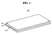
- FIG. 1 is a perspective view of a fuel reforming apparatus constructed as a first embodiment of the present invention.
- fuel reforming apparatus 100 generates a reformed gas through a reforming reaction of a fuel.
- the reformed gas contains hydrogen gas. Because the reforming reaction of the fuel requires thermal energy, fuel reforming apparatus 100 also generates heat through an oxidation reaction of the fuel. The heat is supplied to activate the reforming reaction of the fuel.
- the fuel can be a hydrocarbon fuel in the form of liquid or gas.
- the hydrocarbon fuel is a fuel that contains hydrogen, which can include methanol, ethanol, LPG, LNG, and gasoline.
- the fuel can be a gaseous fuel containing butane as a principal component.
- Fuel reforming apparatus 100 is employed in a fuel cell system so as to produce a reformed gas and to supply the reformed gas to a stack of the fuel cell system.
- the fuel cell system generates electricity through an oxidation reaction of the reformed gas and a reduction reaction of an oxidant gas.
- the oxidant gas used for the fuel cell system can be oxygen stored in a separate storage, or can be oxygen contained in atmospheric air.
- Fuel reforming apparatus 100 includes thermal source unit 10 which generates thermal energy through an oxidation reaction between a gaseous fuel and air (hereinafter, referred to as "first reactant"), and reforming reaction unit 30 which generates a reformed gas through a stream reforming (SR) reaction between a gaseous fuel and water (hereinafter, referred to as “second reactant”) and by the thermal energy produced by thermal source unit 10.
- first reactant oxidation reaction between a gaseous fuel and air
- second reactant stream reforming
- Fuel reforming apparatus 100 is a laminate type reforming apparatus in which thermal source unit 10 and reforming reaction unit 30 are laminated together.
- Thermal source unit 10 generates thermal energy in a range of a predetermined temperature through an oxidation reaction of the first reactant. Then, thermal source unit 10 supplies the thermal energy to reforming reaction unit 30.
- the thermal energy generated by thermal source unit 10 has a temperature in a range of 600 °C to 800 °C, which is the required temperature for the reforming reaction of the second reactant.
- First path 11d along which first reactant flows, is formed in thermal source unit 10. First path 11d will be explained in detail later referring to FIGS. 2 and 3 .
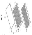
- FIG. 2 is an exploded perspective view of the fuel reforming apparatus shown in FIG. 1 .
- FIG. 3 is a vertical cross-sectional view of the fuel reforming apparatus shown in FIG. 1 .
- thermal source unit 10 includes plate-type first reaction substrate 11.
- First channel 11c is formed on an upper surface of first reaction substrate 11.
- First reactant can flow through first channel 11c.
- Reforming reaction unit 30 includes plate-type second reaction substrate 31.
- Second channel 31c is formed on an upper surface of second reaction substrate 31.
- Second reactant can flow through second channel 31c.
- Reforming reaction unit 30 is laminated with thermal source unit 10 in a manner that a lower surface of second reaction substrate 31 closely contacts the upper surface of first reaction substrate 11.
- Fuel reforming apparatus 100 includes cover 40 which includes the second reaction substrate 31 and a cover plate 50.
- Cover plate 50 is laminated with second reaction substrate 31 in a manner that cover plate 50 closely contacts the upper surface of second reaction substrate 31.
- First path 11d is formed in first channel 11c of first reaction substrate 11, and is the path along which the first reactant flows. Because second reaction substrate 31 closely contacts the upper surface of first reaction substrate 11, the lower surface of second reaction substrate 31 covers first channel 11c and seals first path 11d. Therefore, first reactant can flow along first path 11d without a leak. Second path 31d is formed in second channel 31c of second reaction substrate 31. Because cover plate 50 closely contacts the upper surface of second reaction substrate 31, cover plate 50 covers second channel 31c and seals second path 31d. Therefore, second reactant can flow along second path 31d without a leak.
- First reaction substrate 11 has a shape of a square plate made of stainless steel (SUS). Multiple first channels 11c can be formed on the upper surface of the first reaction substrate 11 as shown in FIG. 2 . In this case, first channels 11c are formed between ribs, which protrude from the upper surface of the first reaction substrate 11 and are aligned parallel to each other in a certain interval. First channel 11c has a shape of a groove which runs from one edge to the other edge of first reaction substrate 11.
- SUS stainless steel
- First catalyst support layer 11f is formed in an inner surface of first channel 11c, and oxidation catalyst layer (first catalyst layer) 11e is formed on a surface of first catalyst support layer 11f to promote an oxidation reaction of the first reactant.
- First catalyst support layer 11f supports oxidation catalyst layer 11e, and is also referred to herein as a catalyst containing layer.
- First catalyst support layer 11f is constructed by oxidizing the inner surface of first channel 11c. After the process of oxidization, an oxidized steel film, which is first catalyst support layer 11f, is formed on the inner surface of first channel 11c.
- First catalyst support layer 11f can be formed with an oxidized steel such as Fe 2 O 3 , Fe 3 O 4 , or FeO.
- Second reaction substrate 31 has a shape of a square plate made of stainless steel (SUS).
- the lower surface of second reaction substrate 31 closely contacts the upper surface of first reaction substrate 11.
- Second channel 31c is constructed between ribs which protrude from the upper surface of second reaction substrate 31. As shown in FIG. 2 , in this embodiment, second channel 31c is continuously formed from one end to another end, and is not broken in pieces. Each end of second channel 31c is connected to each of holes 31m, which are placed at corners of second reaction substrate 31.
- Second catalyst support layer 31f is formed in an inner surface of second channel 31c, and reforming catalyst layer (second catalyst layer) 31e is formed on a surface of second catalyst support layer 31f to promote a reforming reaction of the second reactant.
- Second catalyst support layer 31f supports reforming catalyst layer 31e, and is also referred to herein as a catalyst containing layer.
- Second catalyst support layer 31f is constructed by oxidizing the inner surface of the second channel 31c. After the process of oxidization, an oxidized steel film, which works as second catalyst support layer 31f, is formed on the inner surface of second channel 31c. Second catalyst support layer 31f can be made of oxidized steel such as Fe 2 O 3 , Fe 3 O 4 , or FeO.
- fuel reforming apparatus 100 includes first reaction substrate 11, second reaction substrate 31, and cover plate 50. These components are laminated to be closely interconnected with each other.
- first reaction substrate 11 and second reaction substrate 31 can be sequentially laminated to be closely bonded with each other, and cover plate 50 can be closely bonded with the upper surface of second reaction substrate 31.
- First reaction substrate 11, second reaction substrate 31, and cover plate 50 can be closely interconnected with each other by means of a joining member such as a bolt and a nut.
- the joining member means a physical connection device.
- first reaction substrate 11, second reaction substrate 31, and cover plate 50 can be closely bonded with each other by means of a bonding member such as welding or brazing.
- the bonding member can be any connection member requiring physical or chemical reaction.
- FIG. 4 is a flowchart illustrating a manufacturing method of a fuel reforming apparatus constructed as the first embodiment of the present invention.
- the manufacturing method of the fuel reforming apparatus according to the first embodiment of the present invention includes steps of preparing substrates made of stainless steel (step S10), forming a channel by etching an upper surface of each substrate (step S20), forming a catalyst support layer by oxidizing the inner surface of the channel (step S30), forming a catalyst layer on the catalyst support layer (step S40), and laminating the substrates with each other and assembling a cover plate on the upper surface of the uppermost substrate (step S50).
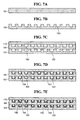
- FIGS. 5A to 5E are cross-sectional views for explaining a manufacturing method of the fuel reforming apparatus constructed as the first embodiment of the present invention.
- substrate 61 made of stainless steel is prepared.
- FIG. 5B which is step S20 of FIG. 4 , substrate 61 is subjected to an anisotropic etching or isotropic etching process, and channel 63 is formed on the upper surface of substrates 61.
- Channel 63 has a predetermined width and depth.
- ribs which protrude from the upper surface of substrates 61, are formed. The ribs are aligned in a certain interval. Channel 63 is formed in spaces between the ribs.
- an inner surface of channel 63 of substrate 61 is oxidized through a thermal oxidation method at temperature in a range of 500 °C to 900 °C. Oxygen or oxidation solution can be used for the oxidation process.
- catalyst support layer 64 is formed on the inner surface of channel 63.
- Catalyst support layer 64 is oxidized steel layer, and can be formed of a material such as Fe 2 O 3 , Fe 3 O 4 , or FeO.
- catalyst layer 65 is formed on catalyst support layer 64 by a slurry method.
- Catalyst layer 65 can include additional layers or additives that promote reactions in thermal source unit and the reforming reaction unit.
- FIG. 5E which is step S50 of FIG. 4 , another identical substrate 61 is manufactured through the aforementioned processes, and two substrates 61 are laminated together.
- Cover plate 70 is laminated on the upper surface of uppermost substrate 61.
- Uppermost substrates 61 and cover plate 70 are interconnected to each other. In this stage, manufacturing process of fuel reforming apparatus 100 of the first embodiment of the present invention is completed.
- An additional catalyst support layer such as an aluminum oxide (Al 2 O 3 ) layer can be formed on the inner surface of channel 63 of substrate 61 made of stainless steel.
- This aluminum oxide film could cause problems such as a damage of film during high temperature bonding process of substrates 61 and cover plate 70 or high temperature operation of fuel reforming apparatus.
- the inner surface of channel 63 is directly oxidized so as to form catalyst support layer 64 formed with an oxidized steel film.
- Catalyst layer 65 is formed on catalyst support layer 64. Accordingly, catalyst support layer 64 is no longer damaged or peeled off along with catalyst layer 65, or its phase does not change even under the high temperature condition, which is in a range of 600 °C to 800 °C, during the operation of the fuel reforming apparatus.
- FIG. 6 is a flowchart illustrating a manufacturing method of a fuel reforming apparatus constructed as a second embodiment of the present invention.
- the manufacturing method of the fuel reforming apparatus according to the second embodiment of the present invention includes steps of preparing substrates made of stainless steel (step S110), forming a channel by etching the upper surface of each substrate (step S120), bonding the substrates with each other and bonding a cover plate with the upper surface of the uppermost substrate (step S130), forming a catalyst support layer by oxidizing the inner surface of the channel (step S140), and forming a catalyst layer on the catalyst support layer (step S150).
- FIGS. 7A to 7E are cross-sectional views for explaining a manufacturing method of the fuel reforming apparatus constructed as the second embodiment of the present invention.
- substrate 161 made of stainless steel is prepared.
- Channel 163 is formed on the upper surfaces of substrates 161.
- FIG. 7C another identical substrate 161 is manufactured through the process shown in FIGS. 7A and 7B .
- Two substrates 161 are laminated together, and cover plate 170 is laminated on the upper surface of uppermost substrate 161.
- Uppermost substrate 161 and cover plate 170 are interconnected.
- the inner surface of channel 163 is oxidized through a thermal oxidation method, in which oxygen or oxidation solution are supplied into channel 163 of each substrate 161 at temperature in a range of about 500 °C to 900 °C.
- an oxidized steel film which is catalyst support layer 164, is formed on the inner surface of channel 163 of each substrate 161.
- the oxidized steel film formed through a rapid reaction with oxygen at high temperature has excellent corrosion resistance and rigidity. Thus, the oxidized steel film is not easily peeled off from the inner surface of channel 163.
- catalyst layer 165 is formed on catalyst support layer 164 by supplying a catalyst material into channel 163 of each substrate 161 by a slurry method or the like. Accordingly, the manufacturing process of the fuel reforming apparatus of the second embodiment of the present invention is completed through the aforementioned series of processes.
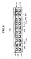
- FIG. 8 is a cross-sectional view of a fuel reforming apparatus constructed as a third embodiment of the present invention.
- fuel reforming apparatus 200 is constructed by sequentially laminating thermal source unit 210 which generates thermal energy through an oxidation reaction between a gaseous fuel and air, reforming reaction unit 230 which generates a reformed gas by using the thermal energy, and cover plate 250.
- Thermal source unit 210 includes plate-type first reaction substrate 211 having first channel 211c, through which fuel and air flow.
- Reforming reaction unit 230 includes plate-type second reaction substrate 231 having second channel 231c. Reforming reaction unit 230 is closely bonded with the upper surface of first reaction substrate 211, and a gaseous fuel and water flows through second channel 231c.
- first path 211d is formed in first channel 211c, and is covered by second reaction substrate 231.
- Second path 231d is formed in second channel 231c, and covered by cover plate 250.
- first reaction substrate 211 and second reaction substrate 231 have a shape of a square plate made of nickel steel.
- Nickel is a principal component of nickel steel.
- Nickel steel in the present invention has a broad meaning including nickel alloy steel.
- Oxidation catalyst layer 211e is formed on an inner surface of first channel 211c so as to promote an oxidation reaction.
- First catalyst support layer 211f is formed between the inner surface of first channel 211c and oxidation catalyst layer 211e so as to support oxidation catalyst layer 211e.
- First catalyst support layer 211f is formed by oxidizing first reaction substrate 211 made of nickel alloy steel. An oxidized steel film made during the oxidization process forms first catalyst support layer 211f.
- Reforming catalyst layer 231e is constructed with the inner surface of second channel 231c formed on second reaction substrate 231.
- Second catalyst support layer 231 f is formed between the inner surface of second channel 231c and reforming catalyst layer 231e so as to support reforming catalyst layer 231e.
- Second catalyst support layer 231f is constructed with an oxide layer which is formed by oxidizing second reaction substrate 231.
- Nickel alloy steel can be oxidized by using a thermal oxidization method used in the first embodiment.
- First catalyst support layer 211f and second catalyst support layer 231f are constructed with an oxidized steel film containing a principal component such as Fe 2 O 3 , Fe 3 O 4 , and FeO.
- the reaction substrates are made of nickel alloy steel having excellent thermal resistance, thereby increasing the lifespan of each reaction substrate. Furthermore, since the catalyst support layer is formed on the surface of the channel by oxidizing nickel steel at high temperature, the catalyst support layer can be prevented from being peeled off or from changing its phase even at high temperature.
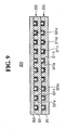
- FIG. 9 is a cross-sectional view of a fuel reforming apparatus constructed as a fourth embodiment of the present invention.
- fuel reforming apparatus 300 is constructed by sequentially laminating thermal source unit 310 which generates thermal energy through an oxidation reaction between a gaseous fuel and air, reforming reaction unit 330 which generates a reformed gas by using the thermal energy, and cover plate 350.
- Thermal source unit 310 includes plate-type first reaction substrate 311 having first channel 311c through which fuel and air flow.
- Reforming reaction unit 330 includes plate-type second reaction substrate 331 having second channel 331c. Reforming reaction unit 330 is closely bonded with the upper surface of first reaction substrate 311, and a gaseous fuel and water flow through second channel 331 c.
- first path 311d is formed in first channel 311c, and sealed by second reaction substrate 331. Further, second path 331d is formed in second channel 331c, and sealed by cover plate 350.
- first reaction substrate 311 and second reaction substrate 331 have a shape of a square plate made of chromium steel. Chromium is a principal component of chromium steel, and chromium steel in the present invention has a broad meaning that includes chromium alloy steel.
- Oxidation catalyst layer 311e is formed on the inner surface of first channel 311c so as to promote an oxidation reaction.
- First catalyst support layer 311f is formed between the inner surface of first channel 311c and oxidation catalyst layer 311e so as to support oxidation catalyst layer 311e.
- First catalyst support layer 311f is constructed with an oxide layer which is formed by oxidizing first reaction substrate 311 made of chromium alloy steel.
- Reforming catalyst layer 331e is constructed in the inner surface of second channel 331c formed on second reaction substrate 331.
- Second catalyst support layer 331f is formed between the inner surface of second channel 331c and reforming catalyst layer 331e so as to support reforming catalyst layer 331e.
- Second catalyst support layer 331f is constructed with an oxide layer which is formed by oxidizing second reaction substrate 331.
- Chromium alloy steel can be oxidized by using a thermal oxidization method used in the first embodiment.
- First catalyst support layer 311f and second catalyst support layer 331f are constructed with an oxidized steel film containing a principal component such as Fe 2 O 3 , Fe 3 O 4 , and FeO.
- reaction substrates are made of chromium alloy steel having excellent corrosion resistance, thereby lengthening the lifespan of each reaction substrate. Furthermore, since a catalyst support layer is formed on a surface of a channel by oxidizing chromium steel at high temperature, the catalyst support layer can be prevented from being peeled off or from changing its phase even at the high temperature.
- a substrate made of stainless steel, nickel steel, or chromium steel is oxidized so that a catalyst support layer is formed on a surface of a channel by using oxidized steel.
- the catalyst support layer can be prevented from being peeled off or from changing its phase even at high temperature. Therefore, durability of the catalyst support layer is improved, thereby not only increasing the lifespan of the fuel reforming apparatus but also further enhancing the reliability of the fuel reforming apparatus.
- both of the first and the second reaction substrate in the embodiments, are described as being made of the same metal, each of the first and the second reaction substrate can be made of a different metal material.
- Each of the metal material also can be referred to as a first metal or a second metal.
- a catalyst support layer is formed by oxidizing a surface of a channel formed on a substrate, which is different from a method of separately forming catalyst support layer made of a different material from the substrate on a channel of a the substrate.
- an overall manufacturing process of the apparatus can be simplified. Accordingly, the productivity of the fuel reforming apparatus can be further improved.
Landscapes
- Chemical & Material Sciences (AREA)
- Chemical Kinetics & Catalysis (AREA)
- Organic Chemistry (AREA)
- Engineering & Computer Science (AREA)
- Life Sciences & Earth Sciences (AREA)
- Combustion & Propulsion (AREA)
- Inorganic Chemistry (AREA)
- General Health & Medical Sciences (AREA)
- Health & Medical Sciences (AREA)
- Manufacturing & Machinery (AREA)
- Sustainable Development (AREA)
- Sustainable Energy (AREA)
- Electrochemistry (AREA)
- General Chemical & Material Sciences (AREA)
- Hydrogen, Water And Hydrids (AREA)
- Fuel Cell (AREA)
- Catalysts (AREA)
Claims (14)
- Brennstoffreformierungsvorrichtung (100, 200, 300), aufweisend:ein Reaktionssubstrat (11, 61, 161, 211, 311), das aus rostfreiem Stahl, Nickelstahl oder Chromstahl hergestellt ist;einen Kanal (11c, 63, 163, 211c, 311c), der auf einer Oberfläche des Reaktionssubstrats ausgebildet ist;eine Katalysatorträgerschicht (11f, 64, 164, 211 f, 311f), die im Kanal zum Tragen einer Katalysatorschicht ausgebildet ist, wobei die Katalysatorträgerschicht eine Schicht aus oxidiertem Stahl aufweist, die eine oxidierte Oberfläche des Reaktionssubstrats ist.
- Brennstoffreformierungsvorrichtung nach Anspruch 1, weiterhin aufweisend:eine Katalysatorschicht (11e, 65, 165, 211e, 311e) auf der Katalysatorträgerschicht; undeine Abdeckung (40), die mit der Oberfläche des Reaktionssubstrats in Kontakt steht.
- Brennstoffreformierungsvorrichtung nach Anspruch 2, wobei die Abdeckung ein zweites Reaktionssubstrat (31, 231, 331) aufweist, das mit der Oberfläche des Reaktionssubstrats in Kontakt steht.
- Brennstoffreformierungsvorrichtung nach Anspruch 3, wobei das zweite Reaktionssubstrat aus einem Metall hergestellt ist und weiterhin aufweist:einen zweiten Kanal (31c, 231 c, 331 c), der auf einer Oberfläche des zweiten Reaktionssubstrats ausgebildet ist;eine zweite Katalysatorträgerschicht (31f, 231f, 331 f), die im zweiten Kanal ausgebildet ist, wobei die zweite Katalysatorträgerschicht eine oxidierte Oberfläche des Metalls aufweist; undeine zweite Katalysatorschicht (31e, 231e, 331 e), die auf der zweiten Katalysatorträgerschicht ausgebildet ist.
- Brennstoffreformierungsvorrichtung nach Anspruch 3 oder 4, wobei das zweite Reaktionssubstrat eine Reformierungseinheit zum Erzeugen eines reformierten Gases aufweist.
- Brennstoffreformierungsvorrichtung nach einem der Ansprüche 2 bis 5, wobei das Reaktionssubstrat und die Abdeckung durch ein Verbindungselement miteinander verbunden sind.
- Brennstoffreformierungsvorrichtung nach einem der vorhergehenden Ansprüche, aufweisend ein Mittel, das jeden des Kanals und/oder des zweiten Kanals mit einem Reaktionsmittel versorgt.
- Brennstoffreformierungsvorrichtung nach Anspruch 4, wobei das Metall rostfreien Stahl, Nickelstahl oder Chromstahl aufweist.
- Brennstoffreformierungsvorrichtung nach einem der vorhergehenden Ansprüche, wobei das Reaktionssubstrat eine Wärmequelleneinheit (10, 210, 310) zum Erzeugen von thermischer Energie aufweist.
- Verfahren zur Herstellung einer Brennstoffreformierungsvorrichtung, aufweisend die folgenden Schritte:Herstellung eines ersten Substrats, das rostfreien Stahl, Nickelstahl oder Chromstahl aufweist;Ausbildung eines ersten Kanals auf einer Oberfläche des ersten Substrats;Oxidieren einer Innenseite des ersten Kanals zur Ausbildung einer Schicht aus oxidiertem Stahl als erster Katalysatorträgerschicht.
- Verfahren nach Anspruch 10, weiterhin aufweisend:Ausbildung einer ersten Katalysatorschicht auf der ersten Katalysatorträgerschicht;Herstellung eines zweiten Substrats, das ein Metall aufweist;Ausbildung eines zweiten Kanals auf einer Oberfläche des zweiten Substrats;Oxidieren einer Innenseite des zweiten Kanals zur Ausbildung einer oxidierten Oberfläche des zweiten Substrats als zweiter Katalysatorträgerschicht;Ausbildung einer zweiten Katalysatorschicht auf der zweiten Katalysatorträgerschicht;Positionieren des zweiten Substrats auf dem ersten Substrat derart, dass eine Unterseite des zweiten Substrats mit einer Oberseite des ersten Substrats in Kontakt steht; undPositionieren einer Deckplatte auf einer Oberseite des zweiten Substrats.
- Verfahren nach Anspruch 11, wobei das Metall rostfreien Stahl, Nickelstahl oder Chromstahl aufweist.
- Verfahren nach einem der Ansprüche 10 bis 12, wobei der Schritt des Oxidierens einer Innenseite des ersten Kanals die folgenden Schritte aufweist:Zuführung von Sauerstoffgas in den ersten Kanal; undErwärmung des ersten Kanals in einem Temperaturbereich zwischen etwa 500 °C und 900 °C.
- Verfahren nach einem der Ansprüche 10 bis 13, wobei die Schritte des Oxidierens der Innenseiten des ersten Kanals und des zweiten Kanals und der Ausbildung einer Katalysatorschicht auf den oxidierten Innenseiten des ersten Kanals und des zweiten Kanals nach dem Schritt des Positionierens des zweiten Substrats und nach dem Schritt des Positionierens einer Deckplatte durchgeführt werden.
Applications Claiming Priority (1)
| Application Number | Priority Date | Filing Date | Title |
|---|---|---|---|
| KR1020060010565A KR101223627B1 (ko) | 2006-02-03 | 2006-02-03 | 연료 개질장치 및 그 제조 방법 |
Publications (3)
| Publication Number | Publication Date |
|---|---|
| EP1816697A2 EP1816697A2 (de) | 2007-08-08 |
| EP1816697A3 EP1816697A3 (de) | 2009-12-02 |
| EP1816697B1 true EP1816697B1 (de) | 2013-06-05 |
Family
ID=38069749
Family Applications (1)
| Application Number | Title | Priority Date | Filing Date |
|---|---|---|---|
| EP07101636.4A Expired - Fee Related EP1816697B1 (de) | 2006-02-03 | 2007-02-02 | Brennstoffreformierungsvorrichtung und Herstellungsverfahren |
Country Status (5)
| Country | Link |
|---|---|
| US (1) | US8273141B2 (de) |
| EP (1) | EP1816697B1 (de) |
| JP (1) | JP4855284B2 (de) |
| KR (1) | KR101223627B1 (de) |
| CN (1) | CN100546088C (de) |
Families Citing this family (6)
| Publication number | Priority date | Publication date | Assignee | Title |
|---|---|---|---|---|
| KR20060080385A (ko) * | 2005-01-05 | 2006-07-10 | 삼성에스디아이 주식회사 | 연료 전지 시스템, 개질기, 반응 기판 및 그 반응 기판의제조 방법 |
| BRPI0711443A2 (pt) * | 2006-05-08 | 2011-11-01 | Compactgtl Plc | reator catalìtico compacto, métodos de realizar combustão, e de realizar uma reação rápida no mesmo, e, de controlar o gradiente térmico em um reator catalìtico |
| JP5120167B2 (ja) * | 2008-09-12 | 2013-01-16 | カシオ計算機株式会社 | ステンレス鋼系材料の処理方法、ステンレス鋼系材料、反応器及び燃料電池装置 |
| CN106910928A (zh) * | 2015-12-18 | 2017-06-30 | 中国科学院大连化学物理研究所 | 一种高温甲醇内重整燃料电池 |
| CN109692629B (zh) * | 2017-10-20 | 2021-03-02 | 中国石化工程建设有限公司 | 重整制氢反应器及其转化炉以及重整制氢反应的方法 |
| CN109950590B (zh) * | 2019-04-02 | 2020-11-10 | 中氢新能技术有限公司 | 燃料电池甲醇重整器 |
Family Cites Families (23)
| Publication number | Priority date | Publication date | Assignee | Title |
|---|---|---|---|---|
| JP2923972B2 (ja) | 1989-05-12 | 1999-07-26 | 日産化学工業株式会社 | カラーフィルター保護コート剤 |
| JPH06111838A (ja) | 1992-09-30 | 1994-04-22 | Toshiba Corp | 改質器、改質システム、及び燃料電池システム |
| DE19511817C2 (de) | 1995-03-30 | 1997-10-09 | Aeg Energietechnik Gmbh | Wärmetauscher in Plattenbauweise mit Reformer |
| DE19653991A1 (de) * | 1996-12-21 | 1998-06-25 | Degussa | Reaktor zur Durchführung endothermer katalytischer Reaktionen |
| JP4251467B2 (ja) | 1998-04-10 | 2009-04-08 | 大日本印刷株式会社 | カラーフィルタ保護膜形成用共重合樹脂 |
| JPH11292930A (ja) | 1998-04-10 | 1999-10-26 | Dainippon Printing Co Ltd | 共重合樹脂 |
| JPH11326623A (ja) | 1998-05-12 | 1999-11-26 | Toppan Printing Co Ltd | 液晶表示装置用カラーフィルタの保護膜用樹脂組成物及びその保護膜用樹脂組成物を用いた液晶表示装置用カラーフィルタ |
| JP2000105456A (ja) | 1998-07-31 | 2000-04-11 | Dainippon Printing Co Ltd | 感光性樹脂組成物及びカラ―フィルタ― |
| KR100334426B1 (ko) | 1998-07-31 | 2002-05-03 | 기타지마 요시토시 | 감광성 수지 조성물 및 컬러 필터 |
| DE60020762T2 (de) | 1999-02-25 | 2006-05-04 | Dai Nippon Printing Co., Ltd. | Lichtempfindliche Harzzusammensetzung, Farbfilter und dafür geeignetes Copolymerharz |
| JP4222457B2 (ja) | 2000-01-14 | 2009-02-12 | 日本化薬株式会社 | カラーフィルターの保護層用の熱硬化性樹脂組成物及びその硬化物 |
| JP2002143675A (ja) | 2000-09-04 | 2002-05-21 | Kawasaki Heavy Ind Ltd | 反応器並びに該反応器に用いる触媒及びその製造方法 |
| KR100592418B1 (ko) | 2002-03-02 | 2006-06-22 | 주식회사 삼양이엠에스 | 액정표시소자 컬럼 스페이서용 레지스트 조성물 |
| EP1377370A1 (de) * | 2001-04-12 | 2004-01-07 | Mir-Chem GmbH | Vorrichtung und verfahren zum katalytischen reformieren von kohlenwasserstoffen oder alkoholen |
| DE112004000052T5 (de) * | 2003-02-06 | 2005-08-11 | Dai Nippon Printing Co., Ltd. | Mikroreaktor und Herstellungsverfahren für diesen |
| US7435274B2 (en) * | 2003-02-27 | 2008-10-14 | Kabushiki Kaisha Toshiba | Metal particle-dispersed composite oxides, metal particle-dispersed composite oxide-sintered bodies, method of manufacturing metal particle-dispersed composite oxides, and hydrocarbon-based fuel reformer |
| JP2004331434A (ja) | 2003-05-06 | 2004-11-25 | Dainippon Printing Co Ltd | 水素製造用のマイクロリアクターおよびその製造方法 |
| JP4486429B2 (ja) | 2003-07-14 | 2010-06-23 | 大日本印刷株式会社 | 水素製造用のマイクロリアクターおよびその製造方法 |
| JP2005066509A (ja) | 2003-08-26 | 2005-03-17 | Casio Comput Co Ltd | 触媒反応器の製造方法 |
| KR100536255B1 (ko) | 2004-05-13 | 2005-12-12 | 삼성에스디아이 주식회사 | 연료전지용 개질기, 그의 제조방법 및 이를 포함하는연료전지 시스템 |
| KR100536254B1 (ko) | 2004-05-14 | 2005-12-12 | 삼성에스디아이 주식회사 | 연료 전지 시스템, 이에 사용되는 개질기, 반응 기판 및그 반응 기판의 제조 방법 |
| KR100627334B1 (ko) * | 2004-06-29 | 2006-09-25 | 삼성에스디아이 주식회사 | 연료전지용 개질기 및 이를 포함하는 연료 전지 시스템 |
| KR100872359B1 (ko) | 2006-12-19 | 2008-12-05 | 제일모직주식회사 | 컬러필터 보호막용 열경화성 수지 조성물, 이를 이용하여 제조된 보호막을 포함하는 컬러필터, 및 그 컬러필터를 사용하여 제조된 액정표시장치와 이미지센서 |
-
2006
- 2006-02-03 KR KR1020060010565A patent/KR101223627B1/ko not_active Expired - Fee Related
-
2007
- 2007-02-01 US US11/700,866 patent/US8273141B2/en not_active Expired - Fee Related
- 2007-02-02 JP JP2007024385A patent/JP4855284B2/ja not_active Expired - Fee Related
- 2007-02-02 EP EP07101636.4A patent/EP1816697B1/de not_active Expired - Fee Related
- 2007-02-05 CN CNB2007100034883A patent/CN100546088C/zh not_active Expired - Fee Related
Also Published As
| Publication number | Publication date |
|---|---|
| CN100546088C (zh) | 2009-09-30 |
| EP1816697A2 (de) | 2007-08-08 |
| KR20070079713A (ko) | 2007-08-08 |
| CN101013760A (zh) | 2007-08-08 |
| EP1816697A3 (de) | 2009-12-02 |
| JP4855284B2 (ja) | 2012-01-18 |
| US8273141B2 (en) | 2012-09-25 |
| JP2007204365A (ja) | 2007-08-16 |
| KR101223627B1 (ko) | 2013-01-17 |
| US20070183947A1 (en) | 2007-08-09 |
Similar Documents
| Publication | Publication Date | Title |
|---|---|---|
| EP1816697B1 (de) | Brennstoffreformierungsvorrichtung und Herstellungsverfahren | |
| US20050191532A1 (en) | Reformer for fuel cell system and fuel cell system having the same | |
| US7407636B2 (en) | Reformer for fuel cell system and method of manufacturing reaction substrate used for the same | |
| US7763220B2 (en) | Reformer, fuel cell system having the same, and method of manufacturing the same | |
| CN100573986C (zh) | 重整器和具有其的燃料电池系统 | |
| EP1653547B1 (de) | Platten-Reformer für Brennstoffzellen | |
| CN100377409C (zh) | 燃料电池系统、用于其的重整器及其制造方法 | |
| US7749289B2 (en) | Fuel cell system, reformer used for the same, and method of manufacturing the same | |
| JP4282668B2 (ja) | 燃料電池用改質装置,燃料電池システム,改質装置用反応基板およびその反応基板の製造方法 | |
| EP1712275A2 (de) | Plattenreaktorstruktur für ein Brennstoffzellensystem | |
| KR100551061B1 (ko) | 연료 전지 시스템 및 이에 사용되는 개질기 | |
| KR100639012B1 (ko) | 연료전지용 일산화탄소 저감기 및 이를 구비한 연료전지 시스템 |
Legal Events
| Date | Code | Title | Description |
|---|---|---|---|
| PUAI | Public reference made under article 153(3) epc to a published international application that has entered the european phase |
Free format text: ORIGINAL CODE: 0009012 |
|
| 17P | Request for examination filed |
Effective date: 20070202 |
|
| AK | Designated contracting states |
Kind code of ref document: A2 Designated state(s): AT BE BG CH CY CZ DE DK EE ES FI FR GB GR HU IE IS IT LI LT LU LV MC NL PL PT RO SE SI SK TR |
|
| AX | Request for extension of the european patent |
Extension state: AL BA HR MK YU |
|
| RAP1 | Party data changed (applicant data changed or rights of an application transferred) |
Owner name: SAMSUNG SDI CO., LTD. |
|
| PUAL | Search report despatched |
Free format text: ORIGINAL CODE: 0009013 |
|
| AK | Designated contracting states |
Kind code of ref document: A3 Designated state(s): AT BE BG CH CY CZ DE DK EE ES FI FR GB GR HU IE IS IT LI LT LU LV MC NL PL PT RO SE SI SK TR |
|
| AX | Request for extension of the european patent |
Extension state: AL BA HR MK RS |
|
| AKX | Designation fees paid |
Designated state(s): DE FR GB |
|
| 17Q | First examination report despatched |
Effective date: 20110829 |
|
| GRAP | Despatch of communication of intention to grant a patent |
Free format text: ORIGINAL CODE: EPIDOSNIGR1 |
|
| GRAS | Grant fee paid |
Free format text: ORIGINAL CODE: EPIDOSNIGR3 |
|
| GRAA | (expected) grant |
Free format text: ORIGINAL CODE: 0009210 |
|
| AK | Designated contracting states |
Kind code of ref document: B1 Designated state(s): DE FR GB |
|
| REG | Reference to a national code |
Ref country code: GB Ref legal event code: FG4D |
|
| REG | Reference to a national code |
Ref country code: DE Ref legal event code: R096 Ref document number: 602007030844 Country of ref document: DE Effective date: 20130801 |
|
| PLBE | No opposition filed within time limit |
Free format text: ORIGINAL CODE: 0009261 |
|
| STAA | Information on the status of an ep patent application or granted ep patent |
Free format text: STATUS: NO OPPOSITION FILED WITHIN TIME LIMIT |
|
| 26N | No opposition filed |
Effective date: 20140306 |
|
| REG | Reference to a national code |
Ref country code: DE Ref legal event code: R097 Ref document number: 602007030844 Country of ref document: DE Effective date: 20140306 |
|
| PGFP | Annual fee paid to national office [announced via postgrant information from national office to epo] |
Ref country code: GB Payment date: 20141223 Year of fee payment: 9 |
|
| PGFP | Annual fee paid to national office [announced via postgrant information from national office to epo] |
Ref country code: DE Payment date: 20150122 Year of fee payment: 9 |
|
| PGFP | Annual fee paid to national office [announced via postgrant information from national office to epo] |
Ref country code: FR Payment date: 20141224 Year of fee payment: 9 |
|
| REG | Reference to a national code |
Ref country code: DE Ref legal event code: R119 Ref document number: 602007030844 Country of ref document: DE |
|
| GBPC | Gb: european patent ceased through non-payment of renewal fee |
Effective date: 20160202 |
|
| REG | Reference to a national code |
Ref country code: FR Ref legal event code: ST Effective date: 20161028 |
|
| PG25 | Lapsed in a contracting state [announced via postgrant information from national office to epo] |
Ref country code: FR Free format text: LAPSE BECAUSE OF NON-PAYMENT OF DUE FEES Effective date: 20160229 Ref country code: GB Free format text: LAPSE BECAUSE OF NON-PAYMENT OF DUE FEES Effective date: 20160202 Ref country code: DE Free format text: LAPSE BECAUSE OF NON-PAYMENT OF DUE FEES Effective date: 20160901 |