EP1815490B1 - Schaltgerät mit einem thermischen und elektromagnetischen auslöser - Google Patents
Schaltgerät mit einem thermischen und elektromagnetischen auslöser Download PDFInfo
- Publication number
- EP1815490B1 EP1815490B1 EP05807579A EP05807579A EP1815490B1 EP 1815490 B1 EP1815490 B1 EP 1815490B1 EP 05807579 A EP05807579 A EP 05807579A EP 05807579 A EP05807579 A EP 05807579A EP 1815490 B1 EP1815490 B1 EP 1815490B1
- Authority
- EP
- European Patent Office
- Prior art keywords
- trip
- armature
- shape memory
- thermal
- magnetic
- Prior art date
- Legal status (The legal status is an assumption and is not a legal conclusion. Google has not performed a legal analysis and makes no representation as to the accuracy of the status listed.)
- Expired - Lifetime
Links
Images


Classifications
-
- H—ELECTRICITY
- H01—ELECTRIC ELEMENTS
- H01H—ELECTRIC SWITCHES; RELAYS; SELECTORS; EMERGENCY PROTECTIVE DEVICES
- H01H71/00—Details of the protective switches or relays covered by groups H01H73/00 - H01H83/00
- H01H71/10—Operating or release mechanisms
- H01H71/12—Automatic release mechanisms with or without manual release
- H01H71/40—Combined electrothermal and electromagnetic mechanisms
-
- C—CHEMISTRY; METALLURGY
- C08—ORGANIC MACROMOLECULAR COMPOUNDS; THEIR PREPARATION OR CHEMICAL WORKING-UP; COMPOSITIONS BASED THEREON
- C08L—COMPOSITIONS OF MACROMOLECULAR COMPOUNDS
- C08L2201/00—Properties
- C08L2201/12—Shape memory
-
- H—ELECTRICITY
- H01—ELECTRIC ELEMENTS
- H01H—ELECTRIC SWITCHES; RELAYS; SELECTORS; EMERGENCY PROTECTIVE DEVICES
- H01H71/00—Details of the protective switches or relays covered by groups H01H73/00 - H01H83/00
- H01H71/10—Operating or release mechanisms
- H01H71/12—Automatic release mechanisms with or without manual release
- H01H71/40—Combined electrothermal and electromagnetic mechanisms
- H01H2071/407—Combined electrothermal and electromagnetic mechanisms the thermal element being heated by the coil of the electromagnetic mechanism
-
- H—ELECTRICITY
- H01—ELECTRIC ELEMENTS
- H01H—ELECTRIC SWITCHES; RELAYS; SELECTORS; EMERGENCY PROTECTIVE DEVICES
- H01H2300/00—Orthogonal indexing scheme relating to electric switches, relays, selectors or emergency protective devices covered by H01H
- H01H2300/034—Orthogonal indexing scheme relating to electric switches, relays, selectors or emergency protective devices covered by H01H using magnetic shape memory [MSM] also an austenite-martensite transformation, but then magnetically controlled
-
- H—ELECTRICITY
- H01—ELECTRIC ELEMENTS
- H01H—ELECTRIC SWITCHES; RELAYS; SELECTORS; EMERGENCY PROTECTIVE DEVICES
- H01H71/00—Details of the protective switches or relays covered by groups H01H73/00 - H01H83/00
- H01H71/10—Operating or release mechanisms
- H01H71/12—Automatic release mechanisms with or without manual release
- H01H71/14—Electrothermal mechanisms
- H01H71/145—Electrothermal mechanisms using shape memory materials
-
- H—ELECTRICITY
- H01—ELECTRIC ELEMENTS
- H01H—ELECTRIC SWITCHES; RELAYS; SELECTORS; EMERGENCY PROTECTIVE DEVICES
- H01H71/00—Details of the protective switches or relays covered by groups H01H73/00 - H01H83/00
- H01H71/10—Operating or release mechanisms
- H01H71/12—Automatic release mechanisms with or without manual release
- H01H71/24—Electromagnetic mechanisms
- H01H71/34—Electromagnetic mechanisms having two or more armatures controlled by a common winding
Definitions
- the invention relates to a switching device having a housing and having at least one fixed contact piece and a movable contact piece comprehensive contact point, and having a thermal and magnetic release with a trip coil and a contact point opening tripping armature, according to the preamble of claim 1.
- a switching device wherein a part of the release armature is formed of a material having a thermal shape memory effect, is in the DE 94 05 745 U1 disclosed.
- the invention relates to the use of a material having a magnetic shape memory effect in a tripping coil and a trigger armature having thermal-electromagnetic trigger for a switching device according to the preamble of claim 13, and further the use of a material having a magnetic shape memory effect for overcurrent and short-circuit current release in a contact point and a thermal-electromagnetic trigger comprehensive switching device according to the preamble of claim 16th
- the electromagnetic release is used to interrupt the current path between the input and output terminals in the event of the occurrence of a short-circuit current.
- the thermal trip serves to interrupt the current path in the event of an overcurrent that exceeds the rated current by a certain amount and over a period of time.
- electromagnetic triggers such as in the DE 101 26 852 C1 or the DE 100 10 093 A1 described, all work on the principle that a trip arm on the occurrence of a short-circuit current to a magnetic core is set in motion, and in the course of this movement, the trip anchor strikes the movable contact piece from the fixed contact piece on a ram operatively connected to him Contact point away, so that thereby the contact point is opened.
- Known electromagnetic triggers include for this purpose a coil, which is usually made of helically wound wire, as well as a fixedly connected to the coil outer yoke magnetic core, the engages inside the coil.
- the trip anchor is designed either as a hinged armature or as a plunger anchor, the latter also being located inside the coil.
- the anchor is held by the core at rest by means of a compression spring at a distance.
- the magnetic field generated by the trip coil causes the trip armature to be moved against the restoring force of the compression spring towards the core.
- the armature is moved back by the restoring force of the compression spring back to its original position.
- thermal triggers usually work with tripping elements of bimetallic or thermal shape memory metals, which are realized for example as a bending beam or as a snap-action disc. From the DE 43 00 909 A1 is a thermal release with a bimetallic bending beam known.
- Thermal and magnetic actuators are today composed of a first thermal diverter with thermal bimetallic or thermal shape memory metal thermal tripping armature as mentioned above and a second partial magnetic triggler with tripping coil and magnetic tripping armature.
- a thermal-magnetic combination trigger is known in which the thermal partial release is designed as a snap-action disc and the electromagnetic partial release by a hammer actuator trigger. But here too, two separate triggers are set up, which are combined close together in a complex assembly.
- thermal and electromagnetic triggers are therefore very complex and associated with high costs today, since two complete triggers must be constructed and combined with each other, being manufactured in many items with tight tolerances and to build together.
- the object is achieved by a switching device with the characterizing features of claim 1, by the use of a material with a combined thermal and magnetic shape memory effect in a switching device according to the characterizing features of claim 13 and by the use of a material with a combined thermal and magnetic shape memory effect for short circuit and overcurrent tripping in a switching device according to the characterizing features of claim 16.
- the trip armature includes two operatively associated partial trip anchors, and a first trip trip anchor is formed from a first magnetic shape memory material and a second trip trip is formed from a bimetallic or a shape memory thermal material Material is formed with combined thermal and magnetic shape memory effect, both under the influence of the magnetic field of the tripping coil in the short-circuit current case, as well as under the influence of an overcurrent caused increase in temperature of the trip anchor deformed and thereby the opening of the contact point is effected.
- MSM Magnetic Shape Memory Alloys
- thermal shape memory alloys also referred to herein as "thermal shape memory alloys (TSM), eg based on Ni-Ti, the two forms between which the component changes, formed in different phases of the material: a martensitic phase below and one austenitic phase above a so-called transition temperature of the material If the material temperature exceeds the transition temperature, the phase transition takes place, with which the change in shape is accompanied
- thermo shape memory alloys differ in their mode of operation from the likewise known thermostatic bimetals.
- a bimetallic sheet is composed of two welded metal sheets of different thermal expansion coefficients. When heated, one side of the bimetallic strip expands more than the other, so that the bimetallic sheet metal Bending total towards the material with the lower coefficient of thermal expansion.
- Magnetic shape memory alloys are advantageously formed as ferromagnetic shape memory alloys of nickel, manganese and gallium. More detailed explanations of the structure and operation of ferromagnetic shape memory alloys based on nickel, manganese and gallium, for example, the WO 98/08261 and the WO 99/45631 removable.
- the magnetic field may be perpendicular or transverse to the MSM material to achieve maximum expansion.
- Shape changes achieved with MSM materials under the action of an external magnetic field may be linear expansion, bending or torsion.
- MSM materials in addition to the magnetically stimulated, there is also a thermally stimulated transition between the martensitic and austenitic phases.
- these materials behave like a conventional shape memory thermal metal. It can be determined by the appropriate alloy composition, the thermal transition temperature and thus adapted for the particular application.
- one of the above-mentioned transition temperatures in the low-temperature or martensitic phase, can be used.
- Shape changes are caused exclusively by applying an external magnetic field. Without an external magnetic field, or with a very small external magnetic field, the change in shape occurs thermally induced when the transition temperature is exceeded or not reached.
- the advantage of the invention is that in a switching device according to the invention, both tripping principles, namely the thermal and the electromagnetic, are realized in a single trigger element of low complexity.
- both tripping principles namely the thermal and the electromagnetic
- the inventive Thermal and magnetic triggers can also be realized in a much more compact and space-saving manner than a combination of two separate thermal and magnetic triggers according to the prior art.
- an inventive switching device with a thermal and magnetic release according to the invention is simpler and more compact.
- Another advantage of a switching device according to the invention is the speed of the magnetic trip. It must be accelerated no inertial mass, the change in shape due to the magnetic shape memory effect is almost instantaneous.
- Another advantage is the accessibility of a high force with a relatively large change in length due to the high magnetic mechanical energy conversion efficiency in ferromagnetic shape memory alloys.
- the magnetic field for the electromagnetic triggering can be generated by a current-carrying coil.
- the first and second partial firing anchors are formed from ferromagnetic shape memory alloys of nickel, manganese and gallium, each having different compositions.
- the first, magnetic and the second, partial thermal tripping armature can advantageously be designed as elongated components, under the influence of the magnetic field of the trip coil in short-circuit current case, the first partial tripping armature and under the influence of a caused by overcurrent temperature increase of the second partial tripping armature in the direction their longitudinal axis are stretched.
- the first partial tripping armature is for example positively connected to the second partial tripping armature, so that a total of a two-part tripping armature is formed, one part of which consists of the thermal and the other part of the magnetic shape memory material.
- Other types of operative connection between the magnetic and the thermal anchor are conceivable. It is important that the second, thermal and the first, magnetic partial armature both can change their shape independently of each other, so that the tripping armature as a whole both magnetic and thermally activated can act on the contact point of the service switching device.
- the first and second partial tripping armature can also be bar-shaped, whereby, under the influence of the magnetic field of the tripping coil in the short-circuit current case, the first partial tripping armature and under the influence of a temperature increase caused by overcurrent of the second partial tripping armature are bent.
- the first part trip anchor can consist of a strip of ferromagnetic shape memory alloy, on the broad side of a form-fitting a bimetallic strip is attached.
- a further advantageous possible embodiment is constructed so that the first and second partial tripping armature are formed spirally, under the influence of the magnetic field of the tripping coil in the short-circuit current case, the first partial tripping armature and under the influence of a caused by overcurrent temperature increase of the second partial tripping armature in Direction of the spiral axis to be stretched.
- the trip anchor can be at its second end in operative connection with a plunger.
- the storage of the ferromagnetic shape memory metal release armature according to the invention is also simpler than the storage of the release armature in conventional releases. Because there, the trigger anchor must be mounted easily movable, whereas in triggers according to the invention it no longer comprises moving parts and is fixedly mounted in an advantageous embodiment at a first end, wherein it at its second, movable end under the action of both the magnetic field and a In particular, an embodiment in which the triggering anchor is held at a first, fixed end in a bearing connected to the housing is advantageous.
- the temperature increase of the release armature, in particular of the second, partial thermal release armature is effected in the event of overcurrent by means of indirect heating.
- the overcurrent flows through, for example, the trip coil, in the vicinity of the trip anchor is mounted.
- the trip anchor, in particular the second, partial thermal release trigger heated by heat radiation indirectly with.
- a further advantageous embodiment is characterized in that the temperature increase of the release armature, in particular of the second partial thermal release armature, is effected in the event of overcurrent by direct heating.
- the tripping armature is directly flowed through by the overcurrent, and due to the resistance heating induced by the current flow, the tripping armature, in particular the second, partial thermal tripping armature, heats up.
- a major advantage of a switching device according to the invention lies in the fact that the spatial assignment of the trip coil to the trip arm made of ferromagnetic shape memory metal can be adapted in many ways to the geometry requirements within the switching device housing.
- the tripping armature can be encompassed by the tripping coil.
- the tripping armature can be mounted outside the coil in its vicinity.
- thermal and electromagnetic trip unit Fewer less dimensionally accurate parts are required for the thermal and electromagnetic trip unit, and mounting a thermal and electromagnetic trip device with a ferromagnetic shape memory metal trip anchor is therefore simpler and cheaper.
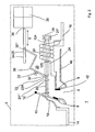
- Fig. 1 schematically a switching device 1 with a housing 2, a thermal and electromagnetic release 20 and a switching mechanism 36 is shown in the un-triggered state.
- Fig. 2 is the switching device after Fig. 1 shown in the tripped state, wherein the same or similar-acting assemblies or parts are designated by the same reference numerals.
- the contact point 4 is closed.
- a yoke 40 is still connected via an ear-shaped intermediate piece 42.
- the thermal and electromagnetic actuator 20 includes the trip coil 22 and a trip arm 24, which is here bar-shaped and arranged inside the trip coil 22 so that the coil longitudinal axis and the trip anchor longitudinal axis coincide.
- the trip arm 24 is formed of a first partial magnetic trip anchor 124 and a second partial thermal trip anchor 224 connected together at a junction 125.
- the type of connection can be positive or cohesive.
- the first partial magnetic release armature 124 is held in a trip anchor bearing 28 connected to the housing 2.
- free end 24 is the second, partial thermal release armature 224 in operative connection with a plunger 26.
- the operative connection is shown here as a positive connection, but alternatively, non-positive or cohesive connections can be realized.
- the second, partial thermal release armature 224 has a notch 25, into which engages a release lever 30 mounted in a release lever bearing 32, for example with a fork located at its first free end 30 ' End 30 "of the trigger lever 30 engages in a recess 35 in a slider 34, which is connected via a line of action 38 in operative connection with the rear derailleur 36.
- the first partial magnetic release armature 124 is made of a ferromagnetic shape memory alloy having a magnetic shape memory effect based on nickel, manganese and gallium.
- ferromagnetic shape memory alloys are known and available in principle, for example, from the Finnish company AdaptaMat Ltd. manufactured and sold.
- a typical composition of ferromagnetic shape memory alloys for use in switching devices according to the invention is given by the structural formula Ni 65-xy Mn 20 + x Ga 15 + y , where x is between 3 atomic% and 15 atomic% and y is between 3 atomic% and 12 atomic%.
- the ferromagnetic shape memory alloy used here has the property that in its martensitic phase, that is, the phase occupying the material below the thermal transition temperature, under the action of an external magnetic field on a microscopic scale, a transition between two crystal structure variants of a twin crystal structure takes place, which is macroscopic associated with a change in shape.
- the change in shape is in a linear strain in the direction of the longitudinal axis of the beam.
- the second, partial thermal release armature 224 here consists for example of a known in principle thermal shape memory alloy of nickel-titanium. With such a material, as is known, when the thermal transition temperature is exceeded, the thermal shape memory material-even without an external magnetic field-passes from its martensitic phase to its austenitic phase. This phase transition is reversible and associated with a change in shape, which also manifests itself here as a change in length of the beam-shaped second partial thermal release armature 224.
- the second partial thermal release armature 224 may also be formed of a ferromagnetic shape memory alloy of nickel, manganese, gallium differing in composition from that used in the first partial magnetic trip armature by their thermal transition temperature used ferromagnetic shape memory alloys is in the range of room temperature and is adjustable by varying the atomic percentages x and y within a bandwidth.
- the operating temperature range, within which the thermal and magnetic release operates as a purely magnetic release within a range adjustable by choice of material composition.
- the ferromagnetic shape memory material - When the thermal transition temperature is exceeded, the ferromagnetic shape memory material - even without external magnetic field - passes into its austenitic phase and behaves in this respect similar to a conventional thermal shape memory metal based on nickel and titanium.
- the ferromagnetic shape memory alloy of the first partial magnetic trip armature 124 is thus assembled to ensure effective magnetic interaction, whereas the ferromagnetic shape memory alloy of the second partial thermal trip armature 224 is selected such that the thermal transition temperature is within the desired range Consideration for the efficiency of the magnetic interaction.
- the short-circuit current tripping now happens as follows. If a high short-circuit current flows through the switching device 2 in the event of a short circuit, then the first partial magnetic release armature 124 expands due to the magnetic shape memory effect described above.
- the second thermal trip trigger armature 224 does not change in length, but is carried along by the expanding first partial magnetic trip armature 124, and as a result, the plunger 26 deflects the movable contact piece 6 away from the fixed contact 8 so that the pad 4 is opened and the switching device is triggered, as in Fig. 2 shown.
- the expansion of the ferromagnetic shape memory material happens very quickly and almost without delay.
- the delay time as the time difference between the occurrence of the short-circuit current and the maximum length of the trip armature 24 is typically on the order of one millisecond.
- the triggering is supported here by the release lever 30, which rotates in the extension of the trigger armature 24 in a clockwise direction about the trigger lever bearing 32 while the slider 34 in its longitudinal direction, indicated by the direction arrow S, shifts, so that the slide 34 on the Wirkline 38, the switching mechanism 36 is operated, which keeps the contact permanently open via active connections, not shown here.
- the current path is interrupted and the magnetic field of the tripping coil 22 breaks down again.
- the first partial magnetic release armature 124 will retract to its original dimensions, taking with it the second partial thermal release armature, which will also cause the trip lever 30 to return to the home position, as in FIG Fig. 1 shown, moved back.
- the contact point 4 is now kept permanently in the open position due to the active connections, not shown here by the switching mechanism 36.
- the thermal overcurrent tripping occurs as follows: If the current flowing in the current path through the switching device 1 exceeds its nominal value by a higher value and for a longer period than allowed, the second partial thermal release armature 224 heats up from the tripping coil 22 to one due to the heat radiation Temperature, which is above the thermal transition temperature of the thermal shape memory metal. As a result, the thermally induced shape change of the second partial thermal release armature 224 occurs, which occurs here also manifested as a longitudinal extension. The first, partial magnetic release armature 124 does not change its length because the magnetic field in the overcurrent case is insufficient.
- the release lever 30 rotates clockwise about the trigger lever bearing 32 and displaces the slider 34 in its longitudinal direction, indicated by the directional arrow S, so that the slide 34 via the line of action 38, the rear derailleur 36 is actuated, which opens the contact point via active connections, not shown here and keeps permanently open.
- the electromagnetic and the thermal tripping are thus effected by a single functional component, which is formed of two functionally different, cooperating zones.
- the construction of a switching device with a thermal and magnetic release as described is thus very simple and cheaper due to the omission of a complete assembly than conventional switching devices.
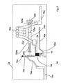
- Fig. 3 is a further embodiment of a switching device 1a according to the invention in non-tripped state, and in Fig. 4 the switching device 1a shown in a triggered state.
- Identical or equivalent components and parts are given the same reference numerals as in FIGS Fig. 1 and 2 , supplemented by the letter a.
- the essential difference between the switching device 1a according to Fig. 3 and 4 and the switching device 1 according to Fig. 1 and 2 that is, in the former, the trip armature 24a is disposed with the first partial magnetic trip armature 124a and the second partial thermal trip armature 224a external to the trip coil 22a.
- the release lever 30a, the slider 34a and the derailleur 36a in the Fig. 3 and 4 for the sake of clarity not shown.
- the switch lever 30a, the slider 34a and the derailleur 36a in the Fig. 3 and 4 for the sake of clarity not shown.
- the derailleur 36a in short-circuit current case, the
- a corresponding design of the trip coil 22a and the magnetic circuit can be made by a person skilled in the art with the aid of his normal knowledge and supported by systematic experiments.
- the heating of the second, partial thermal release armature 224 is also carried out by thermal radiation from the trip coil 22nd
- Fig. 5 is a further embodiment of a switching device 1b according to the invention in non-tripped state and in Fig. 6 the switching device 1 b shown in a triggered state.
- the same or equivalent components and parts are denoted by the same reference numerals as in the switching device 1 in the Fig. 1 and 2 , supplemented by the letter b.
- the first partial magnetic release armature 124b is formed as a sheet metal strip made of a ferromagnetic shape memory alloy.
- the second, partial thermal release armature 224b is formed as a sheet metal strip made of a thermal shape memory alloy or a - known per se - bimetallic strip.
- the two metal strips of the first, magnetic partial release armature 124b and the second partial thermal release armature 224b are connected to each other in a form, force or material fit, so that bending of the two partial release anchors bends the release armature 24b as a whole.
- the trigger anchor 24b With a first, fixed end 24b ', the trigger anchor 24b is fixedly clamped on one side to the trigger anchor bearing 28b, so that it acts as a bending beam as a whole.
- the tripping armature 24b is disposed inside the tripping coil 22b.
- the change in shape induced by the magnetic field of the tripping coil 22b in the event of a short circuit here is a bending of the first, magnetic partial tripping armature 124b, and the change in shape induced by temperature increase due to thermal radiation from the tripping coil 22b here is a deflection of the second partial thermal tripping armature 224b, respectively at the second, free end 24b ", see Fig.
- the second, free end 24b "of the release armature 24b engages in a recess 35b in a first leg 33b of the L-shaped slider 34b, whereby this upon bending of the release armature 24b in the direction of the longitudinal extension direction of the first leg 33b, indicated by the directional arrow S,
- the slide 34b is in operative connection with the plunger 26b, which, when the slide 34b is displaced, deflects the movable contact 6b away from the fixed contact 8b, thereby opening the contact point 4b of the Fig. 5 and 6 for the sake of clarity not shown.
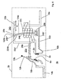
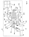
- Fig. 7 is a further embodiment of a switching device 1c according to the invention in non-tripped state and in Fig. 8 the switching device 1 c shown in a triggered state.
- the same or equivalent components and parts are denoted by the same reference numerals as in the switching device 1 in the Fig. 1 and 2 , supplemented by the letter c.
- the main difference between the switching device 1c according to Fig. 7 and 8th and the switching device 1 according to Fig. 1 and 2 is that in the former of the trigger armature 24c formed spirally and is guided inside the trigger coil 24c in a parallel to the coil axis aligned guide sleeve 23c.
- first magnetic trip striker coil 124c It is formed of a first magnetic trip striker coil 124c, and a second partial thermal trip striker coil 224c. Both partial trigger armature spirals 124c and 224c are arranged one behind the other and are connected to one another at the connection point 125c in a positive, non-positive or cohesive manner.
- the first partial release magnetic magnetic coil 124c is made of a ferromagnetic shape memory alloy having a magnetic shape memory effect based on nickel, manganese and gallium.
- the second, partial thermal release armature spiral 224c here consists, for example, of a thermal shape memory alloy of nickel-titanium, or of a thermobimetal, known in principle.
- the change in shape of the helical trigger armature 24c induced by the magnetic field of the tripping coil 22c in the event of a short circuit or by temperature increase of the tripping armature 24c due to thermal radiation from the tripping coil 22c here in the first case lies in an extension of the first, magnetic partial tripping armature coil 124c, as a result of which second partial thermal release armature coil 224c is displaced, or in the second case in an extension of the second partial thermal release armature coil 224c, and thus in each case in an integral extension of the trigger armature spiral 24c in the direction of the spiral longitudinal axis, indicated by the directional arrow L.
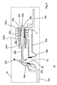
- Fig. 9 is a further embodiment of a switching device 1d according to the invention in non-tripped state
- Fig. 10 is the switching device 1d in a triggered state shown.
- the same or equivalent components and parts are denoted by the same reference numerals as in the switching device 1 in the Fig. 1 and 2 , supplemented by the letter d.
- FIG. 9 The embodiment shown differs from that in FIG Fig. 1 in that, in the former, the heating of the release armature 24d takes place directly by current flow and not, as with the latter, indirectly via thermal radiation from the release coil 22d.
- the current path in the embodiment according to Fig. 9 is as follows: from the input terminal 14d, the current flows through the movable wire 18d, the contact lever 10d. the pad 4d passes through the trip coil 22d and further in series therewith via another movable lead 18d 'which electrically connects the end of the trip coil 22d to the second partial thermal trip armature 224d through it and the first partial magnetic trip arm 124d through and from its fixed end 24d 'on to the output terminal 16d.
- the first partial thermal release armature 224d is thus directly heated by current heat.
- a thermally more accurate design of the thermal and magnetic release 20d is possible.
- a return spring 46d provided in support of the re-deformation of the release armature 24d after tripping in the short-circuit current case after breakdown of the magnetic field of the tripping coil 22d or in the event of overcurrent after cooling of the tripping armature 24d to a temperature below the thermal transition temperature due to the contact opening - Fig. 9 and 10 .
- This is designed here as a spiral spring and includes the plunger 26d. But it could also be designed as a leaf spring or in any other suitable manner.
- the return spring is in a non-triggered state ( Fig. 9 ) relaxed. It is supported at one end to a spring bearing 50d connected to the housing, and at its other end to the movable end 24d "of the trigger armature 24d. Fig. 10 ) it is compressed by the expanding trigger anchor 24d.
- FIG. 1 to 10 Illustrated and described embodiments are an exemplary, non-exhaustive representation of possible inventive switching devices using a thermal and electromagnetic release with a trigger armature of a first, magnetic partial trip anchor and a second, partial thermal tripping anchor. It can also from all others in the state Known in the art switchgear variants with thermal and electromagnetic triggers are produced by the inventive use of a ferromagnetic shape memory alloy in a first, magnetic partial tripping armature of a first, magnetic partial tripping armature and a second, partial tripping trigger trip triggered tripping armature according to the invention.
Landscapes
- Physics & Mathematics (AREA)
- Electromagnetism (AREA)
- Breakers (AREA)
- Thermally Actuated Switches (AREA)
- Electromagnets (AREA)
- Portable Nailing Machines And Staplers (AREA)
Description
- Die Erfindung betrifft ein Schaltgerät mit einem Gehäuse und mit wenigstens einer ein festes Kontaktstück und ein bewegliches Kontaktstück umfassenden Kontaktstelle, und mit einem thermischen und magnetischen Auslöser mit einer Auslösespule und einem die Kontaktstelle öffnenden Auslöseanker, gemäß dem Oberbegriff des Anspruchs 1. Ein solches Schaltgerät, wobei ein Teil des Auslöseankers aus einem Material mit thermischem Formgedächtniseffekt gebildet ist, ist in der
DE 94 05 745 U1 offenbart. Weiter betrifft die Erfindung die Verwendung eines Materials mit einem magnetischen Formgedächtniseffekt in einem eine Auslösespule und einen Auslöseanker aufweisenden thermisch-elektromagnetischen Auslöser für ein Schaltgerät gemäß dem Oberbegriff des Anspruchs 13, sowie weiterhin die Verwendung eines Materials mit einem magnetischen Formgedächtniseffekt zur Überstrom- und Kurzschlussstromauslösung in einem eine Kontaktstelle und einen thermisch-elektromagnetischen Auslöser umfassenden Schaltgerät gemäß dem Oberbegriff des Anspruchs 16. - Bei gattungsgemäßen Schaltgeräten, beispielsweise Leitungsschutzschaltern oder Motorschutzschaltern, dient der elektromagnetische Auslöser zur Unterbrechung des Strompfades zwischen den Ein- und Ausgangsklemmen im Falle des Auftretens eines Kurzschlussstromes. Der thermische Auslöser dient zur Unterbrechung des Strompfades für den Fall, dass ein Überstrom auftritt, der den Nennstrom um einen bestimmten Betrag und über eine bestimmte Zeit hinweg überschreitet. Die im Stand der Technik heute bekannten elektromagnetischen Auslöser, wie beispielsweise in der
DE 101 26 852 C1 oder derDE 100 10 093 A1 beschrieben, arbeiten dabei alle nach dem Prinzip, dass ein Auslöseanker bei Auftreten eines Kurzschlussstromes auf einen Magnetkern hin in Bewegung versetzt wird, und im Verlauf dieser Bewegung schlägt der Auslöseanker über einen mit ihm in Wirkverbindung stehenden Stößel das bewegliche Kontaktstück von dem festen Kontaktstück an der Kontaktstelle weg, so dass dadurch die Kontaktstelle geöffnet wird. Bekannte elektromagnetische Auslöser umfassen dazu eine Spule, die üblicherweise aus schraubenförmig gewickeltem Draht hergestellt ist, sowie einen mit einem die Spule außen umgebenden Joch fest verbundenen Magnetkern, der ins Innere der Spule eingreift. Der Auslöseanker ist entweder als Klappanker oder als Tauchanker ausgebildet, wobei sich letzterer ebenfalls innerhalb der Spule befindet. Der Anker wird vom Kern im Ruhezustand mittels einer Druckfeder auf Abstand gehalten. Wenn der Kurzschlussstrom durch die Auslösespule fließt, so bewirkt das dabei erzeugte Magnetfeld der Auslösespule, dass der Auslöseanker entgegen der rückstellenden Kraft der Druckfeder auf den Kern hin bewegt wird. Nach Abschalten des Kurzschlussstromes wird der Anker durch die rückstellende Kraft der Druckfeder wieder in seine Ausgangslage zurückbewegt. - Im Stand der Technik bekannte thermische Auslöser arbeiten in der Regel mit Auslöseelementen aus Thermobimetall oder thermischen Formgedächtnismetallen, die beispielsweise als Biegebalken oder als Schnappscheibe realisiert sind. Aus der
DE 43 00 909 A1 ist ein thermischer Auslöser mit einem Thermobimetall-Biegebalken bekannt. - Thermische und magnetische Auslöser werden heute aus einem ersten, thermischen Teil-Auslöser mit einem thermischen Auslöseanker aus Thermobimetall oder thermischem Formgedächtnismetall, wie oben erwähnt, und einem zweiten, magnetischen Teil-Auslöser mit einer Auslösespule und einem magnetischen Auslöseanker zusammengesetzt. Aus der
DE 42 42 516 A1 ist ein thermisch-magnetischer Kombi-Auslöser bekannt, bei dem der thermische Teil-Auslöser als Schnappscheibe und der elektromagnetische Teil-Auslöser durch einen Schlaganker-Auslöser ausgebildet ist. Aber auch hier sind zwei getrennte Auslöser aufgebaut, die räumlich nahe beieinander in einer komplexen Baugruppe kombiniert sind. - Der Aufbau thermischer und elektromagnetischer Auslöser ist daher heute sehr aufwändig und mit hohen Kosten verbunden, da zwei komplette Auslöser aufgebaut und miteinander kombiniert werden müssen, wobei in viele Einzelteile mit engen Toleranzen gefertigt und zusammen zu bauen sind.
- Es ist daher die Aufgabe der vorliegenden Erfindung, ein gattungsgemäßes Schaltgerät einfacher montierbar und damit kostengünstiger aufzubauen.
- Die Aufgabe wird gelöst durch ein Schaltgerät mit den kennzeichnenden Merkmalen des Anspruchs 1, durch die Verwendung eines Materials mit einem kombinierten thermischen und magnetischen Formgedächtniseffekt in einem Schaltgerät gemäß den kennzeichnenden Merkmalen des Anspruchs 13 und durch die Verwendung eines Materials mit einem kombinierten thermischen und magnetischen Formgedächtniseffekt zur Kurzschluss- und Überstromstromauslösung in einem Schaltgerät gemäß den kennzeichnenden Merkmalen des Anspruchs 16.
- Erfindungsgemäß also umfasst der Auslöseanker zwei in Wirkverbindung stehende Teil-Auslöseanker, und ein erster Teil-Auslöseanker ist aus einem ersten Material mit einem magnetischen Formgedächtniseffekt gebildet, und ein zweiter Teil-Auslöseanker ist aus einem Thermobimetall oder aus einem Material mit thermischem Formgedächtniseffekt oder aus einem Material mit kombiniertem thermischen und magnetischem Formgedächtniseffekt gebildet ist, wobei sowohl unter Einfluss des Magnetfeldes der Auslösespule im Kurzschlussstromfall, als auch unter Einfluss einer durch Überstrom hervorgerufenen Temperaturerhöhung der Auslöseanker verformt und dadurch die Öffnung der Kontaktstelle bewirkt wird.
- Bei magnetischen Formgedächtnislegierungen kann in der martensitischen Phase eine Formänderung durch den Übergang zwischen zwei Kristallstrukturvarianten einer Zwilings-Kristallstruktur hervorgerufen werden, wobei der Übergang zwischen den Kristallstrukturvarianten durch ein äußeres Magnetfeld gesteuert wird. Diese Materialien werden daher als magnetische Formgedächtnislegierungen oder "Magnetic Shape Memory Alloys" (MSM) bezeichnet.
- Bei den bekannten thermischen Formgedächtnislegierungen, hier auch als "Thermal Shape Memory Alloys (TSM) bezeichnet, z.B. auf Basis Ni-Ti, sind die beiden Formen, zwischen denen das Bauteil wechselt, in unterschiedlichen Phasen des Materials ausgeformt: einer martensitischen Phase unterhalb und einer austenitischen Phase oberhalb einer sog. Transitionstemperatur des Materials. Überschreitet die Materialtemperatur die Transitionstemperatur, so findet der Phasenübergang statt, mit dem die Formänderung einhergeht
- Insofern unterscheiden sich die thermischen Formgedächtnislegierungen in ihrer Funktionsweise von den ebenfalls bekannten Thermobimetallen. Ein Thermobimetall-Blech besteht nämlich aus zwei zusammengeschweißten Metallenblechen unterschiedlicher thermischer Ausdehnungskoeffizienten. Bei Erwärmung dehnt sich die eine Seite des Thermobimetalls stärker aus als die andere, so dass sich das Thermobimetall-Blech insgesamt in Richtung auf das Material mit dem kleineren Wärmeausdehnungskoeffizienten hin verbiegt.
- Magnetische Formgedächtnislegierungen werden vorteilhafterweise als ferromagnetische Formgedächtnislegierungen aus Nickel, Mangan und Gallium gebildet. Genauere Erläuterungen zum Aufbau und der Funktionsweise von ferromagnetischen Formgedächtnislegierungen auf der Basis von Nickel, Mangan und Gallium sind beispielsweise der
WO 98/08261 WO 99/45631 - Durch die entsprechende Legierungszusammensetzung kann bestimmt werden, bei welcher Orientierung des äußeren Magnetfeldes die maximale Ausdehnung erreicht wird; z.B. kann das Magnetfeld senkrecht oder quer zu dem MSM - Material stehen, um die maximale Ausdehnung zu erreichen.
- Formänderungen, die mit MSM-Materialien unter Einwirken eines äußeren Magnetfeldes erreicht werden, können lineare Ausdehnung, Verbiegung oder Verdrehung (Torsion) sein.
- Bei MSM-Materialien findet ergänzend zu dem magnetisch stimulierten auch noch ein thermisch stimulierter Übergang zwischen der martensitischen und der austenitischen Phase statt.
- Wenn das äußere Magnetfeld hinreichend klein ist, so verhalten sich diese Materialien wie ein herkömmliches thermisches Formgedächtnismetall. Dabei kann durch die entsprechende Legierungszusammensetzung die thermische Transitionstemperatur bestimmt und somit für die jeweilige Anwendung angepasst werden.
- Bei MSM - Materialien kann somit unterhalb der Transitionstemperatur, in der Niedertemperatur- oder martensitischen Phase, eine der o.g. Formänderungen ausschließlich durch Anlegen eines äußeren Magnetfeldes hervorgerufen werden. Ohne äußeres Magnetfeld, oder bei sehr geringem äußerem Magnetfeld, erfolgt die Formänderung thermisch induziert bei Über- oder Unterschreiten der Transitionstemperatur.
- Der Vorteil der Erfindung liegt darin, dass bei einem erfindungsgemäßen Schaltgerät beide Auslöseprinzipien, nämlich das thermische und das elektromagnetische, in einem einzigen Auslöseelement niedriger Komplexität realisiert sind. Damit wird der Aufbau eines thermischen und magnetischen Auslösers stark vereinfacht. Der erfindungsgemäße thermische und magnetische Auslöser lässt sich auch wesentlich kompakter und platzsparender realisieren als eine Kombination von zwei getrennten thermischen und magnetischen Auslösern gemäß dem Stand der Technik. Somit ist auch ein erfindungsgemäßes Schaltgerät mit einem erfindungsgemäßen thermischen und magnetischen Auslöser einfacher und kompakter aufbaubar.
- Ein weiterer Vorteil eines erfindungsgemäßen Schaltgerätes ist die Schnelligkeit der magnetischen Auslösung. Es muß keine träge Masse beschleunigt werden, die Formänderung aufgrund des magnetischen Formgedächtniseffektes geschieht nahezu verzögerungsfrei.
- Vorteilhaft ist auch die Erreichbarkeit einer hohen Stellkraft bei relativ großer Längenänderung aufgrund der hohen magnetisch-mechanischen Energiewandlungseffizienz bei ferromagnetischen Formgedächtnislegierungen.
- Bei dem erfindungsgemäßen Schaltgerät kann das Magnetfeld für die elektromagnetische Auslösung durch eine stromdurchflossene Spule erzeugt werden.
- In einer vorteilhaften Ausführungsform der Erfindung sind der erste und zweiteTeil-Auslöseanker aus ferromagnetischen Formgedächtnislegierungen aus Nickel, Mangan und Gallium mit jeweils unterschiedlichen Zusammensetzungen gebildet.
- Der erste, magnetische und der zweite, thermische Teil-Auslöseanker können vorteilhafterweise als längserstreckte Bauteile ausgebildet sein, wobei unter dem Einfluss des Magnetfeldes der Auslösespule im Kurzschlussstromfall der erste Teil-Auslöseanker und unter Einfluss einer durch Überstrom hervorgerufenen Temperaturerhöhung der zweite Teil-Auslöseanker in Richtung ihrer Längsachse gedehnt werden. Der erste Teil-Auslöseanker ist beispielsweise mit dem zweiten Teil-Auslöseanker formschlüssig verbunden, so dass insgesamt ein zweiteiliger Auslöseanker gebildet wird, dessen einer Teil aus dem thermischen und dessen anderer Teil aus dem magnetischen Formgedächtnismaterial besteht. Auch andere Arten einer Wirkverbindung zwischen dem magnetischen und dem thermischen Anker sind denkbar. Wichtig ist, dass der zweite, thermische und der erste, magnetische Teil-Anker beide unabhängig voneinander ihre Form ändern können, so dass der Auslöseanker insgesamt sowohl magnetisch als auch thermisch aktiviert auf die Kontaktstelle des Installationsschaltgerätes einwirken kann.
- Der erste und zweite Teil-Auslöseanker können auch balkenförmig ausgebildet sein, wobei unter dem Einfluss des Magnetfeldes der Auslösespule im Kurzschlussstromfall der erste Teil-Auslöseanker und unter Einfluss einer durch Überstrom hervorgerufenen Temperaturerhöhung der zweite Teil-Auslöseanker verbogen werden. Der Erste Teil-Auslöseanker kann dabei aus einem Streifen einer ferromagnetischen Formgedächtnislegierung bestehen, an dessen Breitseite formschlüssig ein Thermobimetall-Streifen angebracht ist.
- Eine weitere vorteilhafte mögliche Ausgestaltungsform ist so aufgebaut, dass der erste und zweite Teil-Auslöseanker spiralförmig ausgebildet sind, wobei unter dem Einfluss des Magnetfeldes der Auslösespule im Kurzschlussstromfall der erste Teil-Auslöseanker und unter Einfluss einer durch Überstrom hervorgerufenen Temperaturerhöhung der zweite Teil-Auslöseanker in Richtung der Spiralenlängsachse gedehnt werden.
- Der Auslöseanker kann dabei an seinem zweiten Ende in Wirkverbindung mit einem Stößel stehen. Auch ist die Lagerung des erfindungsgemäßen Auslöseankers aus ferromagnetischem Formgedächtnismetall einfacher als die Lagerung des Auslöseankers bei herkömmlichen Auslösern. Denn dort muss der Auslöseanker leicht beweglich gelagert sein, wohingegen er bei erfindungsgemäßen Auslösern keine beweglichen Teile mehr umfasst und in einer vorteilhaften Ausführungsform an einem ersten Ende fest gelagert ist, wobei er sich an seinem zweiten, beweglichen Ende unter Einwirkung sowohl des Magnetfeldes als auch einer überstrombedingten Temperaturerhöhung ausdehnt oder verbiegt Vorteilhaft ist dabei insbesondere eine Ausführungsform, bei der der Auslöseanker an einem ersten, festen Ende in einem mit dem Gehäuse verbundenem Lager gehalten ist.
- In einer vorteilhaften Ausführungsform des erfindungsgemäßen thermischen und magnetischen Auslösers wird die Temperaturerhöhung des Auslöseankers, insbesondere des zweiten, thermischen Teil-Auslöseankers, im Überstromfall mittels indirekter Erwärmung bewirkt. Der Überstrom durchfließt dazu beispielsweise die Auslösespule, in deren Nahbereich der Auslöseanker angebracht ist. Bei Erwärmung der Spule infolge Überstrom wird der Auslöseanker, insbesondere der zweite, thermische Teil-Auslöseanker, durch Wärmestrahlung indirekt mit erwärmt.
- Eine weitere vorteilhafte Ausführungsform ist dadurch gekennzeichnet, dass die Temperaturerhöhung des Auslöseankers, insbesondere des zweiten, thermischen Teil-Auslöseankers, im Überstromfall durch direkte Erwärmung bewirkt wird. Der Auslöseanker wird dabei direkt vom Überstrom durchflossen, und durch aufgrund der durch den Stromfluss induzierten Widerstandserwärmung heizt sich der Auslöseanker, insbesondere der zweite, thermische Teil-Auslöseanker, auf.
- Ein großer Vorteil eines efindnungsgemäßen Schaltgerätes liegt darin, dass die räumliche Zuordnung der Auslösespule zu dem Auslöseanker aus ferromagnetischem Formgedächtnismetall vielfältig an die Geometrieerfordernisse innerhalb des Schaltgerätegehäuses anpassbar ist. So kann in einer vorteilhaften Ausführungsform der Auslöseanker von der Auslösespule umfasst sein. Gemäß einer weiteren vorteilhaften Ausführungsform kann der Auslöseanker außerhalb der Spule in deren Nahbereich angebracht sein.
- Ein zusätzliches weiteres thermisches Auslöseelement ist nicht nötig.
- Somit ist eine optimale Raumausnutzung innerhalb des Schaltgerätegehäuses erreichbar, was zu kleineren und damit kostengünstigeren Bauformen der Schaltgeräte führt.
- Es werden weniger Teile mit geringerer Anforderung an deren Maßgenauigkeit für den thermischen und elektromagnetischen Auslöser benötig, und die Montage eines thermischen und elektromagnetischen Auslösers mit einem Auslöseanker aus ferromagnetischem Formgedächtnismetall ist daher einfacher und billiger.
- Weitere vorteilhafte Ausgestaltungen und Verbesserungen der Erfindung und weitere Vorteile sind den weiteren Unteransprüchen zu entnehmen.
- Anhand der Zeichnungen, in denen fünf Ausführungsbeispiele der Erfindung dargestellt sind, sollen die Erfindung sowie weitere vorteilhafte Ausgestaltungen der Erfindung näher erläutert und beschrieben werden.
- Es zeigen:
- Fig. 1
- in schematischer Darstellung eine erste Ausführungsform eines erfindungsgemäßen Schaltgerätes mit einem stabförmigen Auslöseanker, gebildet aus einem ersten, magnetischen Teil-Auslöseanker aus ferromagnetischem Formgedächtnismetall und einem zweiten, thermischen TeilAuslöseanker aus thermischem Formgedächtnismetall, angeordnet im Innenraum einer Auslösespule, im Ruhezustand,
- Fig. 2
- in schematischer Darstellung die erste Ausführungsform nach
Fig. 1 im ausgelösten Zustand, - Fig. 3
- in schematischer Darstellung eine zweite Ausführungsform eines erfindungsgemäßen Schaltgerätes mit einem stabförmigen Auslöseanker, gebildet aus einem ersten, magnetischen Teil-Auslöseanker aus ferromagnetischem Formgedächtnismetall und einem zweiten, thermischen Teil-Auslöseanker aus thermischem Formgedächtnismetall, angeordnet neben einer Auslösespule, im Ruhezustand,
- Fig. 4
- in schematischer Darstellung die zweite Ausführungsform nach
Fig. 3 im ausgelösten Zustand, - Fig. 5
- in schematischer Darstellung eine dritte Ausführungsform eines erfindungsgemäßen Schaltgerätes mit einem als einseitig eingespannter Biegebalken ausgebildeten Auslöseanker, gebildet aus einem ersten, magnetischen Teil-Auslöseanker aus einem Streifen magnetischen Formgedächtnismetalles, und einem zweiten, thermischen Teil-Auslöseanker, aus einem Streifen Thermobimetall, angeordnet im Innern einer Auslösespule, im Ruhezustand,
- Fig. 6
- in schematischer Darstellung die dritte Ausführungsform nach
Fig. 5 im ausgelösten Zustand, - Fig. 7
- in schematischer Darstellung eine vierte Ausführungsform eines erfindungsgemäßen Schaltgerätes mit einem spiralförmigen Auslöseanker, gebildet aus einem ersten, magnetischen Teil-Auslöseanker aus einer Spirale aus magnetischem Formgedächtnismetall, und einem zweiten, thermischen Teil-Auslöseanker aus einer Spirale aus Thermobimetall, angeordnet im Innern einer Auslösespule, im Ruhezustand,
- Fig. 8
- in schematischer Darstellung die vierte Ausführungsform nach
Fig. 7 im ausgelösten Zustand, sowie - Fig. 9
- in schematischer Darstellung eine fünfte Ausführungsform eines erfindungsgemäßen Schaltgerätes mit einem stromdurchflossenen stabförmigen Auslöseanker, gebildet aus einem ersten, magnetischen TeilAuslöseanker aus ferromagnetischem Formgedächtnismetall und einem zweiten, thermischen Teil-Auslöseanker aus thermischem Formgedächtnismetall , angeordnet im Innern einer Auslösespule, im Ruhezustand, sowie
- Fig. 10
- in schematischer Darstellung die fünfte Ausführungsform nach
Fig. 9 im ausgelösten Zustand. - In
Fig. 1 ist schematisch ein Schaltgerät 1 mit einem Gehäuse 2, einem thermischen und elektromagnetischen Auslöser 20 und einem Schaltwerk 36 im nicht ausgelösten Zustand gezeigt. InFig. 2 ist das Schaltgerät nachFig. 1 im ausgelösten Zustand gezeigt, wobei gleiche oder ähnlich wirkende Baugruppen oder Teile mit denselben Bezugsziffern bezeichnet sind. - Zwischen einem Eingangsklemmstück 14 und einem Ausgangsklemmstück 16 verläuft ein Strompfad über eine bewegliche Litze 18, einen in einem Kontakthebellager 12 gelagerten Kontakthebel 10, eine, ein an dem Kontakthebel 10 befindliches, bewegliches Kontaktstück 6 und ein festes Kontaktstück 8 umfassende Kontaktstelle 4, und eine Auslösespule 22. In der in
Fig. 1 gezeigten Schaltstellung ist die Kontaktstelle 4 geschlossen. Mit der Auslösespule 22 und dem festen Kontaktstück 8 ist über ein ohrenförmiges Zwischenstück 42 noch ein Joch 40 verbunden. - Der thermische und elektromagnetische Auslöser 20 umfasst die Auslösespule 22 und einen Auslöseanker 24, der hier balkenförmig ausgeführt und im Inneren der Auslösespule 22 so angeordnet ist, dass die Spulenlängsachse und die Auslöseanker-Längsachse zusammenfallen.
- Der Auslöseanker 24 ist aus einem ersten, magnetischen Teil-Auslöseanker 124 und einem zweiten, thermischen Teil-Auslöseanker 224 gebildet, die an einer Verbindungsstelle 125 miteinander verbunden sind. Die Art der Verbindung kann form- kraft- oder stoffschlüssig sein.
- An einem ersten, festen Ende 24' ist der erste, magnetische Teil-Auslöseanker 124 in einem mit dem Gehäuse 2 verbundenen Auslöseanker-Lager 28 gehalten. An seinem zweiten, freien Ende 24" steht der zweite, thermische Teil-Auslöseanker 224 in Wirkverbindung mit einem Stößel 26. Die Wirkverbindung ist hier als formschlüssige Verbindung gezeigt, alternativ könnten jedoch auch kraft- oder stoffschlüssige Verbindungen realisiert werden.
- An seinem freien Ende 24" weist der zweite, thermische Teil-Auslöseanker 224 eine Einkerbung 25 auf, in die ein in einem Auslösehebel-Lager 32 gelagerter Auslösehebel 30, beispielsweise mit einer an seinem ersten freien Ende 30' befindlichen Gabel eingreift. Das zweite freie Ende 30" des Auslösehebels 30 greift in eine Ausnehmung 35 in einem Schieber 34 ein, der über eine Wirklinie 38 in Wirkverbindung mit dem Schaltwerk 36 steht.
- Der erste, magnetische Teil-Auslöseanker 124 besteht aus einer ferromagnetischen Formgedächtnislegierung mit einem magnetischen Formgedächtniseffekt auf Basis von Nickel, Mangan und Gallium. Solche ferromagnetischen Formgedächtnislegierungen sind prinzipiell bekannt und verfügbar, sie werden beispielsweise von der finnischen Firma AdaptaMat Ltd. hergestellt und vertrieben. Eine typische Zusammensetzung von ferromagnetischen Formgedächtnis-Legierungen für den erfindungsgemäßen Einsatz in Schaltgeräten ist gegeben durch die Strukturformel Ni65-x-yMn 20+xGa15+y, wobei x zwischen 3 Atomprozent und 15 Atomprozent liegt und y zwischen 3 Atomprozent und 12 Atomprozent.
- Die hier verwendete ferromagnetische Formgedächtnislegierung hat die Eigenschaft, dass in ihrer martensitischen Phase, das ist diejenige Phase, die das Material unterhalb der thermischen Transitionstemperatur einnimmt, unter Einwirkung eines äußeren Magnetfeldes im mikroskopischen Maßstab ein Übergang zwischen zwei Kristallstrukturvarianten einer Zwillings-Kristallstruktur stattfindet, der makroskopisch mit einer Formänderung verbunden ist. Bei der hier gewählten Ausführung des Auslöseankers besteht die Formänderung in einer linearen Dehnung in Richtung der Balkenlängsachse.
- Der zweite, thermische Teil-Auslöseanker 224 besteht hier beispielsweise aus einer im Prinzip bekannten thermischen Formgedächtnislegierung aus Nickel-Titan. Bei einem solchen Material geht bekanntermaßen bei Überschreiten der thermischen Transitionstemperatur das thermische Formgedächtnismaterial - auch ohne äußeres Magnetfeld -von seiner martensitischen in seine austenitische Phase über. Dieser Phasenübergang ist reversibel und mit einer Formänderung verbunden, welche sich hier ebenfalls als eine Längenänderung des balkenförmigen zweiten, thermischen Teil-Auslöseankers 224 manifestiert.
- Der zweite, thermische Teil-Auslöseanker 224 kann aber auch aus einer ferromagnetischen Formgedächtnislegierung aus Nickel, Mangan, Gallium gebildet sein, die sich in ihrer Zusammensetzung von derjenigen im ersten, magnetischen Teil-Auslöseanker verwendeten durch ihre thermische Transitionstemperatur unterscheidet Die thermische Transitionstemperatur bei den hier verwendeten ferromagnetischen Formgedächtnislegierungen liegt im Bereich der Raumtemperatur und ist durch Variation der Atomprozent-Anteile x und y innerhalb einer Bandbreite einstellbar. Damit ist der Arbeitstemperaturbereich, innerhalb dessen der thermische und magnetische Auslöser als rein magnetischer Auslöser arbeitet, innerhalb einer Bandbreite durch Wahl der Materialzusammensetzung einstellbar.
- Bei Überschreiten der thermischen Transitionstemperatur geht das ferromagnetische Formgedächtnismaterial - auch ohne äußeres Magnetfeld - in seine austenitische Phase über und verhält sich insofern ähnlich wie ein herkömmliches thermisches Formgedächtnismetall auf Basis von Nickel und Titan. Die ferromagnetische Formgedächtnislegierung des ersten, magnetischen Teil-Auslöseankers 124 ist demnach so zusammengesetzt, dass eine effektive magnetische Wechselwirkung gewährleistet ist, wohingegen die ferromagnetische Formgedächtnislegierung des zweiten, thermischen Teil-Auslöseankers 224 so gewählt ist, dass die thermische Transitionstemperatur im gewünschten Bereich liegt, ohne Rücksicht auf die Effizienz der magnetischen Wechselwirkung.
- Die Kurzschlussstromauslösung geschieht nun folgendermaßen. Fließt durch das Schaltgerät 2 im Kurzschlussfall ein hoher Kurzschlussstrom, so dehnt sich der erste, magnetische Teil-Auslöseanker 124 aufgrund des oben beschriebenen magnetischen Formgedächtniseffektes aus. Der zweite, thermische Teil-Auslöseanker 224 ändert seine Länge nicht, wird aber von dem sich ausdehnenden ersten, magnetischen Teil-Auslöseanker 124 mitgenommen, und infolgedessen schlägt der Stößel 26 das bewegliche Kontaktstück 6 vom festen Kontaktstück 8 weg, so dass die Kontaktstelle 4 geöffnet und das Schaltgerät ausgelöst wird, wie in
Fig. 2 dargestellt. Die Ausdehnung des ferromagnetischen Formgedächtnismaterials geschieht dabei sehr schnell und nahezu verzögerungsfrei. Die Verzögerungszeit als die Zeitdifferenz zwischen dem Auftreten des Kurzschlussstromes und der maximalen Längenausdehnung des Auslöseankers 24 liegt typischerweise in der Größenordnung von einer Millisekunde. - Die Auslösung wird hier durch den Auslösehebel 30 unterstützt, der bei Ausdehnung des Auslöseankers 24 sich im Uhrzeigersinn um das Auslösehebel-Lager 32 dreht und dabei den Schieber 34 in dessen Längserstreckungsrichtung, angedeutet durch den Richtungspfeil S, verschiebt, so dass der Schieber 34 über die Wirklinie 38 das Schaltwerk 36 betätigt, das die Kontaktstelle über hier nicht dargestellte Wirkverbindungen dauerhaft geöffnet hält.
- Nach der Auslösung des Schaltgerätes ist der Strompfad unterbrochen und das Magnetfeld der Auslösespule 22 bricht wieder zusammen. Infolgedessen wird sich der erste, magnetische Teil-Auslöseanker 124 wieder auf seine Ausgangsmaße zusammenziehen und dabei den zweiten, thermischen Teil-Auslöseanker mitnehmen, wodurch auch der Auslösehebel 30 wieder in die Ausgangsstellung, wie in
Fig. 1 gezeigt, zurückbewegt wird. Die Kontaktstelle 4 wird jetzt aufgrund der hier nicht dargestellten Wirkverbindungen durch das Schaltwerk 36 dauerhaft in Offenstellung gehalten. - Die thermische Überstromauslösung geschieht folgendermaßen: Überschreitet der im Strompfad durch das Schaltgerät 1 fließende Strom seinen Nennwert um einen höheren Wert und für einen längeren Zeitraum als zugelassen, so erwärmt sich der zweite, thermische Teil-Auslöseanker 224 aufgrund der Wärmeeinstrahlung von der Auslösespule 22 auf eine Temperatur, die oberhalb der thermischen Transitionstemperatur des thermischen Formgedächtnismetalls liegt. Infolgedessen findet die thermisch induzierte Formänderung des zweiten, thermischen Teil-Auslöseankers 224 statt, die sich hier ebenfalls als eine Längenausdehnung manifestiert. Der erste, magnetische Teil-Auslöseanker 124 ändert seine Länge nicht, da das Magnetfeld im Überstromfall dazu nicht ausreicht. Durch die Ausdehnung des zweiten, thermischen Teil-Auslöseankers 224 und infolge des Eingriffs dessen ersten freien Endes 30' dreht sich der Auslösehebel 30 im Uhrzeigersinn um das Auslösehebel-Lager 32 und verschiebt dabei den Schieber 34 in dessen Längserstreckungsrichtung, angedeutet durch den Richtungspfeil S, so dass der Schieber 34 über die Wirklinie 38 das Schaltwerk 36 betätigt, das die Kontaktstelle über hier nicht dargestellte Wirkverbindungen öffnet und dauerhaft geöffnet hält.
- Die elektromagnetische und die thermische Auslösung werden also von einem einzigen Funktionsbauelement bewirkt, das aus zwei funktionell unterschiedlichen, zusammenwirkenden Zonen gebildet ist. Der Aufbau eines Schaltgerätes mit einem thermischen und magnetischen Auslöser wie beschrieben wird damit sehr einfach und aufgrund des Entfallens einer kompletten Baugruppe kostengünstiger als bei herkömmlichen Schaltgeräten.
- In
Fig. 3 ist eine weitere Ausführungsform eines erfindungsgemäßen Schaltgerätes 1a in nicht ausgelöstem Zustand, und inFig. 4 das Schaltgerät 1a in ausgelöstem Zustand gezeigt. Gleiche oder gleichwirkende Baugruppen und Teile sind mit denselben Bezugsziffern wie in denFig. 1 und2 , ergänzt um den Buchstaben a, bezeichnet. Der wesentliche Unterschied zwischen dem Schaltgerät 1a gemäßFig. 3 und4 und dem Schaltgerät 1 gemäßFig. 1 und2 besteht darin, dass bei ersterem der Auslöseanker 24a mit dem ersten, magnetischen Teil-Auslöseanker 124a und dem zweiten, thermischen Teil-Auslöseanker 224a außerhalb der Auslösespule 22a angeordnet ist. Außerdem sind der Auslösehebel 30a, der Schieber 34a und das Schaltwerk 36a in denFig. 3 und4 der Übersichtlichkeit halber nicht dargestellt. Im Kurzschlussstromfall wird die - Formänderung des ersten, magnetischen Teil-Auslöseankers 124a bei der in den
Fig. 3 und4 gezeigten Ausführungsform durch das Magnetfeld im Außenbereich der Auslösespule 22a bewirkt. Eine entsprechende Auslegung der Auslösespule 22a und des Magnetkreises kann von einem Fachmann unter Zuhilfenahme seines normalen Fachwissens und unterstützt durch systematische Versuche vorgenommen werden. Im thermischen Überlastfall erfolgt die Erwärmung des zweiten, thermischen Teil-Auslöseankers 224 ebenfalls durch Wärmestrahlung von der Auslösespule 22. - In
Fig. 5 ist eine weitere Ausführungsform eines erfindungsgemäßen Schaltgerätes 1b in nicht ausgelöstem Zustand und inFig. 6 das Schaltgerät 1 b in ausgelöstem Zustand gezeigt. Gleiche oder gleichwirkende Baugruppen und Teile sind mit denselben Bezugsziffern wie beim Schaltgerät 1 in denFig. 1 und2 , ergänzt um den Buchstaben b, bezeichnet. Der wesentliche Unterschied zwischen dem Schaltgerät 1 b gemäßFig. 5 und6 und dem Schaltgerät 1 gemäßFig. 1 und2 besteht darin, dass der Auslöseanker 24b mit dem ersten, magnetischen Teil-Auslöseanker 124b und dem zweiten, thermischen Teil-Auslöseanker 224b bei ersterem als Biegebalken ausgeführt ist. Der erste, magnetische Teil-Auslöseanker 124b ist als Blechstreifen aus einer ferromagnetischen Formgedächtnislegierung gebildet. Der zweite, thermische Teil-Auslöseanker 224b ist als Blechstreifen aus einer thermischen Formgedächtnislegierung oder aus einem - an sich bekannten - Thermobimetall gebildet. Die beiden Blechstreifen des ersten, magnetischen Teil-Auslöseankers 124b und des zweiten, thermischen Teil-Auslöseankers 224b sind an einer Breitseite miteinanderform-, kraft- oder stoffschlüssig verbunden, so dass eine Verbiegung deines der beiden Teil-Auslöseanker den Auslöseanker 24b insgesamt verbiegt. Mit einem ersten, festen Ende 24b' ist der Auslöseanker 24b einseitig an der Auslöseanker-Lagerstelle 28b fest eingespannt, so dass er insgesamt als Biegebalken wirkt. Der Auslöseanker 24b ist im Innenraum der Auslösespule 22b angeordnet. Die durch das Magnetfeld der Auslösespule 22b im Kurzschlussfall induzierte Formänderung besteht hier in einer Verbiegung des ersten, magnetischen Teil-Auslöseankers 124b, und die durch Temperaturerhöhung aufgrund von Wärmestrahlung von der Auslösespule 22b induzierte Formänderung besteht hier in einer Verbiegung des zweiten, thermischen Teil-Auslöseankers 224b,jeweils an dem zweiten, freien Ende 24b", sieheFig. 6 . Das zweite, freie Ende 24b" des Auslöseankers 24b greift in eine Ausnehmung 35b in einem ersten Schenkel 33b des L-förmigen Schiebers 34b ein, wodurch dieser bei Verbiegen des Auslöseankers 24b in Richtung der Längserstreckungsrichtung des ersten Schenkels 33b, angedeutet durch den Richtungspfeil S, verschoben wird. An seinem zweiten Schenkel 33b' steht der Schieber 34b in Wirkverbindung mit dem Stößel 26b, der bei Verschieben des Schiebers 34b den beweglichen Kontakt 6b von dem festen Kontakt 8b wegschlägt und damit die Kontaktstelle 4b öffnet. Das Schaltwerk 36 ist in der Ausführungsform derFig. 5 und6 der Übersichtlichkeit halber nicht dargestellt. - In
Fig. 7 ist eine weitere Ausführungsform eines erfindungsgemäßen Schaltgerätes 1c in nicht ausgelöstem Zustand und inFig. 8 das Schaltgerät 1 c in ausgelöstem Zustand gezeigt. Gleiche oder gleichwirkende Baugruppen und Teile sind mit denselben Bezugsziffern wie beim Schaltgerät 1 in denFig. 1 und2 , ergänzt um den Buchstaben c, bezeichnet. Der wesentliche Unterschied zwischen dem Schaltgerät 1c gemäßFig. 7 und8 und dem Schaltgerät 1 gemäßFig. 1 und2 besteht darin, dass bei ersterem der Auslöseanker 24c spiralförmig ausgebildet und im Inneren der Auslösespule 24c in einer parallel zur Spulenachse ausgerichteten Führungshülse 23c geführt ist. Er ist aus einer ersten, magnetischen Teil-Auslöseanker-Spirale 124c, und einer zweiten, thermischen Teil-Auslöseanker-Spirale 224c gebildet. Beide Teil-Auslöseanker-Spiralen 124c und 224c sind hintereinander angeordnet und an der Verbindungsstelle 125c form-, kraft-, oder stoffschlüssig miteinander verbunden. Die erste, magnetische Teil-Auslöseanker-Spirale 124c besteht aus einer ferromagnetischen Formgedächtnislegierung mit einem magnetischen Formgedächtniseffekt auf Basis von Nickel, Mangan und Gallium. Die zweite, thermische Teil-Auslöseanker-Spirale 224c besteht hier beispielsweise aus einer im Prinzip bekannten thermischen Formgedächtnislegierung aus Nickel-Titan, oder aus einem Thermobimetall. - Die durch das Magnetfeld der Auslösespule 22c im Kurzschlussfall oder durch Temperaturerhöhung des Auslöseankers 24c aufgrund von Wärmestrahlung von der Auslösespule 22c induzierte Formänderung des spiralförmigen Auslöseankers 24c besteht hier im ersten Fall in einer Ausdehnung der ersten, magnetischen Teil-Auslöseanker-Spirale 124c, wodurch auch die zweite, thermische Teil-Auslöseanker-Spirale 224c mit verschoben wird, oder im zweiten Fall in einer Ausdehnung der zweiten, thermischen Teil-Auslöseanker-Spirale 224c und somit in jedem Fall in einer integralen Ausdehnung der den Auslöseanker bildenden Spirale 24c in Richtung der Spiralenlängsachse, angedeutet durch den Richtungspfeil L. An dem beweglichen Ende 24c" des spiralförmigen Auslöseankers 24c steht dieser in Wirkverbindung mit dem Stößel 26c, der im Auslösefall die Kontaktstelle 4c öffnet, siehe
Fig. 8 . Das Schaltwerk und dessen Wirkverbindungslinien mit dem Auslöseanker 24c und der Kontaktstelle 4c sind hier der Übersichtlichkeit halber nicht dargestellt. - In
Fig. 9 ist eine weitere Ausführungsform eines erfindungsgemäßen Schaltgerätes 1d in nicht ausgelöstem Zustand, und inFig. 10 ist das Schaltgerät 1d in ausgelöstem Zustand gezeigt. Gleiche oder gleichwirkende Baugruppen und Teile sind mit denselben Bezugsziffern wie beim Schaltgerät 1 in denFig. 1 und2 , ergänzt um den Buchstaben d, bezeichnet. - Die in
Fig. 9 gezeigte Ausführungsform unterscheidet sich von derjenigen inFig. 1 dadurch, dass bei ersterer die Erwärmung des Auslöseankers 24d direkt durch Stromfluss erfolgt und nicht, wie bei letzterer, indirekt über Wärmestrahlung von der Auslösespule 22d her. Der Strompfad in der Ausführungsform nachFig. 9 stellt sich folgendermaßen dar: von der Eingangsklemme 14d fließt der Strom über die bewegliche Litze 18d, den Kontakthebel 10d. die Kontaktstelle 4d durch die Auslösespule 22d und weiter in Serie zu dieser über eine weitere bewegliche Litze 18d', die das Ende der Auslösespule 22d elektrisch mit dem zweiten, thermischen Teil-Auslöseanker 224d verbindet, durch diesen und den ersten, magnetischen Teil-Auslöseanker 124d hindurch und von dessen festem Ende 24d' weiter zu der Ausgangsklemme 16d. Im Falle eines Überstromes wird der erste, thermische Teil-Auslöseanker 224d also durch Stromwärme direkt erwärmt. Dadurch ist eine thermisch exaktere Auslegung des thermischen und magnetischen Auslösers 20d möglich. - Zur Unterstützung der Rückverformung des Auslöseankers 24d nach der Auslösung- im Kurzschlussstromfall nach Zusammenbrechen des Magnetfeldes der Auslösespule 22d oder im Überstromfall nach Abkühlung des Auslöseankers 24d auf eine Temperatur unterhalb der thermischen Transitionstemperatur infolge der Kontaktöffnung - ist in der Ausführungsform nach
Fig. 9 und10 eine Rückstellfeder 46d vorgesehen. Diese ist hier als Spiralfeder ausgebildet und umfasst den Stößel 26d. Sie könnte aber auch als Blattfeder oder auf sonstige geeignete Art und Weise ausgebildet sein. Die Rückstellfeder ist in nicht ausgelöstem Zustand (Fig. 9 ) entspannt. Sie stützt sich mit einem Ende an ein mit dem Gehäuse verbundenes Federlager 50d ab, und mit ihrem anderen Ende an dem beweglichen Ende 24d" des Auslöseankers 24d. Im Auslösefall (Fig. 10 ) wird sie durch den sich ausdehnenden Auslöseanker 24d zusammengedrückt. - Die in den
Fig. 1 bis 10 dargestellten und beschriebenen Ausführungsbeispiele sind eine exemplarische, nicht abschließende Darstellung möglicher erfindungsgemäßer Schaltgeräte unter Verwendung eines thermischen und elektromagnetischen Auslösers mit einem Auslöseanker aus einem ersten, magnetischen Teil-Auslöseanker und einem zweiten, thermischen Teil-Auslöseanker.Es können auch aus allen anderen im Stand der Technik bekannten Schaltgerätevarianten mit thermischen und elektromagnetischen Auslösern durch die erfindungsgemäße Verwendung einer ferromagnetischen Formgedächtnislegierung in einem ersten, magnetischen Teil-Auslöseanker eines aus einem ersten, magnetischen Teil-Auslöseanker und einem zweiten, thermischen Teil-Auslöseanker gebildeten Auslöseanker erfindungsgemäße Schaltgeräte hergestellt werden. -
1, 1a, 1b, 1c, 1d Schaltgerät 2, 2a, 2b, 2c, 2d Gehäuse 4, 4a, 4b, 4c, 4d Kontaktstelle 6, 6a, 6b, 6c, 6d bewegliches Kontaktstück 8, 8a, 8b, 8c, 8d festes Kontaktstück 10, 10a, 10b, 10c, 10d, Kontakthebel 12, 12a, 12b, 12c, 12d Kontakthebel-Lager 14, 14a, 14b, 14c Eingangsklemme 16, 16a, 16b, 16c Ausgangsklemme 18, 18a, 18b, 18c, 18d, 18d' Bewegliche Litze 20, 20a, 20b, 20c, 20d thermischer und magnetischer Auslöser 22,22a, 22b, 22c, 22d Auslösespule 23c Führungshülse 24, 24a, 24b, 24c, 24d Auslöseanker 124, 124a, 124b, 124c,124d Erster, magnetischer Teil-Auslöseanker 125, 125a, 125b, 125c, 125d Verbindungsstelle 224, 224a,224b, 224c, 224d zweiter thermischer Teil-Auslöseanker. 24', 24b', 24d' festes Ende des Auslöseankers 24", 24b", 24c", 24d" bewegliches Ende des Auslöseankers 25, 25d Einkerbung 26, 26a, 26b, 26c, 26d Stößel 28, 28a, 28b, 28c, 28d Auslöseanker-Lager 30, 30d Auslösehebel 30', 30d' erstes freies Ende des Auslösehebels 30", 30d" zweites freies Ende des Auslösehebels 32, 32d Auslösehebel-Lager 33b erster Schenkel des Schiebers 34b 33b' Zweiter Schenkel des Schiebers 34b 34, 34b, 34d Schieber 35, 35b, 35d Ausnehmung im Schieber 36, 36d Schaltwerk 38, 38d Wirklinie 40, 40a, 40b, 40c, 40d Joch 42, 42a, 42b, 42c, 42d Zwischenstück 46d Rückstellfeder 50d Federlager S, L, Richtungspfeil
Claims (18)
- Schaltgerät (1, 1a, 1 b, 1 c, 1 d) mit einem Gehäuse (2, 2a, 2b, 2c, 2d) und mit wenigstens einer ein festes Kontaktstück (8, 8a, 8b,8c, 8d) und ein bewegliches Kontaktstück (6, 6a, 6b, 6c, 6d) umfassenden Kontaktstelle (4, 4a, 4b, 4c, 4d), und mit einem thermischen und magnetischen Auslöser (20, 20a, 20b, 20c, 20d), der eine Auslösespule (22, 22a, 22b, 22c, 22d) und einen Auslöseanker (24, 24a, 24b, 24c, 24d) umfasst, wobei der Auslöseanker (24, 24a, 24b, 24c, 24d) wenigstens zwei in Wirkverbindung stehende Teil-Auslöseanker umfasst wobei der zweite Teil-Auslöseanker (224, 224a, 224b, 224c, 224d) aus einem Thermobimetall oder aus einem Material mit thermischem Formgedächtniseffekt oder aus einem Material mit kombiniertem thermischen und magnetischem Formgedächtniseffekt gebildet ist, wobei der Auslöseanker (24, 24a, 24b, 24c, 24d) sowohl unter Einfluss des Magnetfeldes der Auslösespule (22, 22a, 22b, 22c, 22d) im Kurzschlussstromfall, als auch unter Einfluss einer durch Überstrom hervorgerufenen Temperaturerhöhung verformt und dadurch die Öffnung der Kontaktstelle (4, 4a, 4b, 4c, 4d) bewirkt wird, dadurch gekennzeichnet, dass der erste Teil-Auslöseanker (124, 124a, 124b, 124c, 124d) aus einem ersten Material mit einem magnetischen Formgedächtniseffekt gebildet ist.
- Schaltgerät nach Anspruch 1, dadurch gekennzeichnet, dass der erste Teil-Auslöseanker (124, 124a, 124b, 124c, 124d) aus einer ferromagnetischen Formgedächtnislegierung aus Nickel, Mangan und Gallium gebildet ist.
- Schaltgerät nach Anspruch 1 oder 2, dadurch gekennzeichnet, dass der erste und zweite Teil-Auslöseanker (124, 124a, 124b, 124c, 124d; 224, 224a, 224b, 224c, 224d) aus unterschiedlich zusammengesetzten ferromagnetischen Formgedächtnislegierungen aus Nickel, Mangan und Gallium gebildet-sind.
- Schaltgerät nach einem der Ansprüche 1 bis 3, dadurch gekennzeichnet, dass der erste und zweite Teil-Auslöseanker (124, 124a, 124b, 124c, 124d; 224, 224a, 224b, 224c, 224d) als längserstreckte Bauteile ausgebildet sind, wobei unter dem Einfluss des Magnetfeldes der Auslösespule (22, 22a, 22b, 22c, 22d) im Kurzschlussstromfall der erste Teil-Auslöseanker (124, 124a, 124b, 124c, 124d) und unter Einfluss einer durch Überstrom hervorgerufenen Temperaturerhöhung der zweite Teil-Auslöseanker (224, 224a, 224b, 224c, 224d) in Richtung ihrer Längsachse gedehnt werden.
- Schaltgerät nach einem der Ansprüche 1 bis 3, dadurch gekennzeichnet, dass der erste und zweite Teil-Auslöseanker balkenförmig ausgebildet sind, wobei unter dem Einfluss des Magnetfeldes der Auslösespule im Kurzschlussstromfall der erste Teil-Auslöseanker und unter Einfluss einer durch Überstrom hervorgerufenen Temperaturerhöhung der zweite Teil-Auslöseanker verbogen werden.
- Schaltgerät nach einem der Ansprüche 1 bis 3, dadurch gekennzeichnet, dass der erste und zweite Teil-Auslöseanker spiralförmig ausgebildet sind, wobei unter dem Einfluss des Magnetfeldes der Auslösespule im Kurzschlussstromfall der erste Teil-Auslöseanker und unter Einfluss einer durch Überstrom hervorgerufenen Temperaturerhöhung der zweite Teil-Auslöseanker in Richtung der Spiralenlängsachse gedehnt werden.
- Schaltgerät nach einem der Ansprüche 1 bis 6, dadurch gekennzeichnet, dass der Auslöseanker von der Auslösespule umfasst ist.
- Schaltgerät nach einem der Ansprüche 1 bis 6, dadurch gekennzeichnet, dass der Auslöseanker außerhalb der Spule in deren Nahbereich angebracht ist.
- Schaltgerät nach einem der vorigen Ansprüche, dadurch gekennzeichnet, dass die Temperaturerhöhung des Auslöseankers im Überstromfall mittels indirekter Erwärmung durch die den Überstrom führende Auslösespule bewirkt wird.
- Schaltgerät nach einem der Ansprüche 1 bis 8, dadurch gekennzeichnet, dass die Temperaturerhöhung des Auslöseankers im Überstromfall durch direkte Erwärmung aufgrund des den Auslöseanker durchfließenden Überstromes bewirkt wird.
- Schaltgerät nach einem der Ansprüche 1 bis 10, dadurch gekennzeichnet, dass der Auslöseanker an einem ersten Ende in einem mit dem Gehäuse verbundenem Lager gehalten ist.
- Schaltgerät nach einem der Ansprüche 1 bis 10, dadurch gekennzeichnet, dass der Auslöseanker an seinem zweiten Ende in Wirkverbindung mit einem Stößel steht.
- Verwendung eines Materials mit einem magnetischen Formgedächtniseffekt in einem eine Auslösespule und einen Auslöseanker, der zwei in Wirkverbindung stehende Teil-Auslöseanker umfasst, umfassenden thermisch-elektromagnetischen Auslöser für ein Schaltgerät, dadurch gekennzeichnet, dass ein erster Teil-Auslöseanker des Auslösers aus dem Material mit dem magnetischen Formgedächtniseffekt gebildet ist, und ein zweiter Teil-Auslöseanker aus einem Thermobimetall oder aus einem Material mit thermischem Formgedächtniseffekt oder aus einem Material mit kombiniertem thermischen und magnetischem Formgedächtniseffekt gebildet ist, wobei sowohl unter Einfluss des Magnetfeldes der Auslösespule im Kurzschlussstromfall, als auch unter Einfluss einer durch Überstrom hervorgerufenen Temperaturerhöhung der Auslöseanker verformt und dadurch die Öffnung der Kontaktstelle bewirkt wird.
- Verwendung eines Materials mit einem magnetischen Formgedächtniseffekt nach Anspruch 13, bestehend aus einer ferromagnetischen Formgedächtnislegierung aus Nickel, Mangan und Gallium.
- Verwendung eines Materials mit einem magnetischen Formgedächtniseffekt nach Anspruch 14, dadurch gekennzeichnet, dass der erste und zweite Teil-Auslöseanker (124, 124a, 124b, 124c, 124d; 224, 224a, 224b, 224c, 224d) aus unterschiedlich zusammengesetzten ferromagnetischen Formgedächtnislegierungen aus Nickel, Mangan und -Gallium gebildet sind.
- Verwendung eines Materials mit einem magnetischen Formgedächtniseffekt zur Kurzschluss- und Überstromstromauslösung in einem eine Auslösespule und einen thermischen und elektromagnetischen Auslöser umfassenden Schaltgerät, dadurch gekennzeichnet, dass ein erster Teil-Auslöseanker des zwei in Wirkverbindung stehende Teil-Auslöseanker umfassenden Auslöseankers aus dem Material mit dem magnetischen Formgedächtniseffekt gebildet ist, und ein zweiter Teil-Auslöseanker des zwei in Wirkverbindung stehende Teil-Auslöseanker umfassenden Auslöseankers aus einem Thermobimetall oder aus einem Material mit thermischem Formgedächtniseffekt oder aus einem Material mit kombiniertem thermischen und magnetischem Formgedächtniseffekt gebildet ist, wobei sowohl unter Einfluss des Magnetfeldes der Auslösespule im Kurzschlussstromfall, als auch unter Einfluss einer durch Überstrom hervorgerufenen Temperaturerhöhung der Auslöseanker verformt und dadurch die Öffnung der Kontaktstelle bewirkt wird.
- Verwendung eines Materials mit einem magnetischen Formgedächtniseffekt zur Kurzschluss- und Überstromstromauslösung nach Anspruch 16, bestehend aus einer ferromagnetischen Formgedächtnislegierung aus Nickel, Mangan und Gallium.
- Verwendung eines Materials mit einem magnetischen Formgedächtniseffekt zur Kurzschluss- und Überstromstromauslösung nach Anspruch 17, bestehend aus unterschiedlich zusammengesetzten ferromagnetischen Formgedächtnislegierungen aus Nickel, Mangan und Gallium zur Bildung des ersten und zweiten Teil-Auslöseankers (124, 124a, 124b, 124c, 124d; 224, 224a, 224b, 224c, 224d).
Applications Claiming Priority (2)
| Application Number | Priority Date | Filing Date | Title |
|---|---|---|---|
| DE102004056278A DE102004056278A1 (de) | 2004-11-22 | 2004-11-22 | Schaltgerät mit einem thermischen und elektromagnetischen Auslöser |
| PCT/EP2005/012189 WO2006056336A1 (de) | 2004-11-22 | 2005-11-15 | Schaltgerät mit einem thermischen und elektromagnetischen auslöser |
Publications (2)
| Publication Number | Publication Date |
|---|---|
| EP1815490A1 EP1815490A1 (de) | 2007-08-08 |
| EP1815490B1 true EP1815490B1 (de) | 2008-04-16 |
Family
ID=35590974
Family Applications (1)
| Application Number | Title | Priority Date | Filing Date |
|---|---|---|---|
| EP05807579A Expired - Lifetime EP1815490B1 (de) | 2004-11-22 | 2005-11-15 | Schaltgerät mit einem thermischen und elektromagnetischen auslöser |
Country Status (7)
| Country | Link |
|---|---|
| US (1) | US20080117006A1 (de) |
| EP (1) | EP1815490B1 (de) |
| CN (1) | CN101061560A (de) |
| AT (1) | ATE392705T1 (de) |
| CA (1) | CA2582319A1 (de) |
| DE (2) | DE102004056278A1 (de) |
| WO (1) | WO2006056336A1 (de) |
Families Citing this family (14)
| Publication number | Priority date | Publication date | Assignee | Title |
|---|---|---|---|---|
| US8830026B2 (en) | 2010-12-30 | 2014-09-09 | General Electric Company | Shape memory alloy actuated circuit breaker |
| EP2544206B1 (de) * | 2011-07-05 | 2016-12-14 | Siemens Aktiengesellschaft | Leistungsschalter |
| ITMI20111412A1 (it) * | 2011-07-28 | 2013-01-29 | Electrica Srl | Dispositivo a rele' a configurazione bilanciata con prestazioni migliorate |
| DE102012011063A1 (de) * | 2012-06-04 | 2013-12-05 | Fraunhofer-Gesellschaft zur Förderung der angewandten Forschung e.V. | Elektrisches Schaltgerät, insbesondere Schutzschalter |
| DE102013202795C5 (de) * | 2013-02-20 | 2019-01-24 | Phoenix Contact Gmbh & Co. Kg | Reversible Abtrennvorrichtung |
| FR3003394B1 (fr) * | 2013-03-12 | 2015-03-06 | Hager Electro Sas | Actionneur magnetothermique. |
| CN104505316B (zh) * | 2015-01-14 | 2017-04-05 | 法泰电器(江苏)股份有限公司 | 断路器的过电流保护装置 |
| US10595950B2 (en) | 2015-04-28 | 2020-03-24 | University Of Washington | Ferromagnetic shaped memory alloy nano-actuator and method of use |
| DE102016105341B4 (de) * | 2016-03-22 | 2022-05-25 | Eaton Intelligent Power Limited | Schutzschaltgerät |
| IT201700050295A1 (it) * | 2017-05-10 | 2018-11-10 | Bitron Spa | Metodo di accoppiamento di un filo con terminale elettrico e attuatore realizzato utilizzando tale metodo. |
| TWI682417B (zh) * | 2019-02-20 | 2020-01-11 | 易湘雲 | 過熱斷電的開關、用電設備及其過熱斷電的方法 |
| CN112034940B (zh) * | 2020-08-20 | 2021-07-06 | 杭州皓倡科技有限公司 | 一种用于互联网区域链技术研发的后台服务终端 |
| DE102020214192A1 (de) | 2020-11-11 | 2022-05-12 | Siemens Aktiengesellschaft | Kombinierte Kurzschluss-Überlast-Auslösevorrichtung und elektromechanisches Schutzschaltgerät |
| US12033823B2 (en) * | 2021-12-28 | 2024-07-09 | Schneider Electric USA, Inc. | Circuit breakers |
Family Cites Families (2)
| Publication number | Priority date | Publication date | Assignee | Title |
|---|---|---|---|---|
| DE9405745U1 (de) * | 1994-03-09 | 1994-05-19 | Siemens AG, 80333 München | Überstromauslöser |
| DE4413888B4 (de) * | 1994-04-21 | 2004-09-02 | Abb Patent Gmbh | Überstromauslöser für einen Selbstschalter |
-
2004
- 2004-11-22 DE DE102004056278A patent/DE102004056278A1/de not_active Withdrawn
-
2005
- 2005-11-15 DE DE502005003781T patent/DE502005003781D1/de not_active Expired - Lifetime
- 2005-11-15 WO PCT/EP2005/012189 patent/WO2006056336A1/de not_active Ceased
- 2005-11-15 CA CA002582319A patent/CA2582319A1/en not_active Abandoned
- 2005-11-15 CN CNA2005800399237A patent/CN101061560A/zh active Pending
- 2005-11-15 EP EP05807579A patent/EP1815490B1/de not_active Expired - Lifetime
- 2005-11-15 US US11/667,835 patent/US20080117006A1/en not_active Abandoned
- 2005-11-15 AT AT05807579T patent/ATE392705T1/de not_active IP Right Cessation
Also Published As
| Publication number | Publication date |
|---|---|
| CA2582319A1 (en) | 2006-06-01 |
| CN101061560A (zh) | 2007-10-24 |
| DE102004056278A1 (de) | 2006-06-08 |
| US20080117006A1 (en) | 2008-05-22 |
| ATE392705T1 (de) | 2008-05-15 |
| DE502005003781D1 (de) | 2008-05-29 |
| WO2006056336A1 (de) | 2006-06-01 |
| EP1815490A1 (de) | 2007-08-08 |
Similar Documents
| Publication | Publication Date | Title |
|---|---|---|
| EP1815490B1 (de) | Schaltgerät mit einem thermischen und elektromagnetischen auslöser | |
| EP0037490B1 (de) | Auslösesystem eines Selbstschalters zur Unterbrechung eines Stromkreises | |
| EP1001444A2 (de) | Überstromauslöser | |
| WO2007057030A1 (de) | Magnetostriktives elektrisches schaltgerät | |
| DE102004056280A1 (de) | Schaltgerät mit einem elektromagnetischen Auslöser | |
| EP1815487A1 (de) | Schaltgerät mit einem elektromagnetischen auslöser | |
| EP1815489A1 (de) | Schaltgerät mit einem elektromagnetischen auslöser | |
| DE102004056279A1 (de) | Schaltgerät mit einem thermischen und elektromagnetischen Auslöser | |
| DE102012013433B4 (de) | Installationsschaltgerät mit einem thermomechanischen Wandler | |
| DE102012011063A1 (de) | Elektrisches Schaltgerät, insbesondere Schutzschalter | |
| EP0813218B1 (de) | Auslöse-Einrichtung für ein Überstrom-Abschaltgerät | |
| WO2017148640A1 (de) | Auslösevorrichtung und elektromechanisches schutzschaltgerät | |
| DE102004056283A1 (de) | Schaltgerät mit einem thermischen und elektromagnetischen Auslöser | |
| DE10062704A1 (de) | Elektromechanisches Bauelement | |
| DE102004056282A1 (de) | Schaltgerät mit einem thermischen und elektromagnetischen Auslöser | |
| DE10108634C2 (de) | Elektromechanisches Bauelement | |
| DE10030394C1 (de) | Schaltereinrichtung mit einem Aktuatorelement aus einer Form-Gedächtnis-Legierung | |
| WO1996011487A1 (de) | Elektromagnetisches schaltgerät | |
| DE10039203C2 (de) | Verwendung der Begrenzung des Bewegungsweges eines Aktors aus einer Formgedächtnis-Legierung in einem elektromechanischen Bauelement | |
| DE102005046640B4 (de) | Elektrisches Installationsgerät | |
| DE102017106694A1 (de) | Aktuator mit magnetischer Formgedächtnislegierung und Installationsschaltvorrichtung mit einem derartigen Aktuator | |
| DE102017202790B4 (de) | Elektromechanisches Schutzschaltgerät | |
| DE102015210612A1 (de) | Thermische Überlast-Auslösevorrichtung und Schutzschaltgerät | |
| EP2387060A2 (de) | Thermischer Auslöser | |
| EP3879555A1 (de) | Thermischer überstromauslöser auf cnt-basis für elektromechanische schalter |
Legal Events
| Date | Code | Title | Description |
|---|---|---|---|
| PUAI | Public reference made under article 153(3) epc to a published international application that has entered the european phase |
Free format text: ORIGINAL CODE: 0009012 |
|
| 17P | Request for examination filed |
Effective date: 20070125 |
|
| AK | Designated contracting states |
Kind code of ref document: A1 Designated state(s): AT BE BG CH CY CZ DE DK EE ES FI FR GB GR HU IE IS IT LI LT LU LV MC NL PL PT RO SE SI SK TR |
|
| GRAP | Despatch of communication of intention to grant a patent |
Free format text: ORIGINAL CODE: EPIDOSNIGR1 |
|
| DAX | Request for extension of the european patent (deleted) | ||
| GRAS | Grant fee paid |
Free format text: ORIGINAL CODE: EPIDOSNIGR3 |
|
| GRAA | (expected) grant |
Free format text: ORIGINAL CODE: 0009210 |
|
| RAP1 | Party data changed (applicant data changed or rights of an application transferred) |
Owner name: ABB AG |
|
| AK | Designated contracting states |
Kind code of ref document: B1 Designated state(s): AT BE BG CH CY CZ DE DK EE ES FI FR GB GR HU IE IS IT LI LT LU LV MC NL PL PT RO SE SI SK TR |
|
| REG | Reference to a national code |
Ref country code: CH Ref legal event code: EP |
|
| REG | Reference to a national code |
Ref country code: IE Ref legal event code: FG4D Free format text: LANGUAGE OF EP DOCUMENT: GERMAN |
|
| REF | Corresponds to: |
Ref document number: 502005003781 Country of ref document: DE Date of ref document: 20080529 Kind code of ref document: P |
|
| PG25 | Lapsed in a contracting state [announced via postgrant information from national office to epo] |
Ref country code: SI Free format text: LAPSE BECAUSE OF FAILURE TO SUBMIT A TRANSLATION OF THE DESCRIPTION OR TO PAY THE FEE WITHIN THE PRESCRIBED TIME-LIMIT Effective date: 20080416 |
|
| NLV1 | Nl: lapsed or annulled due to failure to fulfill the requirements of art. 29p and 29m of the patents act | ||
| PG25 | Lapsed in a contracting state [announced via postgrant information from national office to epo] |
Ref country code: ES Free format text: LAPSE BECAUSE OF FAILURE TO SUBMIT A TRANSLATION OF THE DESCRIPTION OR TO PAY THE FEE WITHIN THE PRESCRIBED TIME-LIMIT Effective date: 20080727 Ref country code: FI Free format text: LAPSE BECAUSE OF FAILURE TO SUBMIT A TRANSLATION OF THE DESCRIPTION OR TO PAY THE FEE WITHIN THE PRESCRIBED TIME-LIMIT Effective date: 20080416 Ref country code: PT Free format text: LAPSE BECAUSE OF FAILURE TO SUBMIT A TRANSLATION OF THE DESCRIPTION OR TO PAY THE FEE WITHIN THE PRESCRIBED TIME-LIMIT Effective date: 20080917 Ref country code: BG Free format text: LAPSE BECAUSE OF FAILURE TO SUBMIT A TRANSLATION OF THE DESCRIPTION OR TO PAY THE FEE WITHIN THE PRESCRIBED TIME-LIMIT Effective date: 20080716 Ref country code: NL Free format text: LAPSE BECAUSE OF FAILURE TO SUBMIT A TRANSLATION OF THE DESCRIPTION OR TO PAY THE FEE WITHIN THE PRESCRIBED TIME-LIMIT Effective date: 20080416 |
|
| PG25 | Lapsed in a contracting state [announced via postgrant information from national office to epo] |
Ref country code: LV Free format text: LAPSE BECAUSE OF FAILURE TO SUBMIT A TRANSLATION OF THE DESCRIPTION OR TO PAY THE FEE WITHIN THE PRESCRIBED TIME-LIMIT Effective date: 20080416 Ref country code: PL Free format text: LAPSE BECAUSE OF FAILURE TO SUBMIT A TRANSLATION OF THE DESCRIPTION OR TO PAY THE FEE WITHIN THE PRESCRIBED TIME-LIMIT Effective date: 20080416 |
|
| REG | Reference to a national code |
Ref country code: IE Ref legal event code: FD4D |
|
| PG25 | Lapsed in a contracting state [announced via postgrant information from national office to epo] |
Ref country code: IS Free format text: LAPSE BECAUSE OF FAILURE TO SUBMIT A TRANSLATION OF THE DESCRIPTION OR TO PAY THE FEE WITHIN THE PRESCRIBED TIME-LIMIT Effective date: 20080816 |
|
| PG25 | Lapsed in a contracting state [announced via postgrant information from national office to epo] |
Ref country code: SE Free format text: LAPSE BECAUSE OF FAILURE TO SUBMIT A TRANSLATION OF THE DESCRIPTION OR TO PAY THE FEE WITHIN THE PRESCRIBED TIME-LIMIT Effective date: 20080716 Ref country code: IE Free format text: LAPSE BECAUSE OF FAILURE TO SUBMIT A TRANSLATION OF THE DESCRIPTION OR TO PAY THE FEE WITHIN THE PRESCRIBED TIME-LIMIT Effective date: 20080416 Ref country code: DK Free format text: LAPSE BECAUSE OF FAILURE TO SUBMIT A TRANSLATION OF THE DESCRIPTION OR TO PAY THE FEE WITHIN THE PRESCRIBED TIME-LIMIT Effective date: 20080416 Ref country code: CZ Free format text: LAPSE BECAUSE OF FAILURE TO SUBMIT A TRANSLATION OF THE DESCRIPTION OR TO PAY THE FEE WITHIN THE PRESCRIBED TIME-LIMIT Effective date: 20080416 Ref country code: LT Free format text: LAPSE BECAUSE OF FAILURE TO SUBMIT A TRANSLATION OF THE DESCRIPTION OR TO PAY THE FEE WITHIN THE PRESCRIBED TIME-LIMIT Effective date: 20080416 |
|
| PLBE | No opposition filed within time limit |
Free format text: ORIGINAL CODE: 0009261 |
|
| STAA | Information on the status of an ep patent application or granted ep patent |
Free format text: STATUS: NO OPPOSITION FILED WITHIN TIME LIMIT |
|
| EN | Fr: translation not filed | ||
| PG25 | Lapsed in a contracting state [announced via postgrant information from national office to epo] |
Ref country code: SK Free format text: LAPSE BECAUSE OF FAILURE TO SUBMIT A TRANSLATION OF THE DESCRIPTION OR TO PAY THE FEE WITHIN THE PRESCRIBED TIME-LIMIT Effective date: 20080416 Ref country code: RO Free format text: LAPSE BECAUSE OF FAILURE TO SUBMIT A TRANSLATION OF THE DESCRIPTION OR TO PAY THE FEE WITHIN THE PRESCRIBED TIME-LIMIT Effective date: 20080416 |
|
| 26N | No opposition filed |
Effective date: 20090119 |
|
| PG25 | Lapsed in a contracting state [announced via postgrant information from national office to epo] |
Ref country code: EE Free format text: LAPSE BECAUSE OF FAILURE TO SUBMIT A TRANSLATION OF THE DESCRIPTION OR TO PAY THE FEE WITHIN THE PRESCRIBED TIME-LIMIT Effective date: 20080416 |
|
| BERE | Be: lapsed |
Owner name: ABB A.G. Effective date: 20081130 |
|
| PG25 | Lapsed in a contracting state [announced via postgrant information from national office to epo] |
Ref country code: MC Free format text: LAPSE BECAUSE OF NON-PAYMENT OF DUE FEES Effective date: 20081130 |
|
| PG25 | Lapsed in a contracting state [announced via postgrant information from national office to epo] |
Ref country code: IT Free format text: LAPSE BECAUSE OF FAILURE TO SUBMIT A TRANSLATION OF THE DESCRIPTION OR TO PAY THE FEE WITHIN THE PRESCRIBED TIME-LIMIT Effective date: 20080416 |
|
| PG25 | Lapsed in a contracting state [announced via postgrant information from national office to epo] |
Ref country code: BE Free format text: LAPSE BECAUSE OF NON-PAYMENT OF DUE FEES Effective date: 20081130 |
|
| PG25 | Lapsed in a contracting state [announced via postgrant information from national office to epo] |
Ref country code: AT Free format text: LAPSE BECAUSE OF NON-PAYMENT OF DUE FEES Effective date: 20081115 |
|
| REG | Reference to a national code |
Ref country code: CH Ref legal event code: PL |
|
| GBPC | Gb: european patent ceased through non-payment of renewal fee |
Effective date: 20091115 |
|
| PG25 | Lapsed in a contracting state [announced via postgrant information from national office to epo] |
Ref country code: HU Free format text: LAPSE BECAUSE OF FAILURE TO SUBMIT A TRANSLATION OF THE DESCRIPTION OR TO PAY THE FEE WITHIN THE PRESCRIBED TIME-LIMIT Effective date: 20081017 Ref country code: CY Free format text: LAPSE BECAUSE OF FAILURE TO SUBMIT A TRANSLATION OF THE DESCRIPTION OR TO PAY THE FEE WITHIN THE PRESCRIBED TIME-LIMIT Effective date: 20080416 Ref country code: LU Free format text: LAPSE BECAUSE OF NON-PAYMENT OF DUE FEES Effective date: 20081115 |
|
| PG25 | Lapsed in a contracting state [announced via postgrant information from national office to epo] |
Ref country code: TR Free format text: LAPSE BECAUSE OF FAILURE TO SUBMIT A TRANSLATION OF THE DESCRIPTION OR TO PAY THE FEE WITHIN THE PRESCRIBED TIME-LIMIT Effective date: 20080416 |
|
| PG25 | Lapsed in a contracting state [announced via postgrant information from national office to epo] |
Ref country code: LI Free format text: LAPSE BECAUSE OF NON-PAYMENT OF DUE FEES Effective date: 20091130 Ref country code: CH Free format text: LAPSE BECAUSE OF NON-PAYMENT OF DUE FEES Effective date: 20091130 Ref country code: GR Free format text: LAPSE BECAUSE OF FAILURE TO SUBMIT A TRANSLATION OF THE DESCRIPTION OR TO PAY THE FEE WITHIN THE PRESCRIBED TIME-LIMIT Effective date: 20080717 |
|
| PG25 | Lapsed in a contracting state [announced via postgrant information from national office to epo] |
Ref country code: GB Free format text: LAPSE BECAUSE OF NON-PAYMENT OF DUE FEES Effective date: 20091115 |
|
| PGFP | Annual fee paid to national office [announced via postgrant information from national office to epo] |
Ref country code: DE Payment date: 20101119 Year of fee payment: 6 |
|
| PG25 | Lapsed in a contracting state [announced via postgrant information from national office to epo] |
Ref country code: FR Free format text: LAPSE BECAUSE OF FAILURE TO SUBMIT A TRANSLATION OF THE DESCRIPTION OR TO PAY THE FEE WITHIN THE PRESCRIBED TIME-LIMIT Effective date: 20090227 |
|
| REG | Reference to a national code |
Ref country code: DE Ref legal event code: R119 Ref document number: 502005003781 Country of ref document: DE Effective date: 20130601 |
|
| PG25 | Lapsed in a contracting state [announced via postgrant information from national office to epo] |
Ref country code: DE Free format text: LAPSE BECAUSE OF NON-PAYMENT OF DUE FEES Effective date: 20130601 |