EP1815490B1 - Appareil de commutation comprenant un declencheur thermique et electromagnetique - Google Patents
Appareil de commutation comprenant un declencheur thermique et electromagnetique Download PDFInfo
- Publication number
- EP1815490B1 EP1815490B1 EP05807579A EP05807579A EP1815490B1 EP 1815490 B1 EP1815490 B1 EP 1815490B1 EP 05807579 A EP05807579 A EP 05807579A EP 05807579 A EP05807579 A EP 05807579A EP 1815490 B1 EP1815490 B1 EP 1815490B1
- Authority
- EP
- European Patent Office
- Prior art keywords
- trip
- armature
- shape memory
- thermal
- magnetic
- Prior art date
- Legal status (The legal status is an assumption and is not a legal conclusion. Google has not performed a legal analysis and makes no representation as to the accuracy of the status listed.)
- Not-in-force
Links
Images


Classifications
-
- H—ELECTRICITY
- H01—ELECTRIC ELEMENTS
- H01H—ELECTRIC SWITCHES; RELAYS; SELECTORS; EMERGENCY PROTECTIVE DEVICES
- H01H71/00—Details of the protective switches or relays covered by groups H01H73/00 - H01H83/00
- H01H71/10—Operating or release mechanisms
- H01H71/12—Automatic release mechanisms with or without manual release
- H01H71/40—Combined electrothermal and electromagnetic mechanisms
-
- C—CHEMISTRY; METALLURGY
- C08—ORGANIC MACROMOLECULAR COMPOUNDS; THEIR PREPARATION OR CHEMICAL WORKING-UP; COMPOSITIONS BASED THEREON
- C08L—COMPOSITIONS OF MACROMOLECULAR COMPOUNDS
- C08L2201/00—Properties
- C08L2201/12—Shape memory
-
- H—ELECTRICITY
- H01—ELECTRIC ELEMENTS
- H01H—ELECTRIC SWITCHES; RELAYS; SELECTORS; EMERGENCY PROTECTIVE DEVICES
- H01H71/00—Details of the protective switches or relays covered by groups H01H73/00 - H01H83/00
- H01H71/10—Operating or release mechanisms
- H01H71/12—Automatic release mechanisms with or without manual release
- H01H71/40—Combined electrothermal and electromagnetic mechanisms
- H01H2071/407—Combined electrothermal and electromagnetic mechanisms the thermal element being heated by the coil of the electromagnetic mechanism
-
- H—ELECTRICITY
- H01—ELECTRIC ELEMENTS
- H01H—ELECTRIC SWITCHES; RELAYS; SELECTORS; EMERGENCY PROTECTIVE DEVICES
- H01H2300/00—Orthogonal indexing scheme relating to electric switches, relays, selectors or emergency protective devices covered by H01H
- H01H2300/034—Orthogonal indexing scheme relating to electric switches, relays, selectors or emergency protective devices covered by H01H using magnetic shape memory [MSM] also an austenite-martensite transformation, but then magnetically controlled
-
- H—ELECTRICITY
- H01—ELECTRIC ELEMENTS
- H01H—ELECTRIC SWITCHES; RELAYS; SELECTORS; EMERGENCY PROTECTIVE DEVICES
- H01H71/00—Details of the protective switches or relays covered by groups H01H73/00 - H01H83/00
- H01H71/10—Operating or release mechanisms
- H01H71/12—Automatic release mechanisms with or without manual release
- H01H71/14—Electrothermal mechanisms
- H01H71/145—Electrothermal mechanisms using shape memory materials
-
- H—ELECTRICITY
- H01—ELECTRIC ELEMENTS
- H01H—ELECTRIC SWITCHES; RELAYS; SELECTORS; EMERGENCY PROTECTIVE DEVICES
- H01H71/00—Details of the protective switches or relays covered by groups H01H73/00 - H01H83/00
- H01H71/10—Operating or release mechanisms
- H01H71/12—Automatic release mechanisms with or without manual release
- H01H71/24—Electromagnetic mechanisms
- H01H71/34—Electromagnetic mechanisms having two or more armatures controlled by a common winding
Definitions
- the invention relates to a switching device having a housing and having at least one fixed contact piece and a movable contact piece comprehensive contact point, and having a thermal and magnetic release with a trip coil and a contact point opening tripping armature, according to the preamble of claim 1.
- a switching device wherein a part of the release armature is formed of a material having a thermal shape memory effect, is in the DE 94 05 745 U1 disclosed.
- the invention relates to the use of a material having a magnetic shape memory effect in a tripping coil and a trigger armature having thermal-electromagnetic trigger for a switching device according to the preamble of claim 13, and further the use of a material having a magnetic shape memory effect for overcurrent and short-circuit current release in a contact point and a thermal-electromagnetic trigger comprehensive switching device according to the preamble of claim 16th
- the electromagnetic release is used to interrupt the current path between the input and output terminals in the event of the occurrence of a short-circuit current.
- the thermal trip serves to interrupt the current path in the event of an overcurrent that exceeds the rated current by a certain amount and over a period of time.
- electromagnetic triggers such as in the DE 101 26 852 C1 or the DE 100 10 093 A1 described, all work on the principle that a trip arm on the occurrence of a short-circuit current to a magnetic core is set in motion, and in the course of this movement, the trip anchor strikes the movable contact piece from the fixed contact piece on a ram operatively connected to him Contact point away, so that thereby the contact point is opened.
- Known electromagnetic triggers include for this purpose a coil, which is usually made of helically wound wire, as well as a fixedly connected to the coil outer yoke magnetic core, the engages inside the coil.
- the trip anchor is designed either as a hinged armature or as a plunger anchor, the latter also being located inside the coil.
- the anchor is held by the core at rest by means of a compression spring at a distance.
- the magnetic field generated by the trip coil causes the trip armature to be moved against the restoring force of the compression spring towards the core.
- the armature is moved back by the restoring force of the compression spring back to its original position.
- thermal triggers usually work with tripping elements of bimetallic or thermal shape memory metals, which are realized for example as a bending beam or as a snap-action disc. From the DE 43 00 909 A1 is a thermal release with a bimetallic bending beam known.
- Thermal and magnetic actuators are today composed of a first thermal diverter with thermal bimetallic or thermal shape memory metal thermal tripping armature as mentioned above and a second partial magnetic triggler with tripping coil and magnetic tripping armature.
- a thermal-magnetic combination trigger is known in which the thermal partial release is designed as a snap-action disc and the electromagnetic partial release by a hammer actuator trigger. But here too, two separate triggers are set up, which are combined close together in a complex assembly.
- thermal and electromagnetic triggers are therefore very complex and associated with high costs today, since two complete triggers must be constructed and combined with each other, being manufactured in many items with tight tolerances and to build together.
- the object is achieved by a switching device with the characterizing features of claim 1, by the use of a material with a combined thermal and magnetic shape memory effect in a switching device according to the characterizing features of claim 13 and by the use of a material with a combined thermal and magnetic shape memory effect for short circuit and overcurrent tripping in a switching device according to the characterizing features of claim 16.
- the trip armature includes two operatively associated partial trip anchors, and a first trip trip anchor is formed from a first magnetic shape memory material and a second trip trip is formed from a bimetallic or a shape memory thermal material Material is formed with combined thermal and magnetic shape memory effect, both under the influence of the magnetic field of the tripping coil in the short-circuit current case, as well as under the influence of an overcurrent caused increase in temperature of the trip anchor deformed and thereby the opening of the contact point is effected.
- MSM Magnetic Shape Memory Alloys
- thermal shape memory alloys also referred to herein as "thermal shape memory alloys (TSM), eg based on Ni-Ti, the two forms between which the component changes, formed in different phases of the material: a martensitic phase below and one austenitic phase above a so-called transition temperature of the material If the material temperature exceeds the transition temperature, the phase transition takes place, with which the change in shape is accompanied
- thermo shape memory alloys differ in their mode of operation from the likewise known thermostatic bimetals.
- a bimetallic sheet is composed of two welded metal sheets of different thermal expansion coefficients. When heated, one side of the bimetallic strip expands more than the other, so that the bimetallic sheet metal Bending total towards the material with the lower coefficient of thermal expansion.
- Magnetic shape memory alloys are advantageously formed as ferromagnetic shape memory alloys of nickel, manganese and gallium. More detailed explanations of the structure and operation of ferromagnetic shape memory alloys based on nickel, manganese and gallium, for example, the WO 98/08261 and the WO 99/45631 removable.
- the magnetic field may be perpendicular or transverse to the MSM material to achieve maximum expansion.
- Shape changes achieved with MSM materials under the action of an external magnetic field may be linear expansion, bending or torsion.
- MSM materials in addition to the magnetically stimulated, there is also a thermally stimulated transition between the martensitic and austenitic phases.
- these materials behave like a conventional shape memory thermal metal. It can be determined by the appropriate alloy composition, the thermal transition temperature and thus adapted for the particular application.
- one of the above-mentioned transition temperatures in the low-temperature or martensitic phase, can be used.
- Shape changes are caused exclusively by applying an external magnetic field. Without an external magnetic field, or with a very small external magnetic field, the change in shape occurs thermally induced when the transition temperature is exceeded or not reached.
- the advantage of the invention is that in a switching device according to the invention, both tripping principles, namely the thermal and the electromagnetic, are realized in a single trigger element of low complexity.
- both tripping principles namely the thermal and the electromagnetic
- the inventive Thermal and magnetic triggers can also be realized in a much more compact and space-saving manner than a combination of two separate thermal and magnetic triggers according to the prior art.
- an inventive switching device with a thermal and magnetic release according to the invention is simpler and more compact.
- Another advantage of a switching device according to the invention is the speed of the magnetic trip. It must be accelerated no inertial mass, the change in shape due to the magnetic shape memory effect is almost instantaneous.
- Another advantage is the accessibility of a high force with a relatively large change in length due to the high magnetic mechanical energy conversion efficiency in ferromagnetic shape memory alloys.
- the magnetic field for the electromagnetic triggering can be generated by a current-carrying coil.
- the first and second partial firing anchors are formed from ferromagnetic shape memory alloys of nickel, manganese and gallium, each having different compositions.
- the first, magnetic and the second, partial thermal tripping armature can advantageously be designed as elongated components, under the influence of the magnetic field of the trip coil in short-circuit current case, the first partial tripping armature and under the influence of a caused by overcurrent temperature increase of the second partial tripping armature in the direction their longitudinal axis are stretched.
- the first partial tripping armature is for example positively connected to the second partial tripping armature, so that a total of a two-part tripping armature is formed, one part of which consists of the thermal and the other part of the magnetic shape memory material.
- Other types of operative connection between the magnetic and the thermal anchor are conceivable. It is important that the second, thermal and the first, magnetic partial armature both can change their shape independently of each other, so that the tripping armature as a whole both magnetic and thermally activated can act on the contact point of the service switching device.
- the first and second partial tripping armature can also be bar-shaped, whereby, under the influence of the magnetic field of the tripping coil in the short-circuit current case, the first partial tripping armature and under the influence of a temperature increase caused by overcurrent of the second partial tripping armature are bent.
- the first part trip anchor can consist of a strip of ferromagnetic shape memory alloy, on the broad side of a form-fitting a bimetallic strip is attached.
- a further advantageous possible embodiment is constructed so that the first and second partial tripping armature are formed spirally, under the influence of the magnetic field of the tripping coil in the short-circuit current case, the first partial tripping armature and under the influence of a caused by overcurrent temperature increase of the second partial tripping armature in Direction of the spiral axis to be stretched.
- the trip anchor can be at its second end in operative connection with a plunger.
- the storage of the ferromagnetic shape memory metal release armature according to the invention is also simpler than the storage of the release armature in conventional releases. Because there, the trigger anchor must be mounted easily movable, whereas in triggers according to the invention it no longer comprises moving parts and is fixedly mounted in an advantageous embodiment at a first end, wherein it at its second, movable end under the action of both the magnetic field and a In particular, an embodiment in which the triggering anchor is held at a first, fixed end in a bearing connected to the housing is advantageous.
- the temperature increase of the release armature, in particular of the second, partial thermal release armature is effected in the event of overcurrent by means of indirect heating.
- the overcurrent flows through, for example, the trip coil, in the vicinity of the trip anchor is mounted.
- the trip anchor, in particular the second, partial thermal release trigger heated by heat radiation indirectly with.
- a further advantageous embodiment is characterized in that the temperature increase of the release armature, in particular of the second partial thermal release armature, is effected in the event of overcurrent by direct heating.
- the tripping armature is directly flowed through by the overcurrent, and due to the resistance heating induced by the current flow, the tripping armature, in particular the second, partial thermal tripping armature, heats up.
- a major advantage of a switching device according to the invention lies in the fact that the spatial assignment of the trip coil to the trip arm made of ferromagnetic shape memory metal can be adapted in many ways to the geometry requirements within the switching device housing.
- the tripping armature can be encompassed by the tripping coil.
- the tripping armature can be mounted outside the coil in its vicinity.
- thermal and electromagnetic trip unit Fewer less dimensionally accurate parts are required for the thermal and electromagnetic trip unit, and mounting a thermal and electromagnetic trip device with a ferromagnetic shape memory metal trip anchor is therefore simpler and cheaper.
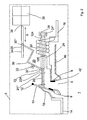
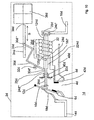
- Fig. 1 schematically a switching device 1 with a housing 2, a thermal and electromagnetic release 20 and a switching mechanism 36 is shown in the un-triggered state.
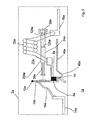
- Fig. 2 is the switching device after Fig. 1 shown in the tripped state, wherein the same or similar-acting assemblies or parts are designated by the same reference numerals.
- the contact point 4 is closed.
- a yoke 40 is still connected via an ear-shaped intermediate piece 42.
- the thermal and electromagnetic actuator 20 includes the trip coil 22 and a trip arm 24, which is here bar-shaped and arranged inside the trip coil 22 so that the coil longitudinal axis and the trip anchor longitudinal axis coincide.
- the trip arm 24 is formed of a first partial magnetic trip anchor 124 and a second partial thermal trip anchor 224 connected together at a junction 125.
- the type of connection can be positive or cohesive.
- the first partial magnetic release armature 124 is held in a trip anchor bearing 28 connected to the housing 2.
- free end 24 is the second, partial thermal release armature 224 in operative connection with a plunger 26.
- the operative connection is shown here as a positive connection, but alternatively, non-positive or cohesive connections can be realized.
- the second, partial thermal release armature 224 has a notch 25, into which engages a release lever 30 mounted in a release lever bearing 32, for example with a fork located at its first free end 30 ' End 30 "of the trigger lever 30 engages in a recess 35 in a slider 34, which is connected via a line of action 38 in operative connection with the rear derailleur 36.
- the first partial magnetic release armature 124 is made of a ferromagnetic shape memory alloy having a magnetic shape memory effect based on nickel, manganese and gallium.
- ferromagnetic shape memory alloys are known and available in principle, for example, from the Finnish company AdaptaMat Ltd. manufactured and sold.
- a typical composition of ferromagnetic shape memory alloys for use in switching devices according to the invention is given by the structural formula Ni 65-xy Mn 20 + x Ga 15 + y , where x is between 3 atomic% and 15 atomic% and y is between 3 atomic% and 12 atomic%.
- the ferromagnetic shape memory alloy used here has the property that in its martensitic phase, that is, the phase occupying the material below the thermal transition temperature, under the action of an external magnetic field on a microscopic scale, a transition between two crystal structure variants of a twin crystal structure takes place, which is macroscopic associated with a change in shape.
- the change in shape is in a linear strain in the direction of the longitudinal axis of the beam.
- the second, partial thermal release armature 224 here consists for example of a known in principle thermal shape memory alloy of nickel-titanium. With such a material, as is known, when the thermal transition temperature is exceeded, the thermal shape memory material-even without an external magnetic field-passes from its martensitic phase to its austenitic phase. This phase transition is reversible and associated with a change in shape, which also manifests itself here as a change in length of the beam-shaped second partial thermal release armature 224.
- the second partial thermal release armature 224 may also be formed of a ferromagnetic shape memory alloy of nickel, manganese, gallium differing in composition from that used in the first partial magnetic trip armature by their thermal transition temperature used ferromagnetic shape memory alloys is in the range of room temperature and is adjustable by varying the atomic percentages x and y within a bandwidth.
- the operating temperature range, within which the thermal and magnetic release operates as a purely magnetic release within a range adjustable by choice of material composition.
- the ferromagnetic shape memory material - When the thermal transition temperature is exceeded, the ferromagnetic shape memory material - even without external magnetic field - passes into its austenitic phase and behaves in this respect similar to a conventional thermal shape memory metal based on nickel and titanium.
- the ferromagnetic shape memory alloy of the first partial magnetic trip armature 124 is thus assembled to ensure effective magnetic interaction, whereas the ferromagnetic shape memory alloy of the second partial thermal trip armature 224 is selected such that the thermal transition temperature is within the desired range Consideration for the efficiency of the magnetic interaction.
- the short-circuit current tripping now happens as follows. If a high short-circuit current flows through the switching device 2 in the event of a short circuit, then the first partial magnetic release armature 124 expands due to the magnetic shape memory effect described above.
- the second thermal trip trigger armature 224 does not change in length, but is carried along by the expanding first partial magnetic trip armature 124, and as a result, the plunger 26 deflects the movable contact piece 6 away from the fixed contact 8 so that the pad 4 is opened and the switching device is triggered, as in Fig. 2 shown.
- the expansion of the ferromagnetic shape memory material happens very quickly and almost without delay.
- the delay time as the time difference between the occurrence of the short-circuit current and the maximum length of the trip armature 24 is typically on the order of one millisecond.
- the triggering is supported here by the release lever 30, which rotates in the extension of the trigger armature 24 in a clockwise direction about the trigger lever bearing 32 while the slider 34 in its longitudinal direction, indicated by the direction arrow S, shifts, so that the slide 34 on the Wirkline 38, the switching mechanism 36 is operated, which keeps the contact permanently open via active connections, not shown here.
- the current path is interrupted and the magnetic field of the tripping coil 22 breaks down again.
- the first partial magnetic release armature 124 will retract to its original dimensions, taking with it the second partial thermal release armature, which will also cause the trip lever 30 to return to the home position, as in FIG Fig. 1 shown, moved back.
- the contact point 4 is now kept permanently in the open position due to the active connections, not shown here by the switching mechanism 36.
- the thermal overcurrent tripping occurs as follows: If the current flowing in the current path through the switching device 1 exceeds its nominal value by a higher value and for a longer period than allowed, the second partial thermal release armature 224 heats up from the tripping coil 22 to one due to the heat radiation Temperature, which is above the thermal transition temperature of the thermal shape memory metal. As a result, the thermally induced shape change of the second partial thermal release armature 224 occurs, which occurs here also manifested as a longitudinal extension. The first, partial magnetic release armature 124 does not change its length because the magnetic field in the overcurrent case is insufficient.
- the release lever 30 rotates clockwise about the trigger lever bearing 32 and displaces the slider 34 in its longitudinal direction, indicated by the directional arrow S, so that the slide 34 via the line of action 38, the rear derailleur 36 is actuated, which opens the contact point via active connections, not shown here and keeps permanently open.
- the electromagnetic and the thermal tripping are thus effected by a single functional component, which is formed of two functionally different, cooperating zones.
- the construction of a switching device with a thermal and magnetic release as described is thus very simple and cheaper due to the omission of a complete assembly than conventional switching devices.
- Fig. 3 is a further embodiment of a switching device 1a according to the invention in non-tripped state, and in Fig. 4 the switching device 1a shown in a triggered state.
- Identical or equivalent components and parts are given the same reference numerals as in FIGS Fig. 1 and 2 , supplemented by the letter a.
- the essential difference between the switching device 1a according to Fig. 3 and 4 and the switching device 1 according to Fig. 1 and 2 that is, in the former, the trip armature 24a is disposed with the first partial magnetic trip armature 124a and the second partial thermal trip armature 224a external to the trip coil 22a.
- the release lever 30a, the slider 34a and the derailleur 36a in the Fig. 3 and 4 for the sake of clarity not shown.
- the switch lever 30a, the slider 34a and the derailleur 36a in the Fig. 3 and 4 for the sake of clarity not shown.
- the derailleur 36a in short-circuit current case, the
- a corresponding design of the trip coil 22a and the magnetic circuit can be made by a person skilled in the art with the aid of his normal knowledge and supported by systematic experiments.
- the heating of the second, partial thermal release armature 224 is also carried out by thermal radiation from the trip coil 22nd
- Fig. 5 is a further embodiment of a switching device 1b according to the invention in non-tripped state and in Fig. 6 the switching device 1 b shown in a triggered state.
- the same or equivalent components and parts are denoted by the same reference numerals as in the switching device 1 in the Fig. 1 and 2 , supplemented by the letter b.
- the first partial magnetic release armature 124b is formed as a sheet metal strip made of a ferromagnetic shape memory alloy.
- the second, partial thermal release armature 224b is formed as a sheet metal strip made of a thermal shape memory alloy or a - known per se - bimetallic strip.
- the two metal strips of the first, magnetic partial release armature 124b and the second partial thermal release armature 224b are connected to each other in a form, force or material fit, so that bending of the two partial release anchors bends the release armature 24b as a whole.
- the trigger anchor 24b With a first, fixed end 24b ', the trigger anchor 24b is fixedly clamped on one side to the trigger anchor bearing 28b, so that it acts as a bending beam as a whole.
- the tripping armature 24b is disposed inside the tripping coil 22b.
- the change in shape induced by the magnetic field of the tripping coil 22b in the event of a short circuit here is a bending of the first, magnetic partial tripping armature 124b, and the change in shape induced by temperature increase due to thermal radiation from the tripping coil 22b here is a deflection of the second partial thermal tripping armature 224b, respectively at the second, free end 24b ", see Fig.
- the second, free end 24b "of the release armature 24b engages in a recess 35b in a first leg 33b of the L-shaped slider 34b, whereby this upon bending of the release armature 24b in the direction of the longitudinal extension direction of the first leg 33b, indicated by the directional arrow S,
- the slide 34b is in operative connection with the plunger 26b, which, when the slide 34b is displaced, deflects the movable contact 6b away from the fixed contact 8b, thereby opening the contact point 4b of the Fig. 5 and 6 for the sake of clarity not shown.
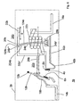
- Fig. 7 is a further embodiment of a switching device 1c according to the invention in non-tripped state and in Fig. 8 the switching device 1 c shown in a triggered state.
- the same or equivalent components and parts are denoted by the same reference numerals as in the switching device 1 in the Fig. 1 and 2 , supplemented by the letter c.
- the main difference between the switching device 1c according to Fig. 7 and 8th and the switching device 1 according to Fig. 1 and 2 is that in the former of the trigger armature 24c formed spirally and is guided inside the trigger coil 24c in a parallel to the coil axis aligned guide sleeve 23c.
- first magnetic trip striker coil 124c It is formed of a first magnetic trip striker coil 124c, and a second partial thermal trip striker coil 224c. Both partial trigger armature spirals 124c and 224c are arranged one behind the other and are connected to one another at the connection point 125c in a positive, non-positive or cohesive manner.
- the first partial release magnetic magnetic coil 124c is made of a ferromagnetic shape memory alloy having a magnetic shape memory effect based on nickel, manganese and gallium.
- the second, partial thermal release armature spiral 224c here consists, for example, of a thermal shape memory alloy of nickel-titanium, or of a thermobimetal, known in principle.
- the change in shape of the helical trigger armature 24c induced by the magnetic field of the tripping coil 22c in the event of a short circuit or by temperature increase of the tripping armature 24c due to thermal radiation from the tripping coil 22c here in the first case lies in an extension of the first, magnetic partial tripping armature coil 124c, as a result of which second partial thermal release armature coil 224c is displaced, or in the second case in an extension of the second partial thermal release armature coil 224c, and thus in each case in an integral extension of the trigger armature spiral 24c in the direction of the spiral longitudinal axis, indicated by the directional arrow L.
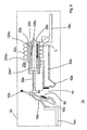
- Fig. 9 is a further embodiment of a switching device 1d according to the invention in non-tripped state
- Fig. 10 is the switching device 1d in a triggered state shown.
- the same or equivalent components and parts are denoted by the same reference numerals as in the switching device 1 in the Fig. 1 and 2 , supplemented by the letter d.
- FIG. 9 The embodiment shown differs from that in FIG Fig. 1 in that, in the former, the heating of the release armature 24d takes place directly by current flow and not, as with the latter, indirectly via thermal radiation from the release coil 22d.
- the current path in the embodiment according to Fig. 9 is as follows: from the input terminal 14d, the current flows through the movable wire 18d, the contact lever 10d. the pad 4d passes through the trip coil 22d and further in series therewith via another movable lead 18d 'which electrically connects the end of the trip coil 22d to the second partial thermal trip armature 224d through it and the first partial magnetic trip arm 124d through and from its fixed end 24d 'on to the output terminal 16d.
- the first partial thermal release armature 224d is thus directly heated by current heat.
- a thermally more accurate design of the thermal and magnetic release 20d is possible.
- a return spring 46d provided in support of the re-deformation of the release armature 24d after tripping in the short-circuit current case after breakdown of the magnetic field of the tripping coil 22d or in the event of overcurrent after cooling of the tripping armature 24d to a temperature below the thermal transition temperature due to the contact opening - Fig. 9 and 10 .
- This is designed here as a spiral spring and includes the plunger 26d. But it could also be designed as a leaf spring or in any other suitable manner.
- the return spring is in a non-triggered state ( Fig. 9 ) relaxed. It is supported at one end to a spring bearing 50d connected to the housing, and at its other end to the movable end 24d "of the trigger armature 24d. Fig. 10 ) it is compressed by the expanding trigger anchor 24d.
- FIG. 1 to 10 Illustrated and described embodiments are an exemplary, non-exhaustive representation of possible inventive switching devices using a thermal and electromagnetic release with a trigger armature of a first, magnetic partial trip anchor and a second, partial thermal tripping anchor. It can also from all others in the state Known in the art switchgear variants with thermal and electromagnetic triggers are produced by the inventive use of a ferromagnetic shape memory alloy in a first, magnetic partial tripping armature of a first, magnetic partial tripping armature and a second, partial tripping trigger trip triggered tripping armature according to the invention.
Landscapes
- Physics & Mathematics (AREA)
- Electromagnetism (AREA)
- Breakers (AREA)
- Thermally Actuated Switches (AREA)
- Electromagnets (AREA)
- Portable Nailing Machines And Staplers (AREA)
Claims (18)
- Appareil de commutation (1, 1a, 1b, 1c, 1d) avec un boîtier (2, 2a, 2b, 2c, 2d) et avec au moins un point de contact (4, 4a, 4b, 4c, 4d) comprenant un élément de contact fixe (8, 8a, 8b,8c, 8d) et un élément de contact mobile (6, 6a, 6b, 6c, 6d), et avec un déclencheur thermique et magnétique (20, 20a, 20b, 20c, 20d) qui comprend une bobine de déclenchement (22, 22a, 22b, 22c, 22d) et un induit de déclenchement (24, 24a, 24b, 24c, 24d), lequel induit de déclenchement (24, 24a, 24b, 24c, 24d) comprend au moins deux induits de déclenchement partiels en liaison active, le deuxième induit de déclenchement partiel (224, 224a, 224b, 224c, 224d) étant formé d'un bilame thermique ou d'un matériau à effet de mémoire de forme thermique ou d'un matériau à effet de mémoire de forme thermique et mécanique combinée, l'induit de déclenchement (24, 24a, 24b, 24c, 24d) étant déformé sous l'effet à la fois du champ magnétique de la bobine de déclenchement (22, 22a, 22b, 22c, 22d) en cas de courant de court-circuit et d'une élévation de la température provoquée par une surintensité pour provoquer l'ouverture du point de contact (4, 4a, 4b, 4c, 4d), caractérisé en ce que le premier induit de déclenchement partiel (124, 124a, 124b, 124c, 124d) est fait d'un premier matériau à effet de mémoire de forme magnétique.
- Appareil de commutation selon la revendication 1, caractérisé en ce que le premier induit de déclenchement partiel (124, 124a, 124b, 124c, 124d) est fait d'un alliage à mémoire de forme ferromagnétique à base de nickel, de manganèse et de gallium.
- Appareil de commutation selon la revendication 1 ou 2, caractérisé en ce que le premier induit de déclenchement partiel et le deuxième (124, 124a, 124b, 124c, 124d ; 224, 224a, 224b, 224c, 224d) sont faits d'alliages à mémoire de forme ferromagnétiques à base de nickel, de manganèse et de gallium ayant des compositions différentes.
- Appareil de commutation selon l'une des revendications 1 à 3, caractérisé en ce que le premier induit de déclenchement partiel et le deuxième (124, 124a, 124b, 124c, 124d ; 224, 224a, 224b, 224c, 224d) sont conçus comme des éléments allongés, le champ magnétique de la bobine de déclenchement (22, 22a, 22b, 22c, 22d) en en cas de courant de court-circuit provoquant l'allongement du premier induit de déclenchement partiel (124, 124a, 124b, 124c, 124d) et une élévation de la température provoquée par une surintensité provoquant l'allongement du deuxième induit de déclenchement partiel (224, 224a, 224b, 224c, 224d) dans le sens de leur axe longitudinal.
- Appareil de commutation selon l'une des revendications 1 à 3, caractérisé en ce que le premier induit de déclenchement partiel et le deuxième sont en forme de barre, l'influence du champ magnétique de la bobine de déclenchement en cas de courant de court-circuit provoquant un cintrage du premier induit de déclenchement partiel et une élévation de la température provoquée par une surintensité un cintrage du deuxième induit de déclenchement partiel.
- Appareil de commutation selon l'une des revendications 1 à 3, caractérisé en ce que les premier et deuxième induits de déclenchement partiels sont en forme de spirale, le champ magnétique de la bobine de déclenchement en cas de courant de court-circuit provoquant l'allongement du premier induit de déclenchement partiel et l'élévation de la température provoquée par une surintensité l'allongement du deuxième induit de déclenchement partiel dans le sens de l'axe longitudinal de la spirale.
- Appareil de commutation selon l'une des revendications 1 à 6, caractérisé en ce que l'induit de déclenchement est entouré par la bobine de déclenchement.
- Appareil de commutation selon l'une des revendications 1 à 6. caractérisé en ce que l'induit de déclenchement est disposé à l'extérieur et à proximité de la bobine.
- Appareil de commutation selon l'une des revendications précédentes, caractérisé en ce que l'élévation de la température de l'induit de déclenchement en cas de surintensité est obtenu par chauffage indirect par la bobine de déclenchement acheminant la surintensité.
- Appareil de commutation selon l'une des revendications 1 à 8, caractérisé en ce que l'élévation de la température de l'induit de déclenchement en cas de surintensité est obtenue par chauffage direct sous l'effet de la surintensité parcourant l'induit de déclenchement.
- Appareil de commutation selon l'une des revendications 1 à 10, caractérisé en ce que l'induit de déclenchement est retenu à une première extrémité dans un palier relié au boîtier.
- Appareil de commutation selon l'une des revendications 1 à 10, caractérisé en ce que l'induit de déclenchement est en liaison active avec un poussoir à une deuxième extrémité.
- Utilisation d'un matériau à effet de mémoire de forme magnétique dans un disjoncteur thermique et électromagnétique pour un appareil de commutation comprenant une bobine de déclenchement et un induit de déclenchement avec deux induits de déclenchement partiels en liaison active, caractérisée en ce qu'un premier induit de déclenchement partiel du disjoncteur est fait d'un matériau à effet de mémoire de forme magnétique et un deuxième induit de déclenchement partiel d'un bilame thermique ou d'un matériau à effet de mémoire de forme thermique ou d'un matériau à effet de mémoire de forme thermique et magnétique combiné, dans lequel l'induit de déclenchement est déformé et le point le point de contact ouvert aussi bien sous l'action du champ magnétique de la bobine de déclenchement en cas de courant de court-circuit que de l'élévation de la température provoquée par une surintensité.
- Utilisation d'un matériau à effet de mémoire de forme magnétique selon la revendication 13, composé d'un alliage à mémoire de forme ferromagnétique à base de nickel, de manganèse et de gallium.
- Utilisation d'un matériau à effet de mémoire de forme magnétique selon la revendication 14, caractérisée en ce que le premier induit de déclenchement partiel et le deuxième (124, 124a, 124b, 124c, 124d ; 224, 224a, 224b, 224c, 224d) sont faits d'alliages à mémoire de forme ferromagnétiques à base de nickel, de manganèse et de gallium de compositions différentes.
- Utilisation d'un matériau à effet de mémoire de forme magnétique pour le déclenchement en cas de court-circuit et de surintensité dans un appareil de commutation comprenant une bobine de déclenchement et un disjoncteur thermique et électromagnétique, caractérisée en ce qu'un premier induit de déclenchement partiel de l'induit de déclenchement comprenant deux induits de déclenchement partiels en liaison active est composé du matériau à effet de mémoire de forme magnétique et un deuxième induit de déclenchement partiel de l'induit de déclenchement comprenant deux induits de déclenchement partiels en liaison active est fait d'un bilame thermique ou d'un matériau à effet de mémoire de forme thermique ou d'un matériau à effet de mémoire de forme thermique et magnétique combiné, l'induit de déclenchement étant déformé et le point de contact ainsi ouvert aussi bien sous l'action du champ magnétique de la bobine de déclenchement en cas de courant de court-circuit que de l'élévation de la température provoquée par une surintensité.
- Utilisation d'un matériau à effet de mémoire de forme magnétique pour le déclenchement en cas de court-circuit et de surintensité selon la revendication 16, composé d'un alliage à mémoire de forme ferromagnétique à base de nickel, de manganèse et de gallium.
- Utilisation d'un matériau à effet de mémoire de forme magnétique pour le déclenchement en cas de court-circuit et de surintensité selon la revendication 17, composé d'alliages à mémoire de forme ferromagnétiques à base de nickel, de manganèse et de gallium ayant des compositions différentes pour former le premier induit de déclenchement partiel et le deuxième (124, 124a, 124b, 124c, 124d ; 224, 224a, 224b, 224c, 224d).
Applications Claiming Priority (2)
| Application Number | Priority Date | Filing Date | Title |
|---|---|---|---|
| DE102004056278A DE102004056278A1 (de) | 2004-11-22 | 2004-11-22 | Schaltgerät mit einem thermischen und elektromagnetischen Auslöser |
| PCT/EP2005/012189 WO2006056336A1 (fr) | 2004-11-22 | 2005-11-15 | Appareil de commutation comprenant un declencheur thermique et electromagnetique |
Publications (2)
| Publication Number | Publication Date |
|---|---|
| EP1815490A1 EP1815490A1 (fr) | 2007-08-08 |
| EP1815490B1 true EP1815490B1 (fr) | 2008-04-16 |
Family
ID=35590974
Family Applications (1)
| Application Number | Title | Priority Date | Filing Date |
|---|---|---|---|
| EP05807579A Not-in-force EP1815490B1 (fr) | 2004-11-22 | 2005-11-15 | Appareil de commutation comprenant un declencheur thermique et electromagnetique |
Country Status (7)
| Country | Link |
|---|---|
| US (1) | US20080117006A1 (fr) |
| EP (1) | EP1815490B1 (fr) |
| CN (1) | CN101061560A (fr) |
| AT (1) | ATE392705T1 (fr) |
| CA (1) | CA2582319A1 (fr) |
| DE (2) | DE102004056278A1 (fr) |
| WO (1) | WO2006056336A1 (fr) |
Families Citing this family (13)
| Publication number | Priority date | Publication date | Assignee | Title |
|---|---|---|---|---|
| US8830026B2 (en) | 2010-12-30 | 2014-09-09 | General Electric Company | Shape memory alloy actuated circuit breaker |
| EP2544206B1 (fr) * | 2011-07-05 | 2016-12-14 | Siemens Aktiengesellschaft | Commutateur de puissance |
| ITMI20111412A1 (it) * | 2011-07-28 | 2013-01-29 | Electrica Srl | Dispositivo a rele' a configurazione bilanciata con prestazioni migliorate |
| DE102012011063A1 (de) * | 2012-06-04 | 2013-12-05 | Fraunhofer-Gesellschaft zur Förderung der angewandten Forschung e.V. | Elektrisches Schaltgerät, insbesondere Schutzschalter |
| DE102013202795C5 (de) * | 2013-02-20 | 2019-01-24 | Phoenix Contact Gmbh & Co. Kg | Reversible Abtrennvorrichtung |
| FR3003394B1 (fr) * | 2013-03-12 | 2015-03-06 | Hager Electro Sas | Actionneur magnetothermique. |
| CN104505316B (zh) * | 2015-01-14 | 2017-04-05 | 法泰电器(江苏)股份有限公司 | 断路器的过电流保护装置 |
| WO2016176509A1 (fr) * | 2015-04-28 | 2016-11-03 | University Of Washington | Nano-actionneur en alliage à mémoire de forme ferromagnétique et son procédé d'utilisation |
| DE102016105341B4 (de) * | 2016-03-22 | 2022-05-25 | Eaton Intelligent Power Limited | Schutzschaltgerät |
| IT201700050295A1 (it) * | 2017-05-10 | 2018-11-10 | Bitron Spa | Metodo di accoppiamento di un filo con terminale elettrico e attuatore realizzato utilizzando tale metodo. |
| TWI682417B (zh) * | 2019-02-20 | 2020-01-11 | 易湘雲 | 過熱斷電的開關、用電設備及其過熱斷電的方法 |
| CN112034940B (zh) * | 2020-08-20 | 2021-07-06 | 杭州皓倡科技有限公司 | 一种用于互联网区域链技术研发的后台服务终端 |
| US20230207244A1 (en) * | 2021-12-28 | 2023-06-29 | Schneider Electric USA, Inc. | Circuit breakers |
Family Cites Families (2)
| Publication number | Priority date | Publication date | Assignee | Title |
|---|---|---|---|---|
| DE9405745U1 (de) * | 1994-03-09 | 1994-05-19 | Siemens Ag | Überstromauslöser |
| DE4413888B4 (de) * | 1994-04-21 | 2004-09-02 | Abb Patent Gmbh | Überstromauslöser für einen Selbstschalter |
-
2004
- 2004-11-22 DE DE102004056278A patent/DE102004056278A1/de not_active Withdrawn
-
2005
- 2005-11-15 DE DE502005003781T patent/DE502005003781D1/de active Active
- 2005-11-15 AT AT05807579T patent/ATE392705T1/de not_active IP Right Cessation
- 2005-11-15 WO PCT/EP2005/012189 patent/WO2006056336A1/fr active IP Right Grant
- 2005-11-15 EP EP05807579A patent/EP1815490B1/fr not_active Not-in-force
- 2005-11-15 CN CNA2005800399237A patent/CN101061560A/zh active Pending
- 2005-11-15 CA CA002582319A patent/CA2582319A1/fr not_active Abandoned
- 2005-11-15 US US11/667,835 patent/US20080117006A1/en not_active Abandoned
Also Published As
| Publication number | Publication date |
|---|---|
| EP1815490A1 (fr) | 2007-08-08 |
| DE502005003781D1 (de) | 2008-05-29 |
| CA2582319A1 (fr) | 2006-06-01 |
| US20080117006A1 (en) | 2008-05-22 |
| WO2006056336A1 (fr) | 2006-06-01 |
| CN101061560A (zh) | 2007-10-24 |
| DE102004056278A1 (de) | 2006-06-08 |
| ATE392705T1 (de) | 2008-05-15 |
Similar Documents
| Publication | Publication Date | Title |
|---|---|---|
| EP1815490B1 (fr) | Appareil de commutation comprenant un declencheur thermique et electromagnetique | |
| EP0037490B1 (fr) | Dispositif de déclenchement d'un interrupteur automatique pour interrompre un circuit | |
| EP1949399A1 (fr) | Appareil de commutation electrique a magnetostriction | |
| WO2006056337A1 (fr) | Appareil de commutation comprenant un declencheur electromagnetique | |
| WO2006056335A1 (fr) | Appareil de commutation comprenant un declencheur electromagnetique | |
| DE102004056280A1 (de) | Schaltgerät mit einem elektromagnetischen Auslöser | |
| DE102004056279A1 (de) | Schaltgerät mit einem thermischen und elektromagnetischen Auslöser | |
| DE102012013433B4 (de) | Installationsschaltgerät mit einem thermomechanischen Wandler | |
| AT405113B (de) | Auslöse-einrichtung für ein überstrom-abschaltgerät | |
| DE102008026813A1 (de) | Elektrischer selektiver Selbstschalter | |
| DE102004056283A1 (de) | Schaltgerät mit einem thermischen und elektromagnetischen Auslöser | |
| WO2017148640A1 (fr) | Dispositif de déclenchement et disjoncteur électromécanique de protection | |
| DE102012011063A1 (de) | Elektrisches Schaltgerät, insbesondere Schutzschalter | |
| DE10062704A1 (de) | Elektromechanisches Bauelement | |
| DE102004056282A1 (de) | Schaltgerät mit einem thermischen und elektromagnetischen Auslöser | |
| DE10108634C2 (de) | Elektromechanisches Bauelement | |
| DE10030394C1 (de) | Schaltereinrichtung mit einem Aktuatorelement aus einer Form-Gedächtnis-Legierung | |
| DE102004056281A1 (de) | Schaltgerät mit einem elektromagnetischen Auslöser | |
| WO1996011487A1 (fr) | Appareil de distribution electromagnetique | |
| DE102017106694A1 (de) | Aktuator mit magnetischer Formgedächtnislegierung und Installationsschaltvorrichtung mit einem derartigen Aktuator | |
| DE102005046640B4 (de) | Elektrisches Installationsgerät | |
| DE102017202790B4 (de) | Elektromechanisches Schutzschaltgerät | |
| DE10039203C2 (de) | Verwendung der Begrenzung des Bewegungsweges eines Aktors aus einer Formgedächtnis-Legierung in einem elektromechanischen Bauelement | |
| EP3879555A1 (fr) | Déclencheur à surintensité thermique à base de cnt pour commutateurs électromécaniques | |
| DE102010020245A1 (de) | Thermischer Auslöser |
Legal Events
| Date | Code | Title | Description |
|---|---|---|---|
| PUAI | Public reference made under article 153(3) epc to a published international application that has entered the european phase |
Free format text: ORIGINAL CODE: 0009012 |
|
| 17P | Request for examination filed |
Effective date: 20070125 |
|
| AK | Designated contracting states |
Kind code of ref document: A1 Designated state(s): AT BE BG CH CY CZ DE DK EE ES FI FR GB GR HU IE IS IT LI LT LU LV MC NL PL PT RO SE SI SK TR |
|
| GRAP | Despatch of communication of intention to grant a patent |
Free format text: ORIGINAL CODE: EPIDOSNIGR1 |
|
| DAX | Request for extension of the european patent (deleted) | ||
| GRAS | Grant fee paid |
Free format text: ORIGINAL CODE: EPIDOSNIGR3 |
|
| GRAA | (expected) grant |
Free format text: ORIGINAL CODE: 0009210 |
|
| RAP1 | Party data changed (applicant data changed or rights of an application transferred) |
Owner name: ABB AG |
|
| AK | Designated contracting states |
Kind code of ref document: B1 Designated state(s): AT BE BG CH CY CZ DE DK EE ES FI FR GB GR HU IE IS IT LI LT LU LV MC NL PL PT RO SE SI SK TR |
|
| REG | Reference to a national code |
Ref country code: CH Ref legal event code: EP |
|
| REG | Reference to a national code |
Ref country code: IE Ref legal event code: FG4D Free format text: LANGUAGE OF EP DOCUMENT: GERMAN |
|
| REF | Corresponds to: |
Ref document number: 502005003781 Country of ref document: DE Date of ref document: 20080529 Kind code of ref document: P |
|
| PG25 | Lapsed in a contracting state [announced via postgrant information from national office to epo] |
Ref country code: SI Free format text: LAPSE BECAUSE OF FAILURE TO SUBMIT A TRANSLATION OF THE DESCRIPTION OR TO PAY THE FEE WITHIN THE PRESCRIBED TIME-LIMIT Effective date: 20080416 |
|
| NLV1 | Nl: lapsed or annulled due to failure to fulfill the requirements of art. 29p and 29m of the patents act | ||
| PG25 | Lapsed in a contracting state [announced via postgrant information from national office to epo] |
Ref country code: ES Free format text: LAPSE BECAUSE OF FAILURE TO SUBMIT A TRANSLATION OF THE DESCRIPTION OR TO PAY THE FEE WITHIN THE PRESCRIBED TIME-LIMIT Effective date: 20080727 Ref country code: FI Free format text: LAPSE BECAUSE OF FAILURE TO SUBMIT A TRANSLATION OF THE DESCRIPTION OR TO PAY THE FEE WITHIN THE PRESCRIBED TIME-LIMIT Effective date: 20080416 Ref country code: PT Free format text: LAPSE BECAUSE OF FAILURE TO SUBMIT A TRANSLATION OF THE DESCRIPTION OR TO PAY THE FEE WITHIN THE PRESCRIBED TIME-LIMIT Effective date: 20080917 Ref country code: BG Free format text: LAPSE BECAUSE OF FAILURE TO SUBMIT A TRANSLATION OF THE DESCRIPTION OR TO PAY THE FEE WITHIN THE PRESCRIBED TIME-LIMIT Effective date: 20080716 Ref country code: NL Free format text: LAPSE BECAUSE OF FAILURE TO SUBMIT A TRANSLATION OF THE DESCRIPTION OR TO PAY THE FEE WITHIN THE PRESCRIBED TIME-LIMIT Effective date: 20080416 |
|
| PG25 | Lapsed in a contracting state [announced via postgrant information from national office to epo] |
Ref country code: LV Free format text: LAPSE BECAUSE OF FAILURE TO SUBMIT A TRANSLATION OF THE DESCRIPTION OR TO PAY THE FEE WITHIN THE PRESCRIBED TIME-LIMIT Effective date: 20080416 Ref country code: PL Free format text: LAPSE BECAUSE OF FAILURE TO SUBMIT A TRANSLATION OF THE DESCRIPTION OR TO PAY THE FEE WITHIN THE PRESCRIBED TIME-LIMIT Effective date: 20080416 |
|
| REG | Reference to a national code |
Ref country code: IE Ref legal event code: FD4D |
|
| PG25 | Lapsed in a contracting state [announced via postgrant information from national office to epo] |
Ref country code: IS Free format text: LAPSE BECAUSE OF FAILURE TO SUBMIT A TRANSLATION OF THE DESCRIPTION OR TO PAY THE FEE WITHIN THE PRESCRIBED TIME-LIMIT Effective date: 20080816 |
|
| PG25 | Lapsed in a contracting state [announced via postgrant information from national office to epo] |
Ref country code: SE Free format text: LAPSE BECAUSE OF FAILURE TO SUBMIT A TRANSLATION OF THE DESCRIPTION OR TO PAY THE FEE WITHIN THE PRESCRIBED TIME-LIMIT Effective date: 20080716 Ref country code: IE Free format text: LAPSE BECAUSE OF FAILURE TO SUBMIT A TRANSLATION OF THE DESCRIPTION OR TO PAY THE FEE WITHIN THE PRESCRIBED TIME-LIMIT Effective date: 20080416 Ref country code: DK Free format text: LAPSE BECAUSE OF FAILURE TO SUBMIT A TRANSLATION OF THE DESCRIPTION OR TO PAY THE FEE WITHIN THE PRESCRIBED TIME-LIMIT Effective date: 20080416 Ref country code: CZ Free format text: LAPSE BECAUSE OF FAILURE TO SUBMIT A TRANSLATION OF THE DESCRIPTION OR TO PAY THE FEE WITHIN THE PRESCRIBED TIME-LIMIT Effective date: 20080416 Ref country code: LT Free format text: LAPSE BECAUSE OF FAILURE TO SUBMIT A TRANSLATION OF THE DESCRIPTION OR TO PAY THE FEE WITHIN THE PRESCRIBED TIME-LIMIT Effective date: 20080416 |
|
| PLBE | No opposition filed within time limit |
Free format text: ORIGINAL CODE: 0009261 |
|
| STAA | Information on the status of an ep patent application or granted ep patent |
Free format text: STATUS: NO OPPOSITION FILED WITHIN TIME LIMIT |
|
| EN | Fr: translation not filed | ||
| PG25 | Lapsed in a contracting state [announced via postgrant information from national office to epo] |
Ref country code: SK Free format text: LAPSE BECAUSE OF FAILURE TO SUBMIT A TRANSLATION OF THE DESCRIPTION OR TO PAY THE FEE WITHIN THE PRESCRIBED TIME-LIMIT Effective date: 20080416 Ref country code: RO Free format text: LAPSE BECAUSE OF FAILURE TO SUBMIT A TRANSLATION OF THE DESCRIPTION OR TO PAY THE FEE WITHIN THE PRESCRIBED TIME-LIMIT Effective date: 20080416 |
|
| 26N | No opposition filed |
Effective date: 20090119 |
|
| PG25 | Lapsed in a contracting state [announced via postgrant information from national office to epo] |
Ref country code: EE Free format text: LAPSE BECAUSE OF FAILURE TO SUBMIT A TRANSLATION OF THE DESCRIPTION OR TO PAY THE FEE WITHIN THE PRESCRIBED TIME-LIMIT Effective date: 20080416 |
|
| BERE | Be: lapsed |
Owner name: ABB A.G. Effective date: 20081130 |
|
| PG25 | Lapsed in a contracting state [announced via postgrant information from national office to epo] |
Ref country code: MC Free format text: LAPSE BECAUSE OF NON-PAYMENT OF DUE FEES Effective date: 20081130 |
|
| PG25 | Lapsed in a contracting state [announced via postgrant information from national office to epo] |
Ref country code: IT Free format text: LAPSE BECAUSE OF FAILURE TO SUBMIT A TRANSLATION OF THE DESCRIPTION OR TO PAY THE FEE WITHIN THE PRESCRIBED TIME-LIMIT Effective date: 20080416 |
|
| PG25 | Lapsed in a contracting state [announced via postgrant information from national office to epo] |
Ref country code: BE Free format text: LAPSE BECAUSE OF NON-PAYMENT OF DUE FEES Effective date: 20081130 |
|
| PG25 | Lapsed in a contracting state [announced via postgrant information from national office to epo] |
Ref country code: AT Free format text: LAPSE BECAUSE OF NON-PAYMENT OF DUE FEES Effective date: 20081115 |
|
| REG | Reference to a national code |
Ref country code: CH Ref legal event code: PL |
|
| GBPC | Gb: european patent ceased through non-payment of renewal fee |
Effective date: 20091115 |
|
| PG25 | Lapsed in a contracting state [announced via postgrant information from national office to epo] |
Ref country code: HU Free format text: LAPSE BECAUSE OF FAILURE TO SUBMIT A TRANSLATION OF THE DESCRIPTION OR TO PAY THE FEE WITHIN THE PRESCRIBED TIME-LIMIT Effective date: 20081017 Ref country code: CY Free format text: LAPSE BECAUSE OF FAILURE TO SUBMIT A TRANSLATION OF THE DESCRIPTION OR TO PAY THE FEE WITHIN THE PRESCRIBED TIME-LIMIT Effective date: 20080416 Ref country code: LU Free format text: LAPSE BECAUSE OF NON-PAYMENT OF DUE FEES Effective date: 20081115 |
|
| PG25 | Lapsed in a contracting state [announced via postgrant information from national office to epo] |
Ref country code: TR Free format text: LAPSE BECAUSE OF FAILURE TO SUBMIT A TRANSLATION OF THE DESCRIPTION OR TO PAY THE FEE WITHIN THE PRESCRIBED TIME-LIMIT Effective date: 20080416 |
|
| PG25 | Lapsed in a contracting state [announced via postgrant information from national office to epo] |
Ref country code: LI Free format text: LAPSE BECAUSE OF NON-PAYMENT OF DUE FEES Effective date: 20091130 Ref country code: CH Free format text: LAPSE BECAUSE OF NON-PAYMENT OF DUE FEES Effective date: 20091130 Ref country code: GR Free format text: LAPSE BECAUSE OF FAILURE TO SUBMIT A TRANSLATION OF THE DESCRIPTION OR TO PAY THE FEE WITHIN THE PRESCRIBED TIME-LIMIT Effective date: 20080717 |
|
| PG25 | Lapsed in a contracting state [announced via postgrant information from national office to epo] |
Ref country code: GB Free format text: LAPSE BECAUSE OF NON-PAYMENT OF DUE FEES Effective date: 20091115 |
|
| PGFP | Annual fee paid to national office [announced via postgrant information from national office to epo] |
Ref country code: DE Payment date: 20101119 Year of fee payment: 6 |
|
| PG25 | Lapsed in a contracting state [announced via postgrant information from national office to epo] |
Ref country code: FR Free format text: LAPSE BECAUSE OF FAILURE TO SUBMIT A TRANSLATION OF THE DESCRIPTION OR TO PAY THE FEE WITHIN THE PRESCRIBED TIME-LIMIT Effective date: 20090227 |
|
| REG | Reference to a national code |
Ref country code: DE Ref legal event code: R119 Ref document number: 502005003781 Country of ref document: DE Effective date: 20130601 |
|
| PG25 | Lapsed in a contracting state [announced via postgrant information from national office to epo] |
Ref country code: DE Free format text: LAPSE BECAUSE OF NON-PAYMENT OF DUE FEES Effective date: 20130601 |