EP1813753B1 - Dachfenster, insbesondere Wohndachfenster - Google Patents
Dachfenster, insbesondere Wohndachfenster Download PDFInfo
- Publication number
- EP1813753B1 EP1813753B1 EP06001903A EP06001903A EP1813753B1 EP 1813753 B1 EP1813753 B1 EP 1813753B1 EP 06001903 A EP06001903 A EP 06001903A EP 06001903 A EP06001903 A EP 06001903A EP 1813753 B1 EP1813753 B1 EP 1813753B1
- Authority
- EP
- European Patent Office
- Prior art keywords
- casement
- frame
- window frame
- sash
- auxiliary lever
- Prior art date
- Legal status (The legal status is an assumption and is not a legal conclusion. Google has not performed a legal analysis and makes no representation as to the accuracy of the status listed.)
- Expired - Lifetime
Links
Images




Classifications
-
- E—FIXED CONSTRUCTIONS
- E04—BUILDING
- E04D—ROOF COVERINGS; SKY-LIGHTS; GUTTERS; ROOF-WORKING TOOLS
- E04D13/00—Special arrangements or devices in connection with roof coverings; Protection against birds; Roof drainage ; Sky-lights
- E04D13/03—Sky-lights; Domes; Ventilating sky-lights
- E04D13/035—Sky-lights; Domes; Ventilating sky-lights characterised by having movable parts
- E04D13/0357—Sky-lights; Domes; Ventilating sky-lights characterised by having movable parts the parts pivoting about an axis supported on a hinged frame or arms
-
- E—FIXED CONSTRUCTIONS
- E04—BUILDING
- E04D—ROOF COVERINGS; SKY-LIGHTS; GUTTERS; ROOF-WORKING TOOLS
- E04D13/00—Special arrangements or devices in connection with roof coverings; Protection against birds; Roof drainage ; Sky-lights
- E04D13/03—Sky-lights; Domes; Ventilating sky-lights
- E04D13/035—Sky-lights; Domes; Ventilating sky-lights characterised by having movable parts
- E04D13/0358—Sky-lights; Domes; Ventilating sky-lights characterised by having movable parts the parts moving, in their own plane, e.g. rolling or sliding, or moving in parallel planes with or without an additional movement, e.g. both pivoting and rolling or sliding
-
- E—FIXED CONSTRUCTIONS
- E05—LOCKS; KEYS; WINDOW OR DOOR FITTINGS; SAFES
- E05F—DEVICES FOR MOVING WINGS INTO OPEN OR CLOSED POSITION; CHECKS FOR WINGS; WING FITTINGS NOT OTHERWISE PROVIDED FOR, CONCERNED WITH THE FUNCTIONING OF THE WING
- E05F1/00—Closers or openers for wings, not otherwise provided for in this subclass
- E05F1/08—Closers or openers for wings, not otherwise provided for in this subclass spring-actuated, e.g. for horizontally sliding wings
- E05F1/10—Closers or openers for wings, not otherwise provided for in this subclass spring-actuated, e.g. for horizontally sliding wings for swinging wings, e.g. counterbalance
- E05F1/1091—Closers or openers for wings, not otherwise provided for in this subclass spring-actuated, e.g. for horizontally sliding wings for swinging wings, e.g. counterbalance with a gas spring
-
- E—FIXED CONSTRUCTIONS
- E05—LOCKS; KEYS; WINDOW OR DOOR FITTINGS; SAFES
- E05D—HINGES OR SUSPENSION DEVICES FOR DOORS, WINDOWS OR WINGS
- E05D15/00—Suspension arrangements for wings
- E05D15/40—Suspension arrangements for wings supported on arms movable in vertical planes
- E05D15/44—Suspension arrangements for wings supported on arms movable in vertical planes with pivoted arms and vertically-sliding guides
-
- E—FIXED CONSTRUCTIONS
- E05—LOCKS; KEYS; WINDOW OR DOOR FITTINGS; SAFES
- E05Y—INDEXING SCHEME ASSOCIATED WITH SUBCLASSES E05D AND E05F, RELATING TO CONSTRUCTION ELEMENTS, ELECTRIC CONTROL, POWER SUPPLY, POWER SIGNAL OR TRANSMISSION, USER INTERFACES, MOUNTING OR COUPLING, DETAILS, ACCESSORIES, AUXILIARY OPERATIONS NOT OTHERWISE PROVIDED FOR, APPLICATION THEREOF
- E05Y2800/00—Details, accessories and auxiliary operations not otherwise provided for
- E05Y2800/74—Specific positions
- E05Y2800/742—Specific positions abnormal
- E05Y2800/744—Specific positions abnormal cleaning or service
-
- E—FIXED CONSTRUCTIONS
- E05—LOCKS; KEYS; WINDOW OR DOOR FITTINGS; SAFES
- E05Y—INDEXING SCHEME ASSOCIATED WITH SUBCLASSES E05D AND E05F, RELATING TO CONSTRUCTION ELEMENTS, ELECTRIC CONTROL, POWER SUPPLY, POWER SIGNAL OR TRANSMISSION, USER INTERFACES, MOUNTING OR COUPLING, DETAILS, ACCESSORIES, AUXILIARY OPERATIONS NOT OTHERWISE PROVIDED FOR, APPLICATION THEREOF
- E05Y2900/00—Application of doors, windows, wings or fittings thereof
- E05Y2900/10—Application of doors, windows, wings or fittings thereof for buildings or parts thereof
- E05Y2900/13—Type of wing
- E05Y2900/148—Windows
- E05Y2900/152—Roof windows
Definitions
- the invention relates to a roof window, in particular roof windows, with a side rails having frame and with a top cross member having wing frame having a Drehgleit Entry in the region of its upper transverse spar whose Gleit Equipmentsbahn extends over at least one of the side rails or at least a portion of the side member of the frame
- An auxiliary lever is assigned to at least one side rail, wherein the auxiliary lever at a fixed distance from each other has an attacking on the frame, relative to the frame fixed frame pivot bearing and an attacking on the casement, relative to the wing frame fixed wing frame pivot bearing.
- the invention has for its object to provide a simple and reliable roof window, which is easy to use and maintain and ensure a high density and require only low operating forces.
- a folding position can be brought, which is convertible into a rotational position of the wing of the roof window, in which the outer side of the sash facing the outside of the window frame or substantially facing ,
- a further folding function also called tilting function
- the rotational position of the wing can be realized.
- the structural complexity is this very low, since in addition to the rotation slide only the auxiliary lever is to be realized, with rotary slide and auxiliary lever can be created as standard components easily and inexpensively.
- the folding opening of the residential roof window according to the invention represents a ventilation position, which is intensified due to the transfer into the rotational position of the wing.
- the end position of the rotary position of the window sash takes a position whose main benefit allows easy cleaning of the outer pane from the room.
- the flap of the wing of the roof window according to the invention takes place about an axis of rotation which lies in the region of the upper transverse spar of the casement or of the upper transverse spar of the frame. If the wing is moved into the rotational position, the rotary sliding guide ensures that the upper transverse spar of the sash can slide or roll along at least one sliding guideway guided on at least one of the side rails.
- the auxiliary lever holds the window sash at least one side, preferably in the central region, which is approximately between the second to fourth fifth of the height of a five-fifths high wing.
- the plane of the sash or the wing assumes a 90 ° position to the plane of the frame.
- the upper cross member of the sash is - in the course of the further opening movement - moved further down on the side rail or the side rails of the frame, so that the outer side of the sash faces the outside of the window frame. If in the course of this application of upper cross member, outside, etc. is spoken, so this is based on the closed position of the roof window, in particular roof window.
- the frame pivot bearing is at least at the same height or above the axis of rotation of the rotary slide.
- the term “at the same height” or “above” refers to the installation position of the roof window, ie in an oblique position on the roof, wherein the information "at the same height” or “above” in the vertical direction and / or in the longitudinal direction of the side rails of the window frame you can see.
- the rotational sliding guide of the sash lies on the same height of the below the frame pivot bearing. The above applies regardless of the sash position of the roof window.
- the casement pivot bearing is located below the axis of rotation of the rotary slide. This is based on the mounting position on the roof, so the inclination of the roof window and based on the closed position of the wing.
- the sliding guideway extends so far that in an end position the outside of the sash is facing or facing the outside of the frame. In this end position is in particular a cleaning position, that is, the outer pane can be cleaned from the room.
- the casement frame has a circumferential or substantially circumferential overhang relative to the frame.
- This supernatant is also referred to as a rollover.
- the invention relates to a roof window, which allows folding and turning of the wing, the wing can be rotated in particular for cleaning so far that the outer pane is accessible, although a circumferential or substantially circumferential projection of the sash to the frame is present.
- a very good airtightness is achieved in the closed position.
- low opening and closing forces can be realized, since occurring friction in moving the wing due to a present Matterstanddichtsystems (also called impact seal system) is minimal.
- the orbiting respectively substantially circumferential overhang ensures a high dimensional stability, the aforementioned impact seal is improved compared to lip or sliding seals.
- the article of the invention does not cause a relative abrasion movement in the sealing area due to the impact seal.
- the invention also provides an improvement in terms of aging and resilience of the seals.
- the mentioned flashover also creates optical tightness. Even without seals no or only a minimal incidence of light through the gap between glare and sash. Due to the procedure according to the invention, an additional frame or additional profiles used today in comparable products, which / which either clipped or screwed forms a projection and thus a stop surface for a seal or the like, is eliminated.
- the auxiliary lever an opening spring, opening gas spring and / or a motion damper be assigned.
- Such an element is connected to the auxiliary lever on the one hand and with the frame on the other.
- each side member has a sliding guide track and each upper transverse member end is assigned a guide element for the sliding guide track.
- the guide elements are preferably designed as pins, which are guided in Gleit Equipmentsbahnen forming slide grooves of the side rails. A rotation is possible around the pins. Furthermore, in addition, a sliding or rolling, so a linear movement, take place.
- each side member is assigned an auxiliary lever.
- the wing is guided on both sides.
- each auxiliary lever is associated with an opening spring, opening gas spring and / or a motion damper.
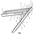
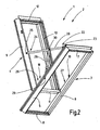
- the FIG. 1 shows a designed as a rooftop window 1 skylight 2, which has a frame 3 and a sash 4.
- the frame 3 occupies a sloping position relative to the horizontal or vertical, as it corresponds for example to a roof pitch of a pitched roof.
- the frame 3 has according to the FIGS. 1 and 2 two mutually parallel side rails 5 and 6 and an upper cross member 7 and a lower cross member 8, wherein the upper cross member 7 and lower cross member 8 are parallel to each other and each extend at a 90 ° angle to the side rails 5 and 6.
- the sash 4 has according to the Figures 2 and 3
- the upper transverse spar 11 and the lower transverse spar 12 extend parallel to one another and project at 90 ° angles to the side members 9 and 10, respectively.
- Each side rail 5, 6 and 9, 10 is an auxiliary lever 20, 21 assigned.
- auxiliary lever 20 is also - as in the FIGS. 1 and 2 shown - possible that only one auxiliary lever 20 is provided, that is, the sash 4 is guided on the frame 3 only on one side of the roof window 2 by means of an auxiliary lever.
- auxiliary lever 20 is always assumed by two auxiliary levers 20, 21, but for the sake of simplicity, only the auxiliary lever 20 will be described. The execution with respect to the auxiliary lever 21 is then corresponding.
- the auxiliary lever 20 is formed as an integral, constant length in the lever. He has at its one end 22 a frame pivot bearing 23 and in the region of its other end 24 a sash 25 pivot bearing. Blend frame pivot bearing 23 and sash pivot bearings 25 are arranged stationary with respect to the position of the frame 3 or sash 4 and have a fixed distance from each other. This distance is constant and essentially determined by the length of the auxiliary lever 20.
- the frame pivot bearing 23 By means of the frame pivot bearing 23 is the one end 22 of the auxiliary lever 20 with the frame 3, in particular with the associated side member 5, connected; by means of the casement pivot 25, the other end 24 of the auxiliary lever 20 is connected to the casement 4, in particular to its side rail 9. Both compounds are designed as rotary joints.
- the Gleit Equipmentsbahnen located in the side rails 5 and 6 18 and 19 have guide grooves 26 and 27, wherein the guide grooves 26 and 27 along the longitudinal extension of the side rails 5 and 6 extend. This course takes place in particular over a portion of the length of the side rails 5 and 6 or over the entire length of the respective side rails 5 and 6. In the guide grooves 26 and 27 engage the pins formed as guide elements 16 and 17, whereby the casement 4 opposite the frame 3 can be both pivoted and guided linearly.
- an opening gas spring 28 By means of an opening gas spring 28, the opening movement of the sash 4 is supported.
- the opening gas spring 28 engages with a End 29 on the side rail 5 of the frame 3 in the upper half and is connected to the other end 30 with the auxiliary lever 20. Both compounds of the opening gas spring 28 to the frame 3 or sash 4 are rotatably formed.
- the opening gas spring 28 is formed as a telescopic gas spring, which generates an opening pressure.
- the connection of the opening gas spring 28 with the auxiliary lever 20 is approximately in the central region of the auxiliary lever 20, preferably in the upper third.
- a tension spring and / or a torsion spring can be used.
- the opening gas spring 28 is not to be understood as a guide means, but merely serves as a display aid for the folding opening movement of the sash 4.
- sash 4 in the closed position resting on the frame 3 sash 4 has a projection 31, which is also referred to as a rollover.
- This is a section of the side rails 9 and 10 and the lower cross member 12 and optionally the upper cross member 11 of the sash 4, which engages over the frame 3.
- a projection 31 which is also referred to as a rollover.
- This is a section of the side rails 9 and 10 and the lower cross member 12 and optionally the upper cross member 11 of the sash 4, which engages over the frame 3.
- the respective spar of the sash 4 provided with a stepped recess 32 into which engages a corner portion 33 of the respective spar of the frame 3 in the closed position of the roof window 2.
- the so formed protrusion 31 is formed as a circumferential or substantially circumferential projection 31, that is, it is located on all spars or almost all spars or in some areas on the spars or almost all spars of the sash 4.
- the sash 4 In the closed position emerges accordingly - according to FIG. 11 -
- the sash 4 quasi a little way into the frame 3 a. From this it is also clear that with a substantially circumferential overhang 31 no rotation of the sash 4 is possible such that a portion of the sash 4 passes through the opening of the frame 3, as this is prevented due to the supernatant 31.
- the opening operation of the sash 4 or wing relative to the frame 3 is such that for tilting first pivoting of the sash 4 about a rotation axis in the region of the upper cross member 11 takes place and that then - in the course of a further opening movement - the sash 3 with its upper transverse spar 11th or the rotating sliding guide 13 acting there is moved along the sliding guide tracks 18 and 19, wherein in the course of further movement of the entire casement 4 rotates such that - FIG. 12 -
- the outer side 34 of the sash 4 of the outer side 35 of the window frame 3 is facing. Accordingly, from the interior of a room to which the roof window 2 is assigned, the outer pane 36 (FIG. FIG. 10 ) are cleaned.
- the arrow 37 in FIG. 12 indicates how in the course of the opening movement of the upper cross member 11 moves from top to bottom on the side rails 5 and 6 of the frame 3 and the arrow 38 of FIG. 12 indicates how at the same time the lower cross member 12 of the sash 4 moves upward.
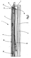
- FIG. 3 the closed position of the residential roof window 1 is shown. Accordingly, an arrangement according to FIG. 11 in front. It can be seen that the auxiliary lever 20 extends parallel to the casement 4 or frame 3 in the region of the side rails 5, 6 and 9, 10. The opening gas spring 28 assumes a slightly inclined position relative to the auxiliary lever 20.
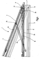
- the dormer window 1 a piece of hinged open so pivots the sash 4 about the axis of rotation 39 of the Drehgleit Unit 13, that is, formed as a pin guide members 16 and 17 rotate in the Gleit Resultssbahnen 18 and 19 forming guide grooves 26 and 27. Simultaneously pivoted the auxiliary lever 20 in the frame pivot bearing 23, but it continues to extend parallel to the sash 4.
- FIG. 8 the opening process is still more advanced, that is, the sash 4 begins to rotate so far opposite the frame 4, that the outer side 34 of the sash 4 begins to orient in the direction of the outer side 35 of the frame 3.
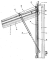
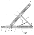
- FIG. 9 the end position of the rotational movement of the sash 4, in which the guide elements 16 and 17 have moved even further in the direction of the lower cross member 8 of the frame 3 and the first in the course of the opening movement ever further increasing angle ⁇ ( FIG. 8 ) has now reduced again between the auxiliary lever 20 and frame 3.
- a closing of the sash 4 from the out of the FIG. 9 resulting position is carried out accordingly in the reverse manner as described above for the opening operation.
Landscapes
- Engineering & Computer Science (AREA)
- Architecture (AREA)
- Civil Engineering (AREA)
- Structural Engineering (AREA)
- Wing Frames And Configurations (AREA)
- Body Structure For Vehicles (AREA)
- Vehicle Interior And Exterior Ornaments, Soundproofing, And Insulation (AREA)
- Glass Compositions (AREA)
- Window Of Vehicle (AREA)
- Compositions Of Macromolecular Compounds (AREA)
Description
- Die Erfindung betrifft ein Dachfenster, insbesondere Wohndachfenster, mit einem Seitenholme aufweisenden Blendrahmen und mit einem ein Oberquerholm aufweisenden Flügelrahmen, der im Bereich seines Oberquerholms eine Drehgleitführung aufweist, deren Gleitführungsbahn sich über mindestens einen der Seitenholme oder zumindest einen Abschnitt des Seitenholms des Blendrahmens erstreckt, wobei mindestens einem Seitenholm ein Hilfshebel zugeordnet ist, wobei der Hilfshebel in festem Abstand zueinander ein am Blendrahmen angreifendes, relativ zum Blendrahmen ortsfestes Blendrahmen-Drehlager und ein am Flügelrahmen angreifendes, relativ zum Flügelrahmen ortsfestes Flügelrahmen-Drehlager aufweist.
- Aus der
europäischen Patentanmeldung EP 0 671 522 A1 ist ein Dachfenster der eingangs genannten Art bekannt, bei dem ein Flügelrahmen mit einem Blendrahmen über eine Drehgleitführung sowie über einen Hilfshebel, der sich zwischen dem Blendrahmen und dem Flügelrahmen erstreckt und eine festgelegte Länge aufweist, in Verbindung steht. Die Drehachse der Drehgleitführung ist dabei beabstandet zu dem oberen Ende des Flügelrahmens angeordnet. Ein diese Merkmale ebenfalls aufweisendes Dachfenster geht aus derEP 0 872 610 A2 hervor. - Der Erfindung liegt die Aufgabe zugrunde, ein einfaches und funktionssicheres Dachfenster zu schaffen, das leicht bedienbar und pflegbar ist und eine hohe Dichtigkeit gewährleisten sowie nur geringe Bedienkräfte erfordern soll.
- Diese Aufgabe wird erfindungsgemäß dadurch gelöst, dass sich die Drehachse der Drehgleitführung im oberen Bereich des Oberquerholms des Flügelrahmens befindet, sodass ein Drehen des Flügelrahmens außerhalb oder im Wesentlichen außerhalb des Blendrahmens erfolgt. Gegenüber bekannten Dachfenstern, bei denen der Flügelrahmen durch den Blendrahmen hindurchschwingt, ist beim Gegenstand der Erfindung vorgesehen, dass das Drehen des Flügelrahmens außerhalb des Blendrahmens erfolgt. Demzufolge wird der Flügelrahmen nur über die Drehgleitführung und den Hilfshebel am Blendrahmen derart gehalten, dass eine Klappstellung herbeigeführt werden kann, die überführbar ist in eine Drehstellung des Flügels des Dachfensters, bei der die Außenseite des Flügelrahmens der Außenseite des Blendrahmens zugekehrt oder im Wesentlichen zugekehrt ist. Demzufolge liegt beim Gegenstand der Erfindung eine weitergehende Klappfunktion (auch Kippfunktion genannt) vor, da aus der Klappposition die Drehposition des Flügels realisiert werden kann. Der bauliche Aufwand ist hierfür sehr gering, da neben der Drehgleitführung nur der Hilfshebel zu realisieren ist, wobei Drehgleitführung und Hilfshebel als Standardbauteile einfach und kostengünstig erstellt werden können. Die Klappöffnung des erfindungsgemäßen Wohndachfensters stellt eine Lüftungsstellung dar, die aufgrund der Überführung in die Drehstellung des Flügels noch intensiviert wird. In der Endstellung der Drehstellung nimmt der Fensterflügel eine Position ein, deren Hauptnutzen ein einfaches Putzen der Außenscheibe vom Raum her ermöglicht. Demzufolge liegt eine Putzstellung vor. Das Klappen des Flügels des erfindungsgemäßen Dachfensters erfolgt um eine Drehachse, die im Bereich des Oberquerholms des Flügelrahmens beziehungsweise des oberen Querholms des Blendrahmens liegt. Wird der Flügel in die Drehposition verbracht, so sorgt die Drehgleitführung dafür, dass der Oberquerholm des Flügelrahmens entlang mindestens einer Gleitführungsbahn auf mindestens einem der Seitenholme geführt gleiten oder rollen kann. Der Hilfshebel hält dabei den Fensterflügel an mindestens einer Seite, vorzugsweise im mittleren Bereich, der in etwa zwischen dem zweiten bis vierten Fünftel der Höhe eines fünf Fünftel Einheiten hohen Flügels liegt. In einer Zwischenstellung nimmt die Ebene des Flügelrahmens beziehungsweise des Flügels eine 90°-Stellung zur Ebene des Blendrahmens ein. Der Oberquerholm des Flügelrahmens wird - im Zuge der weiteren Öffnungsbewegung - weiter nach unten auf dem Seitenholm oder den Seitenholmen des Blendrahmens verfahren, sodass sich die Außenseite des Flügelrahmens der Außenseite des Blendrahmens zukehrt. Wenn im Zuge dieser Anmeldung von Oberquerholm, Außenseite usw. gesprochen wird, so ist dies bezogen auf die geschlossene Stellung des Dachfensters, insbesondere Wohndachfensters.
- Vorzugsweise ist vorgesehen, dass das Blendrahmen-Drehlager zumindest auf gleicher Höhe oder oberhalb der Drehachse der Drehgleitführung liegt. Der Begriff "auf gleicher Höhe" beziehungsweise "oberhalb" bezieht sich auf die Einbaulage des Dachfensters, also in schräger Position am Dach, wobei die Angaben "auf gleicher Höhe" oder "oberhalb" in vertikaler Richtung und/oder in Längserstreckungsrichtung der Seitenholme des Blendrahmens zu sehen sind. Demzufolge liegt die Drehgleitführung des Flügelrahmens auf gleicher Höhe der unterhalb des Blendrahmen-Drehlagers. Vorstehendes gilt unabhängig von der Flügelstellung des Dachfensters.
- Nach einer Weiterbildung der Erfindung ist vorgesehen, dass das Flügelrahmen-Drehlager unterhalb der Drehachse der Drehgleitführung liegt. Dies ist bezogen auf die Einbaulage am Dach, also die Schräglage des Dachfensters und bezogen auf die geschlossene Stellung des Flügels.
- Nach einer Weiterbildung der Erfindung ist vorgesehen, dass sich die Gleitführungsbahn derart weit erstreckt, dass in einer Endstellung die Außenseite des Flügelrahmens der Außenseite des Blendrahmens zugekehrt oder in etwa zugekehrt ist. In dieser Endstellung liegt insbesondere eine Putzstellung vor, das heißt, die Außenscheibe lässt sich vom Raum aus putzen.
- Es ist vorteilhaft, wenn der Flügelrahmen gegenüber dem Blendrahmen einen umlaufenden oder im Wesentlichen umlaufenden Überstand aufweist. Dieser Überstand wird auch als Überschlag bezeichnet. Demzufolge betrifft die Erfindung ein Dachfenster, das ein Klappen und ein Drehen des Flügels erlaubt, wobei der Flügel insbesondere zum Putzen so weit gedreht werden kann, dass die Außenscheibe zugänglich ist, obwohl ein umlaufender oder im Wesentlichen umlaufender Überstand des Flügelrahmens zum Blendrahmen vorhanden ist. Durch den Überstand wird in der Schließstellung eine sehr gute Luftdichtigkeit erzielt. Ferner können niedrige Öffnungsund Schließkräfte realisiert werden, da auftretende Reibungen beim Bewegen des Flügels aufgrund eines vorliegenden Überstanddichtsystems (auch Aufschlagdichtsystem genannt) minimal ist. Des weiteren ist durch den umlaufenden beziehungsweise im Wesentlichen umlaufenden Überstand eine hohe Formstabilität gewährleistet, wobei die bereits erwähnte Aufschlagdichtung im Vergleich zu Lippenbeziehungsweise Schleifdichtungen verbessert ist. Im Unterschied zu den Schleifdichtungen findet beim Gegenstand der Erfindung aufgrund der Aufschlagdichtung keine relative Abriebbewegung im Dichtungsbereich statt. Bei der Erfindung ist auch eine Verbesserung im Hinblick auf Alterung und Rückstellvermögen der Dichtungen gegeben. Der erwähnte Überschlag schafft ferner optische Dichtheit. Selbst ohne Dichtungen erfolgt kein oder nur ein minimaler Lichteinfall durch den Spalt zwischen Blend- und Flügelrahmen. Aufgrund des erfindungsgemäßen Vorgehens entfällt ein heute bei vergleichbaren Produkten eingesetzter Zusatzrahmen oder Zusatzprofile, welcher/welche entweder geklipst oder geschraubt einen Überstand und damit eine Anschlagsfläche für eine Dichtung oder dergleichen bildet/bilden. Es entfällt auch ein Wegfräsen des Überstandes bei bekannten Fenstern im Bereich, in welchem der Flügelrahmen in den Blendrahmen einschwingt. Ferner ist eine hohe Sicherheit gegen Durchbiegen des Flügelrahmens, beispielsweise aufgrund von Materialalterung, Materialermüdung usw., sowie bei Druckbeanspruchung (zum Beispiel durch Winddruck, Schneelast usw.) von außen gegeben.
- Bevorzugt kann dem Hilfshebel eine Öffnungsfeder, Öffnungsgasfeder und/oder ein Bewegungsdämpfer zugeordnet sein. Ein derartiges Element ist mit dem Hilfshebel einerseits und mit dem Blendrahmen andererseits verbunden.
- Eine Weiterbildung der Erfindung sieht vor, dass jedem Seitenholm eine Gleitführungsbahn und jedem Oberquerholmende ein Führungselement für die Gleitführungsbahn zugeordnet ist. Demzufolge ist der Flügel auf beiden Seiten geführt. Die Führungselemente sind vorzugsweise als Zapfen ausgebildet, die in Gleitführungsbahnen bildenden Gleitnuten der Seitenholme geführt sind. Um die Zapfen ist eine Drehbewegung möglich. Ferner kann zusätzlich ein Gleiten oder Rollen, also eine Linearbewegung, erfolgen.
- Es ist vorteilhaft, wenn jedem Seitenholm ein Hilfshebel zugeordnet ist. Damit wird der Flügel beidseitig geführt.
- Schließlich ist vorgesehen, dass jedem Hilfshebel eine Öffnungsfeder, Öffnungsgasfeder und/oder ein Bewegungsdämpfer zugeordnet ist.
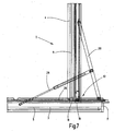
- Die Zeichnungen veranschaulichen die Erfindung anhand eines Ausführungsbeispiels, und zwar zeigt:
- Figur 1
- eine perspektivische Ansicht auf ein als Wohndachfenster ausgebildetes Dachfenster in Klappöffnungsstellung,
- Figur 2
- das Dachfenster der
Figur 1 in Drehendstellung (Putzstellung), - Figur 3
- eine Seitenansicht auf ein horizontal liegendes Dachfenster entsprechend der Ausbildung nach
Figur 1 in Schließstellung (Ausschnittsdarstellung), - Figur 4
- das Dachfenster der
Figur 3 in Anfangsöffnungsstellung (Teilklappstellung), - Figur 5
- das Dachfenster der
Figur 3 in End-Klappstellung, - Figur 6
- das Dachfenster der
Figur 3 zu Beginn einer Drehbewegung, - Figur 7
- das Dachfenster der
Figur 3 bei weitergeführter Drehbewegung des Fensterflügels, - Figur 8
- das Dachfenster der
Figur 3 in über-90°-Stellung des Fensterflügels zum Blendrahmen, - Figur 9
- das Dachfenster der
Figur 3 in Drehendstellung (Putzstellung), - Figur 10
- einen Schnitt durch das Dachfenster im Bereich einer Seite,
- Figur 11
- eine Seitenansicht auf ein geneigt angeordnetes, beispielsweise in einer Dachhaut einliegendes, geschlossenes Dachfenster und
- Figur 12
- das Dachfenster in Drehendstellung (Putzstellung).
- Die
Figur 1 zeigt ein als Wohndachfenster 1 ausgebildetes Dachfenster 2, das einen Blendrahmen 3 und einen Flügelrahmen 4 aufweist. Der Blendrahmen 3 nimmt gegenüber der Horizontalen beziehungsweise Vertikalen eine schräg verlaufende Position ein, so wie sie beispielsweise einer Dachneigung eines Steildachs entspricht. - Der Blendrahmen 3 weist gemäß der
Figuren 1 und2 zwei parallel zueinander verlaufende Seitenholme 5 und 6 sowie einen Oberquerholm 7 und einen Unterquerholm 8 auf, wobei Oberquerholm 7 und Unterquerholm 8 parallel zueinander verlaufen und sich jeweils in einem 90°-Winkel zu den Seitenholmen 5 und 6 erstrecken. Der Flügelrahmen 4 besitzt gemäß derFiguren 2 und3 parallel zueinander verlaufende Seitenholme 9 und 10 sowie einen Oberquerholm 11 und einen Unterquerholm 12. Oberquerholm 11 und Unterquerholm 12 verlaufen parallel zueinander und stehen in 90°-Winkeln zu den Seitenholmen 9 beziehungsweise 10. Im Bereich des Oberquerholms 11 des Flügelrahmens 4 befindet sich eine Drehgleitführung 13, die im Bereich der Oberquerholmenden 14, 15 jeweils ein als Zapfen oder Rolle ausgebildetes Führungselement 16, 17 aufweist, wobei die Führungselemente 16, 17 in Gleitführungsbahnen 18, 19 der Seitenholme 5, 6 des Blendrahmens 3 derart geführt sind, dass der Flügelrahmen 4 eine Klappbewegung und/oder eine Linear-Schiebebewegung durchführen kann. - Jedem Seitenholm 5, 6 beziehungsweise 9, 10 ist ein Hilfshebel 20, 21 zugeordnet. Alternativ ist es auch - wie in den
Figuren 1 und2 dargestellt - möglich, dass nur ein Hilfshebel 20 vorgesehen ist, das heißt, der Flügelrahmen 4 wird am Blendrahmen 3 nur an einer Seite des Dachfensters 2 mittels eines Hilfshebels geführt. Nachstehend wird jedoch stets von zwei Hilfshebeln 20, 21 ausgegangen, wobei jedoch der Einfachheit halber nur der Hilfshebel 20 beschrieben wird. Die Ausführung hinsichtlich des Hilfshebels 21 ist dann entsprechend. - Der Hilfshebel 20 ist als einstückiger, in der Länge konstanter Hebel ausgebildet. Er weist an seinem einen Ende 22 ein Blendrahmen-Drehlager 23 und im Bereich seines anderen Endes 24 ein Flügelrahmen-Drehlager 25 auf. Blendrahmen-Drehlager 23 und Flügelrahmen-Drehlager 25 sind in Bezug auf die Position zum Blendrahmen 3 beziehungsweise Flügelrahmen 4 ortsfest angeordnet und weisen voneinander einen festen Abstand auf. Dieser Abstand ist konstant und im Wesentlichen durch die Länge des Hilfshebels 20 bestimmt. Mittels des Hilfshebels 20 wird der Flügelrahmen 4 unter Zuhilfenahme der Drehgleitführung 13 am Blendrahmen 3 beim Klappöffnen oder Drehöffnen geführt und gehalten. Mittels des Blendrahmen-Drehlagers 23 ist das eine Ende 22 des Hilfshebels 20 mit dem Blendrahmen 3, insbesondere mit dem zugehörigen Seitenholm 5, verbunden; mittels des Flügelrahmen-Drehlagers 25 ist das andere Ende 24 des Hilfshebels 20 mit dem Flügelrahmen 4, insbesondere mit dessen Seitenholm 9, verbunden. Beide Verbindungen sind als Drehverbindungen ausgestaltet. Die sich in den Seitenholmen 5 und 6 befindlichen Gleitführungsbahnen 18 und 19 weisen Führungsnuten 26 und 27 auf, wobei die Führungsnuten 26 und 27 entlang der Längserstreckung der Seitenholme 5 und 6 verlaufen. Dieser Verlauf erfolgt insbesondere über einen Abschnitt der Länge der Seitenholme 5 und 6 oder aber auch über die gesamte Länge der jeweiligen Seitenholme 5 und 6. In die Führungsnuten 26 und 27 greifen die als Zapfen ausgebildeten Führungselemente 16 und 17 ein, wodurch der Flügelrahmen 4 gegenüber dem Blendrahmen 3 sowohl verschwenkt werden kann als auch linear geführt wird.
- Mittels einer Öffnungsgasfeder 28 wird die Öffnungsbewegung des Flügelrahmens 4 unterstützt. Die Öffnungsgasfeder 28 greift mit einem Ende 29 an dem Seitenholm 5 des Blendrahmens 3 in der oberen Hälfte an und ist mit dem anderen Ende 30 mit dem Hilfshebel 20 verbunden. Beide Verbindungen der Öffnungsgasfeder 28 zum Blendrahmen 3 beziehungsweise Flügelrahmen 4 sind drehbeweglich ausgebildet. Die Öffnungsgasfeder 28 ist als Teleskopgasfeder ausgebildet, die ein Öffnungsdruck erzeugt. Die Verbindung der Öffnungsgasfeder 28 mit dem Hilfshebel 20 liegt etwa im mittleren Bereich des Hilfshebels 20, vorzugsweise im oberen Drittel. Anstelle oder zusätzlich zur Gasfeder kann auch eine Zugfeder und/oder eine Drehfeder zum Einsatz gelangen.
- Aus alledem ergibt sich, dass der Flügelrahmen 4 am Blendrahmen 3 des Dachfensters 2 nur dadurch gehalten wird, dass einerseits eine Drehgleitführung 13 vorliegt und andererseits mindestens ein Hilfshebel 20. Weitere Maßnahmen sind nicht getroffen. Die Öffnungsgasfeder 28 ist nicht als Führungsmittel zu verstehen, sondern dient lediglich als Ausstellhilfe für die Klappöffnungsbewegung des Flügelrahmens 4.
- Aus den
Figuren 10 und 11 ist ersichtlich, dass der in der Schließstellung auf dem Blendrahmen 3 aufliegende Flügelrahmen 4 einen Überstand 31 aufweist, der auch als Überschlag bezeichnet wird. Hierbei handelt es sich um einen Abschnitt von den Seitenholmen 9 und 10 sowie dem Unterquerholm 12 sowie gegebenenfalls den Oberquerholm 11 des Flügelrahmens 4, der den Blendrahmen 3 übergreift. Vorzugsweise ist - gemäßFigur 10 - der jeweilige Holm des Flügelrahmens 4 mit einer stufenförmigen Ausnehmung 32 versehen, in die ein Eckbereich 33 des jeweiligen Holms des Blendrahmens 3 in der Schließstellung des Dachfensters 2 eingreift. Der so gebildete Überstand 31 ist als umlaufender oder im Wesentlichen umlaufender Überstand 31 ausgebildet, das heißt, er befindet sich an allen Holmen oder nahezu an allen Holmen oder bereichsweise an den Holmen oder nahezu an allen Holmen des Flügelrahmens 4. In der geschlossenen Stellung taucht demzufolge - gemäßFigur 11 - der Flügelrahmen 4 quasi ein Stück weit in den Blendrahmen 3 ein. Hieraus wird auch deutlich, dass bei einem im Wesentlichen umlaufenden Überstand 31 kein Drehen des Flügelrahmens 4 derart möglich ist, dass ein Teilbereich des Flügelrahmens 4 durch die Öffnung des Blendrahmens 3 hindurchtritt, da dies aufgrund des Überstandes 31 verhindert ist. Der Öffnungsvorgang des Flügelrahmens 4 beziehungsweise Flügels gegenüber dem Blendrahmen 3 erfolgt derart, dass für ein Kippen zunächst ein Verschwenken des Flügelrahmens 4 um eine Drehachse im Bereich des Oberquerholms 11 erfolgt und dass dann - im Zuge einer weiteren Öffnungsbewegung - der Flügelrahmen 3 mit seinem Oberquerholm 11 beziehungsweise der dort wirkenden Drehgleitführung 13 entlang der Gleitführungsbahnen 18 und 19 bewegt wird, wobei sich im Zuge der weiteren Bewegung der gesamte Flügelrahmen 4 derart dreht, dass - gemäßFigur 12 - die Außenseite 34 des Flügelrahmens 4 der Außenseite 35 des Blendrahmens 3 zugekehrt ist. Demgemäß kann vom Innern eines Raumes, dem das Dachfenster 2 zugeordnet ist, die Außenscheibe 36 (Figur 10 ) geputzt werden. Der Pfeil 37 inFigur 12 deutet an, wie sich im Zuge der Öffnungsbewegung der Oberquerholm 11 von oben nach unten über die Seitenholme 5 und 6 des Blendrahmens 3 bewegt und der Pfeil 38 derFigur 12 deutet an, wie sich dabei gleichzeitig der Unterquerholm 12 des Flügelrahmens 4 nach oben bewegt. - Nachstehend wird die erwähnte Öffnungsbewegung nochmals im Einzelnen anhand der
Figuren 3 bis 9 erläutert. - In
Figur 3 ist die Schließstellung des Wohndachfensters 1 dargestellt. Demgemäß liegt eine Anordnung gemäßFigur 11 vor. Es ist erkennbar, dass der Hilfshebel 20 parallel zum Flügelrahmen 4 beziehungsweise Blendrahmen 3 im Bereich der Seitenholme 5, 6 beziehungsweise 9, 10 verläuft. Die Öffnungsgasfeder 28 nimmt eine leicht geneigte Stellung gegenüber dem Hilfshebel 20 ein. - Wird nun - gemäß
Figur 4 - das Wohndachfenster 1 ein Stück weit klappgeöffnet, so verschwenkt der Flügelrahmen 4 um die Drehachse 39 der Drehgleitführung 13, das heißt, die als Zapfen ausgebildeten Führungselemente 16 und 17 verdrehen sich in den die Gleitführungsbahnen 18 und 19 bildenden Führungsnuten 26 und 27. Gleichzeitig verschwenkt der Hilfshebel 20 im Blendrahmen-Drehlager 23, wobei er sich jedoch weiterhin parallel zum Flügelrahmen 4 erstreckt. - Wird nun - im Zuge des weiteren Öffnens - die Stellung gemäß
Figur 5 eingenommen, so ist ein weiteres Verschwenken um die Drehgleitführung 13 und das Blendrahmen-Drehlager 23 erfolgt und die maximale Klappöffnungsstellung eingenommen. Dieses Klappöffnen wird unterstützt durch ein entsprechend weites Entspannen der sich durch den Öffnungsvorgang aufrichtenden Öffnungsgasfeder 28. - Wird nun - gemäß
Figur 6 - die Öffnungsbewegung weitergeführt, das heißt, der Flügelrahmen 4 noch weiter verschwenkt, so beginnen die Führungselemente 16 und 17 in den Gleitführungsbahnen 18 und 19 eine Linearbewegung entlang der Seitenholme 5 und 6 des Blendrahmens 3 durchzuführen, wobei gleichzeitig der Flügelrahmen 4 eine weitere Drehbewegung um die als Zapfen ausgebildeten Führungselemente 16 und 17 durchführt. Ferner löst sich der Hilfshebel 20 aus seiner Parallelstellung zum Flügelrahmen 4, das heißt, er nimmt gemäßFigur 6 durch sein Verdrehen im Flügelrahmen-Drehlager 25 einen spitzen Winkel zum Flügelrahmen 4 ein. - Wird der Flügelrahmen 4 - gemäß
Figur 7 - noch weiter geöffnet, so vergrößert sich der spitze Winkel und die Führungselemente 16 und 17 verlagern sich weiter in den Führungsnuten 26 und 27. InFigur 7 stehen Flügelrahmen 4 und Blendrahmen 3 rechtwinklig aufeinander. - In
Figur 8 ist der Öffnungsvorgang noch weiter fortgeschritten, das heißt, der Flügelrahmen 4 beginnt sich derart weit gegenüber dem Blendrahmen 4 zu drehen, dass die Außenseite 34 des Flügelrahmens 4 beginnt, sich in Richtung der Außenseite 35 des Blendrahmens 3 zu orientieren. - In
Figur 9 ist die Endstellung der Drehbewegung des Flügelrahmens 4 erreicht, bei der sich die Führungselemente 16 und 17 noch weiter in Richtung des Unterquerholms 8 des Blendrahmens 3 bewegt haben und der sich zunächst im Zuge der Öffnungsbewegung immer weiter vergrößernde Winkel α (Figur 8 ) zwischen Hilfshebel 20 und Blendrahmen 3 nunmehr wieder verkleinert hat. - Ein Schließen des Flügelrahmens 4 aus der sich aus der
Figur 9 ergebenden Stellung erfolgt entsprechend in umgekehrter Art und Weise wie vorstehend für den Öffnungsvorgang beschrieben.
Claims (9)
- Dachfenster, insbesondere Wohndachfenster, mit einem Seitenholme aufweisenden Blendrahmen (3) und mit einem ein Oberquerholm (11) aufweisenden Flügelrahmen (4), der im Bereich seines Oberquerholms (11) eine Drehgleitführung (13) aufweist, deren Gleitführungsbahn (18,19) sich über mindestens einen der Seitenholme (5,6) oder zumindest einen Abschnitt des Seitenholms des Blendrahmens (3) erstreckt, wobei mindestens einem Seitenholm (5,6) ein Hilfshebel (20,21) zugeordnet ist, wobei der Hilfshebel (20,21) in festem Abstand zueinander ein am Blendrahmen (3) angreifendes, relativ zum Blendrahmen (3) ortsfestes Blendrahmen-Drehlager (23) und ein am Flügelrahmen (4) angreifendes, relativ zum Flügelrahmen (4) ortsfestes Flügelrahmen-Drehlager (25) aufweist, dadurch gekennzeichnet, dass sich eine Drehachse (39) der Drehgleitführung (13) im oberen Bereich des Oberquerholms (11) des Flügelrahmens (4) befindet, sodass ein Drehen des Flügelrahmens (4) aus einer Klappstellung heraus außerhalb oder im Wesentlichen außerhalb des Blendrahmens (3) erfolgt.
- Dachfenster nach Anspruch 1, dadurch gekennzeichnet, dass das Blendrahmen-Drehlager (23) zumindest auf gleicher Höhe oder oberhalb der Drehachse (39) der Drehgleitführung (13) liegt.
- Dachfenster nach einem der vorhergehenden Ansprüche, dadurch gekennzeichnet, dass in Schließstellung das Flügelrahmen-Drehlager (25) unterhalb der Drehachse (39) der Drehgleitführung (13) liegt.
- Dachfenster nach einem der vorhergehenden Ansprüche, dadurch gekennzeichnet, dass sich die Gleitführungsbahn (18,19) derart weit erstreckt, dass in einer Endstellung die Außenseite (34) des Flügelrahmens (4) der Außenseite (35) des Blendrahmens (3) zugekehrt oder in etwa zugekehrt ist.
- Dachfenster nach einem der vorhergehenden Ansprüche, dadurch gekennzeichnet, dass der Flügelrahmen (4) gegenüber dem Blendrahmen (3) einen umlaufenden oder im Wesentlichen umlaufenden Überstand (31) aufweist.
- Dachfenster nach einem der vorhergehenden Ansprüche, dadurch gekennzeichnet, dass mit dem Hilfshebel (20,21) eine Öffnungsfeder, Öffnungsgasfeder (28) und/oder ein Bewegungsdämpfer verbunden ist, der am Blendrahmen (3) angreift.
- Dachfenster nach einem der vorhergehenden Ansprüche, dadurch gekennzeichnet, dass jedem Seitenholm (5,6) des Blendrahmens (3) eine Gleitführungsbahn (18,19) und jedem Oberquerholmende (14,15) des Flügelrahmens (4) ein Führungselement (16,17) für die Gleitführungsbahn (18,19) zugeordnet ist.
- Dachfenster nach einem der vorhergehenden Ansprüche, dadurch gekennzeichnet, dass jedem Seitenholm (9,10) ein Hilfshebel (20,21) zugeordnet ist.
- Dachfenster nach einem der vorhergehenden Ansprüche, dadurch gekennzeichnet, dass jedem Hilfshebel (20,21) eine Öffnungsfeder, Öffnungsgasfeder (28) und/oder ein Bewegungsdämpfer zugeordnet ist.
Priority Applications (5)
| Application Number | Priority Date | Filing Date | Title |
|---|---|---|---|
| PL06001903T PL1813753T3 (pl) | 2006-01-31 | 2006-01-31 | Okno dachowe, zwłaszcza okno dachowe dla domu mieszkalnego |
| AT06001903T ATE417175T1 (de) | 2006-01-31 | 2006-01-31 | Dachfenster, insbesondere wohndachfenster |
| DE502006002321T DE502006002321D1 (de) | 2006-01-31 | 2006-01-31 | Dachfenster, insbesondere Wohndachfenster |
| EP06001903A EP1813753B1 (de) | 2006-01-31 | 2006-01-31 | Dachfenster, insbesondere Wohndachfenster |
| DK06001903T DK1813753T3 (da) | 2006-01-31 | 2006-01-31 | Tagvindue, især ovenlysvindue |
Applications Claiming Priority (1)
| Application Number | Priority Date | Filing Date | Title |
|---|---|---|---|
| EP06001903A EP1813753B1 (de) | 2006-01-31 | 2006-01-31 | Dachfenster, insbesondere Wohndachfenster |
Publications (2)
| Publication Number | Publication Date |
|---|---|
| EP1813753A1 EP1813753A1 (de) | 2007-08-01 |
| EP1813753B1 true EP1813753B1 (de) | 2008-12-10 |
Family
ID=36579127
Family Applications (1)
| Application Number | Title | Priority Date | Filing Date |
|---|---|---|---|
| EP06001903A Expired - Lifetime EP1813753B1 (de) | 2006-01-31 | 2006-01-31 | Dachfenster, insbesondere Wohndachfenster |
Country Status (5)
| Country | Link |
|---|---|
| EP (1) | EP1813753B1 (de) |
| AT (1) | ATE417175T1 (de) |
| DE (1) | DE502006002321D1 (de) |
| DK (1) | DK1813753T3 (de) |
| PL (1) | PL1813753T3 (de) |
Families Citing this family (2)
| Publication number | Priority date | Publication date | Assignee | Title |
|---|---|---|---|---|
| DK180044B1 (en) * | 2017-11-24 | 2020-02-04 | Vkr Holding A/S | Roof window with improved coupling mechanism, method for installing the roof window including coupling a secondary frame to a primary frame and method for dismantling the same. |
| DE102023206777A1 (de) | 2023-07-18 | 2025-01-23 | Roto Frank Dachsystem-Technologie GmbH | Dachfenster sowie Verfahren zum Betreiben eines Dachfensters |
Family Cites Families (6)
| Publication number | Priority date | Publication date | Assignee | Title |
|---|---|---|---|---|
| FR1328530A (fr) * | 1962-04-20 | 1963-05-31 | Ferco | Fenêtre à l'italienne |
| FR2581119A1 (fr) * | 1985-04-25 | 1986-10-31 | Coirier Yves | Mecanisme d'ouverture d'une fenetre pour toits en pente, a compensation de poids d'ouvrant et a retournement pour nettoyage |
| DE9403993U1 (de) * | 1994-03-10 | 1994-05-05 | Roto Frank Ag, 70771 Leinfelden-Echterdingen | Dachfenster |
| DE19715860B4 (de) * | 1997-04-16 | 2005-11-03 | Roto Frank Ag | Dachfenster |
| SE512246C2 (sv) * | 1997-10-02 | 2000-02-21 | Hans Oehman | Anordning vid vändbara fönster |
| NO309015B1 (no) | 1998-11-09 | 2000-11-27 | Steinar Flo | Beslag med teleskoparm for et vendevindu |
-
2006
- 2006-01-31 DK DK06001903T patent/DK1813753T3/da active
- 2006-01-31 AT AT06001903T patent/ATE417175T1/de active
- 2006-01-31 PL PL06001903T patent/PL1813753T3/pl unknown
- 2006-01-31 EP EP06001903A patent/EP1813753B1/de not_active Expired - Lifetime
- 2006-01-31 DE DE502006002321T patent/DE502006002321D1/de not_active Expired - Lifetime
Also Published As
| Publication number | Publication date |
|---|---|
| DE502006002321D1 (de) | 2009-01-22 |
| EP1813753A1 (de) | 2007-08-01 |
| DK1813753T3 (da) | 2009-03-30 |
| PL1813753T3 (pl) | 2009-07-31 |
| ATE417175T1 (de) | 2008-12-15 |
Similar Documents
| Publication | Publication Date | Title |
|---|---|---|
| DE4402464C1 (de) | Horizontalschiebefenster mit mindestens einem quer zur Rahmenebene bewegbaren Schiebeflügel | |
| DE4117407A1 (de) | Drehkippbeschlag | |
| DE102007024742A1 (de) | Fenster, Tür oder dergleichen mit einer Entlastungseinrichtung | |
| EP3728778B1 (de) | Türflügel mit dichtungssystem | |
| EP0905343B1 (de) | Fenster- oder Türanordung | |
| EP1813753A1 (de) | Dachfenster, insbesondere Wohndachfenster | |
| DE102008028598B4 (de) | Insektenschutztür | |
| DE20102570U1 (de) | Drehkippbeschlag | |
| DE2839797A1 (de) | Fenster mit einem kippbaren und horizontal verschiebbaren fluegel | |
| DE19906071C2 (de) | Drehbegrenzer für Dreh-Schiebe-Fenster | |
| DE3050971C3 (de) | Beschlag für den Schiebeflügel von Fenstern, Türen oder dgl. | |
| EP0645515A2 (de) | Fensterflügel oder dergleichen | |
| DE19857597C2 (de) | Beschlagteile für Fenster oder Türen mit Andruckverstellvorrichtung | |
| DE3424542A1 (de) | Gebaeudeanbau | |
| DE2525837A1 (de) | Schiebetuere mit steuerelementen zum andruecken der schiebetuere an einen blendrahmen oder dergleichen | |
| EP3339544B1 (de) | Kippbeschlag für einen fenster- oder türflügel | |
| WO2021023381A1 (de) | Beschlaganordnung für ein fenster, gleiter für eine beschlaganordnung und fenster | |
| DE1933557A1 (de) | Fensterbeschlag | |
| DE10300302A1 (de) | Sektionaltor mit verschiebbarer Führungsschiene | |
| EP1780362B1 (de) | Motorischer Antrieb für schwenkbaren Flügel | |
| EP2861811B1 (de) | Fenster, tür oder dergleichen, mit einer verschlussleiste | |
| DE102023206777A1 (de) | Dachfenster sowie Verfahren zum Betreiben eines Dachfensters | |
| EP4310285A1 (de) | Schwenktüranordnung mit rollenbolzenschiene in oberer portalleiste | |
| DE102022103098A1 (de) | Tor | |
| EP1630330B1 (de) | Ausstellvorrichtung eines Flügels, insbesondere für Fenster oder Lüftungsvorrichtungen |
Legal Events
| Date | Code | Title | Description |
|---|---|---|---|
| PUAI | Public reference made under article 153(3) epc to a published international application that has entered the european phase |
Free format text: ORIGINAL CODE: 0009012 |
|
| AK | Designated contracting states |
Kind code of ref document: A1 Designated state(s): AT BE BG CH CY CZ DE DK EE ES FI FR GB GR HU IE IS IT LI LT LU LV MC NL PL PT RO SE SI SK TR |
|
| AX | Request for extension of the european patent |
Extension state: AL BA HR MK YU |
|
| 17P | Request for examination filed |
Effective date: 20080201 |
|
| AKX | Designation fees paid |
Designated state(s): AT BE BG CH CY CZ DE DK EE ES FI FR GB GR HU IE IS IT LI LT LU LV MC NL PL PT RO SE SI SK TR |
|
| AXX | Extension fees paid |
Extension state: MK Payment date: 20080201 Extension state: BA Payment date: 20080201 Extension state: HR Payment date: 20080201 Extension state: AL Payment date: 20080201 Extension state: YU Payment date: 20080201 |
|
| GRAP | Despatch of communication of intention to grant a patent |
Free format text: ORIGINAL CODE: EPIDOSNIGR1 |
|
| RTI1 | Title (correction) |
Free format text: ROOF WINDOW, IN PARTICULAR ROOF WINDOW FOR FLAT |
|
| DAX | Request for extension of the european patent (deleted) | ||
| GRAS | Grant fee paid |
Free format text: ORIGINAL CODE: EPIDOSNIGR3 |
|
| GRAA | (expected) grant |
Free format text: ORIGINAL CODE: 0009210 |
|
| AK | Designated contracting states |
Kind code of ref document: B1 Designated state(s): AT BE BG CH CY CZ DE DK EE ES FI FR GB GR HU IE IS IT LI LT LU LV MC NL PL PT RO SE SI SK TR |
|
| REG | Reference to a national code |
Ref country code: GB Ref legal event code: FG4D Free format text: NOT ENGLISH |
|
| REG | Reference to a national code |
Ref country code: CH Ref legal event code: EP |
|
| REG | Reference to a national code |
Ref country code: IE Ref legal event code: FG4D Free format text: LANGUAGE OF EP DOCUMENT: GERMAN |
|
| REF | Corresponds to: |
Ref document number: 502006002321 Country of ref document: DE Date of ref document: 20090122 Kind code of ref document: P |
|
| REG | Reference to a national code |
Ref country code: CH Ref legal event code: NV Representative=s name: TROESCH SCHEIDEGGER WERNER AG |
|
| REG | Reference to a national code |
Ref country code: DK Ref legal event code: T3 |
|
| PG25 | Lapsed in a contracting state [announced via postgrant information from national office to epo] |
Ref country code: LT Free format text: LAPSE BECAUSE OF FAILURE TO SUBMIT A TRANSLATION OF THE DESCRIPTION OR TO PAY THE FEE WITHIN THE PRESCRIBED TIME-LIMIT Effective date: 20081210 |
|
| PG25 | Lapsed in a contracting state [announced via postgrant information from national office to epo] |
Ref country code: SI Free format text: LAPSE BECAUSE OF FAILURE TO SUBMIT A TRANSLATION OF THE DESCRIPTION OR TO PAY THE FEE WITHIN THE PRESCRIBED TIME-LIMIT Effective date: 20081210 Ref country code: LV Free format text: LAPSE BECAUSE OF FAILURE TO SUBMIT A TRANSLATION OF THE DESCRIPTION OR TO PAY THE FEE WITHIN THE PRESCRIBED TIME-LIMIT Effective date: 20081210 Ref country code: FI Free format text: LAPSE BECAUSE OF FAILURE TO SUBMIT A TRANSLATION OF THE DESCRIPTION OR TO PAY THE FEE WITHIN THE PRESCRIBED TIME-LIMIT Effective date: 20081210 Ref country code: NL Free format text: LAPSE BECAUSE OF FAILURE TO SUBMIT A TRANSLATION OF THE DESCRIPTION OR TO PAY THE FEE WITHIN THE PRESCRIBED TIME-LIMIT Effective date: 20081210 |
|
| NLV1 | Nl: lapsed or annulled due to failure to fulfill the requirements of art. 29p and 29m of the patents act | ||
| REG | Reference to a national code |
Ref country code: IE Ref legal event code: FD4D |
|
| PG25 | Lapsed in a contracting state [announced via postgrant information from national office to epo] |
Ref country code: EE Free format text: LAPSE BECAUSE OF FAILURE TO SUBMIT A TRANSLATION OF THE DESCRIPTION OR TO PAY THE FEE WITHIN THE PRESCRIBED TIME-LIMIT Effective date: 20081210 Ref country code: BG Free format text: LAPSE BECAUSE OF FAILURE TO SUBMIT A TRANSLATION OF THE DESCRIPTION OR TO PAY THE FEE WITHIN THE PRESCRIBED TIME-LIMIT Effective date: 20090310 Ref country code: IE Free format text: LAPSE BECAUSE OF FAILURE TO SUBMIT A TRANSLATION OF THE DESCRIPTION OR TO PAY THE FEE WITHIN THE PRESCRIBED TIME-LIMIT Effective date: 20081210 Ref country code: RO Free format text: LAPSE BECAUSE OF FAILURE TO SUBMIT A TRANSLATION OF THE DESCRIPTION OR TO PAY THE FEE WITHIN THE PRESCRIBED TIME-LIMIT Effective date: 20081210 Ref country code: ES Free format text: LAPSE BECAUSE OF FAILURE TO SUBMIT A TRANSLATION OF THE DESCRIPTION OR TO PAY THE FEE WITHIN THE PRESCRIBED TIME-LIMIT Effective date: 20090321 |
|
| REG | Reference to a national code |
Ref country code: PL Ref legal event code: T3 |
|
| PG25 | Lapsed in a contracting state [announced via postgrant information from national office to epo] |
Ref country code: SE Free format text: LAPSE BECAUSE OF FAILURE TO SUBMIT A TRANSLATION OF THE DESCRIPTION OR TO PAY THE FEE WITHIN THE PRESCRIBED TIME-LIMIT Effective date: 20090310 Ref country code: CZ Free format text: LAPSE BECAUSE OF FAILURE TO SUBMIT A TRANSLATION OF THE DESCRIPTION OR TO PAY THE FEE WITHIN THE PRESCRIBED TIME-LIMIT Effective date: 20081210 Ref country code: IS Free format text: LAPSE BECAUSE OF FAILURE TO SUBMIT A TRANSLATION OF THE DESCRIPTION OR TO PAY THE FEE WITHIN THE PRESCRIBED TIME-LIMIT Effective date: 20090410 Ref country code: PT Free format text: LAPSE BECAUSE OF FAILURE TO SUBMIT A TRANSLATION OF THE DESCRIPTION OR TO PAY THE FEE WITHIN THE PRESCRIBED TIME-LIMIT Effective date: 20090511 Ref country code: MC Free format text: LAPSE BECAUSE OF NON-PAYMENT OF DUE FEES Effective date: 20090131 |
|
| REG | Reference to a national code |
Ref country code: HU Ref legal event code: AG4A Ref document number: E005629 Country of ref document: HU |
|
| PG25 | Lapsed in a contracting state [announced via postgrant information from national office to epo] |
Ref country code: SK Free format text: LAPSE BECAUSE OF FAILURE TO SUBMIT A TRANSLATION OF THE DESCRIPTION OR TO PAY THE FEE WITHIN THE PRESCRIBED TIME-LIMIT Effective date: 20081210 |
|
| PLBE | No opposition filed within time limit |
Free format text: ORIGINAL CODE: 0009261 |
|
| STAA | Information on the status of an ep patent application or granted ep patent |
Free format text: STATUS: NO OPPOSITION FILED WITHIN TIME LIMIT |
|
| 26N | No opposition filed |
Effective date: 20090911 |
|
| PG25 | Lapsed in a contracting state [announced via postgrant information from national office to epo] |
Ref country code: BE Free format text: LAPSE BECAUSE OF NON-PAYMENT OF DUE FEES Effective date: 20090131 |
|
| PG25 | Lapsed in a contracting state [announced via postgrant information from national office to epo] |
Ref country code: GR Free format text: LAPSE BECAUSE OF FAILURE TO SUBMIT A TRANSLATION OF THE DESCRIPTION OR TO PAY THE FEE WITHIN THE PRESCRIBED TIME-LIMIT Effective date: 20090311 |
|
| PG25 | Lapsed in a contracting state [announced via postgrant information from national office to epo] |
Ref country code: IT Free format text: LAPSE BECAUSE OF FAILURE TO SUBMIT A TRANSLATION OF THE DESCRIPTION OR TO PAY THE FEE WITHIN THE PRESCRIBED TIME-LIMIT Effective date: 20081210 |
|
| PG25 | Lapsed in a contracting state [announced via postgrant information from national office to epo] |
Ref country code: LU Free format text: LAPSE BECAUSE OF NON-PAYMENT OF DUE FEES Effective date: 20090131 |
|
| PG25 | Lapsed in a contracting state [announced via postgrant information from national office to epo] |
Ref country code: TR Free format text: LAPSE BECAUSE OF FAILURE TO SUBMIT A TRANSLATION OF THE DESCRIPTION OR TO PAY THE FEE WITHIN THE PRESCRIBED TIME-LIMIT Effective date: 20081210 |
|
| PG25 | Lapsed in a contracting state [announced via postgrant information from national office to epo] |
Ref country code: CY Free format text: LAPSE BECAUSE OF FAILURE TO SUBMIT A TRANSLATION OF THE DESCRIPTION OR TO PAY THE FEE WITHIN THE PRESCRIBED TIME-LIMIT Effective date: 20081210 |
|
| PGFP | Annual fee paid to national office [announced via postgrant information from national office to epo] |
Ref country code: HU Payment date: 20130301 Year of fee payment: 8 Ref country code: DK Payment date: 20130121 Year of fee payment: 8 |
|
| PGFP | Annual fee paid to national office [announced via postgrant information from national office to epo] |
Ref country code: GB Payment date: 20140121 Year of fee payment: 9 |
|
| REG | Reference to a national code |
Ref country code: DK Ref legal event code: EBP Effective date: 20140131 |
|
| PG25 | Lapsed in a contracting state [announced via postgrant information from national office to epo] |
Ref country code: HU Free format text: LAPSE BECAUSE OF NON-PAYMENT OF DUE FEES Effective date: 20140201 |
|
| PG25 | Lapsed in a contracting state [announced via postgrant information from national office to epo] |
Ref country code: DK Free format text: LAPSE BECAUSE OF NON-PAYMENT OF DUE FEES Effective date: 20140131 |
|
| GBPC | Gb: european patent ceased through non-payment of renewal fee |
Effective date: 20150131 |
|
| PG25 | Lapsed in a contracting state [announced via postgrant information from national office to epo] |
Ref country code: GB Free format text: LAPSE BECAUSE OF NON-PAYMENT OF DUE FEES Effective date: 20150131 |
|
| REG | Reference to a national code |
Ref country code: FR Ref legal event code: PLFP Year of fee payment: 11 |
|
| REG | Reference to a national code |
Ref country code: FR Ref legal event code: PLFP Year of fee payment: 12 |
|
| PGFP | Annual fee paid to national office [announced via postgrant information from national office to epo] |
Ref country code: CH Payment date: 20170119 Year of fee payment: 12 |
|
| PGFP | Annual fee paid to national office [announced via postgrant information from national office to epo] |
Ref country code: AT Payment date: 20170123 Year of fee payment: 12 |
|
| REG | Reference to a national code |
Ref country code: FR Ref legal event code: PLFP Year of fee payment: 13 |
|
| REG | Reference to a national code |
Ref country code: CH Ref legal event code: PL |
|
| REG | Reference to a national code |
Ref country code: AT Ref legal event code: MM01 Ref document number: 417175 Country of ref document: AT Kind code of ref document: T Effective date: 20180131 |
|
| PG25 | Lapsed in a contracting state [announced via postgrant information from national office to epo] |
Ref country code: LI Free format text: LAPSE BECAUSE OF NON-PAYMENT OF DUE FEES Effective date: 20180131 Ref country code: AT Free format text: LAPSE BECAUSE OF NON-PAYMENT OF DUE FEES Effective date: 20180131 Ref country code: CH Free format text: LAPSE BECAUSE OF NON-PAYMENT OF DUE FEES Effective date: 20180131 |
|
| PGFP | Annual fee paid to national office [announced via postgrant information from national office to epo] |
Ref country code: DE Payment date: 20250120 Year of fee payment: 20 |
|
| PGFP | Annual fee paid to national office [announced via postgrant information from national office to epo] |
Ref country code: FR Payment date: 20250122 Year of fee payment: 20 Ref country code: PL Payment date: 20250120 Year of fee payment: 20 |
|
| REG | Reference to a national code |
Ref country code: DE Ref legal event code: R071 Ref document number: 502006002321 Country of ref document: DE |