EP1811076A1 - Drying machine - Google Patents
Drying machine Download PDFInfo
- Publication number
- EP1811076A1 EP1811076A1 EP07000883A EP07000883A EP1811076A1 EP 1811076 A1 EP1811076 A1 EP 1811076A1 EP 07000883 A EP07000883 A EP 07000883A EP 07000883 A EP07000883 A EP 07000883A EP 1811076 A1 EP1811076 A1 EP 1811076A1
- Authority
- EP
- European Patent Office
- Prior art keywords
- refrigerant
- compressor
- air
- heat exchanger
- drying
- Prior art date
- Legal status (The legal status is an assumption and is not a legal conclusion. Google has not performed a legal analysis and makes no representation as to the accuracy of the status listed.)
- Withdrawn
Links
Images


Classifications
-
- D—TEXTILES; PAPER
- D06—TREATMENT OF TEXTILES OR THE LIKE; LAUNDERING; FLEXIBLE MATERIALS NOT OTHERWISE PROVIDED FOR
- D06F—LAUNDERING, DRYING, IRONING, PRESSING OR FOLDING TEXTILE ARTICLES
- D06F58/00—Domestic laundry dryers
- D06F58/20—General details of domestic laundry dryers
- D06F58/206—Heat pump arrangements
-
- D—TEXTILES; PAPER
- D06—TREATMENT OF TEXTILES OR THE LIKE; LAUNDERING; FLEXIBLE MATERIALS NOT OTHERWISE PROVIDED FOR
- D06F—LAUNDERING, DRYING, IRONING, PRESSING OR FOLDING TEXTILE ARTICLES
- D06F58/00—Domestic laundry dryers
- D06F58/20—General details of domestic laundry dryers
- D06F58/24—Condensing arrangements
-
- D—TEXTILES; PAPER
- D06—TREATMENT OF TEXTILES OR THE LIKE; LAUNDERING; FLEXIBLE MATERIALS NOT OTHERWISE PROVIDED FOR
- D06F—LAUNDERING, DRYING, IRONING, PRESSING OR FOLDING TEXTILE ARTICLES
- D06F58/00—Domestic laundry dryers
- D06F58/20—General details of domestic laundry dryers
- D06F58/26—Heating arrangements, e.g. gas heating equipment
-
- F—MECHANICAL ENGINEERING; LIGHTING; HEATING; WEAPONS; BLASTING
- F25—REFRIGERATION OR COOLING; COMBINED HEATING AND REFRIGERATION SYSTEMS; HEAT PUMP SYSTEMS; MANUFACTURE OR STORAGE OF ICE; LIQUEFACTION SOLIDIFICATION OF GASES
- F25B—REFRIGERATION MACHINES, PLANTS OR SYSTEMS; COMBINED HEATING AND REFRIGERATION SYSTEMS; HEAT PUMP SYSTEMS
- F25B1/00—Compression machines, plants or systems with non-reversible cycle
- F25B1/10—Compression machines, plants or systems with non-reversible cycle with multi-stage compression
-
- F—MECHANICAL ENGINEERING; LIGHTING; HEATING; WEAPONS; BLASTING
- F25—REFRIGERATION OR COOLING; COMBINED HEATING AND REFRIGERATION SYSTEMS; HEAT PUMP SYSTEMS; MANUFACTURE OR STORAGE OF ICE; LIQUEFACTION SOLIDIFICATION OF GASES
- F25B—REFRIGERATION MACHINES, PLANTS OR SYSTEMS; COMBINED HEATING AND REFRIGERATION SYSTEMS; HEAT PUMP SYSTEMS
- F25B2309/00—Gas cycle refrigeration machines
- F25B2309/06—Compression machines, plants or systems characterised by the refrigerant being carbon dioxide
- F25B2309/061—Compression machines, plants or systems characterised by the refrigerant being carbon dioxide with cycle highest pressure above the supercritical pressure
Definitions
- the present invention relates to a drying machine which includes a storage chamber to store an object to be dried and which executes a drying operation of the object to be dried in this storage chamber.
- a drying chamber (a storage chamber) to store an object to be dried such as clothing is constituted in a rotary drum rotatably attached to a main body, and the drying chamber is connected to an air circulation path for sending air for drying.
- the air heated by a radiator disposed in the air circulation path is sent to the drying chamber by a fan (air sending means) to take a moisture from the object to be dried stored in the drying chamber.
- Humidity (moisture) evaporated from the object to be dried is condensed and removed by an evaporator (a heat absorber). The air is heated again by the radiator, and sent to the drying chamber. This cycle is repeated.
- the object to be dried stored in the drying chamber is gradually dried.
- another drying machine provided with radiation means for cooling the drying air between the radiator and the evaporator or between the drying chamber and the evaporator so that the compressor does not stop to the utmost.
- a capability of the compressor is controlled in accordance with information from state detection means for detecting a state of the drying air or the refrigerant circuit.
- state detection means for detecting a state of the drying air or the refrigerant circuit.
- a quantity of radiant heat of the radiation means is increased to discharge the heat from the compressor.
- the present invention is developed to solve such a problem of a conventional technology, and an object thereof is to provide a drying machine capable of effectively eliminating confinement of heat while reducing a drying time of an object to be dried.
- a drying machine of a first invention of the present application includes a storage chamber to store an object to be dried, executes a drying operation of the object to be dried in this storage chamber, and is characterized by comprising: a refrigerant circuit constituted by successively connecting a compressor, a radiator, a pressure reducing unit, an evaporator and the like in an annular form via a pipe; an air circulation path which allows air sending means to perform air circulation to send air from the radiator through the storage chamber to the evaporator and to again return the air to the radiator; and heat exchange means for performing heat exchange between an external heat medium and a refrigerant in the refrigerant circuit in a range of a refrigerant outlet of the evaporator to a refrigerant inlet of the radiator.
- the drying machine of a second invention of the present application is characterized in that in the above first invention, the compressor has an intermediate pressure section, and the heat exchange means includes an external heat exchanger which causes heat exchange between the external heat medium and the refrigerant of the intermediate pressure section of the compressor.
- the drying machine of a third invention of the present application is characterized by the above second invention further comprising: channel control means for controlling whether or not to pass the refrigerant through the external heat exchanger.
- the drying machine of a fourth invention of the present application is characterized by the above third invention further comprising: an internal heat exchanger which causes heat exchange between the refrigerant of the intermediate pressure section of the compressor and the air in the air circulation path, wherein in a case where any refrigerant is not passed through the external heat exchanger, the refrigerant is passed through the internal heat exchanger.
- the drying machine of a fifth invention of the present application is characterized in that in the above fourth invention, the internal heat exchanger is constituted integrally with the radiator.
- the drying machine of a sixth invention of the present application is characterized in that in the first invention, the heat exchange means includes an external heat exchanger which causes heat exchange between the external heat medium and the refrigerant sucked into the compressor.
- the drying machine of a seventh invention of the present application is characterized by the above sixth invention further comprising: channel control means for controlling whether or not to pass the refrigerant through the external heat exchanger.
- the drying machine of an eight invention of the present application is characterized in that in the above inventions, the compressor is disposed in the air circulation path.
- the drying machine of a ninth invention of the present application is characterized in that in the above first to seventh inventions, the compressor is disposed in the outside of the air circulation path, and a periphery of this compressor is insulated.
- the drying machine includes a storage chamber to store an object to be dried, which executes a drying operation of the object to be dried in this storage chamber, and further comprises: the refrigerant circuit constituted by successively connecting the compressor, the radiator, the pressure reducing unit, the evaporator and the like in the annular form via the pipe; the air circulation path which allows the air sending means to perform the air circulation to send air from the radiator through the storage chamber to the evaporator and again return the air to the radiator; and the heat exchange means for performing heat exchange between the external heat medium and the refrigerant in the refrigerant circuit in a range of the refrigerant outlet of the evaporator to the refrigerant inlet of the radiator. Since the heat exchange between the refrigerant of the refrigerant circuit and the external heat medium is performed, confinement of heat can be eliminated.
- the compressor has the intermediate pressure section
- the heat exchange means includes the external heat exchanger which causes the heat exchange between the external heat medium and the refrigerant of the intermediate pressure section of the compressor.
- a discharged refrigerant temperature of the compressor can quickly and exactly be lowered.
- the subsequent compressing operation of the compressor can be improved.
- the above second invention since the above second invention includes the channel control means for controlling whether or not to pass the refrigerant through the external heat exchanger. Therefore, when the channel control means does not pass the refrigerant through the external heat exchanger in an initial stage of the drying operation and does not discharge any heat, the temperature rise of drying air can be promoted. In a later stage of the drying operation, when the channel control means passes the refrigerant through the external heat exchanger to discharge the heat, the confinement of the heat can be eliminated as described above.
- the above third invention includes the internal heat exchanger which causes the heat exchange between the intermediate pressure section of the compressor and the air in the air circulation path.
- the refrigerant is passed through the internal heat exchanger. Therefore, a temperature of the intermediate-pressure refrigerant can be utilized in heating the drying air.
- the internal heat exchanger is constituted integrally with the radiator as in the fifth invention of the present application, the number of components can be reduced, and a space efficiency increases.
- the heat exchange means includes the external heat exchanger which causes the heat exchange between the external heat medium and the refrigerant sucked into the compressor as in the sixth invention of the present application.
- the discharged refrigerant temperature of the compressor can quickly and exactly be lowered.
- an efficiency of the compressing operation of the whole compressor can be increased.
- the channel control means for controlling whether or not to pass the refrigerant through the external heat exchanger is disposed as in the seventh invention. Therefore, when the channel control means does not pass any refrigerant through the external heat exchanger in the initial stage of the drying operation and does not discharge any heat, the temperature rise of the drying air can be promoted. In the later stage of the drying operation, when the channel control means passes the refrigerant through the external heat exchanger to discharge the heat, the confinement of the heat can be eliminated as described above.
- the compressor is disposed in the air circulation path. Therefore, the heat released from the compressor itself can be utilized in heating the drying air. In consequence, the temperature rise of the drying air can be promoted in the initial stage of the drying operation.
- the compressor in the first to seventh inventions, is disposed in the outside of the air circulation path, and the periphery of this compressor is insulated. Therefore, it is possible to avoid in advance especially a disadvantage that the compressor is heated by the drying air having the temperature raised in the later stage of the drying operation and that the temperature in the compressor rises.
- FIG. 1 shows an internal constitution diagram of a washing and drying machine W which executes a washing operation and a drying operation after the washing operation as one embodiment of a drying machine to which the present invention has been applied.
- the washing and drying machine W of the present embodiment is for use in washing and drying an object to be washed such as clothing (this object to be washed is an object to be dried during the drying operation).
- a drum main body D is disposed which includes an outer drum 2 having a cylindrical shaft disposed in a horizontal direction, capable of storing water and made of a cylindrical resin; and an inner drum (a rotary drum) 5 disposed in this outer drum 2, serving as both a washing tank and a spin-drier tank and made of a cylindrical stainless steel.
- a storage chamber 7 is disposed in which the object to be washed (the object to be dried) is to be stored.
- This chamber also has a cylindrical shaft disposed in a horizontal direction, this rotary shaft is connected to a shaft of a driving motor (not shown) attached to a side wall of the outer drum 2, and the inner drum 5 is held in the outer drum 2 so as to be rotatable centering on the rotary shaft of the inner drum 5 connected to the shaft of the motor.
- a water supply passage (not shown) is disposed as water supply means for supplying water into the inner drum 5, and one end of this water supply passage is connected to a water supply source such as city water via a water supply valve.
- This water supply valve is controlled to open or close by a control unit.
- the other end of the water supply passage is connected to the outer drum 2 to communicate with the inside of the drum.
- a water discharge passage (not shown) is disposed as water discharge means for discharging water from the storage chamber 7 of the inner drum 5.
- One end of this water discharge passage communicates with a bottommost portion of the outer drum 2 via a water discharge valve which is controlled so as to open or close by the control unit.
- the other end of the water discharge passage is derived from the washing and drying machine W to reach a drain ditch or the like.
- a mechanical chamber 9 is constituted on a side of the drum main body D in the main body 1, and an air circulation path 20 is constituted in this mechanical chamber 9.
- One end of this air circulation path 20 is provided with an inlet 20A, and an evaporator 15 of a refrigerant circuit 10 described later is disposed in the air circulation path 20 in the vicinity of the inlet 20A.
- the inlet 20A of this air circulation path 20 communicates with one side of the inner drum 5.
- the other end of the air circulation path 20 is provided with an outlet 20B, and a radiator 12 of the refrigerant circuit 10 is disposed in the air circulation path 20 in the vicinity of the outlet 20B.
- a fan 16 is disposed as air sending means in the air circulation path 20, and circulated air (air for drying) is sent from the outlet 20B of the air circulation path 20 into the storage chamber 7 of the inner drum 5. That is, the washing and drying machine W allows the fan 16 to circulate the air of the inner drum 5 through the air circulation path 20 during the drying operation to heat the air by heat exchange between the air and the radiator 12 disposed on an outlet 20B side of the air circulation path 20, and the air is then discharged into the storage chamber 7 of the inner drum 5.
- the air circulated through the storage chamber 7 to dry the object to be dried is sucked from the inlet 20A into the air circulation path 20, and the air is cooled by heat exchange between the air and the evaporator 15 disposed on an inlet 20A side. After a moisture is removed, the air is again sucked into the fan 16, sent to the radiator 12 and discharged into the storage chamber 7. That is, circulation is performed by the fan 16 to send the air in the air circulation path 20 from the radiator 12 through the storage chamber 7 to the evaporator 15 and to return the air again to the radiator 12.
- the refrigerant circuit 10 is constituted by successively a compressor 11, the radiator 12, an expansion valve 14 as a pressure reducing unit, the evaporator 15 and the like in an annular form via a pipe. Moreover, a predetermined amount of carbon dioxide (CO 2 ) is introduced as a refrigerant in the refrigerant circuit 10.
- the compressor 11 for use in the present embodiment is a multistage (two stages) compression type rotary compressor provided with, in a sealed vessel 18, an electromotive element (not shown) as a driving element; and a first rotary compression element 32 (a first stage) and a second rotary compression element 34 (a second stage) which are to be driven by this electromotive element.
- the compressor is disposed on a downstream side (a leeward side) of the evaporator 15 and on an upstream side (a windward side) of the radiator 12 in the air circulation path 20.
- a low-pressure refrigerant is introduced from a refrigerant introduction tube 30 to the first rotary compression element 32 of the compressor 11.
- An intermediate-pressure refrigerant compressed by the first rotary compression element 32 is discharged once from the sealed vessel 18 via the refrigerant introduction tube 35, and then introduced into the second rotary compression element 34.
- a high-temperature high-pressure refrigerant gas compressed by the second rotary compression element 34 is discharged from the compressor 11 via a refrigerant discharge tube 37.
- the refrigerant discharge tube 37 of this compressor 11 is connected to an inlet of the radiator 12 disposed on the outlet 20B side of the air circulation path 20.
- a pipe extending from this radiator 12 is connected to an inlet of the expansion valve 14, the pipe extending from the expansion valve 14 reaches an inlet of the evaporator 15 disposed on the inlet 20A side of the air circulation path 20, and an outlet of the evaporator 15 is connected to the refrigerant introduction tube 30 to reach the compressor 11.
- the washing and drying machine W includes heat exchange means for performing heat exchange between an external heat medium of the washing and drying machine W and the refrigerant of the refrigerant circuit 10.
- the heat exchange means of the present embodiment is constituted of an external heat exchanger 50 for performing heat exchange between the external heat medium of the washing and drying machine W and a refrigerant of an intermediate pressure section of the compressor 11.
- the intermediate pressure section of the compressor 11 is a region from a position where the refrigerant compressed by the first rotary compression element 32 obtains an intermediate pressure and is discharged to a position where the refrigerant is sucked into the second rotary compression element 34.
- the intermediate pressure section is disposed in the refrigerant introduction tube 35. Therefore, the external heat exchanger 50 of the present embodiment is disposed in a middle portion of the refrigerant introduction tube 35 in the outside of the air circulation path 20.
- the external heat exchanger 50 of the present embodiment is an air cooling type heat exchanger. It is assumed that heat exchange is performed between the refrigerant passed through the external heat exchanger 50 and outside air as the external heat medium of the washing and drying machine W.
- the refrigerant introduction tube 35 on the upstream side of the external heat exchanger 50 is connected to one end of a bypass pipe 36.
- the bypass pipe 36 is a refrigerant pipe which bypasses the external heat exchanger 50, and the other end of the pipe is connected to the refrigerant introduction tube 35 on the downstream side of the external heat exchanger 50.
- valve units 60, 62 are arranged on a downstream side from the bypass pipe 36 and a connection point between the refrigerant introduction tube 35 and one end of the bypass pipe 36 on an inlet side (the upstream side) of the external heat exchanger 50, respectively.
- Both of the valve units 60, 62 are channel control means for controlling whether or not to pass the refrigerant through the external heat exchanger 50, and openings/closings of the valve units 60, 62 are controlled by a control unit (not shown), respectively.
- control unit is control means for operating the washing and drying machine W, and the unit controls an operation of the driving motor (not shown), the opening/closing of the water supply valve of the water supply passage, the opening/closing of the water discharge valve of the water discharge passage, an operation of the compressor 11, throttle adjustment of the expansion valve 14 and air flow rate adjustment of the fan 16.
- control unit controls the openings/closings of the valve units 60, 62. Specifically, to open/close the valve units 60, 62, the control unit opens/closes the valve units 60, 62 based on one of a discharged refrigerant temperature of the compressor 11, a sucked refrigerant temperature of the compressor 11, a temperature of the sealed vessel 18 of the compressor 11, a refrigerant temperature at the inlet of the expansion valve 14, a refrigerant temperature at an outlet of the expansion valve 14, a high-pressure side refrigerant pressure of the refrigerant circuit 10, a pressure of the intermediate pressure section of the refrigerant circuit 10, a refrigerant pressure of the refrigerant circuit 10 on a low-pressure side, a drying air temperature (a circulated air temperature) at an inlet of the storage chamber 7, a drying air temperature at an outlet of the storage chamber 7, a drying air temperature at the outlet of the evaporator 15 and a refrigerant temperature at the inlet of the radiator 12 to control circulation of the
- a refrigerant temperature sensor 70 is disposed as state detection means for detecting the temperature of the high-temperature high-pressure refrigerant discharged from the compressor 11, and the control unit opens/closes the valve units 60, 62 based on an output of the refrigerant temperature sensor 70. That is, when the discharged refrigerant temperature detected by the refrigerant temperature sensor 70 rises to a predetermined protection upper-limit temperature set beforehand, the control unit opens the valve unit 62, and closes the valve unit 60. In consequence, after the intermediate-pressure refrigerant compressed by the first rotary compression element 32 flows from the refrigerant introduction tube 35 through the valve unit 62 to the external heat exchanger 50, the refrigerant is sucked into the second rotary compression element 34.
- the control unit opens the valve unit 60, and closes the valve unit 62.
- the intermediate-pressure refrigerant enters the bypass pipe 36 from the refrigerant introduction tube 35, passes through the valve unit 60 and is sucked into the second rotary compression element 34 via the refrigerant introduction tube 35 on the downstream side of the external heat exchanger 50.
- the control unit starts the washing operation.
- the control unit opens the water supply valve of the water supply passage (not shown), and opens the water supply passage to supply water from the water supply source into the storage chamber 7 of the inner drum 5. It is to be noted that at this time the water discharge valve of the water discharge passage is closed by the control unit.
- control unit closes the water supply valve to block the water supply passage. In consequence, the supply of the water from the water supply source is stopped.
- control unit energizes and starts the driving motor, the shaft rotates, the inner drum 5 attached to the shaft starts rotating in the outer drum 2, and a washing process of the washing operation is started.
- the control unit stops the driving motor, and opens the water discharge valve of the water discharge passage to discharge the water (washing water) from the storage chamber 7 of the inner drum 5 (i.e., the outer drum 2).
- control unit operates the driving motor again to spin-dry the washed object. After this spin-drying is executed for a predetermined time, the control unit closes the water discharge valve of the water discharge passage.
- control unit shifts to a rinsing process, and opens the water supply valve of the water supply passage to open the water supply passage. In consequence, the water is supplied again from the water supply source to the storage chamber 7 of the inner drum 5.
- control unit closes the water supply valve, and blocks the water supply passage. In consequence, the supply of the water from the water supply source is stopped.
- the control unit stops the driving motor, and opens the water discharge valve of the water discharge passage to discharge rinsing water from the storage chamber 7 to the water discharge passage.
- the control unit operates the driving motor again, and rotates the inner drum 5 in the same manner as described above to shift to a spin-drying process in which the washed object is spin-dried.
- the control unit rotates the inner drum 5 by the driving motor to shift to the drying operation.
- the control unit starts the fan 16 in the air circulation path 20 and the compressor 11 of the refrigerant circuit 10.
- the compressor 11 starts compressing the refrigerant. That is, a low-temperature low-pressure refrigerant gas is sucked into the first rotary compression element 32 of the compressor 11 (a state A of the Mollier chart shown in FIG. 2).
- the refrigerant gas compressed by the first rotary compression element 32 to obtain the intermediate pressure is brought into a state B shown in FIG. 2, and discharged to the refrigerant introduction tube 35.
- the control unit opens the valve unit 60 of the bypass pipe 36, and closes the valve unit 62. Therefore, the intermediate-pressure refrigerant discharged to the refrigerant introduction tube 35 does not flow through the external heat exchanger 50, and all of the refrigerant passes through the bypass pipe 36 and is sucked into the second rotary compression element 34 (the state B remains as shown by a broken line of FIG. 2).
- the refrigerant temperature of the compressor 11 detected by the refrigerant temperature sensor 70 is lower than the predetermined protection upper-limit temperature set beforehand in this manner, the refrigerant of the refrigerant circuit 10 does not radiate in the external heat exchanger 50. Therefore, as shown by a broken line in FIG. 2, the refrigerant temperature can be set to be high in an early stage.
- the intermediate-pressure refrigerant gas sucked into the second rotary compression element 34 is compressed in the element to form a high-temperature high-pressure refrigerant gas (a state C of FIG. 2), and the gas is discharged from the compressor 11 via the refrigerant discharge tube 37.
- the refrigerant discharged from the compressor 11 enters the radiator 12, radiates in the radiator to achieve a state D shown in FIG. 2, and then reaches the expansion valve 14.
- the pressure of the refrigerant is reduced by the expansion valve 14.
- the refrigerant is liquefied (a state E shown in FIG. 2), then enters the evaporator 15, absorbs heat from a surrounding area in the evaporator, evaporates and is sucked into the compressor 11. This circulation is performed (the state A shown in FIG. 2).
- the drying air heated to reach a high temperature by the radiant heat from the high-temperature high-pressure refrigerant gas in the radiator 12 is sent toward the outlet 20B of the air circulation path 20, and discharged from the outlet 20B to the storage chamber 7.
- the drying air discharged to the storage chamber 7 warms the object to be dried stored in the inner drum 5 (the storage chamber 7) to evaporate a moisture, and the object to be dried is dried.
- the humidity-containing air which has dried the object to be dried flows through the storage chamber 7, is discharged from the inner drum 5, returns from the inlet 20A to the air circulation path 20 and passes through the evaporator 15 disposed in the path.
- the moisture (the moisture evaporated from the object to be dried) contained in the air from the storage chamber 7 is condensed on the surface of the evaporator 15 while passing through the evaporator 15, and the moisture falls as water droplets.
- the fallen water droplets are discharged from the water discharge passage to the external drain ditch or the like via a drain pipe (not shown).
- the air from which the humidity has been removed to dry by this evaporator 15 is sucked into the fan 16, then discharged toward the compressor 11, and passes around the compressor 11.
- the compressor 11 is disposed in the air circulation path 20. Therefore, when the air cooled by the evaporator 15, sucked into the fan 16 and discharged is passed around the compressor 11, the compressor 11 heated by the operation can be cooled. Furthermore, the radiant heat from the compressor 11 itself can be utilized in heating the drying air. In consequence, a temperature rise of the drying air in an initial stage of the drying operation can be promoted.
- the circulated air (the drying air) which has cooled the compressor 11 enters the radiator 12, is heated, exits from the outlet 20B of the air circulation path 20, is discharged into the storage chamber 7 of the inner drum 5, takes the moisture from the object to be dried in the storage chamber 7 and dries the object to repeat this circulation.
- the refrigerant temperature in the refrigerant circuit when the temperature of the circulated air rises, the refrigerant temperature in the refrigerant circuit also rises. Therefore, for example, the refrigerant pressure on the high-pressure side abnormally rises, and the refrigerant circuit might be brought into an overload state.
- an overload preventing unit when the discharge temperature of the compressor on the high-pressure side in the refrigerant circuit reaches an upper limit value, an overload preventing unit operates to stop the compressor, and a disadvantage of the overload state has been avoided.
- the overload preventing unit operates to stop the compressor, the object to be dried cannot be dried. This has caused a problem that much drying time is required.
- another washing and drying machine which is provided with radiation means for cooling the refrigerant supplied from the radiator to the evaporator or the drying air sent from the storage chamber to the evaporator.
- the refrigerant or the drying air is cooled by the radiation means.
- the number of rotations of the compressor is controlled. In consequence, the stop of the compressor is avoided to the utmost.
- the radiation means for releasing the heat from the circulated air sent from the storage chamber to the evaporator is disposed, the air exiting from the storage chamber is first cooled. With this cooling, the sucked refrigerant temperature of the compressor drops. Subsequently, since the sucked refrigerant temperature of the compressor drops and the temperature of the refrigerant discharged from the compressor finally drops, it is not possible to quickly cope with the refrigerant temperature rise at the outlet of the compressor.
- the control unit closes the valve unit 60 of the bypass pipe 36, and opens the valve unit 62.
- all of the intermediate-pressure refrigerant discharged to the refrigerant introduction tube 35 (the intermediate pressure section) flows through the external heat exchanger 50.
- the refrigerant which has entered the external heat exchanger 50 has its heat taken to release the heat by heat exchange between the refrigerant and the outside air, and achieves a state F shown in FIG. 2.
- the heat exchange is caused between the outside air as the external heat medium and the refrigerant in the external heat exchanger 50, the heat of the refrigerant can be discarded to the outside air, and the confinement of the heat can be eliminated.
- the refrigerant of the intermediate pressure section is allowed to radiate as in the present embodiment, the discharged refrigerant temperature of the compressor 11 can quickly and exactly be lowered. Therefore, without controlling the capability of the compressor 11 or stopping the compressor as in a conventional technology, the high capability of the compressor 11 can be maintained. In consequence, the drying time can be reduced.
- the temperature of the refrigerant sucked into the second rotary compression element 34 can be lowered. In consequence, a compressing operation of the second rotary compression element 34 can be improved.
- valve units 60, 62 are arranged as the channel control means and the refrigerant circulation through the external heat exchanger 50 is controlled by switching of the valve unit as in the present embodiment, any refrigerant is not passed through the external heat exchanger 50 in the initial stage of the operation, and any heat is not discharged. In consequence, the temperature rise of the drying air can be promoted, and this can contribute to the reduction of the drying time.
- the control unit opens the valve unit 60 and closes the valve unit 62 to stop the refrigerant circulation through the external heat exchanger 50.
- the refrigerant compressed by the first rotary compression element 32 does not flow through the external heat exchanger 50, and all of the refrigerant is sucked into the second rotary compression element 34 via the bypass pipe 36.
- the heat exchange between the refrigerant and the outside air is caused in the external heat exchanger 50, but in the present invention, the heat medium subjected to the heat exchange between the refrigerant and the medium is not limited to the outside air, any medium such as water or brine may be used as long as the heat exchange between the refrigerant and the medium is possible.
- the refrigerant is allowed to naturally radiate in the external heat exchanger 50, but the present invention is not limited to this embodiment. As shown in FIG.
- a fan 55 may be disposed in the vicinity of the external heat exchanger 50, and an air flow rate of the fan 55 may be adjusted to thereby control a quantity of radiant heat in the external heat exchanger 50.
- a water cooling type heat exchanger may be constituted, and an amount of the water flowing through the external heat exchanger 50 may be adjusted by a water supply valve 58 to control the quantity of radiant heat.
- a water supply passage 59 is formed in which heat exchange between the refrigerant flowing through the external heat exchanger 50 and water is possible, and one end of this water supply passage 59 is connected to a water supply source such as city water via the water supply valve 58.
- the other end of the water supply passage 59 is derived from the washing and drying machine W to reach the drain ditch or the like.
- the control of the quantity of radiant heat in the above case is performed in an only case where the refrigerant is passed through the external heat exchanger 50. Specifically, when the refrigerant temperature reaches the protection upper-limit temperature in response to an output of the refrigerant temperature sensor 70, the operation of the fan 55 is stopped, or the water supply valve 58 is totally closed, and the refrigerant flowing through the external heat exchanger 50 is allowed to naturally radiate. Subsequently, when the refrigerant temperature detected by the refrigerant temperature sensor 70 further rises to a first threshold value higher than the protection upper-limit temperature, the control unit operates the fan 55 at a low speed, or slightly opens the water supply valve 58 to increase the quantity of radiant heat in the external heat exchanger 50.
- the control unit operates the fan 55 at a high speed, or further opens the water supply valve 58 to further increase the quantity of radiant heat in the external heat exchanger 50.
- the quantity of radiant heat in the external heat exchanger 50 is controlled in stages, the confinement of the heat can effectively be eliminated without influencing the drying of the object to be dried.
- the number of the rotations of the compressor 11 is not controlled.
- the number of the rotations of the compressor 11 may be controlled (the control to lower the number of the rotations) in a range in which a drying performance does not deteriorate.
- the bypass pipe 36 is disposed which extends around the external heat exchanger 50 to control the opening/closing of the valve units 60, 62 as the channel control means.
- the circulation of the refrigerant through the external heat exchanger 50 is controlled, but the present invention is not limited to this embodiment.
- the present invention is effective even if the bypass pipe 36 and the valve units 60, 62 are not arranged.
- the fan 55 is disposed in the vicinity of the external heat exchanger 50.
- the present invention is constituted as the water cooling type heat exchanger in which the refrigerant hardly radiates in the external heat exchanger 50 in a state in which the operation of the fan 55 is stopped or the water supply valve 58 is closed.
- the operation of the fan 55 is started or the water supply valve 58 is opened to thereby start the radiation of the refrigerant in the external heat exchanger 50.
- the above embodiment may be provided with an internal heat exchanger 90 for performing heat exchange between a refrigerant of an intermediate pressure section of a compressor 11 and air in an air circulation path 20 as shown in FIG. 5, and a bypass pipe 36 may be disposed so as to pass through the internal heat exchanger 90.
- a bypass pipe 36 may be disposed so as to pass through the internal heat exchanger 90.
- the refrigerant may be passed through the internal heat exchanger 90.
- the refrigerant is passed through the internal heat exchanger 90 to cause the heat exchange between the refrigerant of the intermediate pressure section of the compressor 11 and the air in the air circulation path 20. In consequence, drying air in the air circulation path 20 can be heated by the intermediate-pressure refrigerant.
- the temperature of the drying air can rise.
- the refrigerant flows through the internal heat exchanger 90 because a discharged refrigerant temperature of the compressor 11 detected by a refrigerant temperature sensor 70 is lower than a predetermined protection upper-limit temperature set beforehand. Therefore, for example, in an initial stage of a drying operation having a state in which circulated air has a low temperature, when the refrigerant is passed through the internal heat exchanger 90, the drying air can be heated to reach a high temperature in an early stage. A drying time can be reduced, and a drying efficiency can be raised.
- the internal heat exchanger 90 is constituted integrally with a radiator 12 as shown in FIG. 6, the number of components can be reduced, and a space efficiency can be increased.
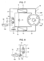
- FIG. 7 An internal constitution diagram of a washing and drying machine W shown in FIG. 7. It is to be noted that in FIG. 7, components denoted with the same reference numerals as those of FIGS. 1 to 6 produce identical or similar effects, and description thereof is omitted.
- Heat exchange means of the present embodiment is constituted of an external heat exchanger 150 for performing heat exchange between outside air as an external heat medium and a refrigerant sucked into a compressor 11.
- the external heat exchanger 150 is disposed midway in a refrigerant introduction tube 30.
- the external heat exchanger 150 is disposed in the outside of an air circulation path 20 in the same manner as in the external heat exchanger 50 of the above embodiment.
- a control unit starts a fan 16 in the air circulation path 20 and a compressor 11 of a refrigerant circuit 10. In consequence, the compressor 11 starts compression of the refrigerant.
- a low-temperature low-pressure refrigerant gas is sucked into a first rotary compression element 32 of the compressor 11.
- the refrigerant gas compressed by the first rotary compression element 32 to obtain an intermediate pressure is sucked into a second rotary compression element 34, and compressed by the element to form a high-temperature high-pressure refrigerant gas.
- the gas is discharged from the compressor 11 via a refrigerant discharge tube 37.
- the refrigerant discharged from the compressor 11 enters a radiator 12, radiates in the radiator, and then reaches an expansion valve 14.
- the pressure of the refrigerant is reduced by the expansion valve 14. In the process, the refrigerant is liquefied, and then enters an evaporator 15.
- the refrigerant absorbs heat from a surrounding area in the evaporator, and evaporates.
- the refrigerant exiting from the evaporator 15 enters the external heat exchanger 150.
- the refrigerant which has entered the external heat exchanger 150 is subjected to heat exchange between the refrigerant and surrounding air (the outside air), and radiates. In consequence, a temperature of the refrigerant sucked into the compressor 11 drops.
- the refrigerant cooled by the external heat exchanger 150 repeats a cycle of being sucked into the first rotary compression element 32 of the compressor 11.
- the external heat exchanger 150 can perform the heat exchange between the refrigerant and the outside air to discard the heat of the refrigerant to the outside air, and the confinement of the heat can be eliminated.
- a discharged refrigerant temperature of the compressor 11 can quickly and precisely be lowered. Therefore, without controlling a capability of the compressor 11 or stopping the compressor as in a conventional technology, the high capability of the compressor 11 can be maintained. In consequence, a drying time can be reduced.
- the whole compressor 11 can be cooled. In consequence, an efficiency of a compressing operation of the compressor 11 can be raised.
- channel control means such as a bypass pipe 136 disposed around the external heat exchanger 150 and valve units 160, 162 may be arranged to open/close the valve units 160, 162 by the control unit as in Embodiment 1, and it may be controlled whether or not to pass the refrigerant through the external heat exchanger 150.
- any refrigerant is not passed through the external heat exchanger 150 in an initial stage of the drying operation, and any heat is not discharged. A temperature rise of the drying air can then be promoted, and this can contribute to the reduction of the drying time.
- the refrigerant is passed through the external heat exchanger 150 in a later stage of the drying operation to discharge the heat, a disadvantage due to the confinement of the heat can be eliminated.
- the refrigerant is allowed to naturally radiate in the external heat exchanger 150, but the present invention is not limited to this embodiment.
- a fan 55 may be disposed in the vicinity of the external heat exchanger 150, and an air flow rate of the fan 55 may be adjusted to thereby control the quantity of radiant heat in the external heat exchanger 150.
- a water cooling type heat exchanges may be constituted, an amount of water flowing through the external heat exchanger 150 may be adjusted by a water supply valve 58 to control the quantity of radiant heat.
- the quantity of radiant heat in the external heat exchanger 150 may be controlled in stages as described above. Even when the quantity of radiant heat in the external heat exchanger 150 is set to be largest and the confinement of the heat is not eliminated yet, control of the number of rotations of the compressor 11 (control to reduce the number) may be performed in a range in which a drying performance does not deteriorate. It is to be noted that in the present embodiment, the compressor 11 is not limited to a two-stages compression type compressor. The present invention is effective even when a single-stage compression type compressor is used.
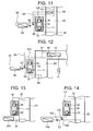
- FIGS. 9 and 10 show that the compressor 11 of a washing and drying machine W of Embodiment 1 is disposed in the outside of the air circulation path 20, FIG. 9 shows that valve units 60, 62 are arranged as channel control means (i.e., the compressor 11 of the washing and drying machine W of FIG. 1 is disposed in the outside of the air circulation path 20), and FIG. 10 is an internal constitution diagram of a case where any channel control means is not disposed.
- FIGS. 9 and 10 show that the compressor 11 of a washing and drying machine W of Embodiment 1 is disposed in the outside of the air circulation path 20
- FIG. 9 shows that valve units 60, 62 are arranged as channel control means (i.e., the compressor 11 of the washing and drying machine W of FIG. 1 is disposed in the outside of the air circulation path 20)
- FIG. 10 is an internal constitution diagram of a case where any channel control means is not disposed.
- FIGS. 11 and 12 are diagrams in which the compressor 11 of the washing and drying machine W of Embodiment 2 is disposed in the outside of the air circulation path 20
- FIG. 11 is a diagram of a case where the compressor 11 of the washing and drying machine W of FIG. 5 is disposed in the outside of the air circulation path 20
- FIG. 12 shows a diagram of a case where the compressor 11 of the washing and drying machine W including an internal heat exchanger 90 of FIG. 6 constituted integrally with a radiator 12 is disposed in the outside of the air circulation path 20.
- FIGS. 13 and 14 are diagrams of a case where the compressor 11 of the washing and drying machine W of Embodiment 3 is disposed in the outside of the air circulation path 20, FIG. 13 shows that any channel control means is not disposed, and FIG.
- valve units 160, 162 are arranged as channel control means. It is to be noted that in FIGS. 9 to 14, components denoted with the same reference numerals as those of FIGS. 1 to 8 produce identical or similar effects, and description thereof is omitted.
- the compressor 11 is disposed in the outside of the air circulation path 20, and a periphery of the compressor 11 is insulated from the outside. That is, a sealed vessel 18 constituting an outer contour of the compressor 11 of the present embodiment is disposed in an external insulation space 120 of the air circulation path 20.
- the compressor 11 is heated by air for drying having its temperature raised in a later stage of a drying operation, and the temperature in the compressor 11 rises. In consequence, a disadvantage that the rise of the refrigerant embodiment is caused can be avoided in advance.
- FIG. 15 An internal constitution diagram of a washing and drying machine W shown in FIG. 15. It is to be noted that in FIG. 15, components denoted with the same reference numerals as those of FIGS. 1 to 14 produce identical or similar effects, and description thereof is omitted.
- heat exchange means is constituted of a heat exchanger 170 for performing heat exchange between an external heat exchange medium and air in an air circulation path 20, and the means is disposed in the air circulation path 20 from a downstream side (an air outlet) of an evaporator 15 to an upstream side (an air inlet) of a radiator 12.
- the heat exchanger 170 is disposed in a position having the lowest temperature in the air circulation path 20 on the upstream side of the compressor 11 on the downstream side of the evaporator 15. Therefore, in a case where a temperature of drying air cooled by the evaporator 15 is lower than that of outside air (room temperature), when the heat exchanger 170 performs the heat exchange between the drying air and the outside air, heat is taken from the outside air to heat the drying air. Therefore, in a situation in which the temperature in the air circulation path 20 is low as in an initial stage of a drying operation, the temperature of the circulated air cooled by the evaporator 15 is as low as about +15°C. Therefore, in the heat exchanger 170, the heat is absorbed from the outside air as an external heat medium.
- the circulated air passed through the evaporator 15 has a temperature of about +50°C. Since the circulated air temperature is higher than that of the output air, the heat exchanger 170 discharge the heat (radiation) to the outside air.
- a washing and drying machine W of the present embodiment constituted as described above during the drying operation. It is to be noted that processes (a washing process, a rinsing process, a spin-drying process, etc.) before the drying operation are the same as those of Embodiment 1 described above, and description thereof is therefore omitted.
- a control unit starts a fan 16 in the air circulation path 20 and the compressor 11 of a refrigerant circuit 10. In consequence, the compressor 11 starts compression of the refrigerant.
- a low-temperature low-pressure refrigerant gas is sucked into a first rotary compression element 32 of the compressor 11.
- the refrigerant gas compressed by the first rotary compression element 32 to obtain an intermediate pressure is sucked into a second rotary compression element 34, and compressed by the element to form a high-temperature high-pressure refrigerant gas.
- the gas is discharged from the compressor 11 via a refrigerant discharge tube 37.
- the refrigerant discharged from the compressor 11 enters the radiator 12, radiates in the radiator, and then reaches an expansion valve 14.
- the pressure of the refrigerant is reduced by the expansion valve 14. In the process, the refrigerant is liquefied, and then enters the evaporator 15.
- the refrigerant which has entered the evaporator 15 absorbs heat from a surrounding area in the evaporator, and evaporates. Subsequently, the refrigerant is sucked into the first rotary compression element 32 of the compressor 11 via a refrigerant introduction tube 30. This cycle is repeated.
- the drying air heated by radiant heat of the high-temperature high-pressure refrigerant gas in the radiator 12 to obtain a high temperature is sent toward an inlet 20A of the air circulation path 20, and discharged from an outlet 20B to a storage chamber 7.
- the drying air discharged to the storage chamber 7 warms an object to be dried stored in an inner drum 5 (the storage chamber 7) to evaporate a moisture, and the object to be dried is dried.
- the humidity-containing air which has dried the object to be dried flows through the storage chamber 7, is discharged from the inner drum 5, returns from the inlet 20A to the air circulation path 20 and passes through the evaporator 15 disposed in the path.
- the moisture (the moisture evaporated from the object to be dried) contained in the air from the storage chamber 7 is condensed on the surface of the evaporator 15 while passing through the evaporator 15, and the moisture falls as water droplets.
- the fallen water droplets are discharged from a water discharge passage to an external drain ditch or the like via a drain pipe (not shown).
- the air from which humidity has been removed to dry by this evaporator 15 next passes through the heat exchanger 170.
- a solid line A shows a transition of a temperature (a sucked refrigerant temperature of a first stage) of the refrigerant sucked into the first rotary compression element 32 in a case where the present invention is applied. It is considered that this indicates substantially the same behavior as that of a temperature transition of the drying air passed through the evaporator 15.
- a solid line B shows a transition of a discharged refrigerant temperature (a discharged refrigerant temperature of a second stage) of the second rotary compression element 34 in a case where the present invention is applied.
- a broken line A shows a transition of a temperature (a sucked refrigerant temperature of a first stage) of a refrigerant sucked into a first rotary compression element in a conventional washing and drying machine
- a broken line B shows a transition of a discharged refrigerant temperature (a discharged refrigerant temperature of a second stage) of a second rotary compression element in the conventional washing and drying machine.
- the temperature of the drying air passed through the evaporator 15 disposed in the air circulation path 20 is lower than that of the outside air (room temperature + 20°C to +25°C).
- the heat exchanger 170 performs heat exchange between the drying air and the outside air, heat is absorbed from the outside air.
- the temperature of the refrigerant discharged from the second rotary compression element 34 in the initial stage of the drying operation can be raised, and a temperature rise of the drying air discharged to the storage chamber 7 can be promoted. Therefore, a drying efficiency of an object to be washed can be improved.
- the drying air passed through the heat exchanger 170 and heated is sucked into the fan 16, then discharged toward the compressor 11, passes around the compressor 11, then enters the radiator 12 to be heated, exits from the outlet 20B of the air circulation path 20, is discharged into the storage chamber 7 of the inner drum 5, and takes the moisture from the object to be dried in the storage chamber 7 to dry the object. This circulation is repeated.
- the heat exchanger 170 can discard the heat of the drying air to the outside air. Therefore, the temperature of the refrigerant sucked into the first rotary compression element 32 can be lowered.
- the heat is taken from the outside air to promote the temperature rise of the drying air in a first stage of the drying operation. Moreover, the heat is discarded to the outside air in the later stage of the drying operation, and the confinement of the heat can be eliminated. Since the temperature of the outside air and the temperature of the drying air are adjusted without switching the radiation and the heat absorption of the heat exchanger 170, optimum control can easily be performed. Therefore, costs can be reduced.
- the heat exchanger as the heat exchange means for the heat exchange between the drying air and the air in the air circulation path 20 is disposed in the air circulation path 20 from the downstream side of the evaporator 15 to the upstream side of the compressor 11.
- the heat exchange means may be disposed at any place between the downstream side of the evaporator 15 and the upstream side of the radiator 12. As shown in FIG. 17, the heat exchange means may be disposed in the air circulation path 20 from the downstream side of the compressor 11 to the upstream side of the radiator 12.
- the washing and drying machine W of the present embodiment is constituted in such a manner that the compressor 11 is disposed in the air circulation path 20.
- the compressor 11 is disposed in the air circulation path 20 in this manner, when the air cooled by the evaporator 15, sucked into the fan 16 and discharged is passed through the periphery of the compressor 11, the compressor 11 heated by the operation can be cooled.
- radiant heat from the compressor 11 itself can be utilized in heating the drying air. In consequence, the temperature rise of the drying air in the initial stage of the drying operation can be promoted.
- the compressor 11 may be disposed in the outside of the air circulation path 20, and the periphery of the compressor 11 may be insulated.
- the compressor 11 is heated by the raised temperature of the drying air in the later stage of the drying operation, and the temperature in the compressor 11 rises. In consequence, it is possible to avoid in advance a disadvantage that the rise of the refrigerant temperature is incurred.
- the two-stages compression type compressor including the first rotary compression element 32 and the second rotary compression element 34 has been used, but the present invention is not limited to this embodiment.
- the present invention is effective, even when a compressor including three or more stages of compression elements is used.
- a single-stage compression type compressor may be used.
Applications Claiming Priority (1)
| Application Number | Priority Date | Filing Date | Title |
|---|---|---|---|
| JP2006012381A JP4386894B2 (ja) | 2006-01-20 | 2006-01-20 | 乾燥機 |
Publications (1)
| Publication Number | Publication Date |
|---|---|
| EP1811076A1 true EP1811076A1 (en) | 2007-07-25 |
Family
ID=38001741
Family Applications (1)
| Application Number | Title | Priority Date | Filing Date |
|---|---|---|---|
| EP07000883A Withdrawn EP1811076A1 (en) | 2006-01-20 | 2007-01-17 | Drying machine |
Country Status (4)
| Country | Link |
|---|---|
| US (1) | US20070169366A1 (ja) |
| EP (1) | EP1811076A1 (ja) |
| JP (1) | JP4386894B2 (ja) |
| CN (1) | CN101012618A (ja) |
Cited By (9)
| Publication number | Priority date | Publication date | Assignee | Title |
|---|---|---|---|---|
| WO2009083170A2 (en) * | 2007-12-31 | 2009-07-09 | Electrolux Home Products Corporation N.V. | Electric household appliance and relative operating method |
| WO2010003936A1 (en) * | 2008-07-07 | 2010-01-14 | Arcelik Anonim Sirketi | A heat pump type dryer |
| WO2010012708A1 (de) * | 2008-07-30 | 2010-02-04 | BSH Bosch und Siemens Hausgeräte GmbH | Trocknungsverfahren und kondensationstrockner mit einer wärmepumpe und system zur erkennung eines unzulässigen betriebszustands |
| WO2012059352A3 (de) * | 2010-11-05 | 2012-12-06 | BSH Bosch und Siemens Hausgeräte GmbH | Trocknungseinrichtung und hausgerät mit einer solchen trocknungseinrichtung |
| EP2540905A1 (en) * | 2011-06-29 | 2013-01-02 | Electrolux Home Products Corporation N.V. | A laundry dryer with heat pump system |
| EP2551402A1 (en) * | 2011-07-28 | 2013-01-30 | Electrolux Home Products Corporation N.V. | A heat pump system for a laundry dryer |
| DE102011085468A1 (de) * | 2011-10-28 | 2013-05-02 | BSH Bosch und Siemens Hausgeräte GmbH | Wäschetrocknungsgerät mit einer Wärmepumpe und einem Antrieb der Wärmepumpe |
| EP2415927A3 (en) * | 2010-08-06 | 2015-08-19 | Panasonic Corporation | Dehumidifying-warming apparatus and clothes drier |
| CN110629481A (zh) * | 2018-06-21 | 2019-12-31 | 青岛海尔洗衣机有限公司 | 一种干燥设备 |
Families Citing this family (16)
| Publication number | Priority date | Publication date | Assignee | Title |
|---|---|---|---|---|
| JP4326445B2 (ja) * | 2004-10-20 | 2009-09-09 | 三洋電機株式会社 | 洗濯乾燥機 |
| JP2009097847A (ja) * | 2007-09-28 | 2009-05-07 | Daikin Ind Ltd | 冷凍装置 |
| JP5141269B2 (ja) * | 2008-01-30 | 2013-02-13 | ダイキン工業株式会社 | 冷凍装置 |
| JP2010131262A (ja) * | 2008-12-05 | 2010-06-17 | Sanyo Electric Co Ltd | 衣類乾燥機 |
| US8943843B2 (en) * | 2009-12-01 | 2015-02-03 | Budhi HARYANTO | Energy-saving and environmentally-friendly multipurpose air conditioning as a generator of dew drinking water, hot water and dryer |
| KR101224054B1 (ko) * | 2010-09-30 | 2013-01-22 | 엘지전자 주식회사 | 의류처리장치 및 의류처리장치의 운전방법 |
| JP2012125352A (ja) * | 2010-12-14 | 2012-07-05 | Samsung Electronics Co Ltd | 衣類乾燥機 |
| JP5625883B2 (ja) * | 2010-12-21 | 2014-11-19 | パナソニック株式会社 | 除湿加温装置および同装置を備えた衣類乾燥機 |
| EP2691568B1 (en) | 2011-03-29 | 2017-12-27 | LG Electronics Inc. | Controlling method for a clothes dryer |
| EP2573253B1 (en) * | 2011-09-26 | 2016-09-07 | Electrolux Home Products Corporation N.V. | Heat pump dryer |
| CN103335458A (zh) * | 2013-07-04 | 2013-10-02 | 天津商业大学 | 二次节流双级压缩制冷系统 |
| EP3124680B1 (en) * | 2015-07-27 | 2018-06-20 | Electrolux Appliances Aktiebolag | Method for adapting operation parameters during drying in a heat pump dryer |
| WO2019105526A1 (en) * | 2017-11-28 | 2019-06-06 | Electrolux Laundry Systems Sweden Ab | Tumble dryer |
| CN109163517B (zh) * | 2018-09-30 | 2024-01-30 | 广州万二二麦工程技术有限公司 | 一种具有烘干和冷谷功能的谷物储存装置 |
| CN109813096B (zh) * | 2019-03-18 | 2024-04-02 | 青岛大学 | 多次混风部分除湿热泵干燥系统 |
| CN114080529B (zh) * | 2019-06-28 | 2023-10-10 | 大金工业株式会社 | 冷冻装置 |
Citations (5)
| Publication number | Priority date | Publication date | Assignee | Title |
|---|---|---|---|---|
| EP1273468A1 (en) * | 2001-02-13 | 2003-01-08 | Sanyo Electric Co., Ltd. | On-vehicle air conditioner |
| US20030056393A1 (en) * | 2001-09-25 | 2003-03-27 | Lee Won Hee | Washing/drying machine and clothes dryer |
| EP1493860A2 (en) * | 2003-06-30 | 2005-01-05 | SANYO ELECTRIC Co., Ltd. | Dryer |
| US20050044744A1 (en) * | 2003-08-07 | 2005-03-03 | Masaya Tadano | Drying apparatus |
| EP1550829A1 (en) * | 2002-09-26 | 2005-07-06 | Matsushita Electric Industrial Co., Ltd. | Drying apparatus |
Family Cites Families (4)
| Publication number | Priority date | Publication date | Assignee | Title |
|---|---|---|---|---|
| US2721728A (en) * | 1951-10-12 | 1955-10-25 | Henry B Higgins | Heat concentrator |
| US4621438A (en) * | 1980-12-04 | 1986-11-11 | Donald M. Thompson | Energy efficient clothes dryer |
| US6658888B2 (en) * | 2002-04-10 | 2003-12-09 | Carrier Corporation | Method for increasing efficiency of a vapor compression system by compressor cooling |
| TWI301188B (en) * | 2002-08-30 | 2008-09-21 | Sanyo Electric Co | Refrigeant cycling device and compressor using the same |
-
2006
- 2006-01-20 JP JP2006012381A patent/JP4386894B2/ja not_active Expired - Fee Related
-
2007
- 2007-01-17 CN CNA2007100022693A patent/CN101012618A/zh active Pending
- 2007-01-17 EP EP07000883A patent/EP1811076A1/en not_active Withdrawn
- 2007-01-19 US US11/655,165 patent/US20070169366A1/en not_active Abandoned
Patent Citations (5)
| Publication number | Priority date | Publication date | Assignee | Title |
|---|---|---|---|---|
| EP1273468A1 (en) * | 2001-02-13 | 2003-01-08 | Sanyo Electric Co., Ltd. | On-vehicle air conditioner |
| US20030056393A1 (en) * | 2001-09-25 | 2003-03-27 | Lee Won Hee | Washing/drying machine and clothes dryer |
| EP1550829A1 (en) * | 2002-09-26 | 2005-07-06 | Matsushita Electric Industrial Co., Ltd. | Drying apparatus |
| EP1493860A2 (en) * | 2003-06-30 | 2005-01-05 | SANYO ELECTRIC Co., Ltd. | Dryer |
| US20050044744A1 (en) * | 2003-08-07 | 2005-03-03 | Masaya Tadano | Drying apparatus |
Cited By (14)
| Publication number | Priority date | Publication date | Assignee | Title |
|---|---|---|---|---|
| WO2009083170A3 (en) * | 2007-12-31 | 2009-08-27 | Electrolux Home Products Corporation N.V. | Electric household appliance and relative operating method |
| WO2009083170A2 (en) * | 2007-12-31 | 2009-07-09 | Electrolux Home Products Corporation N.V. | Electric household appliance and relative operating method |
| WO2010003936A1 (en) * | 2008-07-07 | 2010-01-14 | Arcelik Anonim Sirketi | A heat pump type dryer |
| WO2010012708A1 (de) * | 2008-07-30 | 2010-02-04 | BSH Bosch und Siemens Hausgeräte GmbH | Trocknungsverfahren und kondensationstrockner mit einer wärmepumpe und system zur erkennung eines unzulässigen betriebszustands |
| CN102112677B (zh) * | 2008-07-30 | 2012-11-28 | Bsh博世和西门子家用器具有限公司 | 烘干方法、包括热泵的冷凝式烘干机以及用于识别不允许的操作状态的系统 |
| EP2415927A3 (en) * | 2010-08-06 | 2015-08-19 | Panasonic Corporation | Dehumidifying-warming apparatus and clothes drier |
| EP2415928A3 (en) * | 2010-08-06 | 2015-09-02 | Panasonic Corporation | Dehumidifying-warming apparatus and clothes dryer using the same |
| WO2012059352A3 (de) * | 2010-11-05 | 2012-12-06 | BSH Bosch und Siemens Hausgeräte GmbH | Trocknungseinrichtung und hausgerät mit einer solchen trocknungseinrichtung |
| EP2540905A1 (en) * | 2011-06-29 | 2013-01-02 | Electrolux Home Products Corporation N.V. | A laundry dryer with heat pump system |
| WO2013014145A1 (en) * | 2011-07-28 | 2013-01-31 | Electrolux Home Products Corporation N.V. | A heat pump system for a laundry dryer |
| EP2551402A1 (en) * | 2011-07-28 | 2013-01-30 | Electrolux Home Products Corporation N.V. | A heat pump system for a laundry dryer |
| DE102011085468A1 (de) * | 2011-10-28 | 2013-05-02 | BSH Bosch und Siemens Hausgeräte GmbH | Wäschetrocknungsgerät mit einer Wärmepumpe und einem Antrieb der Wärmepumpe |
| CN110629481A (zh) * | 2018-06-21 | 2019-12-31 | 青岛海尔洗衣机有限公司 | 一种干燥设备 |
| CN110629481B (zh) * | 2018-06-21 | 2023-07-07 | 青岛海尔洗衣机有限公司 | 一种干燥设备 |
Also Published As
| Publication number | Publication date |
|---|---|
| JP2007190256A (ja) | 2007-08-02 |
| JP4386894B2 (ja) | 2009-12-16 |
| US20070169366A1 (en) | 2007-07-26 |
| CN101012618A (zh) | 2007-08-08 |
Similar Documents
| Publication | Publication Date | Title |
|---|---|---|
| EP1811077B1 (en) | Drying machine | |
| EP1811076A1 (en) | Drying machine | |
| US7322123B2 (en) | Drying machine | |
| US6981336B2 (en) | Washing/drying machine | |
| JP4889545B2 (ja) | 乾燥装置及びこの装置を備えた洗濯乾燥機 | |
| US8393172B2 (en) | Heat pump drying machine | |
| US20050199016A1 (en) | Dry cleaner and drying machine | |
| US20060080974A1 (en) | Drying apparatus, washing/drying apparatus, and operation methods of the apparatuses | |
| US6904703B2 (en) | Dry cleaning machine | |
| JP4266903B2 (ja) | 洗濯乾燥機 | |
| US20050086824A1 (en) | Dryer | |
| JP2007143720A (ja) | 衣類乾燥装置 | |
| JP4984924B2 (ja) | 衣類乾燥装置および同装置を備えた洗濯乾燥機 | |
| JP2007143712A (ja) | 洗濯乾燥機 | |
| JP2006181219A (ja) | 乾燥機 | |
| JP2005027934A (ja) | 乾燥機 | |
| JP2005069539A (ja) | 乾燥機 | |
| JP4082389B2 (ja) | ヒートポンプ給湯装置 | |
| JP2006272025A (ja) | 乾燥機 | |
| JP2010220873A (ja) | 衣類乾燥機 | |
| JP3448897B2 (ja) | ヒートポンプ式冷暖房給湯装置 | |
| CN115325609A (zh) | 空调器和空调器的控制方法 | |
| JP2009050353A (ja) | 乾燥機 | |
| JP4447034B2 (ja) | 乾燥機 | |
| JP2005046354A (ja) | 乾燥機 |
Legal Events
| Date | Code | Title | Description |
|---|---|---|---|
| PUAI | Public reference made under article 153(3) epc to a published international application that has entered the european phase |
Free format text: ORIGINAL CODE: 0009012 |
|
| AK | Designated contracting states |
Kind code of ref document: A1 Designated state(s): AT BE BG CH CY CZ DE DK EE ES FI FR GB GR HU IE IS IT LI LT LU LV MC NL PL PT RO SE SI SK TR |
|
| AX | Request for extension of the european patent |
Extension state: AL BA HR MK YU |
|
| 17P | Request for examination filed |
Effective date: 20070816 |
|
| 17Q | First examination report despatched |
Effective date: 20070927 |
|
| AKX | Designation fees paid |
Designated state(s): DE FR GB |
|
| STAA | Information on the status of an ep patent application or granted ep patent |
Free format text: STATUS: THE APPLICATION HAS BEEN WITHDRAWN |
|
| 18W | Application withdrawn |
Effective date: 20090120 |