EP1810802A1 - Machine-outil - Google Patents
Machine-outil Download PDFInfo
- Publication number
- EP1810802A1 EP1810802A1 EP07000995A EP07000995A EP1810802A1 EP 1810802 A1 EP1810802 A1 EP 1810802A1 EP 07000995 A EP07000995 A EP 07000995A EP 07000995 A EP07000995 A EP 07000995A EP 1810802 A1 EP1810802 A1 EP 1810802A1
- Authority
- EP
- European Patent Office
- Prior art keywords
- machine according
- clamping
- elongated
- elements
- along
- Prior art date
- Legal status (The legal status is an assumption and is not a legal conclusion. Google has not performed a legal analysis and makes no representation as to the accuracy of the status listed.)
- Withdrawn
Links
Images

Classifications
-
- B—PERFORMING OPERATIONS; TRANSPORTING
- B27—WORKING OR PRESERVING WOOD OR SIMILAR MATERIAL; NAILING OR STAPLING MACHINES IN GENERAL
- B27M—WORKING OF WOOD NOT PROVIDED FOR IN SUBCLASSES B27B - B27L; MANUFACTURE OF SPECIFIC WOODEN ARTICLES
- B27M1/00—Working of wood not provided for in subclasses B27B - B27L, e.g. by stretching
- B27M1/08—Working of wood not provided for in subclasses B27B - B27L, e.g. by stretching by multi-step processes
-
- B—PERFORMING OPERATIONS; TRANSPORTING
- B27—WORKING OR PRESERVING WOOD OR SIMILAR MATERIAL; NAILING OR STAPLING MACHINES IN GENERAL
- B27F—DOVETAILED WORK; TENONS; SLOTTING MACHINES FOR WOOD OR SIMILAR MATERIAL; NAILING OR STAPLING MACHINES
- B27F1/00—Dovetailed work; Tenons; Making tongues or grooves; Groove- and- tongue jointed work; Finger- joints
- B27F1/02—Making tongues or grooves, of indefinite length
Definitions
- the invention relates to a machine tool, in particular a machine tool arranged for machining elongated elements, such as, for example, workpieces made of wood or similar materials.
- Such elongated elements comprises parallelpipedon-shaped elements intended for being used as uprights and crosspieces in frames of windows, doors or the like.
- the invention further relates to a method for machining such elongated elements.
- the minimum operations provided for making an elongated element into a semifinished product and then into a finished product may comprise machinings performed on front end portions of the aforesaid elongated element, said also "front-end" machinings, such as for example cutting and/or tenoning, and operations performed along a longitudinal development of the aforesaid elongated element, for example profiling and/or slotting and/or drilling.
- EP 1281491 teaches a machine for machining elongated elements extending longitudinally made of wood, plastics, or similar materials, having a profiling unit provided with at least a spindle arranged for performing longitudinal profiling of the aforesaid workpieces.
- This machine is further provided with an advancing unit arranged for moving an elongated element to the profiling unit along a longitudinal advancing direction.
- the advancing unit comprises upper clamping jaws arranged above the elongated element and lower clamping jaws arranged below the elongated element, cooperating together to clamp the elongated element during an advancing step and a machining step.
- the upper clamping jaws and the lower clamping jaws are positioned on the advancing unit in such a way that, in a plan view, the upper clamping jaws are staggered with respect to the lower clamping jaws.
- the upper clamping jaws and the lower clamping jaws in a plan view, have a profile with a complementary shape.
- the aforesaid upper and lower clamping jaws are further arranged in a row on the aforesaid advancing unit along the longitudinal advancing direction.
- a drawback of the machines made according to EP 1281491 consists of the presence of a clamping zone, extending prevalently longitudinally, in which it is not possible to machine the elongated element.
- the further advancing unit removes the elongated elements first clamped in the advancing unit, clamps this elongated elements between further jaws in a further clamping zone, opposite the aforesaid clamping zone, and advances this elongated elements to a further profiling unit that is longitudinally advanced with respect to the aforesaid profiling unit, arranged for machining the elongated elements in the clamping zone that had already been clamped between the upper clamping jaws and the lower clamping jaws.
- a further advancing unit entails an increase in the costs to be sustained to make such a machine and increases the overall dimensions thereof.
- a further drawback of the machines made according to EP 1281491 consists of the possibility of machining only one elongated element a time, with consequent reduced machine productive capacity.
- a still further drawback relates to the constructional complexity of the known machines.
- An object of the invention is to improve the machine tools arranged for machining elongated elements made of wood or similar materials.
- a further object is to make machine tools that enable productive capacity to be increased with respect to known machine tools.
- a still further object is to make machine tools that are cheap and easy to make.
- a further object is to make machine tools with limited overall dimensions.
- a further object is to improve the machining methods for machining elongated elements.
- a machine tool for machining elongated elements made of wood or similar materials comprising retaining means arranged for clamping and moving said elongated elements along a first longitudinal direction and provided with a plurality of clamps, each clamp comprising clamping elements arranged for clamping said elongated elements therebetween, characterised in that said clamping elements, in a plan view, substantially occupy the same overall dimensions.
- the retaining means may for example comprise four clamps that are equidistant from one another and movable along the aforesaid first longitudinal direction.
- Each clamp is then provided with a pair of jaws facing one another and extending along a second direction, that is transverse with respect to the first direction.
- the shape of the jaws and in particular the reduced extent along the first longitudinal direction, and the mutual distance between two consecutive clamps, enables a clamping zone to be greatly reduced that is required for clamping the elongated elements and correspondingly increasing a free surface of the elongated elements that it is possible to machine.
- a machine tool for machining elongated elements made of wood or similar materials comprising retaining means arranged for clamping and moving said elongated elements along a first longitudinal direction comprising at least a clamp comprising clamping elements arranged for clamping said elongated elements therebetween, characterised in that it further comprises an abutting element movable along a second direction, that is transverse to said first direction, with respect to said clamping elements.
- the retaining means comprises an active portion arranged for clamping an elongated element to be machined and a further portion, adjacent to the active portion, provided with an unloading belt arranged for unloading an elongated element that has already been machined.
- a method for machining elongated elements made of wood or similar materials defining a first longitudinal direction comprising retaining said elongated elements in a clamping element of first retaining means in such a way that a first elongated element of said elongated elements protrudes along a second direction, that is transverse to said first direction, by a certain amount from said clamping element, approaching along said second direction said first retaining means to second retaining means suitable for receiving and retaining said elongated elements, releasing said clamping element, moving away along said second direction said clamping element from said second retaining means by a further certain amount, characterised in that said moving away comprises maintaining an abutting element of said first retaining means locked along said second direction in such a way that a second elongated element of said elongated elements protrudes from said clamping element substantially by said certain amount.
- the elongated elements are in groups of three elements, it is possible to transfer a first elongated element from the first retaining means to the second retaining means, machining a face of the first elongated element whilst the first elongated element is clamped in the active portion of the second retaining means and simultaneously machine also a second face opposite the first face of a second elongated element whilst the second elongated element is clamped by the first retaining means.
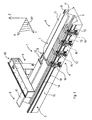
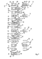
- FIG. 1 With reference to Figure 1 there is shown a machine tool 1 arranged for machining elongated elements 2, made of wood or similar materials, extending prevalently along a first longitudinal direction X.
- the elongated elements 2 for example parallelpipedon-shaped, can be grouped in groups of free elements, and, after suitable machinings, can be subsequently used as uprights or crosspieces in window frames, doors or the like.
- the machine tool 1 is arranged for performing on the elongated elements 2 machinings such as, for example, cutting, tenoning, drilling and milling.
- the machine tool 1 comprises a base 3 extending prevalently along the aforesaid first direction X.
- a loading station 4 in which the elongated elements 2 are loaded on the machine tool 1, and a first working station 5, in which the elongated elements 2 are machined.
- the first working station 5 further comprises an unloading zone 6 in which the elongated elements 2 are unloaded from the machine tool 1.
- the base 3 supports, substantially at the loading station 4, a drawing near element 7, extending along the first direction X, for example of pneumatic type.
- the drawing near element 7 is arranged for receiving and moving the elongated elements 2 on the machine tool 1 and is movable along a second transverse direction Y that is substantially perpendicular with respect to the first direction X, between a first loading position G (represented by a broken line) in which the elongated elements 2 are loaded onto a loading belt 8 and a first unloading position H in which the elongated elements 2 are unloaded from the loading belt 8 ( Figure 4).
- the loading belt 8 extends along the first direction X and is arranged for advancing the elongated elements 2 along a direction substantially parallel to the aforesaid first direction X.
- the loading belt 8 further comprises an end 9 provided with a first abutment 10, extending along the second direction Y, used as an abutment during a loading step for loading the elongated elements 2.
- the drawing near element 7 further comprises a pusher 11, having a substantially trapezoidal shape, extending along the first direction X, arranged for pushing transversely the elements 2 along the aforesaid second direction Y.
- the pusher 11 is movable with respect to the loading belt 8 towards and away from a clamping and movement device 12 arranged for receiving, retaining and moving the elongated elements 2.
- the device 12 is movable along the first direction X by means of sliding blocks 13 that are slidable along guides 14 obtained in a side surface 15 of the base 3.
- the device 12 is movable between a first operating position A (represented by a broken line), in which the device 12 is positioned substantially at the aforesaid loading station 4 and faces the drawing near element 7, and a second operating position B, in which the device 12 is positioned substantially at the aforesaid first working station 5 ( Figure 4).
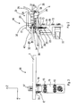
- the device 12 comprises a plurality of clamps 16, for example four in number, arranged in such a way as to define a row along the aforesaid first direction X, shown in detail in Figures 2 and 3.
- Each clamp 16 comprises a frame 19, extending along a third substantially vertical direction Z, provided with a first face 20 on which are positioned the aforesaid sliding blocks 13 and a second face 21, opposite the aforesaid first face 20, on which further guides 22 are positioned.
- the further guides 22 are slidingly associated with a sliding block element 23.
- the sliding block element 23 is associated with an upright element 26 of a first upper jaw 17 with which the clamp 16 is provided.
- the first jaw 17, extending substantially parallel to the second direction Y, has substantially the shape of an upturned "L” and is provided with a first active surface 24 arranged for contacting an upper transverse portion 25 of the elongated elements 2.
- a second lower jaw 18 extending substantially parallel to the second direction Y, provided with a second active surface 27, facing the first active surface 24, arranged for contacting a further lower transverse portion 28 of the elongated elements 2.
- the second active surface 27 comprises an end zone 30 provided with a second abutment 29 used as an abutment during a transferring step of the elongated elements 2 from the drawing near element 7 to the device 12, as will be disclosed better below.
- the first jaw 17 and the second jaw 18 face one another in such a way that, in a plan view, the first jaw 17 and the second jaw 18 substantially occupy the same overall dimensions.
- first jaw 17 is movable, through an actuator 31 (for example pneumatic), substantially parallel to the third direction Z, between a clamping position and a resting position D ( Figure 2), in which respectively the active surface 24 presses, and does not press, onto the transverse portion 25 of the elongated elements 2.
- actuator 31 for example pneumatic
- Each clamp 16 further comprises an ejecting element 33 positioned between the first jaw 17 and the second jaw 18, extending substantially along the second direction Y, provided with a pad 43.
- the pad 43 is moved by a further actuator 44, for example pneumatic, along the second direction Y and is arranged for contacting a vertical portion 34 of the elongated elements 2.
- Each clamp 16 further comprises a pair of arresting teeth 35 positioned in a further end zone 90, opposite the aforesaid end zone 30 substantially laterally with respect to the second jaw 18, arranged for contacting a further vertical portion 37 of the elongated elements 2, opposite the vertical portion 34, to lock the elongated elements 2 transversely.
- the arresting teeth 35 are movable between a further clamping position (not shown) and a further resting position E ( Figures 2 and 3), in which the arresting teeth 35 are respectively in contact and not in contact with the further vertical portion 37.
- the arresting teeth 35 are moved between the further resting position E and the further clamping position through another actuator 36, for example pneumatic.
- Each clamp 16 is further moved along a direction substantially parallel to the first direction X through motor means 32.
- each clamp 16 is movable along the axis X in an independent manner from one another.
- the machine tool 1 further comprises a first portal 40 positioned in the first working station 5 ( Figure 1).
- the first portal 40 is movable along the base 3 along the first direction X and supports a working unit 46, shown in Figure 4, movable along the first direction X, the second direction Y and the third direction Z, arranged for machining the elongated elements 2.
- the working unit 46 may comprise an electric spindle with which operating heads can be associated, for example milling units, facing tools, tenoning tools, drilling tools, etc, arranged for enabling the desired machinings to be performed.
- the machine tool 1 is further provided with an unloading belt 41 positioned in the first working station 5 that is longitudinally advanced with respect to the drawing near element 7.
- the unloading belt 41 extends along the first direction X and is arranged for receiving and subsequently advancing the elongated elements 2 in a direction substantially parallel to the aforesaid first direction X towards the unloading zone 6, in such a way as to unload the elongated elements from the machine tool 1.
- the unloading belt 41 is further movable along the second direction Y between a second loading position I (represented by a broken line) in which the unloading belt 41 receives the elongated elements 2 from the device 12, and a second unloading position L in which the unloading belt 41 unloads the aforesaid elongated elements 2 from the machine tool 1, which are shown in Figure 4.
- the elongated elements 2 for example in groups of three elements mutually drawn near along the first direction X, are arranged on the drawing near element 7 positioned in the first loading position G.
- the elongated elements 2 are positioned on the loading belt 8, which advances the elongated elements 2 along the first direction X until an end portion 42 of the elongated elements 2 abuts on the first abutment 10.
- the loading belt 8 stops and the drawing near element 7 is positioned in the first unloading position H approaching the device 12 positioned in the first operating position A.
- the arresting teeth 35 are positioned in the further resting position E and the first jaw 17 of each clamp 16 is positioned in the resting position D, in such a way as to be suitable for receiving the elongated elements 2.
- the pusher 11 pushes the elongated elements 2 towards the device 12, until a first longitudinal side 45 of a first elongated element 44 of the aforesaid elongated elements 2 abuts on the second abutment 29.
- the arresting teeth 35 are positioned in the further clamping position to lock the elongated elements 2 transversally.
- first jaws 17 are positioned in the clamping position in such a way as to lock the elongated elements 2 transversely and longitudinally.
- the device 12 is positioned in the second operating position B in such a way that the working unit 46 can perform the desired machinings, the drawing near element 7 is repositioned in the first loading position G, whilst the unloading belt 41 is positioned in the second unloading position L.
- the unloading belt 41 is positioned in the second loading position approaching the device 12 to receive the elongated elements 2.
- the first jaws 17 are repositioned in the resting position D, the arresting teeth 35 are positioned in the further resting position E and the ejecting elements 33 of the clamps 16 are driven that push the elongated elements 2 onto the unloading belt 41 along the second direction Y.
- the unloading belt 41 is positioned in the second unloading position L and is driven to make the elongated elements 2 slide to the unloading zone 6.
- a second group of elongated elements can be loaded onto the loading belt 8 in "masked time".
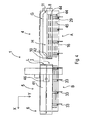
- a machine tool 1' which differs from the machine tool 1 shown in Figure 1, inasmuch as the machine tool 1' is devoid of the unloading belt 41 and of the unloading zone 6 and is provided with a second working station 50 that is longitudinally advanced with respect to the first working station 5 along the base 3, arranged for performing, for example, a profiling on the elongated elements 2.
- the second working station 50 is provided with first retaining means 52 and with second retaining means 53 extending along the first direction X, arranged for receiving, retaining and moving the elongated elements 2.
- the first retaining means 52 is movable along the first direction X between a third loading position M (represented by a broken line) and a third unloading position N, in which the first retaining means 52 are respectively positioned in the first working station 5 and in the second working station 50.
- the first retaining means 52 in the third loading position M, is substantially opposite and coplanar with the device 12, whilst in the third unloading position N, the first retaining means 52 is substantially opposite and coplanar with the second retaining means 53.
- the first retaining means 52 is movable along the second direction Y, when positioned in the third loading position M, between a first transverse position R and a second transverse position S, for receiving from the device 12, as will be better disclosed below, the elongated elements 2.
- the first retaining means 52 is movable along the second direction Y, even when in the third unloading position N, towards and away from the second retaining means 53 to enable the elongated elements 2 to be machined by the working unit 46 and to be transferred to the second transferring means 53.
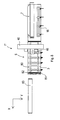
- the first retaining means 52 comprises a clamping element 51 arranged for clamping the elongated elements 2.
- the clamping element 51 comprises a first upper wall 54 and a second lower wall 55 that are opposite one another and substantially parallel, extending longitudinally and substantially parallel to a plane XY.
- the first wall 54 and the second wall 55 are moved along the third direction Z between a clamping position and a releasing position, that are not shown, in which the first wall 54 and the second wall 55 respectively clamp and release the elongated elements 2, through actuating means, for example pneumatic actuating means, that are not shown.
- actuating means for example pneumatic actuating means
- the clamping element 51 is further movable along the second direction Y with respect to an abutting element 56 of the first retaining means 52.
- the abutting element 56 extending longitudinally and interposed between the first wall 54 and the second wall 55, can be moved along the second direction Y with respect to the clamping element 51.
- the second retaining means 53 comprises a further clamping element 59 arranged for clamping the elongated elements 2.
- the further clamping element 59 comprises a third upper wall 57 and a fourth lower wall 58 that are opposite one another and are substantially parallel, extending longitudinally and substantially parallel to a plane XY.
- the third wall 57 and the fourth wall 58 are moved along the third direction Z between a further clamping position and a further releasing position, which are not shown, in which respectively the third wall 57 and the fourth wall 58 clamp and release the elongated elements 2, through further actuating means, for example pneumatic actuating means, which are not shown.
- the third wall 57 and the fourth wall 58 comprise respective end portions comprising respectively an active portion 60 and a further active portion 61, facing one another, arranged for contacting the elongated elements 2 during a clamping step.
- the fourth wall 58 further comprises a further unloading belt 62, adjacent to and substantially coplanar with the further active portion 61, and positioned downstream of the latter, with respect to the second direction Y.
- the further unloading belt 62 extends longitudinally and is arranged for advancing, at the end of machining, the elongated elements 2 along the first direction X to a further unloading zone 63 and then evacuating the latter from the machine tool 1', as disclosed below.
- the first wall 54, the second wall 55, the active portion 60 and the further active portion 61 can provide an irregular profile 64, for example serrated, to encourage the clamping of the elongated elements 2.
- the working unit 46 has performed the desired operations on the elongated elements 2, for example machinings such as cutting, tenoning, drilling, milling in the first working station 5, the elongated elements 2 can be transferred from the device 12 to the first retaining means 52.
- the first retaining means 52 is positioned in the third loading position M and in the first transverse position R, with the first wall 54 and the second wall 55 positioned in the releasing position, in such a way as to be able to receive the elongated elements 2.
- the first jaws 17 of the device 12 are positioned in the resting position D, the arresting teeth 35 are positioned in the further resting position E and the ejecting elements 33 of the clamps 16 are driven that push the elongated elements 2 to the first retaining means 52 until the elongated elements 2 abut on the abutting element 56.
- first wall 54 and the second wall 55 are positioned in the clamping position to clamp the elongated elements 2, and still subsequently the first retaining means 52 is positioned in the second transverse position S.
- the device 12 is repositioned in the first operating position A to receive further elongated elements to be machined.
- the first clamping means 52 is positioned in the third unloading position N, and the first portal 40 is positioned in the second working station 50.
- the machine tool 1' is provided with a first portal arranged for machining the elongated elements in the first working station 5 and of a second portal arranged for machining the elongated elements in the second working station 50, in such a way as to significantly increase the productive capacity of the machine tool 1'.
- the working unit 46 can machine the first longitudinal side 45 of the first elongated element 44, the first elongated element 44 being retained by the clamping element 51 in such a way that the first elongated element 44 protrudes from the latter by a certain amount AA along the second direction Y ( Figure 7a).
- the first retaining means 52 approaches the second retaining means 53 in such a way that the first elongated element 44 is received, at least partially, between the active portion 60 and the further active portion 61 positioned in the further release position.
- the active portion 60 and the further active portion 61 are positioned in the still further clamping position and still subsequently the first wall 54 and the second wall 55 are positioned in the releasing position.
- the abutting element 56 Whilst the clamping element 51 moves away from the aforesaid second retaining means 53, the abutting element 56 remains fixed with respect to the latter in such a way that a second elongated element 70 of said elongated elements 2 protrudes from the clamping element 51 substantially by that certain amount AA.
- first wall 54 and the second wall 55 are positioned in the clamping position.
- the working unit 46 can machine a second longitudinal side 71 of the first elongated element 44 opposite and substantially parallel to the first longitudinal side 45, and a third longitudinal side 72 of the second elongated element 70 facing the second longitudinal side 71.
- the working unit 46 can substantially perform at the same time the required machinings on the second longitudinal side 71 and on the third longitudinal side 72.
- the first transferring means 52 is moved again to the second retaining means 53 ( Figure 7e) in such a way that the second elongated element 70 is positioned almost in contact with the first elongated element 44.
- the active portion 60 and the further active portion 61 are positioned in the further releasing position and the first retaining means 52 are moved nearer the second retaining means 53 ( Figure 7f), in such a way that the first elongated element 44 is pushed by the second elongated element 70 on the further unloading belt 62.
- the active portion 60 and the further active portion 61 are positioned in the further clamping position, after which the further unloading belt 62 evacuates the first elongated element 44 from the machine tool 1'.
- the abutting element 56 Whilst the clamping element 51 moves away from the aforesaid second retaining means 53, the abutting element 56 remains fixed in respect to the latter in such a way that a third elongated element 73 of said elongated elements 2 protrudes from the clamping element 51 substantially by that certain amount AA.
- first wall 54 and the second wall 55 are positioned in the clamping position.
- the working unit 46 can machine a fourth longitudinal side 74 of the second elongated element 70 opposite and substantially parallel to the third longitudinal side 72, and a fifth longitudinal side 75 of the third elongated element 73 facing the fourth longitudinal side 74.
- the working unit 46 can substantially perform at the same time the required machinings on the fourth longitudinal side 74 and on the fifth longitudinal side 75.
- the first retaining means 52 again approaches the second retaining means 53 ( Figure 7i), in such a way that the third elongated element 73 is positioned almost in contact with the second elongated element 70.
- the active portion 60 and the further active portion 61 are positioned in the further releasing position and the first retaining means 52 are moved nearer the second retaining means 53 ( Figure 71), in such a way that the second elongated element 70 is pushed by the third elongated element 73 onto the further unloading belt 62.
- the active portion 60 and the further active portion 61 are positioned in the further clamping position, after which the further unloading belt 62 evacuates the second elongated element 70 from the machine tool 1'.
- first wall 54 and the second wall 55 are positioned in the releasing position and the first retaining means 52, devoid of elongated elements 2, moves away from the second retaining means 53, in the third unloading position N ( Figure 7m), and the abutting element 56 is moved along the second direction Y with respect to the clamping element 51, in such a way that the second retaining means 52 is suitable for receiving further elongated elements 2'.
- the working unit 46 can machine a sixth longitudinal side 77 of the third elongated element 73 opposite and substantially parallel to the fifth longitudinal side 75.
- two situations may occur: a first case in which during machining of the sixth longitudinal side 77 the further elongated elements 2' are loaded in "masked time" and a second case in which the first retaining means 52 are not loaded with further elongated elements 2'.
- the third elongated element 73 is positioned on the further unloading belt 56 by a fourth elongated element 76, in a similar manner to what has been said previously for the first elongated element 44 and the second elongated element 70.
- the abutting element 56 interacts with the sixth longitudinal side 77 and pushes the third elongated element 73 onto the further unloading belt 62, which evacuates the third elongated element 73 from the machine tool 1'.
- an elongated element passes from the first retaining means 52 to the second retaining means 53, always with the elongated element locked, which entails good movement precision.
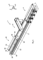
- a machine tool 1" which differs from the machine tool 1 shown in Figure 1, inasmuch as the machine tool 1" is provided with a multifunctional plane 80, extending along the first direction X and supported by the base 3, positioned in the first working station 5.
- the machine tool 1" is arranged for performing, for example, cutting, tenoning, drilling, milling, profiling, rabetting and pantograph machinings on the elongated elements 2.
- the multifunctional plane 80 comprises a plurality of bars 81 extending substantially parallel to the second direction Y and adjustable parallel to the first direction X.
- the bars 81 are arranged for supporting the elongated elements 2, which can be handled and positioned manually by an operator.
- Each bar 81 can be provided with gripping elements 82 arranged for retaining the elongated elements 2 during the aforesaid machinings, comprising for example suction cups or clamps.
- the elongated elements 2 are evacuated from the machine tool 1" through a still further unloading belt 83.
- the multifunctional plane 80 may not be supported by the base 3 and may be positioned substantially parallel to the latter.
- the multifunctional plane 80 can be associated with the machine tool in one of the manners disclosed above.
Applications Claiming Priority (1)
| Application Number | Priority Date | Filing Date | Title |
|---|---|---|---|
| ITMO20060021 ITMO20060021A1 (it) | 2006-01-20 | 2006-01-20 | Macchina utensile |
Publications (1)
| Publication Number | Publication Date |
|---|---|
| EP1810802A1 true EP1810802A1 (fr) | 2007-07-25 |
Family
ID=37963694
Family Applications (1)
| Application Number | Title | Priority Date | Filing Date |
|---|---|---|---|
| EP07000995A Withdrawn EP1810802A1 (fr) | 2006-01-20 | 2007-01-18 | Machine-outil |
Country Status (2)
| Country | Link |
|---|---|
| EP (1) | EP1810802A1 (fr) |
| IT (1) | ITMO20060021A1 (fr) |
Cited By (14)
| Publication number | Priority date | Publication date | Assignee | Title |
|---|---|---|---|---|
| EP1992464A2 (fr) * | 2007-05-14 | 2008-11-19 | BIESSE S.p.A. | Méthode d'usinage d'un article en bois ou similaire, en particulier des composants de cadres de portes et fenêtres |
| WO2009030348A1 (fr) * | 2007-08-28 | 2009-03-12 | Michael Weinig Ag | Installation de traitement de pièces en bois, matière plastique et analogues, et procédé de traitement de telles pièces |
| EP2105269A2 (fr) * | 2008-03-25 | 2009-09-30 | BIESSE S.p.A. | Procédé et machine pour profiler des composants en bois allongé ou similaire, spécialement des composants pour les cadres de porte et de fenêtre |
| EP2153954A1 (fr) * | 2008-08-06 | 2010-02-17 | Masterwood S.p.A. | Centre d'usinage automatique de pièces de cadre |
| WO2010041285A1 (fr) * | 2008-10-10 | 2010-04-15 | Working Process S.R.L. | Centre de travail |
| ITFI20100071A1 (it) * | 2010-04-16 | 2011-10-17 | Paolino Bacci Srl | " macchina utensile con sistema di alimentazione dei pezzi da lavorare" |
| ITPD20100318A1 (it) * | 2010-10-21 | 2012-04-22 | Working Process S R L | Centro di lavoro con manipolatore perfezionato |
| CN102528864A (zh) * | 2012-01-16 | 2012-07-04 | 佛山市顺德区新马木工机械设备有限公司 | 一种数控多轴榫槽机 |
| ITRN20150015A1 (it) * | 2015-04-22 | 2016-10-22 | Masterwood Spa | Centro di lavorazione automatico per componenti di infissi. |
| WO2017055111A1 (fr) * | 2015-09-29 | 2017-04-06 | Homag Gmbh | Dispositif d'usinage |
| EP2098344B2 (fr) † | 2008-03-03 | 2018-07-18 | BIESSE S.p.A. | Procédé et machine pour usiner des composants de bois ou similaire |
| IT201800005134A1 (it) * | 2018-05-08 | 2019-11-08 | Centro di lavoro di una pluralità di elementi in legno provvisto di una stazione di carico perfezionata. | |
| DE102019003613A1 (de) * | 2019-05-21 | 2020-11-26 | Michael Weinig Ag | Verfahren zur Bearbeitung von Werkstücken aus Holz, Kunststoff und dergleichen |
| IT202000026624A1 (it) * | 2020-11-09 | 2022-05-09 | Pade S R L | Centro di lavoro |
Citations (4)
| Publication number | Priority date | Publication date | Assignee | Title |
|---|---|---|---|---|
| EP0335464A1 (fr) | 1988-03-30 | 1989-10-04 | Helma Tegelen B.V. | Procédé et dispositif pour travailler des pièces en bois |
| EP0922547A2 (fr) | 1997-11-28 | 1999-06-16 | IMA Maschinenfabriken Klessmann GmbH | Dispositif pour la fabrication de châssis de fenêtres |
| EP1281491A2 (fr) * | 2001-08-02 | 2003-02-05 | Michael Weinig Aktiengesellschaft | Dispositif et procédé pour travailler des pièces à usiner en bois, plastique ou similaires |
| EP1600254A1 (fr) | 2004-05-27 | 2005-11-30 | Michael Weinig Aktiengesellschaft | Unité d'avance pour machine à usiner des pièces et méthode pour usiner ces pièces |
-
2006
- 2006-01-20 IT ITMO20060021 patent/ITMO20060021A1/it unknown
-
2007
- 2007-01-18 EP EP07000995A patent/EP1810802A1/fr not_active Withdrawn
Patent Citations (4)
| Publication number | Priority date | Publication date | Assignee | Title |
|---|---|---|---|---|
| EP0335464A1 (fr) | 1988-03-30 | 1989-10-04 | Helma Tegelen B.V. | Procédé et dispositif pour travailler des pièces en bois |
| EP0922547A2 (fr) | 1997-11-28 | 1999-06-16 | IMA Maschinenfabriken Klessmann GmbH | Dispositif pour la fabrication de châssis de fenêtres |
| EP1281491A2 (fr) * | 2001-08-02 | 2003-02-05 | Michael Weinig Aktiengesellschaft | Dispositif et procédé pour travailler des pièces à usiner en bois, plastique ou similaires |
| EP1600254A1 (fr) | 2004-05-27 | 2005-11-30 | Michael Weinig Aktiengesellschaft | Unité d'avance pour machine à usiner des pièces et méthode pour usiner ces pièces |
Cited By (18)
| Publication number | Priority date | Publication date | Assignee | Title |
|---|---|---|---|---|
| EP1992464A3 (fr) * | 2007-05-14 | 2009-09-02 | BIESSE S.p.A. | Méthode d'usinage d'un article en bois ou similaire, en particulier des composants de cadres de portes et fenêtres |
| EP1992464A2 (fr) * | 2007-05-14 | 2008-11-19 | BIESSE S.p.A. | Méthode d'usinage d'un article en bois ou similaire, en particulier des composants de cadres de portes et fenêtres |
| WO2009030348A1 (fr) * | 2007-08-28 | 2009-03-12 | Michael Weinig Ag | Installation de traitement de pièces en bois, matière plastique et analogues, et procédé de traitement de telles pièces |
| EP2098344B2 (fr) † | 2008-03-03 | 2018-07-18 | BIESSE S.p.A. | Procédé et machine pour usiner des composants de bois ou similaire |
| EP2105269A2 (fr) * | 2008-03-25 | 2009-09-30 | BIESSE S.p.A. | Procédé et machine pour profiler des composants en bois allongé ou similaire, spécialement des composants pour les cadres de porte et de fenêtre |
| EP2105269A3 (fr) * | 2008-03-25 | 2012-04-11 | BIESSE S.p.A. | Procédé et machine pour profiler des composants en bois allongé ou similaire, spécialement des composants pour les cadres de porte et de fenêtre |
| EP2153954A1 (fr) * | 2008-08-06 | 2010-02-17 | Masterwood S.p.A. | Centre d'usinage automatique de pièces de cadre |
| WO2010041285A1 (fr) * | 2008-10-10 | 2010-04-15 | Working Process S.R.L. | Centre de travail |
| ITFI20100071A1 (it) * | 2010-04-16 | 2011-10-17 | Paolino Bacci Srl | " macchina utensile con sistema di alimentazione dei pezzi da lavorare" |
| ITPD20100318A1 (it) * | 2010-10-21 | 2012-04-22 | Working Process S R L | Centro di lavoro con manipolatore perfezionato |
| CN102528864A (zh) * | 2012-01-16 | 2012-07-04 | 佛山市顺德区新马木工机械设备有限公司 | 一种数控多轴榫槽机 |
| ITRN20150015A1 (it) * | 2015-04-22 | 2016-10-22 | Masterwood Spa | Centro di lavorazione automatico per componenti di infissi. |
| WO2017055111A1 (fr) * | 2015-09-29 | 2017-04-06 | Homag Gmbh | Dispositif d'usinage |
| CN108025451A (zh) * | 2015-09-29 | 2018-05-11 | 豪迈公司 | 加工设备 |
| US10940607B2 (en) | 2015-09-29 | 2021-03-09 | Homag Gmbh | Machining device |
| IT201800005134A1 (it) * | 2018-05-08 | 2019-11-08 | Centro di lavoro di una pluralità di elementi in legno provvisto di una stazione di carico perfezionata. | |
| DE102019003613A1 (de) * | 2019-05-21 | 2020-11-26 | Michael Weinig Ag | Verfahren zur Bearbeitung von Werkstücken aus Holz, Kunststoff und dergleichen |
| IT202000026624A1 (it) * | 2020-11-09 | 2022-05-09 | Pade S R L | Centro di lavoro |
Also Published As
| Publication number | Publication date |
|---|---|
| ITMO20060021A1 (it) | 2007-07-21 |
Similar Documents
| Publication | Publication Date | Title |
|---|---|---|
| EP1810802A1 (fr) | Machine-outil | |
| EP2241425B1 (fr) | Méthode d'usinage d'un article en bois ou similaire, en particulier des composants de cadres de portes et fenêtres | |
| CN106794594B (zh) | 加工装置 | |
| TW564209B (en) | Device and method for machining workpiece of wood, plastics or the like | |
| US4392401A (en) | Apparatus for staggered cutting of planar workpieces | |
| CN110355830B (zh) | 一种高效率数控六面钻孔机及其加工方式 | |
| EP2067586A2 (fr) | Machine à travailler le bois | |
| ITBO970740A1 (it) | Macchina sezionatrice per il taglio di pannelli e relativo metodo di taglio. | |
| CN107073740B (zh) | 工件加工装置及其方法 | |
| EP2366480B1 (fr) | Installation et procédé pour la fabrication de cadres pour portes ou pour fenêtres | |
| EP2842705B1 (fr) | Procédé pour traiter des composants en bois ou similaires | |
| EP3769907B1 (fr) | Machine pour traiter des barres de section en aluminium, alliages légers, pvc ou similaire | |
| CN111843583A (zh) | 机器人辅助数控车床全自动精密加工系统 | |
| EP1250213B1 (fr) | Machine-outil et procede d'usinage d'elements allonges, en particulier des elements profiles metalliques | |
| EP0425700B1 (fr) | Dispositif transporteur de parties coupees pour machine a couper | |
| EP2098344B2 (fr) | Procédé et machine pour usiner des composants de bois ou similaire | |
| EP2105269B1 (fr) | Procédé et machine pour profiler des composants en bois allongé ou similaire, spécialement des composants pour les cadres de porte et de fenêtre | |
| EP3639958B1 (fr) | Machine pour découper des panneaux de bois ou analogue | |
| CN210794909U (zh) | 一种上料机构 | |
| EP2110350B1 (fr) | Appareil pour former des piles de panneaux | |
| TWI691395B (zh) | 用於生產及/或處理玻璃條邊的設備以及使用此種設備的方法 | |
| EP3639957B1 (fr) | Machine pour découper des panneaux en bois ou analogue | |
| CN114786869A (zh) | 具有至少两个加工机器人的加工单元 | |
| CN113580304B (zh) | 一种全自动楼梯扶手加工设备 | |
| CA2687357A1 (fr) | Dispositif de transport pour une installation d'aboutage par entures multiples |
Legal Events
| Date | Code | Title | Description |
|---|---|---|---|
| PUAI | Public reference made under article 153(3) epc to a published international application that has entered the european phase |
Free format text: ORIGINAL CODE: 0009012 |
|
| AK | Designated contracting states |
Kind code of ref document: A1 Designated state(s): AT BE BG CH CY CZ DE DK EE ES FI FR GB GR HU IE IS IT LI LT LU LV MC NL PL PT RO SE SI SK TR |
|
| AX | Request for extension of the european patent |
Extension state: AL BA HR MK YU |
|
| 17P | Request for examination filed |
Effective date: 20080121 |
|
| 17Q | First examination report despatched |
Effective date: 20080214 |
|
| AKX | Designation fees paid |
Designated state(s): DE |
|
| GRAP | Despatch of communication of intention to grant a patent |
Free format text: ORIGINAL CODE: EPIDOSNIGR1 |
|
| RTI1 | Title (correction) |
Free format text: MACHINE TOOL FOR MACHINING ELONGATED ELEMENTS OF WOOD OR SIMILAR MATERIAL |
|
| STAA | Information on the status of an ep patent application or granted ep patent |
Free format text: STATUS: THE APPLICATION IS DEEMED TO BE WITHDRAWN |
|
| 18D | Application deemed to be withdrawn |
Effective date: 20100219 |