EP1810802A1 - Machine tool - Google Patents
Machine tool Download PDFInfo
- Publication number
- EP1810802A1 EP1810802A1 EP07000995A EP07000995A EP1810802A1 EP 1810802 A1 EP1810802 A1 EP 1810802A1 EP 07000995 A EP07000995 A EP 07000995A EP 07000995 A EP07000995 A EP 07000995A EP 1810802 A1 EP1810802 A1 EP 1810802A1
- Authority
- EP
- European Patent Office
- Prior art keywords
- machine according
- clamping
- elongated
- elements
- along
- Prior art date
- Legal status (The legal status is an assumption and is not a legal conclusion. Google has not performed a legal analysis and makes no representation as to the accuracy of the status listed.)
- Withdrawn
Links
Images

Classifications
-
- B—PERFORMING OPERATIONS; TRANSPORTING
- B27—WORKING OR PRESERVING WOOD OR SIMILAR MATERIAL; NAILING OR STAPLING MACHINES IN GENERAL
- B27M—WORKING OF WOOD NOT PROVIDED FOR IN SUBCLASSES B27B - B27L; MANUFACTURE OF SPECIFIC WOODEN ARTICLES
- B27M1/00—Working of wood not provided for in subclasses B27B - B27L, e.g. by stretching
- B27M1/08—Working of wood not provided for in subclasses B27B - B27L, e.g. by stretching by multi-step processes
-
- B—PERFORMING OPERATIONS; TRANSPORTING
- B27—WORKING OR PRESERVING WOOD OR SIMILAR MATERIAL; NAILING OR STAPLING MACHINES IN GENERAL
- B27F—DOVETAILED WORK; TENONS; SLOTTING MACHINES FOR WOOD OR SIMILAR MATERIAL; NAILING OR STAPLING MACHINES
- B27F1/00—Dovetailed work; Tenons; Making tongues or grooves; Groove- and- tongue jointed work; Finger- joints
- B27F1/02—Making tongues or grooves, of indefinite length
Definitions
- the invention relates to a machine tool, in particular a machine tool arranged for machining elongated elements, such as, for example, workpieces made of wood or similar materials.
- Such elongated elements comprises parallelpipedon-shaped elements intended for being used as uprights and crosspieces in frames of windows, doors or the like.
- the invention further relates to a method for machining such elongated elements.
- the minimum operations provided for making an elongated element into a semifinished product and then into a finished product may comprise machinings performed on front end portions of the aforesaid elongated element, said also "front-end" machinings, such as for example cutting and/or tenoning, and operations performed along a longitudinal development of the aforesaid elongated element, for example profiling and/or slotting and/or drilling.
- EP 1281491 teaches a machine for machining elongated elements extending longitudinally made of wood, plastics, or similar materials, having a profiling unit provided with at least a spindle arranged for performing longitudinal profiling of the aforesaid workpieces.
- This machine is further provided with an advancing unit arranged for moving an elongated element to the profiling unit along a longitudinal advancing direction.
- the advancing unit comprises upper clamping jaws arranged above the elongated element and lower clamping jaws arranged below the elongated element, cooperating together to clamp the elongated element during an advancing step and a machining step.
- the upper clamping jaws and the lower clamping jaws are positioned on the advancing unit in such a way that, in a plan view, the upper clamping jaws are staggered with respect to the lower clamping jaws.
- the upper clamping jaws and the lower clamping jaws in a plan view, have a profile with a complementary shape.
- the aforesaid upper and lower clamping jaws are further arranged in a row on the aforesaid advancing unit along the longitudinal advancing direction.
- a drawback of the machines made according to EP 1281491 consists of the presence of a clamping zone, extending prevalently longitudinally, in which it is not possible to machine the elongated element.
- the further advancing unit removes the elongated elements first clamped in the advancing unit, clamps this elongated elements between further jaws in a further clamping zone, opposite the aforesaid clamping zone, and advances this elongated elements to a further profiling unit that is longitudinally advanced with respect to the aforesaid profiling unit, arranged for machining the elongated elements in the clamping zone that had already been clamped between the upper clamping jaws and the lower clamping jaws.
- a further advancing unit entails an increase in the costs to be sustained to make such a machine and increases the overall dimensions thereof.
- a further drawback of the machines made according to EP 1281491 consists of the possibility of machining only one elongated element a time, with consequent reduced machine productive capacity.
- a still further drawback relates to the constructional complexity of the known machines.
- An object of the invention is to improve the machine tools arranged for machining elongated elements made of wood or similar materials.
- a further object is to make machine tools that enable productive capacity to be increased with respect to known machine tools.
- a still further object is to make machine tools that are cheap and easy to make.
- a further object is to make machine tools with limited overall dimensions.
- a further object is to improve the machining methods for machining elongated elements.
- a machine tool for machining elongated elements made of wood or similar materials comprising retaining means arranged for clamping and moving said elongated elements along a first longitudinal direction and provided with a plurality of clamps, each clamp comprising clamping elements arranged for clamping said elongated elements therebetween, characterised in that said clamping elements, in a plan view, substantially occupy the same overall dimensions.
- the retaining means may for example comprise four clamps that are equidistant from one another and movable along the aforesaid first longitudinal direction.
- Each clamp is then provided with a pair of jaws facing one another and extending along a second direction, that is transverse with respect to the first direction.
- the shape of the jaws and in particular the reduced extent along the first longitudinal direction, and the mutual distance between two consecutive clamps, enables a clamping zone to be greatly reduced that is required for clamping the elongated elements and correspondingly increasing a free surface of the elongated elements that it is possible to machine.
- a machine tool for machining elongated elements made of wood or similar materials comprising retaining means arranged for clamping and moving said elongated elements along a first longitudinal direction comprising at least a clamp comprising clamping elements arranged for clamping said elongated elements therebetween, characterised in that it further comprises an abutting element movable along a second direction, that is transverse to said first direction, with respect to said clamping elements.
- the retaining means comprises an active portion arranged for clamping an elongated element to be machined and a further portion, adjacent to the active portion, provided with an unloading belt arranged for unloading an elongated element that has already been machined.
- a method for machining elongated elements made of wood or similar materials defining a first longitudinal direction comprising retaining said elongated elements in a clamping element of first retaining means in such a way that a first elongated element of said elongated elements protrudes along a second direction, that is transverse to said first direction, by a certain amount from said clamping element, approaching along said second direction said first retaining means to second retaining means suitable for receiving and retaining said elongated elements, releasing said clamping element, moving away along said second direction said clamping element from said second retaining means by a further certain amount, characterised in that said moving away comprises maintaining an abutting element of said first retaining means locked along said second direction in such a way that a second elongated element of said elongated elements protrudes from said clamping element substantially by said certain amount.
- the elongated elements are in groups of three elements, it is possible to transfer a first elongated element from the first retaining means to the second retaining means, machining a face of the first elongated element whilst the first elongated element is clamped in the active portion of the second retaining means and simultaneously machine also a second face opposite the first face of a second elongated element whilst the second elongated element is clamped by the first retaining means.
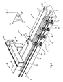
- FIG. 1 With reference to Figure 1 there is shown a machine tool 1 arranged for machining elongated elements 2, made of wood or similar materials, extending prevalently along a first longitudinal direction X.
- the elongated elements 2 for example parallelpipedon-shaped, can be grouped in groups of free elements, and, after suitable machinings, can be subsequently used as uprights or crosspieces in window frames, doors or the like.
- the machine tool 1 is arranged for performing on the elongated elements 2 machinings such as, for example, cutting, tenoning, drilling and milling.
- the machine tool 1 comprises a base 3 extending prevalently along the aforesaid first direction X.
- a loading station 4 in which the elongated elements 2 are loaded on the machine tool 1, and a first working station 5, in which the elongated elements 2 are machined.
- the first working station 5 further comprises an unloading zone 6 in which the elongated elements 2 are unloaded from the machine tool 1.
- the base 3 supports, substantially at the loading station 4, a drawing near element 7, extending along the first direction X, for example of pneumatic type.
- the drawing near element 7 is arranged for receiving and moving the elongated elements 2 on the machine tool 1 and is movable along a second transverse direction Y that is substantially perpendicular with respect to the first direction X, between a first loading position G (represented by a broken line) in which the elongated elements 2 are loaded onto a loading belt 8 and a first unloading position H in which the elongated elements 2 are unloaded from the loading belt 8 ( Figure 4).
- the loading belt 8 extends along the first direction X and is arranged for advancing the elongated elements 2 along a direction substantially parallel to the aforesaid first direction X.
- the loading belt 8 further comprises an end 9 provided with a first abutment 10, extending along the second direction Y, used as an abutment during a loading step for loading the elongated elements 2.
- the drawing near element 7 further comprises a pusher 11, having a substantially trapezoidal shape, extending along the first direction X, arranged for pushing transversely the elements 2 along the aforesaid second direction Y.
- the pusher 11 is movable with respect to the loading belt 8 towards and away from a clamping and movement device 12 arranged for receiving, retaining and moving the elongated elements 2.
- the device 12 is movable along the first direction X by means of sliding blocks 13 that are slidable along guides 14 obtained in a side surface 15 of the base 3.
- the device 12 is movable between a first operating position A (represented by a broken line), in which the device 12 is positioned substantially at the aforesaid loading station 4 and faces the drawing near element 7, and a second operating position B, in which the device 12 is positioned substantially at the aforesaid first working station 5 ( Figure 4).
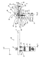
- the device 12 comprises a plurality of clamps 16, for example four in number, arranged in such a way as to define a row along the aforesaid first direction X, shown in detail in Figures 2 and 3.
- Each clamp 16 comprises a frame 19, extending along a third substantially vertical direction Z, provided with a first face 20 on which are positioned the aforesaid sliding blocks 13 and a second face 21, opposite the aforesaid first face 20, on which further guides 22 are positioned.
- the further guides 22 are slidingly associated with a sliding block element 23.
- the sliding block element 23 is associated with an upright element 26 of a first upper jaw 17 with which the clamp 16 is provided.
- the first jaw 17, extending substantially parallel to the second direction Y, has substantially the shape of an upturned "L” and is provided with a first active surface 24 arranged for contacting an upper transverse portion 25 of the elongated elements 2.
- a second lower jaw 18 extending substantially parallel to the second direction Y, provided with a second active surface 27, facing the first active surface 24, arranged for contacting a further lower transverse portion 28 of the elongated elements 2.
- the second active surface 27 comprises an end zone 30 provided with a second abutment 29 used as an abutment during a transferring step of the elongated elements 2 from the drawing near element 7 to the device 12, as will be disclosed better below.
- the first jaw 17 and the second jaw 18 face one another in such a way that, in a plan view, the first jaw 17 and the second jaw 18 substantially occupy the same overall dimensions.
- first jaw 17 is movable, through an actuator 31 (for example pneumatic), substantially parallel to the third direction Z, between a clamping position and a resting position D ( Figure 2), in which respectively the active surface 24 presses, and does not press, onto the transverse portion 25 of the elongated elements 2.
- actuator 31 for example pneumatic
- Each clamp 16 further comprises an ejecting element 33 positioned between the first jaw 17 and the second jaw 18, extending substantially along the second direction Y, provided with a pad 43.
- the pad 43 is moved by a further actuator 44, for example pneumatic, along the second direction Y and is arranged for contacting a vertical portion 34 of the elongated elements 2.
- Each clamp 16 further comprises a pair of arresting teeth 35 positioned in a further end zone 90, opposite the aforesaid end zone 30 substantially laterally with respect to the second jaw 18, arranged for contacting a further vertical portion 37 of the elongated elements 2, opposite the vertical portion 34, to lock the elongated elements 2 transversely.
- the arresting teeth 35 are movable between a further clamping position (not shown) and a further resting position E ( Figures 2 and 3), in which the arresting teeth 35 are respectively in contact and not in contact with the further vertical portion 37.
- the arresting teeth 35 are moved between the further resting position E and the further clamping position through another actuator 36, for example pneumatic.
- Each clamp 16 is further moved along a direction substantially parallel to the first direction X through motor means 32.
- each clamp 16 is movable along the axis X in an independent manner from one another.
- the machine tool 1 further comprises a first portal 40 positioned in the first working station 5 ( Figure 1).
- the first portal 40 is movable along the base 3 along the first direction X and supports a working unit 46, shown in Figure 4, movable along the first direction X, the second direction Y and the third direction Z, arranged for machining the elongated elements 2.
- the working unit 46 may comprise an electric spindle with which operating heads can be associated, for example milling units, facing tools, tenoning tools, drilling tools, etc, arranged for enabling the desired machinings to be performed.
- the machine tool 1 is further provided with an unloading belt 41 positioned in the first working station 5 that is longitudinally advanced with respect to the drawing near element 7.
- the unloading belt 41 extends along the first direction X and is arranged for receiving and subsequently advancing the elongated elements 2 in a direction substantially parallel to the aforesaid first direction X towards the unloading zone 6, in such a way as to unload the elongated elements from the machine tool 1.
- the unloading belt 41 is further movable along the second direction Y between a second loading position I (represented by a broken line) in which the unloading belt 41 receives the elongated elements 2 from the device 12, and a second unloading position L in which the unloading belt 41 unloads the aforesaid elongated elements 2 from the machine tool 1, which are shown in Figure 4.
- the elongated elements 2 for example in groups of three elements mutually drawn near along the first direction X, are arranged on the drawing near element 7 positioned in the first loading position G.
- the elongated elements 2 are positioned on the loading belt 8, which advances the elongated elements 2 along the first direction X until an end portion 42 of the elongated elements 2 abuts on the first abutment 10.
- the loading belt 8 stops and the drawing near element 7 is positioned in the first unloading position H approaching the device 12 positioned in the first operating position A.
- the arresting teeth 35 are positioned in the further resting position E and the first jaw 17 of each clamp 16 is positioned in the resting position D, in such a way as to be suitable for receiving the elongated elements 2.
- the pusher 11 pushes the elongated elements 2 towards the device 12, until a first longitudinal side 45 of a first elongated element 44 of the aforesaid elongated elements 2 abuts on the second abutment 29.
- the arresting teeth 35 are positioned in the further clamping position to lock the elongated elements 2 transversally.
- first jaws 17 are positioned in the clamping position in such a way as to lock the elongated elements 2 transversely and longitudinally.
- the device 12 is positioned in the second operating position B in such a way that the working unit 46 can perform the desired machinings, the drawing near element 7 is repositioned in the first loading position G, whilst the unloading belt 41 is positioned in the second unloading position L.
- the unloading belt 41 is positioned in the second loading position approaching the device 12 to receive the elongated elements 2.
- the first jaws 17 are repositioned in the resting position D, the arresting teeth 35 are positioned in the further resting position E and the ejecting elements 33 of the clamps 16 are driven that push the elongated elements 2 onto the unloading belt 41 along the second direction Y.
- the unloading belt 41 is positioned in the second unloading position L and is driven to make the elongated elements 2 slide to the unloading zone 6.
- a second group of elongated elements can be loaded onto the loading belt 8 in "masked time".
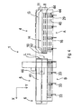
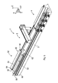
- a machine tool 1' which differs from the machine tool 1 shown in Figure 1, inasmuch as the machine tool 1' is devoid of the unloading belt 41 and of the unloading zone 6 and is provided with a second working station 50 that is longitudinally advanced with respect to the first working station 5 along the base 3, arranged for performing, for example, a profiling on the elongated elements 2.
- the second working station 50 is provided with first retaining means 52 and with second retaining means 53 extending along the first direction X, arranged for receiving, retaining and moving the elongated elements 2.
- the first retaining means 52 is movable along the first direction X between a third loading position M (represented by a broken line) and a third unloading position N, in which the first retaining means 52 are respectively positioned in the first working station 5 and in the second working station 50.
- the first retaining means 52 in the third loading position M, is substantially opposite and coplanar with the device 12, whilst in the third unloading position N, the first retaining means 52 is substantially opposite and coplanar with the second retaining means 53.
- the first retaining means 52 is movable along the second direction Y, when positioned in the third loading position M, between a first transverse position R and a second transverse position S, for receiving from the device 12, as will be better disclosed below, the elongated elements 2.
- the first retaining means 52 is movable along the second direction Y, even when in the third unloading position N, towards and away from the second retaining means 53 to enable the elongated elements 2 to be machined by the working unit 46 and to be transferred to the second transferring means 53.
- the first retaining means 52 comprises a clamping element 51 arranged for clamping the elongated elements 2.
- the clamping element 51 comprises a first upper wall 54 and a second lower wall 55 that are opposite one another and substantially parallel, extending longitudinally and substantially parallel to a plane XY.
- the first wall 54 and the second wall 55 are moved along the third direction Z between a clamping position and a releasing position, that are not shown, in which the first wall 54 and the second wall 55 respectively clamp and release the elongated elements 2, through actuating means, for example pneumatic actuating means, that are not shown.
- actuating means for example pneumatic actuating means
- the clamping element 51 is further movable along the second direction Y with respect to an abutting element 56 of the first retaining means 52.
- the abutting element 56 extending longitudinally and interposed between the first wall 54 and the second wall 55, can be moved along the second direction Y with respect to the clamping element 51.
- the second retaining means 53 comprises a further clamping element 59 arranged for clamping the elongated elements 2.
- the further clamping element 59 comprises a third upper wall 57 and a fourth lower wall 58 that are opposite one another and are substantially parallel, extending longitudinally and substantially parallel to a plane XY.
- the third wall 57 and the fourth wall 58 are moved along the third direction Z between a further clamping position and a further releasing position, which are not shown, in which respectively the third wall 57 and the fourth wall 58 clamp and release the elongated elements 2, through further actuating means, for example pneumatic actuating means, which are not shown.
- the third wall 57 and the fourth wall 58 comprise respective end portions comprising respectively an active portion 60 and a further active portion 61, facing one another, arranged for contacting the elongated elements 2 during a clamping step.
- the fourth wall 58 further comprises a further unloading belt 62, adjacent to and substantially coplanar with the further active portion 61, and positioned downstream of the latter, with respect to the second direction Y.
- the further unloading belt 62 extends longitudinally and is arranged for advancing, at the end of machining, the elongated elements 2 along the first direction X to a further unloading zone 63 and then evacuating the latter from the machine tool 1', as disclosed below.
- the first wall 54, the second wall 55, the active portion 60 and the further active portion 61 can provide an irregular profile 64, for example serrated, to encourage the clamping of the elongated elements 2.
- the working unit 46 has performed the desired operations on the elongated elements 2, for example machinings such as cutting, tenoning, drilling, milling in the first working station 5, the elongated elements 2 can be transferred from the device 12 to the first retaining means 52.
- the first retaining means 52 is positioned in the third loading position M and in the first transverse position R, with the first wall 54 and the second wall 55 positioned in the releasing position, in such a way as to be able to receive the elongated elements 2.
- the first jaws 17 of the device 12 are positioned in the resting position D, the arresting teeth 35 are positioned in the further resting position E and the ejecting elements 33 of the clamps 16 are driven that push the elongated elements 2 to the first retaining means 52 until the elongated elements 2 abut on the abutting element 56.
- first wall 54 and the second wall 55 are positioned in the clamping position to clamp the elongated elements 2, and still subsequently the first retaining means 52 is positioned in the second transverse position S.
- the device 12 is repositioned in the first operating position A to receive further elongated elements to be machined.
- the first clamping means 52 is positioned in the third unloading position N, and the first portal 40 is positioned in the second working station 50.
- the machine tool 1' is provided with a first portal arranged for machining the elongated elements in the first working station 5 and of a second portal arranged for machining the elongated elements in the second working station 50, in such a way as to significantly increase the productive capacity of the machine tool 1'.
- the working unit 46 can machine the first longitudinal side 45 of the first elongated element 44, the first elongated element 44 being retained by the clamping element 51 in such a way that the first elongated element 44 protrudes from the latter by a certain amount AA along the second direction Y ( Figure 7a).
- the first retaining means 52 approaches the second retaining means 53 in such a way that the first elongated element 44 is received, at least partially, between the active portion 60 and the further active portion 61 positioned in the further release position.
- the active portion 60 and the further active portion 61 are positioned in the still further clamping position and still subsequently the first wall 54 and the second wall 55 are positioned in the releasing position.
- the abutting element 56 Whilst the clamping element 51 moves away from the aforesaid second retaining means 53, the abutting element 56 remains fixed with respect to the latter in such a way that a second elongated element 70 of said elongated elements 2 protrudes from the clamping element 51 substantially by that certain amount AA.
- first wall 54 and the second wall 55 are positioned in the clamping position.
- the working unit 46 can machine a second longitudinal side 71 of the first elongated element 44 opposite and substantially parallel to the first longitudinal side 45, and a third longitudinal side 72 of the second elongated element 70 facing the second longitudinal side 71.
- the working unit 46 can substantially perform at the same time the required machinings on the second longitudinal side 71 and on the third longitudinal side 72.
- the first transferring means 52 is moved again to the second retaining means 53 ( Figure 7e) in such a way that the second elongated element 70 is positioned almost in contact with the first elongated element 44.
- the active portion 60 and the further active portion 61 are positioned in the further releasing position and the first retaining means 52 are moved nearer the second retaining means 53 ( Figure 7f), in such a way that the first elongated element 44 is pushed by the second elongated element 70 on the further unloading belt 62.
- the active portion 60 and the further active portion 61 are positioned in the further clamping position, after which the further unloading belt 62 evacuates the first elongated element 44 from the machine tool 1'.
- the abutting element 56 Whilst the clamping element 51 moves away from the aforesaid second retaining means 53, the abutting element 56 remains fixed in respect to the latter in such a way that a third elongated element 73 of said elongated elements 2 protrudes from the clamping element 51 substantially by that certain amount AA.
- first wall 54 and the second wall 55 are positioned in the clamping position.
- the working unit 46 can machine a fourth longitudinal side 74 of the second elongated element 70 opposite and substantially parallel to the third longitudinal side 72, and a fifth longitudinal side 75 of the third elongated element 73 facing the fourth longitudinal side 74.
- the working unit 46 can substantially perform at the same time the required machinings on the fourth longitudinal side 74 and on the fifth longitudinal side 75.
- the first retaining means 52 again approaches the second retaining means 53 ( Figure 7i), in such a way that the third elongated element 73 is positioned almost in contact with the second elongated element 70.
- the active portion 60 and the further active portion 61 are positioned in the further releasing position and the first retaining means 52 are moved nearer the second retaining means 53 ( Figure 71), in such a way that the second elongated element 70 is pushed by the third elongated element 73 onto the further unloading belt 62.
- the active portion 60 and the further active portion 61 are positioned in the further clamping position, after which the further unloading belt 62 evacuates the second elongated element 70 from the machine tool 1'.
- first wall 54 and the second wall 55 are positioned in the releasing position and the first retaining means 52, devoid of elongated elements 2, moves away from the second retaining means 53, in the third unloading position N ( Figure 7m), and the abutting element 56 is moved along the second direction Y with respect to the clamping element 51, in such a way that the second retaining means 52 is suitable for receiving further elongated elements 2'.
- the working unit 46 can machine a sixth longitudinal side 77 of the third elongated element 73 opposite and substantially parallel to the fifth longitudinal side 75.
- two situations may occur: a first case in which during machining of the sixth longitudinal side 77 the further elongated elements 2' are loaded in "masked time" and a second case in which the first retaining means 52 are not loaded with further elongated elements 2'.
- the third elongated element 73 is positioned on the further unloading belt 56 by a fourth elongated element 76, in a similar manner to what has been said previously for the first elongated element 44 and the second elongated element 70.
- the abutting element 56 interacts with the sixth longitudinal side 77 and pushes the third elongated element 73 onto the further unloading belt 62, which evacuates the third elongated element 73 from the machine tool 1'.
- an elongated element passes from the first retaining means 52 to the second retaining means 53, always with the elongated element locked, which entails good movement precision.
- a machine tool 1" which differs from the machine tool 1 shown in Figure 1, inasmuch as the machine tool 1" is provided with a multifunctional plane 80, extending along the first direction X and supported by the base 3, positioned in the first working station 5.
- the machine tool 1" is arranged for performing, for example, cutting, tenoning, drilling, milling, profiling, rabetting and pantograph machinings on the elongated elements 2.
- the multifunctional plane 80 comprises a plurality of bars 81 extending substantially parallel to the second direction Y and adjustable parallel to the first direction X.
- the bars 81 are arranged for supporting the elongated elements 2, which can be handled and positioned manually by an operator.
- Each bar 81 can be provided with gripping elements 82 arranged for retaining the elongated elements 2 during the aforesaid machinings, comprising for example suction cups or clamps.
- the elongated elements 2 are evacuated from the machine tool 1" through a still further unloading belt 83.
- the multifunctional plane 80 may not be supported by the base 3 and may be positioned substantially parallel to the latter.
- the multifunctional plane 80 can be associated with the machine tool in one of the manners disclosed above.
Landscapes
- Life Sciences & Earth Sciences (AREA)
- Engineering & Computer Science (AREA)
- Wood Science & Technology (AREA)
- Mechanical Engineering (AREA)
- Forests & Forestry (AREA)
- Finish Polishing, Edge Sharpening, And Grinding By Specific Grinding Devices (AREA)
- Jigs For Machine Tools (AREA)
Abstract
Description
- The invention relates to a machine tool, in particular a machine tool arranged for machining elongated elements, such as, for example, workpieces made of wood or similar materials.
- Such elongated elements comprises parallelpipedon-shaped elements intended for being used as uprights and crosspieces in frames of windows, doors or the like.
- The invention further relates to a method for machining such elongated elements.
- The minimum operations provided for making an elongated element into a semifinished product and then into a finished product may comprise machinings performed on front end portions of the aforesaid elongated element, said also "front-end" machinings, such as for example cutting and/or tenoning, and operations performed along a longitudinal development of the aforesaid elongated element, for example profiling and/or slotting and/or drilling.
-
EP 1281491 teaches a machine for machining elongated elements extending longitudinally made of wood, plastics, or similar materials, having a profiling unit provided with at least a spindle arranged for performing longitudinal profiling of the aforesaid workpieces. - This machine is further provided with an advancing unit arranged for moving an elongated element to the profiling unit along a longitudinal advancing direction.
- The advancing unit comprises upper clamping jaws arranged above the elongated element and lower clamping jaws arranged below the elongated element, cooperating together to clamp the elongated element during an advancing step and a machining step.
- The upper clamping jaws and the lower clamping jaws are positioned on the advancing unit in such a way that, in a plan view, the upper clamping jaws are staggered with respect to the lower clamping jaws.
- In particular, the upper clamping jaws and the lower clamping jaws, in a plan view, have a profile with a complementary shape.
- The aforesaid upper and lower clamping jaws are further arranged in a row on the aforesaid advancing unit along the longitudinal advancing direction.
- A drawback of the machines made according to
EP 1281491 consists of the presence of a clamping zone, extending prevalently longitudinally, in which it is not possible to machine the elongated element. - This is due to the fact that in this clamping zone the elongated element is clamped between the upper clamping jaws and the lower clamping jaws.
- As a result, in order to machine such a clamping zone, it is necessary to provide a further advancing unit, opposite the aforesaid advancing unit and movable along the aforesaid longitudinal advancing direction.
- The further advancing unit removes the elongated elements first clamped in the advancing unit, clamps this elongated elements between further jaws in a further clamping zone, opposite the aforesaid clamping zone, and advances this elongated elements to a further profiling unit that is longitudinally advanced with respect to the aforesaid profiling unit, arranged for machining the elongated elements in the clamping zone that had already been clamped between the upper clamping jaws and the lower clamping jaws. It is obvious that the addition of a further advancing unit entails an increase in the costs to be sustained to make such a machine and increases the overall dimensions thereof. A further drawback of the machines made according to
EP 1281491 consists of the possibility of machining only one elongated element a time, with consequent reduced machine productive capacity.
A still further drawback relates to the constructional complexity of the known machines. - An object of the invention is to improve the machine tools arranged for machining elongated elements made of wood or similar materials.
- A further object is to make machine tools that enable productive capacity to be increased with respect to known machine tools.
- A still further object is to make machine tools that are cheap and easy to make.
- A further object is to make machine tools with limited overall dimensions.
- A further object is to improve the machining methods for machining elongated elements.
- In a first aspect of the invention, there is provided a machine tool for machining elongated elements made of wood or similar materials, comprising retaining means arranged for clamping and moving said elongated elements along a first longitudinal direction and provided with a plurality of clamps, each clamp comprising clamping elements arranged for clamping said elongated elements therebetween, characterised in that said clamping elements, in a plan view, substantially occupy the same overall dimensions.
- Owing to the first aspect of the invention it is possible to increase the productive capacity of the machine tool significantly.
- In fact, the retaining means may for example comprise four clamps that are equidistant from one another and movable along the aforesaid first longitudinal direction.
- Each clamp is then provided with a pair of jaws facing one another and extending along a second direction, that is transverse with respect to the first direction.
- This enables a plurality of elongated elements to be moved simultaneously, for example in groups of three at a time.
- Further, the shape of the jaws, and in particular the reduced extent along the first longitudinal direction, and the mutual distance between two consecutive clamps, enables a clamping zone to be greatly reduced that is required for clamping the elongated elements and correspondingly increasing a free surface of the elongated elements that it is possible to machine.
- This enables the machine to be simplified significantly, which no longer requires movement devices, with consequent containment of costs and reduction of overall dimensions.
- In a second aspect of the invention, there is provided a machine tool for machining elongated elements made of wood or similar materials, comprising retaining means arranged for clamping and moving said elongated elements along a first longitudinal direction comprising at least a clamp comprising clamping elements arranged for clamping said elongated elements therebetween, characterised in that it further comprises an abutting element movable along a second direction, that is transverse to said first direction, with respect to said clamping elements.
- In an embodiment of the invention the retaining means comprises an active portion arranged for clamping an elongated element to be machined and a further portion, adjacent to the active portion, provided with an unloading belt arranged for unloading an elongated element that has already been machined.
- In a third aspect of the invention, there is provided a method for machining elongated elements made of wood or similar materials defining a first longitudinal direction, comprising retaining said elongated elements in a clamping element of first retaining means in such a way that a first elongated element of said elongated elements protrudes along a second direction, that is transverse to said first direction, by a certain amount from said clamping element, approaching along said second direction said first retaining means to second retaining means suitable for receiving and retaining said elongated elements, releasing said clamping element, moving away along said second direction said clamping element from said second retaining means by a further certain amount, characterised in that said moving away comprises maintaining an abutting element of said first retaining means locked along said second direction in such a way that a second elongated element of said elongated elements protrudes from said clamping element substantially by said certain amount.
- Owing to the second and the third aspect of the invention it is possible to increase further the productive capacity of the machine tool.
- In fact, it is possible to machine simultaneously two elongated elements by transferring a partially machined elongated element from the first retaining means to the second retaining means.
- In fact, for example if the elongated elements are in groups of three elements, it is possible to transfer a first elongated element from the first retaining means to the second retaining means, machining a face of the first elongated element whilst the first elongated element is clamped in the active portion of the second retaining means and simultaneously machine also a second face opposite the first face of a second elongated element whilst the second elongated element is clamped by the first retaining means.
- Subsequently, it is possible to unload through the unloading belt the first elongated element from the machine, whilst the second elongated element retained by the aforesaid active portion and a third element retained by the first clamping means are machined simultaneously.
- The invention can be better understood and carried into effect with reference to the attached drawings in which some embodiments of the invention are shown by way of nonlimiting example, in which:
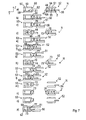
- Figure 1 is an axonometric view of a machine tool arranged for machining elongated elements;
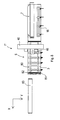
- Figure 2 is a side view of a detail of the machine in Figure 1;
- Figure 3 is a rear view of the detail in Figure 3;
- Figure 4 is a plan view of the machine tool in Figure 1 that illustrates a possible operating sequence thereof;
- Figure 5 is an axonometric view of an alternative embodiment of the machine in Figure 1;
- Figure 6 is a plan view of the machine tool in Figure 5 that illustrates a possible operating sequence thereof;
- Figure 6a is an enlarged detail of Figure 6;
- Figure 7 illustrates a possible operating sequence of the machine in Figure 5;
- Figure 8 is an axonometric view of a further alternative embodiment of the machine in Figure 1.
- With reference to Figure 1 there is shown a
machine tool 1 arranged for machiningelongated elements 2, made of wood or similar materials, extending prevalently along a first longitudinal direction X. - The
elongated elements 2, for example parallelpipedon-shaped, can be grouped in groups of free elements, and, after suitable machinings, can be subsequently used as uprights or crosspieces in window frames, doors or the like. Themachine tool 1 is arranged for performing on theelongated elements 2 machinings such as, for example, cutting, tenoning, drilling and milling. - The
machine tool 1 comprises abase 3 extending prevalently along the aforesaid first direction X. - Along the
base 3 there are defined aloading station 4, in which theelongated elements 2 are loaded on themachine tool 1, and afirst working station 5, in which theelongated elements 2 are machined. - The
first working station 5 further comprises an unloading zone 6 in which theelongated elements 2 are unloaded from themachine tool 1. - The
base 3 supports, substantially at theloading station 4, a drawing nearelement 7, extending along the first direction X, for example of pneumatic type. - The drawing near
element 7 is arranged for receiving and moving theelongated elements 2 on themachine tool 1 and is movable along a second transverse direction Y that is substantially perpendicular with respect to the first direction X, between a first loading position G (represented by a broken line) in which theelongated elements 2 are loaded onto aloading belt 8 and a first unloading position H in which theelongated elements 2 are unloaded from the loading belt 8 (Figure 4). - The
loading belt 8 extends along the first direction X and is arranged for advancing theelongated elements 2 along a direction substantially parallel to the aforesaid first direction X. - The
loading belt 8 further comprises anend 9 provided with afirst abutment 10, extending along the second direction Y, used as an abutment during a loading step for loading theelongated elements 2. - The drawing near
element 7 further comprises a pusher 11, having a substantially trapezoidal shape, extending along the first direction X, arranged for pushing transversely theelements 2 along the aforesaid second direction Y. - In fact, the pusher 11 is movable with respect to the
loading belt 8 towards and away from a clamping andmovement device 12 arranged for receiving, retaining and moving theelongated elements 2. - The
device 12 is movable along the first direction X by means of slidingblocks 13 that are slidable alongguides 14 obtained in aside surface 15 of thebase 3. - In particular, the
device 12 is movable between a first operating position A (represented by a broken line), in which thedevice 12 is positioned substantially at theaforesaid loading station 4 and faces the drawing nearelement 7, and a second operating position B, in which thedevice 12 is positioned substantially at the aforesaid first working station 5 (Figure 4). - The
device 12 comprises a plurality ofclamps 16, for example four in number, arranged in such a way as to define a row along the aforesaid first direction X, shown in detail in Figures 2 and 3. - Each
clamp 16 comprises aframe 19, extending along a third substantially vertical direction Z, provided with afirst face 20 on which are positioned the aforesaidsliding blocks 13 and asecond face 21, opposite the aforesaidfirst face 20, on whichfurther guides 22 are positioned. - The
further guides 22 are slidingly associated with a slidingblock element 23. - The sliding
block element 23 is associated with anupright element 26 of a firstupper jaw 17 with which theclamp 16 is provided. - The
first jaw 17, extending substantially parallel to the second direction Y, has substantially the shape of an upturned "L" and is provided with a firstactive surface 24 arranged for contacting an uppertransverse portion 25 of theelongated elements 2. - With the
frame 19 there is further associated a secondlower jaw 18, extending substantially parallel to the second direction Y, provided with a secondactive surface 27, facing the firstactive surface 24, arranged for contacting a further lowertransverse portion 28 of theelongated elements 2. - Further, the second
active surface 27 comprises anend zone 30 provided with asecond abutment 29 used as an abutment during a transferring step of theelongated elements 2 from the drawing nearelement 7 to thedevice 12, as will be disclosed better below. - The
first jaw 17 and thesecond jaw 18 face one another in such a way that, in a plan view, thefirst jaw 17 and thesecond jaw 18 substantially occupy the same overall dimensions. - Further, the
first jaw 17 is movable, through an actuator 31 (for example pneumatic), substantially parallel to the third direction Z, between a clamping position and a resting position D (Figure 2), in which respectively theactive surface 24 presses, and does not press, onto thetransverse portion 25 of theelongated elements 2. - Each
clamp 16 further comprises an ejectingelement 33 positioned between thefirst jaw 17 and thesecond jaw 18, extending substantially along the second direction Y, provided with apad 43. - The
pad 43 is moved by afurther actuator 44, for example pneumatic, along the second direction Y and is arranged for contacting avertical portion 34 of theelongated elements 2. - Each
clamp 16 further comprises a pair of arrestingteeth 35 positioned in afurther end zone 90, opposite theaforesaid end zone 30 substantially laterally with respect to thesecond jaw 18, arranged for contacting a furthervertical portion 37 of theelongated elements 2, opposite thevertical portion 34, to lock theelongated elements 2 transversely. - In particular, the arresting
teeth 35 are movable between a further clamping position (not shown) and a further resting position E (Figures 2 and 3), in which the arrestingteeth 35 are respectively in contact and not in contact with the furthervertical portion 37. - The arresting
teeth 35 are moved between the further resting position E and the further clamping position through anotheractuator 36, for example pneumatic. - Each
clamp 16 is further moved along a direction substantially parallel to the first direction X through motor means 32. - In an embodiment of the invention, each
clamp 16 is movable along the axis X in an independent manner from one another. - The
machine tool 1 further comprises afirst portal 40 positioned in the first working station 5 (Figure 1). - The
first portal 40 is movable along thebase 3 along the first direction X and supports a workingunit 46, shown in Figure 4, movable along the first direction X, the second direction Y and the third direction Z, arranged for machining theelongated elements 2. - The working
unit 46 may comprise an electric spindle with which operating heads can be associated, for example milling units, facing tools, tenoning tools, drilling tools, etc, arranged for enabling the desired machinings to be performed. - In an embodiment of the invention, not shown, it is possible to provide several portals and several tool units, according to the number of machinings to be performed and the time required to perform such machinings.
- The
machine tool 1 is further provided with an unloadingbelt 41 positioned in the first workingstation 5 that is longitudinally advanced with respect to the drawing nearelement 7. - The unloading
belt 41 extends along the first direction X and is arranged for receiving and subsequently advancing theelongated elements 2 in a direction substantially parallel to the aforesaid first direction X towards the unloading zone 6, in such a way as to unload the elongated elements from themachine tool 1. - The unloading
belt 41 is further movable along the second direction Y between a second loading position I (represented by a broken line) in which the unloadingbelt 41 receives theelongated elements 2 from thedevice 12, and a second unloading position L in which the unloadingbelt 41 unloads the aforesaidelongated elements 2 from themachine tool 1, which are shown in Figure 4. - The operation of the
machine tool 1 is disclosed below with particular reference to Figure 4. - In the initial loading step, the
elongated elements 2, for example in groups of three elements mutually drawn near along the first direction X, are arranged on the drawing nearelement 7 positioned in the first loading position G. - In particular, the
elongated elements 2 are positioned on theloading belt 8, which advances theelongated elements 2 along the first direction X until anend portion 42 of theelongated elements 2 abuts on thefirst abutment 10. - Subsequently, the
loading belt 8 stops and the drawing nearelement 7 is positioned in the first unloading position H approaching thedevice 12 positioned in the first operating position A. - In turn, the arresting
teeth 35 are positioned in the further resting position E and thefirst jaw 17 of eachclamp 16 is positioned in the resting position D, in such a way as to be suitable for receiving theelongated elements 2. - Subsequently, the pusher 11 is driven towards the
device 12. - In this way, the pusher 11 pushes the
elongated elements 2 towards thedevice 12, until a firstlongitudinal side 45 of a firstelongated element 44 of the aforesaidelongated elements 2 abuts on thesecond abutment 29. - Still subsequently, the arresting
teeth 35 are positioned in the further clamping position to lock theelongated elements 2 transversally. - Still subsequently, the
first jaws 17 are positioned in the clamping position in such a way as to lock theelongated elements 2 transversely and longitudinally. - At this point, the
device 12 is positioned in the second operating position B in such a way that the workingunit 46 can perform the desired machinings, the drawing nearelement 7 is repositioned in the first loading position G, whilst the unloadingbelt 41 is positioned in the second unloading position L. - Once the desired machinings have been performed by the working
unit 46, the unloadingbelt 41 is positioned in the second loading position approaching thedevice 12 to receive theelongated elements 2. - The
first jaws 17 are repositioned in the resting position D, the arrestingteeth 35 are positioned in the further resting position E and the ejectingelements 33 of theclamps 16 are driven that push theelongated elements 2 onto the unloadingbelt 41 along the second direction Y. - Still subsequently, the unloading
belt 41 is positioned in the second unloading position L and is driven to make theelongated elements 2 slide to the unloading zone 6. - It should be noted that during machining of a first unit of elongated elements, a second group of elongated elements can be loaded onto the
loading belt 8 in "masked time". - In an alternative embodiment, shown in Figures 6, 6a and 7, there is provided a machine tool 1', which differs from the
machine tool 1 shown in Figure 1, inasmuch as the machine tool 1' is devoid of the unloadingbelt 41 and of the unloading zone 6 and is provided with a second workingstation 50 that is longitudinally advanced with respect to the first workingstation 5 along thebase 3, arranged for performing, for example, a profiling on theelongated elements 2. - The second working
station 50 is provided with first retaining means 52 and with second retaining means 53 extending along the first direction X, arranged for receiving, retaining and moving theelongated elements 2. - The first retaining means 52 is movable along the first direction X between a third loading position M (represented by a broken line) and a third unloading position N, in which the first retaining means 52 are respectively positioned in the first working
station 5 and in the second workingstation 50. - In particular, in the third loading position M, the first retaining means 52 is substantially opposite and coplanar with the
device 12, whilst in the third unloading position N, the first retaining means 52 is substantially opposite and coplanar with the second retaining means 53. - In particular, the first retaining means 52 is movable along the second direction Y, when positioned in the third loading position M, between a first transverse position R and a second transverse position S, for receiving from the
device 12, as will be better disclosed below, theelongated elements 2. - On the other hand the first retaining means 52 is movable along the second direction Y, even when in the third unloading position N, towards and away from the second retaining means 53 to enable the
elongated elements 2 to be machined by the workingunit 46 and to be transferred to the second transferring means 53. - The first retaining means 52 comprises a clamping
element 51 arranged for clamping theelongated elements 2. - The clamping
element 51 comprises a firstupper wall 54 and a secondlower wall 55 that are opposite one another and substantially parallel, extending longitudinally and substantially parallel to a plane XY. - The
first wall 54 and thesecond wall 55 are moved along the third direction Z between a clamping position and a releasing position, that are not shown, in which thefirst wall 54 and thesecond wall 55 respectively clamp and release theelongated elements 2, through actuating means, for example pneumatic actuating means, that are not shown. - This also enables the grip of the
elongated elements 2 to be adjusted according to the thickness thereof. - The clamping
element 51 is further movable along the second direction Y with respect to anabutting element 56 of the first retaining means 52. - Also the abutting
element 56, extending longitudinally and interposed between thefirst wall 54 and thesecond wall 55, can be moved along the second direction Y with respect to the clampingelement 51. - The second retaining means 53 comprises a
further clamping element 59 arranged for clamping theelongated elements 2. - The
further clamping element 59 comprises a thirdupper wall 57 and a fourthlower wall 58 that are opposite one another and are substantially parallel, extending longitudinally and substantially parallel to a plane XY. - The
third wall 57 and thefourth wall 58 are moved along the third direction Z between a further clamping position and a further releasing position, which are not shown, in which respectively thethird wall 57 and thefourth wall 58 clamp and release theelongated elements 2, through further actuating means, for example pneumatic actuating means, which are not shown. - The
third wall 57 and thefourth wall 58 comprise respective end portions comprising respectively anactive portion 60 and a further active portion 61, facing one another, arranged for contacting theelongated elements 2 during a clamping step. - The
fourth wall 58 further comprises afurther unloading belt 62, adjacent to and substantially coplanar with the further active portion 61, and positioned downstream of the latter, with respect to the second direction Y. - The
further unloading belt 62 extends longitudinally and is arranged for advancing, at the end of machining, theelongated elements 2 along the first direction X to afurther unloading zone 63 and then evacuating the latter from the machine tool 1', as disclosed below. - As shown in Figure 6a, the
first wall 54, thesecond wall 55, theactive portion 60 and the further active portion 61 can provide anirregular profile 64, for example serrated, to encourage the clamping of theelongated elements 2. - The operation of the machine tool 1' is disclosed below with particular reference to Figures 6 and 7.
- This operation is taught from the first working
station 5, inasmuch as the operations conducted upstream of the latter, precisely in theloading station 4, have already been disclosed previously with reference tomachine tool 1. - Once the working
unit 46 has performed the desired operations on theelongated elements 2, for example machinings such as cutting, tenoning, drilling, milling in the first workingstation 5, theelongated elements 2 can be transferred from thedevice 12 to the first retaining means 52. - In order to do so, the first retaining means 52 is positioned in the third loading position M and in the first transverse position R, with the
first wall 54 and thesecond wall 55 positioned in the releasing position, in such a way as to be able to receive theelongated elements 2. - The
first jaws 17 of thedevice 12 are positioned in the resting position D, the arrestingteeth 35 are positioned in the further resting position E and the ejectingelements 33 of theclamps 16 are driven that push theelongated elements 2 to the first retaining means 52 until theelongated elements 2 abut on the abuttingelement 56. - Subsequently, the
first wall 54 and thesecond wall 55 are positioned in the clamping position to clamp theelongated elements 2, and still subsequently the first retaining means 52 is positioned in the second transverse position S. - Subsequently, the
device 12 is repositioned in the first operating position A to receive further elongated elements to be machined. - At this point, the first clamping means 52 is positioned in the third unloading position N, and the
first portal 40 is positioned in the second workingstation 50. - In an embodiment of the invention, which is not shown, the machine tool 1' is provided with a first portal arranged for machining the elongated elements in the first working
station 5 and of a second portal arranged for machining the elongated elements in the second workingstation 50, in such a way as to significantly increase the productive capacity of the machine tool 1'. - Subsequently, the working
unit 46 can machine the firstlongitudinal side 45 of the firstelongated element 44, the firstelongated element 44 being retained by the clampingelement 51 in such a way that the firstelongated element 44 protrudes from the latter by a certain amount AA along the second direction Y (Figure 7a). - Once machining has been completed on the first longitudinal side 45 (Figure 7b), for example a profiling, the first retaining means 52 approaches the second retaining means 53 in such a way that the first
elongated element 44 is received, at least partially, between theactive portion 60 and the further active portion 61 positioned in the further release position. - Subsequently, the
active portion 60 and the further active portion 61 are positioned in the still further clamping position and still subsequently thefirst wall 54 and thesecond wall 55 are positioned in the releasing position. - Subsequently (Figure 7c), the clamping
element 51 moves away from the second retaining means 53. - Whilst the clamping
element 51 moves away from the aforesaid second retaining means 53, the abuttingelement 56 remains fixed with respect to the latter in such a way that a secondelongated element 70 of saidelongated elements 2 protrudes from the clampingelement 51 substantially by that certain amount AA. - Subsequently, the
first wall 54 and thesecond wall 55 are positioned in the clamping position. - Subsequently the first retaining means 52 is repositioned in the third unloading position N (Figure 7d).
- In the third unloading position N, the working
unit 46 can machine a second longitudinal side 71 of the firstelongated element 44 opposite and substantially parallel to the firstlongitudinal side 45, and a thirdlongitudinal side 72 of the secondelongated element 70 facing the second longitudinal side 71. - In an embodiment of the invention, the working
unit 46 can substantially perform at the same time the required machinings on the second longitudinal side 71 and on the thirdlongitudinal side 72. - At the end of machining, the first transferring means 52 is moved again to the second retaining means 53 (Figure 7e) in such a way that the second
elongated element 70 is positioned almost in contact with the firstelongated element 44. - Subsequently, the
active portion 60 and the further active portion 61 are positioned in the further releasing position and the first retaining means 52 are moved nearer the second retaining means 53 (Figure 7f), in such a way that the firstelongated element 44 is pushed by the secondelongated element 70 on thefurther unloading belt 62. - Subsequently, the
active portion 60 and the further active portion 61 are positioned in the further clamping position, after which the further unloadingbelt 62 evacuates the firstelongated element 44 from the machine tool 1'. - Subsequently, the
first wall 54 and thesecond wall 55 is positioned in the releasing position and the clampingelement 51 is moved away from the second retaining means 53 (Figure 7g). - Whilst the clamping
element 51 moves away from the aforesaid second retaining means 53, the abuttingelement 56 remains fixed in respect to the latter in such a way that a thirdelongated element 73 of saidelongated elements 2 protrudes from the clampingelement 51 substantially by that certain amount AA. - Subsequently, the
first wall 54 and thesecond wall 55 are positioned in the clamping position. - Subsequently, the first retaining means 52 is repositioned in the third unloading position N (Figure 7h).
- In the third unloading position N, the working
unit 46 can machine a fourth longitudinal side 74 of the secondelongated element 70 opposite and substantially parallel to the thirdlongitudinal side 72, and a fifthlongitudinal side 75 of the thirdelongated element 73 facing the fourth longitudinal side 74. - In an embodiment of the invention, the working
unit 46 can substantially perform at the same time the required machinings on the fourth longitudinal side 74 and on the fifthlongitudinal side 75. - At the end of machining, the first retaining means 52 again approaches the second retaining means 53 (Figure 7i), in such a way that the third
elongated element 73 is positioned almost in contact with the secondelongated element 70. - Subsequently, the
active portion 60 and the further active portion 61 are positioned in the further releasing position and the first retaining means 52 are moved nearer the second retaining means 53 (Figure 71), in such a way that the secondelongated element 70 is pushed by the thirdelongated element 73 onto thefurther unloading belt 62. - Subsequently, the
active portion 60 and the further active portion 61 are positioned in the further clamping position, after which the further unloadingbelt 62 evacuates the secondelongated element 70 from the machine tool 1'. - Subsequently, the
first wall 54 and thesecond wall 55 are positioned in the releasing position and the first retaining means 52, devoid ofelongated elements 2, moves away from the second retaining means 53, in the third unloading position N (Figure 7m), and the abuttingelement 56 is moved along the second direction Y with respect to the clampingelement 51, in such a way that the second retaining means 52 is suitable for receiving further elongated elements 2'. - At this point, the working
unit 46 can machine a sixth longitudinal side 77 of the thirdelongated element 73 opposite and substantially parallel to the fifthlongitudinal side 75. - At the end of machining, in order to evacuate the third
elongated element 73, two situations may occur: a first case in which during machining of the sixth longitudinal side 77 the further elongated elements 2' are loaded in "masked time" and a second case in which the first retaining means 52 are not loaded with further elongated elements 2'. - In the first case (Figure 7n), the third
elongated element 73 is positioned on thefurther unloading belt 56 by a fourthelongated element 76, in a similar manner to what has been said previously for the firstelongated element 44 and the secondelongated element 70. - In the second case (Figures 7o and 7p), the empty first retaining means 52 approaches the second retaining means 53, in such a way that the clamping
element 51 is almost in contact with thefurther clamping element 59, after which theactive portion 60 and the further active portion 61 are positioned in the further releasing position. - Subsequently (Figure 7p), the abutting
element 56 moves towards the second retaining means 53, maintaining the clampingelement 51 fixed. - In this way, the abutting
element 56 interacts with the sixth longitudinal side 77 and pushes the thirdelongated element 73 onto thefurther unloading belt 62, which evacuates the thirdelongated element 73 from the machine tool 1'. - It should be noted that an elongated element passes from the first retaining means 52 to the second retaining means 53, always with the elongated element locked, which entails good movement precision.
- It should further be noted that an elongated element is unloaded individually in "masked time" during profiling, with a consequent increase of the productive capacity of the machine tool.
- In an alternative embodiment shown in Figure 8, there is provided a
machine tool 1" , which differs from themachine tool 1 shown in Figure 1, inasmuch as themachine tool 1" is provided with amultifunctional plane 80, extending along the first direction X and supported by thebase 3, positioned in the first workingstation 5. - The
machine tool 1" is arranged for performing, for example, cutting, tenoning, drilling, milling, profiling, rabetting and pantograph machinings on theelongated elements 2. - The
multifunctional plane 80 comprises a plurality ofbars 81 extending substantially parallel to the second direction Y and adjustable parallel to the first direction X. - The
bars 81 are arranged for supporting theelongated elements 2, which can be handled and positioned manually by an operator. - Each
bar 81 can be provided withgripping elements 82 arranged for retaining theelongated elements 2 during the aforesaid machinings, comprising for example suction cups or clamps. - Once the aforesaid machinings have been completed, the
elongated elements 2 are evacuated from themachine tool 1" through a still further unloadingbelt 83. - In an embodiment of the invention that is not shown the
multifunctional plane 80 may not be supported by thebase 3 and may be positioned substantially parallel to the latter. - In a further embodiment of the invention that is not shown, the
multifunctional plane 80 can be associated with the machine tool in one of the manners disclosed above.
Claims (80)
- Machine tool for machining elongated elements (2) made of wood or similar materials, comprising retaining means (12) arranged for clamping and moving said elongated elements (2) along a first longitudinal direction (X) and provided with a plurality of clamps (16), each clamp (16) comprising clamping elements (17, 18) arranged for clamping said elongated elements (2) therebetween, characterised in that said clamping elements (17, 18), in a plan view, substantially occupy the same overall dimensions.
- Machine according to claim 1, wherein said clamping elements (17, 18) extend along a second direction (Y) that is transverse to said first direction (X).
- Machine according to claim 1, or 2, wherein said clamping elements comprise a first jaw (17) and a second jaw (18), facing one another.
- Machine according to claim 3, wherein said first jaw (17) is movable along a third substantially vertical direction (Z) towards and away from said second jaw (18).
- Machine according to any preceding claim, wherein each of said clamps (16) comprises an ejecting element (33) that is movable along said second direction (Y) suitable for interacting with a portion (34) of said elongated elements (2).
- Machine according to claim 5, wherein said ejecting element (33) is positioned between said first jaw (17) and said second jaw (18).
- Machine according to claim 5, or 6, wherein said ejecting element (33) comprises a pneumatic actuator (44).
- Machine according to any one of claims 5 to 7, wherein each of said clamps (16) comprises an end zone (30) provided with a projecting element (29) arranged for contacting said portion (34).
- Machine according to claim 8, wherein said projecting element (29) projects from an active surface (27) of said second jaw (18) arranged for contacting said elongated elements (2).
- Machine according to claim 8, or 9, wherein each clamps (16) comprises a further end zone (90), opposite said end zone (30), provided with an arresting element (35) arranged for interacting with said projecting element (29) to lock said elongated elements (2) transversely.
- Machine according to claim 10, wherein said arresting element (35) is movable between a locking position and a releasing position for locking and releasing said elongated elements (2).
- Machine according to claim 10, or 11, wherein said arresting element comprises arresting teeth (35) arranged for interacting with a further portion (37) of said elongated elements (2), said further portion (37) being opposite said portion (34).
- Machine according to any preceding claim, wherein said plurality of clamps comprises clamps (16) associated with one another in such a way as to move together along said first direction (X) along a base (3) of said machine.
- Machine according to claim 13, wherein said base (3) supports in a loading zone (4) a drawing near element (7) extending along said first direction (X) arranged for receiving and moving said elongated elements (2).
- Machine according to claim 14, wherein said drawing near element (7) is movable along said second direction (Y) towards and away from said plurality of clamps (16).
- Machine according to claim 14, or 15, wherein said drawing near element (7) comprises a loading belt (8) arranged for advancing said elongated elements (2) along said first direction (X).
- Machine according to any one of claims 14 to 16, wherein said drawing near element (7) comprises a pushing element (11) that is movable along said second direction (Y) with respect to said loading belt (8), towards and away from said plurality of clamps (16).
- Machine according to any one of claims 13 to 17, wherein said base (3) supports in a working zone (5), which is longitudinally advanced with respect to said loading zone (4), an unloading belt (41) arranged for receiving said elongated elements (2) from said plurality of clamps (7) and for evacuating said elongated elements (2) from said machine.
- Machine according to claim 18, wherein said unloading belt (41) is moved by moving means that moves said unloading belt (41) along said second direction (Y) towards and away from said plurality of clamps (16).
- Machine according to any one of claims 1 to 17, wherein said retaining means comprises first retaining means (52) comprising further clamping elements (51) arranged for clamping said elongated elements (2) therebetween.
- Machine according to claim 20, wherein said further clamping elements (51) comprise a first wall (54) and a second wall (55) opposite one another extending along said first direction (X).
- Machine according to claim 21, wherein said first wall (54) and said second wall (55) are movable towards and away from one another along said third direction (Z).
- Machine according to any one of claims 20 to 22, wherein said first retaining means (52) comprises an abutting element (56) that is movable along said second direction (Y) with respect to said further clamping elements (51), arranged for interacting with said elongated elements (2).
- Machine according to claim 23, wherein said abutting element (56) is positioned between said first wall (54) and said second wall (55).
- Machine according to claim 23, or 24, wherein said abutting element (56) extends along said first direction (X).
- Machine according to any one of claims 20 to 25, wherein said first retaining means (52) is movable along said first direction (X) along said base (3).
- Machine according to any one of claims 20 to 26, wherein said first retaining means (52) is movable along said second direction (Y).
- Machine according to any one of claims 1 to 17, or 20 to 27, wherein said retaining means comprises second retaining means (52) comprising still further clamping elements (59) arranged for clamping said elongated elements (2) therebetween.
- Machine according to claim 28, wherein said still further clamping elements (59) comprises a third wall (57) and a fourth wall (58) facing one another and extending along said first direction (X).
- Machine according to claim 29, wherein said third wall (57) and said fourth wall (58) move towards and away from one another along said third direction (Z).
- Machine according to claim 29, or 30, wherein said third wall (57) and said fourth wall (58) comprise respective end portions comprising respectively an active portion (60) and a further active portion (61), facing one another, arranged for clamping said elongated elements (2) therebetween.
- Machine according to any one of claims 28 to 31, wherein said second retaining means (53) comprises a further unloading belt (62).
- Machine according to claim 32, wherein said further unloading belt (62) is associated with said fourth wall (58).
- Machine according to claim 32, or 33, wherein said further unloading belt (62) is substantially adjacent to and coplanar with said further active portion (61).
- Machine according to any one of claims 32 to 34, wherein said further unloading belt (62), is positioned downstream of said further active portion (61), with respect to said second direction (Y).
- Machine according to any one of claims 32 to 35, wherein said further unloading belt (62) extends along said first direction (X) and is arranged for evacuating said elongated elements (2) from said machine along said first direction (X).
- Machine according to any one of claims 28 to 36, wherein said second retaining means (53) is associated with said base (3).
- Machine according to any preceding claim, and comprising at least a working unit (46).
- Machine according to claim 38, wherein said working unit is movable along said first direction (X).
- Machine according to any preceding claim, and further comprising a working plane (80) arranged for supporting said elongated elements (2).
- Machine according to claim 40, wherein said working plane (80) is supported by said base (3).
- Machine according to claim 40, or 41, wherein said working plane (80) comprises gripping elements (82) arranged for retaining said elongated elements (2).
- Machine according to claim 42, wherein said gripping elements (82) comprise a plurality of suction cups.
- Machine tool for machining elongated elements (2) made of wood or similar materials, comprising retaining means (52, 53) arranged for clamping and moving said elongated elements (2) along a first longitudinal direction (X) comprising at least a clamp (52) comprising clamping elements (51) arranged for clamping said elongated elements therebetween, characterised in that it further comprises an abutting element (56) movable along a second direction (Y), that is transverse to said first direction (X), with respect to said clamping elements (51).
- Machine according to claim 44, wherein said clamping elements (51) comprise a first wall (54) and a second wall (55) that are mutually opposite extending along said first direction (X) .
- Machine according to claim 45, wherein said first wall (54) and said second wall (55) are movable towards and away from one another along a third direction (Z).
- Machine according to claim 45, or 46, wherein said abutting element (56) is positioned between said first wall (54) and said second wall (55) and is arranged for interacting with said elongated elements (2).
- Machine according to any one of claims 44 to 47, wherein said abutting element (56) extends along said first direction (X).
- Machine according to any one of claims 44 to 48, wherein said retaining means (52) is movable along said first direction (X).
- Machine according to any one of claims 44 to 49, wherein said retaining means (52) is movable along said second direction (Y).
- Machine according to any one of claims 44 to 50, wherein said retaining means (52) is supported by a base (3).
- Machine according to any one of claims 44 to 51, and further comprising further retaining means (53) comprising further clamping elements (59) arranged for clamping said elongated elements (2) therebetween.
- Machine according to claim 52, wherein said further clamping elements (59) comprises a third wall (57) and a fourth wall (58) that are mutually opposite extending along said first direction (X).
- Machine according to claim 53, wherein said third wall (57) and said fourth wall (58) are movable towards and away from one another along said third direction (Z).
- Machine according to claim 53, or 54, wherein said third wall (57) and said fourth wall (58) comprises respective end portions comprising respectively an active portion (60) and a further active portion (61), facing one another, arranged for clamping said elongated elements (2).
- Machine according to any one of claims 53 to 55, wherein said second wall (55) and said fourth wall (58) are substantially coplanar.
- Machine according to any one of claims 52 to 56, wherein said further retaining means (53) comprises an unloading belt (62).
- Machine according to claim 57, wherein said unloading belt (62) is positioned in said fourth wall (58).
- Machine according to claim 57, or 58, wherein said unloading belt (62) is substantially adjacent to and coplanar with said further active portion (61).
- Machine according to any one of claims 57 to 59, wherein said unloading belt (62) is positioned downstream of said further active portion (61), with respect to said second direction (Y).
- Machine according to any one of claims 57 to 60, wherein said unloading belt (62) extends along said first direction (X) and is arranged for evacuating said elongated elements (2) from said machine along said first direction (X).
- Machine according to any one of claims 52 to 61, wherein said further retaining means (53) is supported by said base (3).
- Machine according to any one of claims 44 to 62, and comprising at least a working unit (46).
- Machine according to claim 63, wherein said working unit (46) is movable along said first direction (X).
- Machine according to any one of claims 44 to 64, and further comprising a working plane (80) arranged for supporting said elongated elements (2).
- Machine according to claim 65, wherein said working plane (80) is supported by said base (3).
- Machine according to claim 65, or 66, wherein said working plane (80) comprises gripping elements (82) arranged for retaining said elongated elements (2).
- Machine according to claim 67, wherein said gripping elements (82) comprise a plurality of suction cups.
- Method for machining elongated elements (2) made of wood or similar materials defining a first longitudinal direction (X), comprising retaining said elongated elements (2) in a clamping element (51) of first retaining means (52) in such a way that a first elongated element (44) of said elongated elements (2) protrudes along a second direction (Y), that is transverse to said first direction (X), by a certain amount from said clamping element (51), approaching along said second direction (Y) said first retaining means (52) to second retaining means (53) suitable for receiving and retaining said elongated elements (2), releasing said clamping element (51), moving away along said second direction (Y) said clamping element (51) from said second retaining means (53) by a further certain amount, characterised in that said moving away comprises maintaining an abutting element (56) of said first retaining means (52) locked along said second direction (Y) in such a way that a second elongated element (70) of said elongated elements (2) protrudes from said clamping element (51) substantially by said certain amount.
- Method according to claim 69, wherein before said retaining loading said elongated elements (2) in said first retaining means (52) is provided in such a way that said elongated elements (2) rest along said first direction (X) with said abutting element (56).
- Method according to claim 69, or 70, wherein said retaining comprises machining a first longitudinal surface (45) of said first elongated element (44).
- Method according to any one of claims 69 to 71, wherein said approaching comprises inserting at least partially said first elongated element (44) into an active portion (60, 61) of said second retaining means (53).
- Method according to claim 72, wherein after said inserting there is provided retaining said first elongated element (44) through a further clamping element (59) of said second retaining means (53).
- Method according to any one of claims 69 to 71, wherein said approaching comprises pushing said first elongated element (44) on a conveyor belt (62) of said second retaining means (53).
- Method according to claim 74, wherein said approaching further comprises pushing said first elongated element (44) on said conveyor belt (62) through said second elongated element (70) until said second elongated element (70) is received at least partially in said further clamping element (59).
- Method according to claim 75, wherein after said pushing, clamping said second elongated element (70) in said further clamping element (59) is provided.
- Method according to claim 76, wherein said approaching further comprises pushing said first elongated element (44) on said conveyor belt (62) through said abutting element (56).
- Method according to any one of claims 69 to 77, and comprising evacuating said first elongated element (44) from said second retaining means (52) through said conveyor belt (62).
- Method according to any one of claims 69 to 78, wherein after said moving away, spacing said clamping element (51) together with said abutting element (56) from said second retaining means (53) is provided.
- Method according to claim 79, wherein after said spacing machining a second longitudinal surface (71) of said first elongated element (44) and a third longitudinal surface (72) of said second elongated element (70) is provided.
Applications Claiming Priority (1)
| Application Number | Priority Date | Filing Date | Title |
|---|---|---|---|
| ITMO20060021 ITMO20060021A1 (en) | 2006-01-20 | 2006-01-20 | MACHINE TOOL |
Publications (1)
| Publication Number | Publication Date |
|---|---|
| EP1810802A1 true EP1810802A1 (en) | 2007-07-25 |
Family
ID=37963694
Family Applications (1)
| Application Number | Title | Priority Date | Filing Date |
|---|---|---|---|
| EP07000995A Withdrawn EP1810802A1 (en) | 2006-01-20 | 2007-01-18 | Machine tool |
Country Status (2)
| Country | Link |
|---|---|
| EP (1) | EP1810802A1 (en) |
| IT (1) | ITMO20060021A1 (en) |
Cited By (14)
| Publication number | Priority date | Publication date | Assignee | Title |
|---|---|---|---|---|
| EP1992464A2 (en) * | 2007-05-14 | 2008-11-19 | BIESSE S.p.A. | Method of machining component parts of wood or similar, in particular door and window frame component parts |
| WO2009030348A1 (en) * | 2007-08-28 | 2009-03-12 | Michael Weinig Ag | Device for working workpieces made of wood, plastic and the like and method for working said workpieces |
| EP2105269A2 (en) * | 2008-03-25 | 2009-09-30 | BIESSE S.p.A. | A method and machine for profiling elongated wood components or the like, specifically components for door and window frames |
| EP2153954A1 (en) * | 2008-08-06 | 2010-02-17 | Masterwood S.p.A. | Automatic working centre for frame pieces |
| WO2010041285A1 (en) * | 2008-10-10 | 2010-04-15 | Working Process S.R.L. | Working center |
| ITFI20100071A1 (en) * | 2010-04-16 | 2011-10-17 | Paolino Bacci Srl | "MACHINE TOOL WITH POWER SYSTEM FOR WORKING PARTS" |
| ITPD20100318A1 (en) * | 2010-10-21 | 2012-04-22 | Working Process S R L | MACHINING CENTER WITH PERFECT MANIPULATOR |
| CN102528864A (en) * | 2012-01-16 | 2012-07-04 | 佛山市顺德区新马木工机械设备有限公司 | Numerical-control multi-shaft seat mortising machine |
| ITRN20150015A1 (en) * | 2015-04-22 | 2016-10-22 | Masterwood Spa | AUTOMATIC MACHINING CENTER FOR FIXTURE COMPONENTS. |
| WO2017055111A1 (en) * | 2015-09-29 | 2017-04-06 | Homag Gmbh | Machining device |
| EP2098344B2 (en) † | 2008-03-03 | 2018-07-18 | BIESSE S.p.A. | Method and machine for machining wood components or the like |
| IT201800005134A1 (en) * | 2018-05-08 | 2019-11-08 | Machining center of a plurality of wooden elements provided with an improved loading station. | |
| DE102019003613A1 (en) * | 2019-05-21 | 2020-11-26 | Michael Weinig Ag | Process for processing workpieces made of wood, plastic and the like |
| IT202000026624A1 (en) * | 2020-11-09 | 2022-05-09 | Pade S R L | WORK CENTER |
Citations (4)
| Publication number | Priority date | Publication date | Assignee | Title |
|---|---|---|---|---|
| EP0335464A1 (en) | 1988-03-30 | 1989-10-04 | Helma Tegelen B.V. | Method and apparatus for machining wooden articles |
| EP0922547A2 (en) | 1997-11-28 | 1999-06-16 | IMA Maschinenfabriken Klessmann GmbH | Apparatus for manufacturing window frame members |
| EP1281491A2 (en) * | 2001-08-02 | 2003-02-05 | Michael Weinig Aktiengesellschaft | Apparatus and method for machining wooden, plastic or similar workpieces |
| EP1600254A1 (en) | 2004-05-27 | 2005-11-30 | Michael Weinig Aktiengesellschaft | Conveying unit for machine for working workpieces and method for machining such workpieces |
-
2006
- 2006-01-20 IT ITMO20060021 patent/ITMO20060021A1/en unknown
-
2007
- 2007-01-18 EP EP07000995A patent/EP1810802A1/en not_active Withdrawn
Patent Citations (4)
| Publication number | Priority date | Publication date | Assignee | Title |
|---|---|---|---|---|
| EP0335464A1 (en) | 1988-03-30 | 1989-10-04 | Helma Tegelen B.V. | Method and apparatus for machining wooden articles |
| EP0922547A2 (en) | 1997-11-28 | 1999-06-16 | IMA Maschinenfabriken Klessmann GmbH | Apparatus for manufacturing window frame members |
| EP1281491A2 (en) * | 2001-08-02 | 2003-02-05 | Michael Weinig Aktiengesellschaft | Apparatus and method for machining wooden, plastic or similar workpieces |
| EP1600254A1 (en) | 2004-05-27 | 2005-11-30 | Michael Weinig Aktiengesellschaft | Conveying unit for machine for working workpieces and method for machining such workpieces |
Cited By (18)
| Publication number | Priority date | Publication date | Assignee | Title |
|---|---|---|---|---|
| EP1992464A3 (en) * | 2007-05-14 | 2009-09-02 | BIESSE S.p.A. | Method of machining component parts of wood or similar, in particular door and window frame component parts |
| EP1992464A2 (en) * | 2007-05-14 | 2008-11-19 | BIESSE S.p.A. | Method of machining component parts of wood or similar, in particular door and window frame component parts |
| WO2009030348A1 (en) * | 2007-08-28 | 2009-03-12 | Michael Weinig Ag | Device for working workpieces made of wood, plastic and the like and method for working said workpieces |
| EP2098344B2 (en) † | 2008-03-03 | 2018-07-18 | BIESSE S.p.A. | Method and machine for machining wood components or the like |
| EP2105269A2 (en) * | 2008-03-25 | 2009-09-30 | BIESSE S.p.A. | A method and machine for profiling elongated wood components or the like, specifically components for door and window frames |
| EP2105269A3 (en) * | 2008-03-25 | 2012-04-11 | BIESSE S.p.A. | A method and machine for profiling elongated wood components or the like, specifically components for door and window frames |
| EP2153954A1 (en) * | 2008-08-06 | 2010-02-17 | Masterwood S.p.A. | Automatic working centre for frame pieces |
| WO2010041285A1 (en) * | 2008-10-10 | 2010-04-15 | Working Process S.R.L. | Working center |
| ITFI20100071A1 (en) * | 2010-04-16 | 2011-10-17 | Paolino Bacci Srl | "MACHINE TOOL WITH POWER SYSTEM FOR WORKING PARTS" |
| ITPD20100318A1 (en) * | 2010-10-21 | 2012-04-22 | Working Process S R L | MACHINING CENTER WITH PERFECT MANIPULATOR |
| CN102528864A (en) * | 2012-01-16 | 2012-07-04 | 佛山市顺德区新马木工机械设备有限公司 | Numerical-control multi-shaft seat mortising machine |
| ITRN20150015A1 (en) * | 2015-04-22 | 2016-10-22 | Masterwood Spa | AUTOMATIC MACHINING CENTER FOR FIXTURE COMPONENTS. |
| WO2017055111A1 (en) * | 2015-09-29 | 2017-04-06 | Homag Gmbh | Machining device |
| CN108025451A (en) * | 2015-09-29 | 2018-05-11 | 豪迈公司 | Process equipment |
| US10940607B2 (en) | 2015-09-29 | 2021-03-09 | Homag Gmbh | Machining device |
| IT201800005134A1 (en) * | 2018-05-08 | 2019-11-08 | Machining center of a plurality of wooden elements provided with an improved loading station. | |
| DE102019003613A1 (en) * | 2019-05-21 | 2020-11-26 | Michael Weinig Ag | Process for processing workpieces made of wood, plastic and the like |
| IT202000026624A1 (en) * | 2020-11-09 | 2022-05-09 | Pade S R L | WORK CENTER |
Also Published As
| Publication number | Publication date |
|---|---|
| ITMO20060021A1 (en) | 2007-07-21 |
Similar Documents
| Publication | Publication Date | Title |
|---|---|---|
| EP1810802A1 (en) | Machine tool | |
| EP2241425B1 (en) | Method of machining component parts of wood or similar, in particular door and window frame component parts | |
| CN106794594B (en) | Processing device | |
| TW564209B (en) | Device and method for machining workpiece of wood, plastics or the like | |
| US4392401A (en) | Apparatus for staggered cutting of planar workpieces | |
| CN110355830B (en) | High-efficiency numerical control six-face drilling machine and machining method thereof | |
| EP2366480B1 (en) | An apparatus for machining door or window frames | |
| EP2067586A2 (en) | Woodworking machine | |
| ITBO970740A1 (en) | PANEL SAW PANEL CUTTING MACHINE AND RELEVANT CUTTING METHOD. | |
| CN107073740B (en) | Workpiece processing device and method | |
| EP2842705B1 (en) | Method to process wood components or the like | |
| EP3769907B1 (en) | Machine to process section bars made of aluminium, light alloys, pvc or the like | |
| CN111843583A (en) | Full-automatic precision machining system of robot-assisted numerically controlled lathe | |
| CN114786869A (en) | Machining unit with at least two machining robots | |
| EP0425700B1 (en) | Cut sections conveying device for a cutting machine | |
| EP1250213B1 (en) | Machine tool and method for working elongated elements, in particular metallic profiled elements | |
| EP2098344B2 (en) | Method and machine for machining wood components or the like | |
| EP2105269B1 (en) | A method and machine for profiling elongated wood components or the like, specifically components for door and window frames | |
| EP3639958B1 (en) | Cutting machine to cut panels made of wood or the like | |
| CN210794909U (en) | Feeding mechanism | |
| EP2110350B1 (en) | Apparatus for forming stacks of panels | |
| TWI691395B (en) | Anlage zur herstellung und/oder behandlung von glasleisten sowie verfahren unter verwendung einer solchen anlage | |
| CN113580304B (en) | Full-automatic stair railing processing equipment | |
| CA2687357A1 (en) | Transport device for a finger jointing system | |
| CN215998935U (en) | Sawing machine equipment for roller machining |
Legal Events
| Date | Code | Title | Description |
|---|---|---|---|
| PUAI | Public reference made under article 153(3) epc to a published international application that has entered the european phase |
Free format text: ORIGINAL CODE: 0009012 |
|
| AK | Designated contracting states |
Kind code of ref document: A1 Designated state(s): AT BE BG CH CY CZ DE DK EE ES FI FR GB GR HU IE IS IT LI LT LU LV MC NL PL PT RO SE SI SK TR |
|
| AX | Request for extension of the european patent |
Extension state: AL BA HR MK YU |
|
| 17P | Request for examination filed |
Effective date: 20080121 |
|
| 17Q | First examination report despatched |
Effective date: 20080214 |
|
| AKX | Designation fees paid |
Designated state(s): DE |
|
| GRAP | Despatch of communication of intention to grant a patent |
Free format text: ORIGINAL CODE: EPIDOSNIGR1 |
|
| RTI1 | Title (correction) |
Free format text: MACHINE TOOL FOR MACHINING ELONGATED ELEMENTS OF WOOD OR SIMILAR MATERIAL |
|
| STAA | Information on the status of an ep patent application or granted ep patent |
Free format text: STATUS: THE APPLICATION IS DEEMED TO BE WITHDRAWN |
|
| 18D | Application deemed to be withdrawn |
Effective date: 20100219 |