EP1809536B1 - Verpackungsverfahren und -vorrichtung - Google Patents
Verpackungsverfahren und -vorrichtung Download PDFInfo
- Publication number
- EP1809536B1 EP1809536B1 EP05807865A EP05807865A EP1809536B1 EP 1809536 B1 EP1809536 B1 EP 1809536B1 EP 05807865 A EP05807865 A EP 05807865A EP 05807865 A EP05807865 A EP 05807865A EP 1809536 B1 EP1809536 B1 EP 1809536B1
- Authority
- EP
- European Patent Office
- Prior art keywords
- packaging apparatus
- wrapping material
- articles
- applicator
- rotary
- Prior art date
- Legal status (The legal status is an assumption and is not a legal conclusion. Google has not performed a legal analysis and makes no representation as to the accuracy of the status listed.)
- Ceased
Links
- 238000004806 packaging method and process Methods 0.000 title claims abstract description 40
- 238000000034 method Methods 0.000 title claims description 10
- 239000000463 material Substances 0.000 claims abstract description 71
- 238000007789 sealing Methods 0.000 claims description 19
- 230000005540 biological transmission Effects 0.000 claims description 8
- 239000011248 coating agent Substances 0.000 claims description 3
- 238000000576 coating method Methods 0.000 claims description 3
- 238000010438 heat treatment Methods 0.000 claims description 3
- 230000008774 maternal effect Effects 0.000 claims 1
- 230000032258 transport Effects 0.000 abstract 2
- 238000011144 upstream manufacturing Methods 0.000 description 13
- 230000000694 effects Effects 0.000 description 3
- 239000004033 plastic Substances 0.000 description 3
- 229920003023 plastic Polymers 0.000 description 3
- 239000000443 aerosol Substances 0.000 description 1
- 229910010293 ceramic material Inorganic materials 0.000 description 1
- 230000000295 complement effect Effects 0.000 description 1
- 238000010924 continuous production Methods 0.000 description 1
- 230000008021 deposition Effects 0.000 description 1
- 239000000428 dust Substances 0.000 description 1
- 238000005485 electric heating Methods 0.000 description 1
- 238000005530 etching Methods 0.000 description 1
- 239000012634 fragment Substances 0.000 description 1
- 239000002783 friction material Substances 0.000 description 1
- 238000005259 measurement Methods 0.000 description 1
- 239000002905 metal composite material Substances 0.000 description 1
- 239000005022 packaging material Substances 0.000 description 1
- 238000012856 packing Methods 0.000 description 1
- 230000002093 peripheral effect Effects 0.000 description 1
- 229920002635 polyurethane Polymers 0.000 description 1
- 239000004814 polyurethane Substances 0.000 description 1
- 230000001681 protective effect Effects 0.000 description 1
- 238000012360 testing method Methods 0.000 description 1
- 239000004753 textile Substances 0.000 description 1
- 238000012546 transfer Methods 0.000 description 1
- 239000002699 waste material Substances 0.000 description 1
- 238000004804 winding Methods 0.000 description 1
Images


Classifications
-
- B—PERFORMING OPERATIONS; TRANSPORTING
- B65—CONVEYING; PACKING; STORING; HANDLING THIN OR FILAMENTARY MATERIAL
- B65B—MACHINES, APPARATUS OR DEVICES FOR, OR METHODS OF, PACKAGING ARTICLES OR MATERIALS; UNPACKING
- B65B11/00—Wrapping, e.g. partially or wholly enclosing, articles or quantities of material, in strips, sheets or blanks, of flexible material
- B65B11/008—Wrapping, e.g. partially or wholly enclosing, articles or quantities of material, in strips, sheets or blanks, of flexible material by webs revolving around articles moved along the axis of revolution
-
- B—PERFORMING OPERATIONS; TRANSPORTING
- B65—CONVEYING; PACKING; STORING; HANDLING THIN OR FILAMENTARY MATERIAL
- B65B—MACHINES, APPARATUS OR DEVICES FOR, OR METHODS OF, PACKAGING ARTICLES OR MATERIALS; UNPACKING
- B65B61/00—Auxiliary devices, not otherwise provided for, for operating on sheets, blanks, webs, binding material, containers or packages
- B65B61/04—Auxiliary devices, not otherwise provided for, for operating on sheets, blanks, webs, binding material, containers or packages for severing webs, or for separating joined packages
- B65B61/06—Auxiliary devices, not otherwise provided for, for operating on sheets, blanks, webs, binding material, containers or packages for severing webs, or for separating joined packages by cutting
- B65B61/10—Auxiliary devices, not otherwise provided for, for operating on sheets, blanks, webs, binding material, containers or packages for severing webs, or for separating joined packages by cutting using heated wires or cutters
Definitions
- the present invention relates to a method and apparatus for packaging articles.
- a continuous process for wrapping articles in material of this kind is described in international patent application WO 90/09316 which discloses a longitudinal wrapping machine whereby articles are wrapped by winding a continuous web of wrapping material around the articles in a direction generally transverse to their direction of movement along the machine. This results in the articles being wrapped by a helical continuous web of material.
- the machine has an upstream conveyor that is separated from a downstream conveyor by a rotary ring-type web applicator whose rotary axis is generally parallel to the longitudinal axis of the conveyors.
- the articles are fed to the applicator by the upstream conveyor and as they pass through the ring of the applicator at a predetermined speed it rotates and dispenses the wrapping material.
- the articles are wrapped by a continuous helical band of material.
- the wrapped articles pass to the downstream conveyor which carries them to a cutting station.
- a longitudinal web of material disposed on the conveyors passes through the applicator and is transported under the articles at the same rate. This web serves to bridge the gap between the upstream and downstream conveyors and thus supports the articles as they pass continuously between them.
- the machine referred to above has been used successfully in commercial applications but is relatively complex. There is a desire to simplify the machine and to improve its versatility.
- US 6 006 498 discloses an apparatus according to the preamble of claim 1.
- packaging apparatus for helically wrapping articles according to claim 1.
- the invention provides for compact packaging apparatus with reduced components compared to conventional designs. It allows tension to be applied to the wrapping material (pre-stretch) prior to it being wrapped around the article and without the need for separate drives with speed controllers.
- the wrapping material provides not only a protective cover against e.g. dust or the like but also gives structural support to the articles.
- the drive member engages with a surface of the rotary member so as to drive it in rotation.
- the rotary member may be in the form of an annulus with an inner surface for driving engagement with the drive member.
- the inner surface is preferably a toothed surface for engagement with a tooth wheel of the drive member.
- the guide member ideally comprises an annular guide surface on which the rotary member is supported in rotation.
- the guide surface is a cam surface that is engaged with at least one cam follower mounted on the rotary member.
- the cam surface may be an annular rib that engages with corresponding recesses in the cam follower.
- the cam follower may be in the form of a roller with a recess therein.
- the guide member has a surface that is drivingly connected to the transmission member so as to enable driving of the tension rollers in rotation at different rotary speeds so as to apply a stretch or tension to the wrapping material.
- the transmission device is preferably in the form of a gear train that preferably includes gear wheels attached to the tensioning rollers.
- the surface of the guide member is preferably an annular, toothed surface that meshes with toothed gear wheels of the tension rollers.
- the first and second gear wheels are preferably of different sizes to allow for differential angular velocities so as to apply tension to the wrapping material in use.
- the annular, toothed surface is preferably adjacent to the cam surface.
- An idler roller may be provided adjacent to the reel shaft and in use the wrapping material is passed over the idler roller.
- the idler roller is ideally connected to the reel shaft by an endless loop belt so as to maintain them at the same angular velocity.
- a reel of wrapping material for laying a band of wrapping material under the articles to be wrapped.
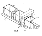
- articles 10 to be wrapped are transported from an upstream conveyor 11 to a downstream conveyor 12 via a wrapping material applicator 13 that incorporates a rotary ring 14.
- the upstream and downstream conveyors 11, 12 are spaced apart and the applicator 13 is disposed in the gap 15 between them.
- the applicator ring 14 rotates continuously about an axis that is substantially parallel to the longitudinal axes of the conveyors 11, 12 and dispenses wrapping material 16 from three reels 17 (one hidden in figure 1 ) disposed at angular intervals around a front face of the ring.
- the wrapping material on each reel 17 is in the form of a continuous elongate web of thin, stretchable synthetic plastics film such as a polyurethane based material.
- the film 16 is stretched and then wrapped in a helical fashion around them and any supporting material.
- the wrapping process continues as the articles progress along the conveyor such that the material is still wound in a helical fashion around the spaces between the articles so as to produce a continuous wrap of articles.
- the film is designed to recover from the stretching so that it shrinks tightly around the articles after wrapping.
- the upstream and downstream conveyors 11, 12 are both arranged in two adjacent sections and a cutting station 18 is interposed between adjacent sections 12a, 12b of the downstream conveyor 12. Here the individual articles are separated by cutting through the wrapping material in the space between adjacent articles 10.
- Further bands of wrapping material 19, 20 are drawn from a pair of reels 21, 22 disposed above and below the upstream conveyor 11.
- a lower one of the further bands 19 is unwound from a reel 21 under the upstream conveyor 11, emerges between the adjacent sections 11a, 11b of the upstream conveyor and is transported under articles 10 across the gap 15 to the downstream conveyor 12.
- This lower band 19 serves to facilitate the transfer of each article 10 across the gap 15 from the upstream to the downstream conveyors by providing a continuously running surface that moves with the conveyors.
- An upper band 20 is dispensed from a reel 22 disposed above the upstream conveyor 11 so as to overlie a top surface of the articles 10.
- Both the upper and lower bands 20, 19 may move in adhesion with the articles 10 and may be of the same or similar material to that of the main wrapping material film 16. It will be appreciated that as the articles 10 are wrapped by the applicator 13, the helical bands 16 also wrap around the upper and lower bands 20, 19 and in the process turn up or down around the article any exposed side edges of the bands. The completed wrapped article will thus have external helical wraps containing both the article 10 and the sheets of the upper and lower bands 20, 19 of wrapping material.
- the articles 10, the upper and lower bands 20, 19 of wrapping material and the conveyors 11, 12 all translate at effectively the same linear speed even if the downstream conveyor 12 is driven at a slightly faster speed than the upstream conveyor 11 as can be advantageous.
- a bracket or other form of support surface may be used to span the gap 15 and support the band 19 as it passes across the gap 15 as described for example in PCT/GB90/00266 .
- An upper conveyor 46 on the downstream side provides support for the packaged articles as they exit the wrapping applicator. It serves to prevent the packs from being twisted over on account of the forces applied by the applicator and serves to pull the wrapped articles through the apparatus.
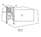
- the rotary ring 14 of the applicator 13 is supported in rotation by engagement with an adjacent fixed guide ring 23 that is on the downstream side.
- the rotary ring 14 has a plurality of rotary cam followers in the form of rollers 24 mounted on shafts 25 that are arranged at spaced angular intervals and extend from a rear face of the ring.
- the rollers 24 each have a grooved periphery 26 that rides on a complementary annular cam surface 27 on the periphery of the guide ring 23 which surface 27 takes the form of an inverted V-shape in section.
- the rotary ring 14 has an inner, toothed annular surface 28 and is driven in rotation by a pinion 29 that meshes with the toothed surface 28 and is mounted on the output shaft 30 of a servo controlled drive motor 31. As the rotary ring 14 rotates the cam follower rollers 24 ride and rotate over the peripheral cam surface 27 of the guide ring 23 in a smooth action.
- the guide ring 23 also defines an annular toothed surface 32 on its outer periphery. This toothed surface 32, seen most clearly in figure 5 , is immediately adjacent to the cam surface 27 and meshes with gears 33, 34, 35 that drive tensioning rollers 36 and 37 for applying a pre-stretch to the wrapping material 16 as it is unwound from the reels 17, as will described in more detail below.
- the reels 17 of the helical wrapping material 16 are each mounted on a shaft 38 that is rotatably supported on a respective bracket 39 extending radially from, and fixed to, the periphery of the rotary ring 14.
- the shafts 38 are arranged at equi-angular intervals around the front face of the ring 14 and each extends in a direction parallel to the rotary axis of the ring 14.
- the wrapping material 16 that is unwound from each reel 17 passes around a series of three rollers positioned in close proximity to the shaft 38 and extending in parallel thereto.
- rollers operate as an idler roller 40 that guides the direction of the unwound material and is rotatably mounted on the bracket 39 at a location spaced from the shaft 38 whilst the other two rollers are the tensioning rollers 36, 37 referred to above and that are rotatably supported on the front face of the rotary ring 14 with a small spacing therebetween, radially inwardly of the guide roller 40.
- a first of the tensioning rollers is a feed roller 36 and the other is an applicator roller 37.
- Both rollers 36, 37 are covered with a suitable friction coating or texturing that may be applied by laser deposition or other coating techniques, etching or knurling or the like to provide asperities on the roller surface that serve to grip the wrapping material as it passes over the rollers.
- Each of the tensioning rollers 36, 37 has a reduced diameter at one end so as to define a drive shaft 41 that passes through an aperture 42 in the rotary ring 14.
- corresponding gear wheels 33, 35 are mounted on each of the shafts 41 in a fixed relationship.
- the gear wheel 33 associated with the applicator roller 37 is disposed in a fixed radial location such that its teeth mesh with those defined on the toothed periphery 32 of the guide ring 23.
- the gear wheel 35 associated with the feed roller 36 is circumferentially spaced from the applicator gear 33 and is disposed at a fixed radial location such that its teeth are clear of those 32 defined on the outer periphery of the guide ring 23.
- an idler gear 34 Interposed between the applicator and feed gears 33, 35, in a meshing relationship, is an idler gear 34 that is mounted to the rear of the rotary ring 14 but which can be selectively disposed at one of three radial locations provided by three apertures in the ring (these are labelled as location A, B and C in figure 6 ).
- the tension (and therefore the pre-stretch) applied to the wrapping material 16 can be varied by changing the size of the applicator and feed gear wheels 33, 35 (which are removable) and moving the position of the idler gear 34 between locations A, B and C.
- the wrapping material is unwound from each reel 17 by the article 10 to be wrapped as the rotary ring 14 rotates.
- the wrapping material 16 from each reel 17 passes over the idler roller 40, under the feed roller 36 and over the applicator roller 37 from where it is drawn by the article 10 to be wrapped.
- the reel shaft 38 is connected to the idler roller 40 by a twisted elastomeric belt or band 43 (only one shown in figure 2 ) so as to ensure that they rotate at the same angular velocity and a constant tension is thereby applied to the film 16 as it is unwound from the reel 17, irrespective of the amount of material left of the reel and the size of the article to be wrapped.
- the applicator roller 37 is driven in rotation by virtue of the engagement of the applicator gear wheel 33 with the teeth 32 on the periphery of the guide ring 23.
- the applicator gear 33 in turn drives the idler gear 34 which then drives the feed gear 35 in the same direction of rotation as the applicator gear.
- the feed gear wheel 35 has a larger diameter than the applicator gear wheel 33 so that the applicator roller 37 rotates at a faster rate than the feed roller 36 and thereby stretches the wrapping material 16 before it is presented to the articles.
- the wrapping film material 16 is helically wound around them and the upper and lower bands 20, 19.
- the wrapped train of articles then passes the cutter station 18 where the helical wrapping film 16 is severed to leave individual packs of wrapped articles.
- the cutter station 18 comprises a frame 44 on which there is supported a heated horizontal wire that is moved in a vertical direction to heat and sever the wrapping material 16. The wrapping film naturally shrinks around the articles to provide for a self-contained wrapped package.
- FIG 7 An alternative cutting station configuration is shown in figure 7 in which two heated cutting beams 50, 51 are suspended from a horizontal support member 52 to extend in a vertical direction at the space between the downstream conveyors.
- the beams are made from a suitable metallic or ceramic material and contain an electric heating element such as a wire.
- the supported member contains a linear actuator, such as a hydraulic or pneumatic ram, to opposite ends of which the beams are fixed.
- One of the beams is movable relative to the other by actuation of the ram. The movement takes the beams from a spaced position where they are clear of the articles on each side of the conveyors and a cutting position where they are brought together. In the latter position the heated cutting beams are brought together to effect severance by heating of the wrapping film sandwiched between them.
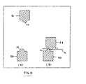
- the form of the cutting beams 50, 51 which can be seen from figure 8 is designed to provide a narrow cutting area, each comprises a raised arcuate cutting profile 52.
- One of the beams 51 is moved towards the other 52 from the rest position shown in figure 8(a) to that shown in figure 8(b) where the arcuate surfaces 52 come into contact to heat and sever the film 16 between them.
- the arcuate surface of the beam is generally heated to around typically 120°C in order to achieve effective severance.
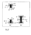
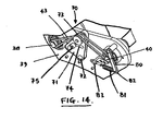
- the beams 60, 61 each comprise a base 62 that supports a pair of retractable outer sealing members 63 that flank an inner cutting member 64.
- the outer retractable sealing members 63 taper inwardly in a direction away from the base 62 and terminate in sealing tip portions 65 whereas each inner cutting member 64 is generally rectangular with a protruding cutting tip 66 at its exposed end.
- the outer sealing members 63 are spring mounted to the base 62 so that they are biased to a first position where their sealing tips 65 extend beyond the cutting tip 66 of the inner cutting member 64 (see figure 9(a) ).
- Both the sealing members 63 and the cutting member 64 are heated as before, the inner cutting member being heated, in use, to a first temperature designed to cut through the film and the sealing members are heated to a lower temperature that is only sufficient to fuse the film together.
- the tips 65 of the opposed sealing members 63 of the beams 62 first contact the wrapping film 16 together to effect sealing. Thereafter further movement of the beams 60, 61 brings the sealing members 63 into engagement and causes them to retract on the base and compress the springs 67.
- the sealing members are retracted the cutting member 64 of each beam is exposed and its tip 66 comes into contact with the film 16 so as to effect severance.
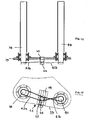
- Figures 10 and 11 show in detail the arrangement of the twisted elastomeric belt or band 43 that extends around the idler roller 40 and the reel shaft 38.
- the shaft and roller are mounted in journal bearings 60 in the bracket 39 and the band 43 such that one end projects from the rear face thereof.
- the band 43 is disposed in annular grooves 61 in the shaft and rollers at the rear ends
- a first band 43a is connected between the reel shaft 38 and the tensioning device 62 and the second band 43b is connected between the tensioning device 62 and the idler roller 40.
- the tensioning device 62 comprises a rotary stub shaft 63 that is moveable laterally of its axis of rotation along a guide track 64 by an adjustment knob 65 to vary the tension in the band.
- the tensioning device 70 is in the form of a pivoting arm 71 that comprises a triangular plate pivotally mounted on the support bracket 39 at a first apex by a pin 72.
- a tensioning roller 73 disposed at an opposite apex is designed to engage and tension the belt 43 extending between the reel shaft 38 and the idler roller 40.
- the arm 71 has an arcuate slot 74 that receives a fixed guide pin 75 projecting from the bracket 39 such that the slot 74 can over the pin 75 during pivoting movement of the arm 71. The length of the slot 74 thus limits the range of angular movement of the arm 71.
- the idler roller 40 is fitted with a braking system comprising a pivotal brake arm 80 mounted adjacent to the idler roller 40 and biased into contact with the circumferential surface of the roller 40 by a tensioning coil spring 81 connected between the end 82 of the brake arm 80 that is opposite the pivot and a fixed lug 83 mounted on the bracket 39 on the opposite side of the roller 40.
- the brake arm 80 is configured to apply a braking force to the idler roller 40 and for this purpose either comprises a slip resistant friction material or is coated, plated or otherwise covered, at least in part, with such a material.
- the brake arm 80 acts against the belt 43 and the idler roller 40 and thereby serves to brake the rotation of the idler roller 40 and therefore the film reel shaft 38.
- the brake arm 80 By operating against both the belt 43 and the roller 40 the brake arm 80 not only retards the film reel as it unwinds but also increases the tension with which the film is pulled from the reel 17.
- the connection between the coil spring 81 and the lug 83 is adjustable so that the braking force can be varied. This feature allows an operator to balance the tension in the wrapping material films 16 as they are unwound from each reel 17. In order to do this the operator will typically arrange for the films 16 to be unwound by a spring load balance device (not shown) and attach an appropriate tension measurement gauge across the width of the film. The tension in each of the films is then tuned by adjusting each of the coil spring tensions 81 applied to the brake arms 80. This arrangement also helps reduce chatter in the unwinding process.
- the wrapping film is typically in the region of 7 to 9 microns thick.
- the invention has many advantages compared to existing designs.
- the provision of the guide ring advantageously supports the rotation of the rotary ring and also enables the movement of the rotary ring to be used in driving the tensioning rollers.
- a gear train as the transmission between the guide ring and the rotary ring the requirement for differential drive speed or tensioning arrangements for those rollers can be eliminated.
- the invention provides for a packaging method that ensures that there is no significant waste wrapping material.
- the apparatus obviates the need for a separate heat shrink oven that would be unsuitable for certain types of heat sensitive articles (e.g. aerosols)
- the apparatus has a relatively small size compared to existing designs.
- lower film band 19 is not essential if a low friction plate or bracket is used to bridge the gap 15 and the friction characteristics of the conveyor belts are high enough to enable the articles to be transported across the gap between upstream and downstream conveyors.
- the upper film band 20 is not essential and is generally only to be used where the article have sharp edges or other protrusions that have a tendency to pierce the helical wrapping film.
- the present invention has the advantage that there is no need to alter the machine set-up for different size and shapes of articles. Generally prior art machines use a different width film for different width products.
- the apparatus is designed to use thin pre-stretched film with folded edges to give strapping resistance to the pack.
- the helical wrapping film obviates the need for other packing elements such as boxes, trays etc.
- the texture of the belts is designed to optimise the friction between the articles and the belt surface.
- the wrapping apparatus may have applications outside of packaging of articles with synthetic plastics film.
- the same invention could be used to wrap any elongate flexible material such as a textile, fibres, strips of material, metal composite bands or the like to an article to create any sort of structural component.
Landscapes
- Engineering & Computer Science (AREA)
- Mechanical Engineering (AREA)
- Basic Packing Technique (AREA)
- Supplying Of Containers To The Packaging Station (AREA)
- Auxiliary Devices For And Details Of Packaging Control (AREA)
Claims (31)
- Verpackungsvorrichtung zum spiralförmigen Einwickeln von Artikeln (10), die einen Einwickelmaterial-Applikator (13), eine erste Förderanlage (11) zum Befördern nicht eingewickelter Artikel hin zu dem Applikator und eine zweite Förderanlage (12) zum Befördern von Artikeln, die durch den Applikator spiralförmig mit flexiblem Bahn-Einwickelmaterial (16) eingewickelt worden sind, umfasst, wobei die erste und die zweite Förderanlage (11, 12) mit Zwischenraum zueinander angeordnet sind, wobei der Einwickelmaterial-Applikator (13) zwischen der ersten und der zweiten Förderanlage (11, 12) angeordnet ist und bei Anwendung dazu dient, das Einwickelmaterial (16) zwischen der ersten und der mit Zwischenraum angeordneten zweiten Förderanlage hindurchzuführen, um es so um einen in dem Raum (15) zwischen den Förderanlagen angeordneten Artikel zu wickeln und denselben einzuwickeln, wobei der Applikator ein Rotationselement (14) und ein feststehendes Führungselement (23), wobei das Rotationselement im Verhältnis zu dem Führungselement gedreht werden kann und in der Drehung durch dasselbe getragen wird, wenigstens eine Trommelwelle (38) zum Tragen einer Trommel (17) von Einwickelmaterial (16), die an dem Rotationselement (14) angebracht ist, und einer Umlenkrolle (40) angrenzend an die oder jede Trommelwelle (38), um das Einwickelmaterial zu führen, wenn es von der Trommel (17) abgewickelt wird, mehrere Rotationsspannrollen (36, 37), die an dem Rotationselement (14) getragen werden und zum Ausüben einer Spannung auf das Einwickelmaterial (16) dienen, ein Antriebselement (29, 30, 31) zum Antreiben des Rotationselementes in Drehung im Verhältnis zu dem Fübrungselement (23) und eine Übertragungseinrichtung (33, 34, 35) zwischen dem Rotationselement: (14) und dem Führungselement (23), um die relative Bewegung des Rotationselementes (14) und des Führungselementes (23) in eine Drehung der Spannrollen (36, 37) umzuwandeln, umfasst, dadurch gekennzeichnet, dass das Führungselement (23) eine Fläche (32) hat, die treibend mit der Übertragungseinrichtung (33, 34, 35) verbunden ist, um so ein Antreiben der Spannrollen (36, 37) in Drehung mit unterschiedlichen Rotationsgeschwindigkeiten zu ermöglichen, um so einen Zug oder eine Spannung auf das Einwickelmaterial (16) auszuüben, und dadurch, dass die Umlenkrolle (40) durch einen Endlosschleifenriemen (43) mit der Trommelwelle (38) verbunden ist, um sie so bei im Wesentlichen der gleichen Rotationsgeschwindigkeit zu halten.
- Verpackungsvorrichtung nach Anspruch 1, wobei das Antriebselement (29, 30, 31) mit einer Fläche (28) des Rotationselementes (14) ineinandergreift, um es so in Drehung anzutreiben.
- Verpackungsvorrichtung nach Anspruch 1 oder 2, wobei das Rotationselement (14) die Form eines Kreisrings mit einer Innenfläche (28) für einen Antriebseingriff mit dem Antriebselement (29, 30, 31) hat.
- Verpackungsvorrichtung nach Anspruch 3, wobei die Innenfläche (28) eine gezahnte Fläche für einen Eingriff mit einem Zahnrad (29) des Antriebselementes (29, 30, 31) ist.
- Verpackungsvorrichtung nach einem der vorhergehenden Ansprüche, wobei das Führungselement (23) eine ringförmige Führungsfläche (27) umfasst, auf der das Rotationselement (14) in Drehung getragen wird.
- Verpackungsvorrichtung nach Anspruch 5, wobei die ringförmige Führungsfläche (27) eine Nockenfläche ist, die mit wenigstens einem an dem Rotationselement (14) angebrachten Nockenstößel (24) in Eingriff gebracht wird.
- Verpackungsvorrichtung nach Anspruch 6, wobei die Nockenfläche (27) eine ringförmige Rippe ist, die mit entsprechenden Aussparungen in dem Nockenstößel (24) ineinandergreift.
- Verpackungsvorrichtung nach Anspruch 6 oder 7, wobei der Nockenstößel (24) die Form einer Rolle mit einer Aussparung in derselben hat.
- Verpackungsvorrichtung nach einem der vorhergehenden Ansprüche, wobei die Übertragungseinrichtung (33, 34, 35) die Form eines Getriebezuges hat, der Getrieberäder (33, 35) umfasst, die an den Spannrollen (36, 37) befestigt sind,
- Verpackungsvorrichtung nach Anspruch 9, wobei die Fläche (32) des Führungselementes (23) eine ringförmige, gezahnte Fläche ist, die mit den Getriebezahnrädern (33, 35) der Spannrollen (36, 37) ineinandergreift.
- Verpackungsvorrichtung nach Anspruch 10, wobei es ein Zwischenrad (34) zwischen den Getrieberädern (33, 35) der Spannrollen (36, 37) gibt.
- Verpackungsvorrichtung nach Anspruch 11, die ferner mehrere Öffnungen in dem Rotationsring (14) umfasst, die alternative Positionen für das Zwischenrad (34) bieten.
- Verpackungsvorrichtung nach einem der Ansprüche 10 bis 12, wobei ein erstes Getrieberad (33), das mit einer ersten Spannrolle (37) verbunden ist, und ein zweites Getrieberad (35), das mit einer zweiten Spannrolle (36) verbunden ist, bereitgestellt werden, wobei sich das erste Getrieberad (33) in Eingriff mit der ringförmigen gezahnten Fläche (32) des Führungselementes (23) befindet.
- Verpackungsvorrichtung nach Anspruch 13, wobei das erste und das zweite Getrieberad (33, 35) unterschiedliche Größen haben, um Differenzwinkelgeschwindigkeiten zu ermöglichen, um so bei Anwendung Spannung auf das Einwickelmaterial (16) auszuüben.
- Verpackungsvorrichtung nach einem der Ansprüche 10 bis 14, wobei sich die ringförmige gezahnte Fläche (32) angrenzend an die Nockenfläche (27) des Führungselementes (23) befindet.
- Verpackungsvorrichtung nach einem der vorhergehenden Ansprüche, wobei es mehrere mit Zwischenraum um das Rotationselement (14) angeordnete Trommelwellen (38) gibt.
- Verpackungsvorrichtung nach einem der vorhergehenden Ansprüche, wobei eine Trommel (21) von Einwickelmaterial bereitgestellt wird, um ein Band (19) von Einwickelmaterial unter die einzuwickelnden Artikel (10) zu legen.
- Verpackungsvorrichtung nach einem der vorhergehenden Ansprüche, wobei eine Schneidstation (18) bereitgestellt wird, die wenigstens zwei beheizte längliche Schneidelemente (50, 51; 60, 61) umfasst, die bewegt werden können zwischen einer ersten Stellung, in der sie von den eingewickelten Artikeln (10) entfernt sind, und einer zweiten Stellung, in der sie in einem Raum zwischen benachbarten eingewickelten Artikeln zusammengebracht werden, um das Einwickelmaterial zu durchtrennen.
- Verpackungsvorrichtung nach Anspruch 18, wobei die Schneidelemente (50, 51) die Form von Balken haben, jeweils mit einem erhöhten Anschnitt (52), der eine Schneidfläche definiert.
- Verpackungsvorrichtung nach Anspruch 18, wobei die Schneidelemente wenigstens ein einziehbares Versiegelungselement (63), das eine Versiegelungsspitze (65) hat, und wenigstens ein Schneidelement (64), das wenigstens eine Schneidspitze (66) hat, umfassen, wobei die Versiegelungselemente (63) eingezogen werden können von einer ersten Stellung, in der sich die Versiegelungsspitze (65) über die Schneidspitze (66) des Schneidelementes (64) hinaus erstreckt, zu einer zweiten Stellung, in der sich die Schneidspitze (66) über die Versiegelungsspitze (65) hinaus erstreckt.
- Verpackungsvorrichtung nach Anspruch 18, wobei Mittel zum Heizen des Schneidelementes (64) auf eine erste Temperatur und zum Heizen des Versiegelungselementes (63) auf eine zweite Temperatur bereitgestellt werden, wobei die erste Temperatur höher ist als die zweite Temperatur.
- Verpackungsvorrichtung nach Anspruch 20 oder 21, wobei die einziehbaren Versiegelungselemente (63) zu der ersten Stellung vorgespannt werden.
- Verpackungsvorrichtung nach Anspruch 22, wobei die Versiegelungselemente (63) durch Federn (67) vorgespannt werden, die zwischen ihnen und einem Basiselement (62) des Schneidelementes angebracht sind.
- Verpackungsvorrichtung nach einem der vorhergehenden Ansprüche, wobei die Rotationsachse des Applikators (13) im Wesentlichen parallel zu einer Längsachse der Förderanlagen (11, 12) ist.
- Verpackungsvorrichtung nach einem der vorhergehenden Ansprüche, wobei die Spannrollen (36, 37) jeweils eine Oberfläche haben, die behandelt ist, um die Reibung zwischen der Oberfläche und dem Einwickelmaterial zu steigern.
- Verpackungsvorrichtung nach Anspruch 25, wobei die Oberfläche der Spannrollen (36, 37) aufgeraut ist.
- Verpackungsvorrichtung nach Anspruch 25, wobei die Reibungsbeschichtung auf die Rollenoberfläche aufgebracht oder aufgetragen ist.
- Verpackungsvorrichtung nach einem der vorhergehenden Ansprüche, wobei es eine Bremse (80) zum Ausüben einer Bremskraft auf die Umlenkrolle (40) gibt.
- Verpackungsvorrichtung nach Anspruch 28, wobei die Bremse (80) einen Einstellmechanismus zum Einstellen der Größe der Bremskraft hat.
- Verfahren zum Verpacken von Artikeln unter Verwendung eines Einwickelmaterial-Applikators (13), der zwischen der ersten und der zweiten Förderanlage (11, 12) angeordnet ist, wobei das Verfahren die Schritte umfasst, einzuwickelnde Artikel (10) hin zu dem Applikator zu befördern, wobei der Applikator ein Rotationselement (14), das wenigstens eine Trommel (17) von Einwickelmaterial (16) trägt, und mehrere Spannrollen (36, 37) hat, das Rotationselement des Applikators zu drehen und die Drehung an einem Führungselement (23) zu tragen, wobei das Einwickelmaterial, wenn sich das Rotationselement dreht, durch die Artikel von der Trommel abgezogen und, wenn es von der Trommel abgewickelt wird, durch eine Umlenkrolle (40) geführt wird, gekennzeichnet durch die Verwendung der relativen Drehung des Rotationselementes (14) und des Führungselementes (23), um die Drehung von Spannrollen (36, 37) über eine Übertragungseinrichtung (33, 34, 35) in Drehung mit unterschiedlichen Rotationsgeschwindigkeiten anzutreiben, um einen Zug auf das Einwickelmaterial (16) auszuüben, bevor es die Artikel (10) berührt, und durch das Halten der Umlenkrolle (40) und der Trommel (17) bei im Wesentlichen der gleichen Rotationsgeschwindigkeit durch Verbinden derselben durch einen Endlosschleifenriemen (43).
- Verfahren nach Anspruch 30, wobei die Artikel (10) fortlaufend eingewickelt werden, wenn sie durch die Förderanlagen (11, 12) in einer Richtung, im Wesentlichen parallel zu einer Rotationsachse des Applikators (13), bewegt werden.
Applications Claiming Priority (2)
| Application Number | Priority Date | Filing Date | Title |
|---|---|---|---|
| GB0424754A GB0424754D0 (en) | 2004-11-10 | 2004-11-10 | Packaging method and apparatus |
| PCT/GB2005/004307 WO2006051281A1 (en) | 2004-11-10 | 2005-11-09 | Packaging method and apparatus |
Publications (2)
| Publication Number | Publication Date |
|---|---|
| EP1809536A1 EP1809536A1 (de) | 2007-07-25 |
| EP1809536B1 true EP1809536B1 (de) | 2010-03-10 |
Family
ID=33523432
Family Applications (1)
| Application Number | Title | Priority Date | Filing Date |
|---|---|---|---|
| EP05807865A Ceased EP1809536B1 (de) | 2004-11-10 | 2005-11-09 | Verpackungsverfahren und -vorrichtung |
Country Status (6)
| Country | Link |
|---|---|
| US (1) | US7661244B2 (de) |
| EP (1) | EP1809536B1 (de) |
| AT (1) | ATE460341T1 (de) |
| DE (1) | DE602005019909D1 (de) |
| GB (1) | GB0424754D0 (de) |
| WO (1) | WO2006051281A1 (de) |
Families Citing this family (26)
| Publication number | Priority date | Publication date | Assignee | Title |
|---|---|---|---|---|
| US20070220840A1 (en) * | 2006-03-21 | 2007-09-27 | Robopac S.A. | Apparatus for wrapping objects |
| GB0911999D0 (en) * | 2009-07-10 | 2009-08-19 | Oakbridge Invest Ltd | Packaging method and apparatus |
| CA2775966C (en) * | 2009-10-21 | 2013-06-11 | Jason David Kenney | Banding of products |
| US8356456B2 (en) * | 2010-03-04 | 2013-01-22 | Douglas Machine Inc. | Apparatus for adjustable wrapping |
| GB201314963D0 (en) | 2013-08-21 | 2013-10-02 | Oakbridge Invest Ltd | Packaging method and apparatus |
| GB201319532D0 (en) | 2013-11-05 | 2013-12-18 | Oakbridge Invest Ltd | Apparatus and method for cutting and/or crimping wrapping material |
| CN104354890B (zh) * | 2014-10-29 | 2016-07-06 | 江阴市巨匠文化创意发展有限公司 | 一种包装机 |
| US20190009937A1 (en) * | 2016-03-30 | 2019-01-10 | Krones Ag | An apparatus and a method for packaging piece goods and in particular containers |
| DE102016106265A1 (de) * | 2016-04-06 | 2017-10-12 | Krones Ag | Verfahren und Vorrichtung zum Verpacken und/oder Gruppieren von Artikeln |
| WO2017189872A1 (en) | 2016-04-28 | 2017-11-02 | Lantech.Com, Llc | Automatic roll change for stretch wrapping machine |
| IT201600103903A1 (it) * | 2016-10-17 | 2018-04-17 | Colines Spa | Macchina e metodo perfezionati di imballaggio in pellicola estensibile di prodotti alimentati a gruppi o singolarmente |
| ES2779853T3 (es) * | 2017-07-14 | 2020-08-20 | Multivac Haggenmueller Kg | Máquina de embalaje por embutición profunda con soporte de paquetes flexible |
| US11136151B1 (en) * | 2018-04-23 | 2021-10-05 | Michael Baker | Orbital wrapping machine |
| US10697437B1 (en) * | 2019-08-27 | 2020-06-30 | Bnsf Logistics, Llc | Rotatable support fixture for wind turbine blade |
| US11738895B2 (en) * | 2019-10-11 | 2023-08-29 | Wulftec International Inc. | Apparatus for wrapping a load and associated methods |
| CN111516922B (zh) * | 2020-05-29 | 2024-06-04 | 杭州萱博健身器材有限公司 | 一种胶带打包机及使用方法 |
| CN111591495B (zh) * | 2020-06-03 | 2021-12-21 | 张翠玲 | 一种农用蔬菜捆扎装置 |
| CN112478229B (zh) * | 2020-12-21 | 2022-02-15 | 湖南翰坤实业有限公司 | 一种防护门立柱用智能打包机 |
| CN112644755B (zh) * | 2020-12-29 | 2022-07-12 | 无锡爱邦辐射技术有限公司 | 一种机械设备加工用工件包覆设备 |
| US20220204197A1 (en) * | 2020-12-31 | 2022-06-30 | Encore Packaging Llc | Wrapping Apparatus and Attachment |
| IT202100026789A1 (it) * | 2021-10-19 | 2023-04-19 | Robopac Spa | Macchina avvolgitrice orizzontale |
| CN114802859A (zh) * | 2022-05-18 | 2022-07-29 | 上海翔图纸品有限公司 | 一种缠绕机 |
| CN116215946B (zh) * | 2023-03-29 | 2025-08-26 | 安徽以诺木塑板材科技有限公司 | 一种堆叠pvc木塑板覆膜打包装置 |
| CN116986086B (zh) * | 2023-05-19 | 2025-12-05 | 苏州市协和药业有限公司 | 绕圈封箱机 |
| US20250326511A1 (en) * | 2024-04-19 | 2025-10-23 | BW Flexible Systems | Heat-sealing apparatus for wrapping articles |
| CN119408784B (zh) * | 2025-01-08 | 2025-03-21 | 和峻(广州)胶管有限公司 | 一种胶管保护膜自动缠绕装置 |
Family Cites Families (21)
| Publication number | Priority date | Publication date | Assignee | Title |
|---|---|---|---|---|
| US1215930A (en) * | 1913-03-19 | 1917-02-13 | Albert J Hadert | Wrapping-machine. |
| US4302920A (en) * | 1979-11-21 | 1981-12-01 | Lantech Inc. | Film web drive stretch wrapping apparatus and process |
| US4317322A (en) * | 1980-05-20 | 1982-03-02 | Lantech, Inc. | Rotatable film wrapping apparatus with wrap carrying mechanism |
| US4524568A (en) * | 1982-08-27 | 1985-06-25 | Lantech, Inc. | Power assisted rotatable film wrapping apparatus |
| US4712354A (en) * | 1984-02-23 | 1987-12-15 | Lantech, Inc. | Dual rotating stretch wrapping apparatus and process |
| IT1184905B (it) * | 1985-03-13 | 1987-10-28 | Val Mec Srl | Apparecchiatura per avviluppare una confezione mediante una pellicola stirabile e successivamente retraibile a fredo e o a caldo |
| WO1990009316A1 (en) * | 1989-02-18 | 1990-08-23 | Elmwood Packaging Machinery Limited | Packaging method and apparatus |
| US5027579A (en) * | 1989-05-31 | 1991-07-02 | Keip Machine Company | Wrapping apparatus |
| FR2651481B1 (fr) * | 1989-09-06 | 1991-12-20 | Newtec Int | Chariot de devidement de film pour machine d'emballage. |
| US5012631A (en) * | 1989-12-27 | 1991-05-07 | Deweze Manufacturing, Inc. | Bale wrapper |
| US5027581A (en) * | 1990-05-30 | 1991-07-02 | Hayssen Manufacturing Company | Wrapping method and apparatus |
| US5285891A (en) * | 1992-06-01 | 1994-02-15 | Liberty Industries | Conveyor for rotary film wrapping apparatus |
| US5311725A (en) * | 1992-07-30 | 1994-05-17 | Lantech, Inc. | Stretch wrapping with tension control |
| CA2105203C (en) * | 1992-10-30 | 1998-12-15 | Gale W. Huson | Method for wrapping elongate load with wrapping film, apparatus therefor, and film-perforating mechanism |
| US5433058A (en) * | 1993-04-22 | 1995-07-18 | Peterson; Robert W. | System, method, and apparatus for packaging bales of hay |
| US5531061A (en) * | 1993-04-22 | 1996-07-02 | Peterson; Robert W. | System and method for packaging bales of hay and an improved wrapping apparatus |
| AU676117B1 (en) * | 1995-09-22 | 1997-02-27 | Itw Limited | Film stretching mechanism |
| US5799471A (en) * | 1996-09-26 | 1998-09-01 | Chen; Tsung-Yen | Steplessly adjustable pre-stretched film wrapping apparatus |
| JP2949489B2 (ja) * | 1998-02-10 | 1999-09-13 | シンエイテック株式会社 | 包装装置 |
| FI105666B (fi) | 1998-02-11 | 2000-09-29 | Haloila M Oy Ab | Käärintälaite |
| JP3622078B2 (ja) * | 2000-04-04 | 2005-02-23 | 松本システムエンジニアリング株式会社 | 荷体包装方法及びその装置 |
-
2004
- 2004-11-10 GB GB0424754A patent/GB0424754D0/en not_active Ceased
-
2005
- 2005-11-09 US US11/719,073 patent/US7661244B2/en active Active
- 2005-11-09 AT AT05807865T patent/ATE460341T1/de not_active IP Right Cessation
- 2005-11-09 WO PCT/GB2005/004307 patent/WO2006051281A1/en not_active Ceased
- 2005-11-09 EP EP05807865A patent/EP1809536B1/de not_active Ceased
- 2005-11-09 DE DE602005019909T patent/DE602005019909D1/de not_active Expired - Lifetime
Also Published As
| Publication number | Publication date |
|---|---|
| US20080184676A1 (en) | 2008-08-07 |
| DE602005019909D1 (de) | 2010-04-22 |
| GB0424754D0 (en) | 2004-12-08 |
| ATE460341T1 (de) | 2010-03-15 |
| WO2006051281A1 (en) | 2006-05-18 |
| EP1809536A1 (de) | 2007-07-25 |
| US7661244B2 (en) | 2010-02-16 |
Similar Documents
| Publication | Publication Date | Title |
|---|---|---|
| EP1809536B1 (de) | Verpackungsverfahren und -vorrichtung | |
| CA1066604A (en) | Reverse wrapping package and process | |
| US4712354A (en) | Dual rotating stretch wrapping apparatus and process | |
| JP2948908B2 (ja) | ウェブ材料を切断するための装置を備えたウェブ材料の巻物の形成のための巻戻し機械及び方法 | |
| EP2451713B1 (de) | Verpackungsverfahren und -vorrichtung | |
| US4651500A (en) | Method and apparatus for wrapping rolls of paper | |
| FR2486022A1 (fr) | Procede et appareil d'emballage | |
| US4984413A (en) | Machine and method for overwrapping cylindrical articles | |
| FR2584054A1 (fr) | Dispositif de commande de deroulement d'un film en matiere plastique dans une machine de conditionnement. | |
| CA1244751A (en) | Dual rotating stretch wrapping apparatus and process | |
| US5946884A (en) | Wrapping machine and method for use with polyethylene wrap | |
| CN108602573A (zh) | 连续进给产品的可伸展膜的包装方法和机器 | |
| NZ258070A (en) | Stretched plastics film; comprises a roll of film with an embossed surface and a folded edge; method and apparatus for producing such film | |
| JPH04279409A (ja) | 伸張包装材料のシートで荷を伸張包装するための方法及び装置 | |
| EP0388561A2 (de) | Dehnfolien-Einwickelvorrichtung | |
| US4716707A (en) | Apparatus for shrink-wrapping articles with handles | |
| JPH0725366B2 (ja) | 円筒状物品の包装装置 | |
| US3922834A (en) | Apparatus for closing of wrapping bags or sleeves | |
| US4293100A (en) | Apparatus for ganging and cutting a plurality of layers of strip material | |
| FI57712B (fi) | Foerfarande och anordning foer framstaellning av en hylsa | |
| EP3953283B1 (de) | Zuführeinheit zum zuführen einer kunststofffolie in verpackungsmaschinen | |
| US5070676A (en) | Stretch bundling | |
| US4218945A (en) | Apparatus for ganging and cutting a plurality of layers of strip material | |
| EP0043171B1 (de) | Apparat zum Verpacken von kontinuierlich zugeführten Artikeln | |
| NL1007204C2 (nl) | Inrichting voor het aanbrengen van scheurstrips. |
Legal Events
| Date | Code | Title | Description |
|---|---|---|---|
| PUAI | Public reference made under article 153(3) epc to a published international application that has entered the european phase |
Free format text: ORIGINAL CODE: 0009012 |
|
| 17P | Request for examination filed |
Effective date: 20070521 |
|
| AK | Designated contracting states |
Kind code of ref document: A1 Designated state(s): AT BE BG CH CY CZ DE DK EE ES FI FR GB GR HU IE IS IT LI LT LU LV MC NL PL PT RO SE SI SK TR |
|
| DAX | Request for extension of the european patent (deleted) | ||
| 17Q | First examination report despatched |
Effective date: 20080310 |
|
| GRAP | Despatch of communication of intention to grant a patent |
Free format text: ORIGINAL CODE: EPIDOSNIGR1 |
|
| GRAS | Grant fee paid |
Free format text: ORIGINAL CODE: EPIDOSNIGR3 |
|
| GRAA | (expected) grant |
Free format text: ORIGINAL CODE: 0009210 |
|
| AK | Designated contracting states |
Kind code of ref document: B1 Designated state(s): AT BE BG CH CY CZ DE DK EE ES FI FR GB GR HU IE IS IT LI LT LU LV MC NL PL PT RO SE SI SK TR |
|
| REG | Reference to a national code |
Ref country code: GB Ref legal event code: FG4D |
|
| REG | Reference to a national code |
Ref country code: CH Ref legal event code: EP |
|
| REG | Reference to a national code |
Ref country code: IE Ref legal event code: FG4D |
|
| REF | Corresponds to: |
Ref document number: 602005019909 Country of ref document: DE Date of ref document: 20100422 Kind code of ref document: P |
|
| REG | Reference to a national code |
Ref country code: NL Ref legal event code: VDEP Effective date: 20100310 |
|
| PG25 | Lapsed in a contracting state [announced via postgrant information from national office to epo] |
Ref country code: LT Free format text: LAPSE BECAUSE OF FAILURE TO SUBMIT A TRANSLATION OF THE DESCRIPTION OR TO PAY THE FEE WITHIN THE PRESCRIBED TIME-LIMIT Effective date: 20100310 |
|
| LTIE | Lt: invalidation of european patent or patent extension |
Effective date: 20100310 |
|
| PG25 | Lapsed in a contracting state [announced via postgrant information from national office to epo] |
Ref country code: LV Free format text: LAPSE BECAUSE OF FAILURE TO SUBMIT A TRANSLATION OF THE DESCRIPTION OR TO PAY THE FEE WITHIN THE PRESCRIBED TIME-LIMIT Effective date: 20100310 Ref country code: FI Free format text: LAPSE BECAUSE OF FAILURE TO SUBMIT A TRANSLATION OF THE DESCRIPTION OR TO PAY THE FEE WITHIN THE PRESCRIBED TIME-LIMIT Effective date: 20100310 Ref country code: AT Free format text: LAPSE BECAUSE OF FAILURE TO SUBMIT A TRANSLATION OF THE DESCRIPTION OR TO PAY THE FEE WITHIN THE PRESCRIBED TIME-LIMIT Effective date: 20100310 Ref country code: PL Free format text: LAPSE BECAUSE OF FAILURE TO SUBMIT A TRANSLATION OF THE DESCRIPTION OR TO PAY THE FEE WITHIN THE PRESCRIBED TIME-LIMIT Effective date: 20100310 Ref country code: SI Free format text: LAPSE BECAUSE OF FAILURE TO SUBMIT A TRANSLATION OF THE DESCRIPTION OR TO PAY THE FEE WITHIN THE PRESCRIBED TIME-LIMIT Effective date: 20100310 |
|
| PG25 | Lapsed in a contracting state [announced via postgrant information from national office to epo] |
Ref country code: SE Free format text: LAPSE BECAUSE OF FAILURE TO SUBMIT A TRANSLATION OF THE DESCRIPTION OR TO PAY THE FEE WITHIN THE PRESCRIBED TIME-LIMIT Effective date: 20100310 Ref country code: GR Free format text: LAPSE BECAUSE OF FAILURE TO SUBMIT A TRANSLATION OF THE DESCRIPTION OR TO PAY THE FEE WITHIN THE PRESCRIBED TIME-LIMIT Effective date: 20100611 Ref country code: NL Free format text: LAPSE BECAUSE OF FAILURE TO SUBMIT A TRANSLATION OF THE DESCRIPTION OR TO PAY THE FEE WITHIN THE PRESCRIBED TIME-LIMIT Effective date: 20100310 Ref country code: RO Free format text: LAPSE BECAUSE OF FAILURE TO SUBMIT A TRANSLATION OF THE DESCRIPTION OR TO PAY THE FEE WITHIN THE PRESCRIBED TIME-LIMIT Effective date: 20100310 Ref country code: BE Free format text: LAPSE BECAUSE OF FAILURE TO SUBMIT A TRANSLATION OF THE DESCRIPTION OR TO PAY THE FEE WITHIN THE PRESCRIBED TIME-LIMIT Effective date: 20100310 Ref country code: CY Free format text: LAPSE BECAUSE OF FAILURE TO SUBMIT A TRANSLATION OF THE DESCRIPTION OR TO PAY THE FEE WITHIN THE PRESCRIBED TIME-LIMIT Effective date: 20100310 Ref country code: ES Free format text: LAPSE BECAUSE OF FAILURE TO SUBMIT A TRANSLATION OF THE DESCRIPTION OR TO PAY THE FEE WITHIN THE PRESCRIBED TIME-LIMIT Effective date: 20100621 Ref country code: EE Free format text: LAPSE BECAUSE OF FAILURE TO SUBMIT A TRANSLATION OF THE DESCRIPTION OR TO PAY THE FEE WITHIN THE PRESCRIBED TIME-LIMIT Effective date: 20100310 |
|
| PG25 | Lapsed in a contracting state [announced via postgrant information from national office to epo] |
Ref country code: SK Free format text: LAPSE BECAUSE OF FAILURE TO SUBMIT A TRANSLATION OF THE DESCRIPTION OR TO PAY THE FEE WITHIN THE PRESCRIBED TIME-LIMIT Effective date: 20100310 Ref country code: IS Free format text: LAPSE BECAUSE OF FAILURE TO SUBMIT A TRANSLATION OF THE DESCRIPTION OR TO PAY THE FEE WITHIN THE PRESCRIBED TIME-LIMIT Effective date: 20100710 Ref country code: CZ Free format text: LAPSE BECAUSE OF FAILURE TO SUBMIT A TRANSLATION OF THE DESCRIPTION OR TO PAY THE FEE WITHIN THE PRESCRIBED TIME-LIMIT Effective date: 20100310 Ref country code: BG Free format text: LAPSE BECAUSE OF FAILURE TO SUBMIT A TRANSLATION OF THE DESCRIPTION OR TO PAY THE FEE WITHIN THE PRESCRIBED TIME-LIMIT Effective date: 20100610 |
|
| PLBE | No opposition filed within time limit |
Free format text: ORIGINAL CODE: 0009261 |
|
| STAA | Information on the status of an ep patent application or granted ep patent |
Free format text: STATUS: NO OPPOSITION FILED WITHIN TIME LIMIT |
|
| PG25 | Lapsed in a contracting state [announced via postgrant information from national office to epo] |
Ref country code: DK Free format text: LAPSE BECAUSE OF FAILURE TO SUBMIT A TRANSLATION OF THE DESCRIPTION OR TO PAY THE FEE WITHIN THE PRESCRIBED TIME-LIMIT Effective date: 20100310 |
|
| 26N | No opposition filed |
Effective date: 20101213 |
|
| PG25 | Lapsed in a contracting state [announced via postgrant information from national office to epo] |
Ref country code: IT Free format text: LAPSE BECAUSE OF FAILURE TO SUBMIT A TRANSLATION OF THE DESCRIPTION OR TO PAY THE FEE WITHIN THE PRESCRIBED TIME-LIMIT Effective date: 20100310 |
|
| PG25 | Lapsed in a contracting state [announced via postgrant information from national office to epo] |
Ref country code: MC Free format text: LAPSE BECAUSE OF NON-PAYMENT OF DUE FEES Effective date: 20101130 |
|
| REG | Reference to a national code |
Ref country code: CH Ref legal event code: PL |
|
| PG25 | Lapsed in a contracting state [announced via postgrant information from national office to epo] |
Ref country code: LI Free format text: LAPSE BECAUSE OF NON-PAYMENT OF DUE FEES Effective date: 20101130 Ref country code: CH Free format text: LAPSE BECAUSE OF NON-PAYMENT OF DUE FEES Effective date: 20101130 |
|
| PG25 | Lapsed in a contracting state [announced via postgrant information from national office to epo] |
Ref country code: IE Free format text: LAPSE BECAUSE OF NON-PAYMENT OF DUE FEES Effective date: 20101109 |
|
| PG25 | Lapsed in a contracting state [announced via postgrant information from national office to epo] |
Ref country code: HU Free format text: LAPSE BECAUSE OF FAILURE TO SUBMIT A TRANSLATION OF THE DESCRIPTION OR TO PAY THE FEE WITHIN THE PRESCRIBED TIME-LIMIT Effective date: 20100911 Ref country code: LU Free format text: LAPSE BECAUSE OF NON-PAYMENT OF DUE FEES Effective date: 20101109 |
|
| PG25 | Lapsed in a contracting state [announced via postgrant information from national office to epo] |
Ref country code: TR Free format text: LAPSE BECAUSE OF FAILURE TO SUBMIT A TRANSLATION OF THE DESCRIPTION OR TO PAY THE FEE WITHIN THE PRESCRIBED TIME-LIMIT Effective date: 20100310 |
|
| PG25 | Lapsed in a contracting state [announced via postgrant information from national office to epo] |
Ref country code: PT Free format text: LAPSE BECAUSE OF NON-PAYMENT OF DUE FEES Effective date: 20100310 |
|
| REG | Reference to a national code |
Ref country code: FR Ref legal event code: PLFP Year of fee payment: 11 |
|
| REG | Reference to a national code |
Ref country code: FR Ref legal event code: PLFP Year of fee payment: 12 |
|
| REG | Reference to a national code |
Ref country code: FR Ref legal event code: PLFP Year of fee payment: 13 |
|
| REG | Reference to a national code |
Ref country code: FR Ref legal event code: PLFP Year of fee payment: 14 |
|
| PGFP | Annual fee paid to national office [announced via postgrant information from national office to epo] |
Ref country code: FR Payment date: 20201013 Year of fee payment: 16 Ref country code: GB Payment date: 20201028 Year of fee payment: 16 Ref country code: DE Payment date: 20201028 Year of fee payment: 16 |
|
| REG | Reference to a national code |
Ref country code: DE Ref legal event code: R119 Ref document number: 602005019909 Country of ref document: DE |
|
| GBPC | Gb: european patent ceased through non-payment of renewal fee |
Effective date: 20211109 |
|
| PG25 | Lapsed in a contracting state [announced via postgrant information from national office to epo] |
Ref country code: GB Free format text: LAPSE BECAUSE OF NON-PAYMENT OF DUE FEES Effective date: 20211109 Ref country code: DE Free format text: LAPSE BECAUSE OF NON-PAYMENT OF DUE FEES Effective date: 20220601 |
|
| PG25 | Lapsed in a contracting state [announced via postgrant information from national office to epo] |
Ref country code: FR Free format text: LAPSE BECAUSE OF NON-PAYMENT OF DUE FEES Effective date: 20211130 |