EP1808393A1 - Vorrichtung und Verfahren zur Vorbereitung eines eine gewünschte Länge aufweisenden Klebebandabschnittes aus einer Spule - Google Patents
Vorrichtung und Verfahren zur Vorbereitung eines eine gewünschte Länge aufweisenden Klebebandabschnittes aus einer Spule Download PDFInfo
- Publication number
- EP1808393A1 EP1808393A1 EP20060356147 EP06356147A EP1808393A1 EP 1808393 A1 EP1808393 A1 EP 1808393A1 EP 20060356147 EP20060356147 EP 20060356147 EP 06356147 A EP06356147 A EP 06356147A EP 1808393 A1 EP1808393 A1 EP 1808393A1
- Authority
- EP
- European Patent Office
- Prior art keywords
- adhesive tape
- clamp
- forward strand
- moving means
- downstream
- Prior art date
- Legal status (The legal status is an assumption and is not a legal conclusion. Google has not performed a legal analysis and makes no representation as to the accuracy of the status listed.)
- Withdrawn
Links
Images


Classifications
-
- B—PERFORMING OPERATIONS; TRANSPORTING
- B65—CONVEYING; PACKING; STORING; HANDLING THIN OR FILAMENTARY MATERIAL
- B65H—HANDLING THIN OR FILAMENTARY MATERIAL, e.g. SHEETS, WEBS, CABLES
- B65H35/00—Delivering articles from cutting or line-perforating machines; Article or web delivery apparatus incorporating cutting or line-perforating devices, e.g. adhesive tape dispensers
- B65H35/0006—Article or web delivery apparatus incorporating cutting or line-perforating devices
-
- B—PERFORMING OPERATIONS; TRANSPORTING
- B65—CONVEYING; PACKING; STORING; HANDLING THIN OR FILAMENTARY MATERIAL
- B65H—HANDLING THIN OR FILAMENTARY MATERIAL, e.g. SHEETS, WEBS, CABLES
- B65H20/00—Advancing webs
- B65H20/16—Advancing webs by web-gripping means, e.g. grippers, clips
- B65H20/18—Advancing webs by web-gripping means, e.g. grippers, clips to effect step-by-step advancement of web
-
- B—PERFORMING OPERATIONS; TRANSPORTING
- B65—CONVEYING; PACKING; STORING; HANDLING THIN OR FILAMENTARY MATERIAL
- B65H—HANDLING THIN OR FILAMENTARY MATERIAL, e.g. SHEETS, WEBS, CABLES
- B65H2701/00—Handled material; Storage means
- B65H2701/10—Handled articles or webs
- B65H2701/11—Dimensional aspect of article or web
- B65H2701/113—Size
- B65H2701/1133—Size of webs
- B65H2701/11332—Size of webs strip, tape, narrow web
-
- B—PERFORMING OPERATIONS; TRANSPORTING
- B65—CONVEYING; PACKING; STORING; HANDLING THIN OR FILAMENTARY MATERIAL
- B65H—HANDLING THIN OR FILAMENTARY MATERIAL, e.g. SHEETS, WEBS, CABLES
- B65H2701/00—Handled material; Storage means
- B65H2701/10—Handled articles or webs
- B65H2701/12—Surface aspects
- B65H2701/124—Patterns, marks, printed information
-
- B—PERFORMING OPERATIONS; TRANSPORTING
- B65—CONVEYING; PACKING; STORING; HANDLING THIN OR FILAMENTARY MATERIAL
- B65H—HANDLING THIN OR FILAMENTARY MATERIAL, e.g. SHEETS, WEBS, CABLES
- B65H2701/00—Handled material; Storage means
- B65H2701/10—Handled articles or webs
- B65H2701/17—Nature of material
- B65H2701/172—Composite material
- B65H2701/1722—Composite material including layer with adhesive properties
-
- Y—GENERAL TAGGING OF NEW TECHNOLOGICAL DEVELOPMENTS; GENERAL TAGGING OF CROSS-SECTIONAL TECHNOLOGIES SPANNING OVER SEVERAL SECTIONS OF THE IPC; TECHNICAL SUBJECTS COVERED BY FORMER USPC CROSS-REFERENCE ART COLLECTIONS [XRACs] AND DIGESTS
- Y10—TECHNICAL SUBJECTS COVERED BY FORMER USPC
- Y10T—TECHNICAL SUBJECTS COVERED BY FORMER US CLASSIFICATION
- Y10T83/00—Cutting
- Y10T83/04—Processes
- Y10T83/0448—With subsequent handling [i.e., of product]
-
- Y—GENERAL TAGGING OF NEW TECHNOLOGICAL DEVELOPMENTS; GENERAL TAGGING OF CROSS-SECTIONAL TECHNOLOGIES SPANNING OVER SEVERAL SECTIONS OF THE IPC; TECHNICAL SUBJECTS COVERED BY FORMER USPC CROSS-REFERENCE ART COLLECTIONS [XRACs] AND DIGESTS
- Y10—TECHNICAL SUBJECTS COVERED BY FORMER USPC
- Y10T—TECHNICAL SUBJECTS COVERED BY FORMER US CLASSIFICATION
- Y10T83/00—Cutting
- Y10T83/202—With product handling means
- Y10T83/2092—Means to move, guide, or permit free fall or flight of product
- Y10T83/2183—Product mover including gripper means
Definitions
- the present invention relates to a device and a method for preparing a length of adhesive tape of desired length from an adhesive tape reel.
- Such a piece of adhesive tape is intended to supply indifferently, depending on the desired application, a machine for setting up pack carrying handles or a batching machine.
- a piece of tape is applied to a load of bottles or bricks, in width or length, as required.
- the ends of the section are glued on both sides of the pack, while the intermediate portion serves as a gripping handle. So that the hinge is not sticky, the tape section has in this area either a cardboard label reported or a non-sticky plastic insert directly integrated with the adhesive tape, then called "handle prepared".
- one or more sections of adhesive tape are applied to a set of unit products to secure them together and form a batch.
- the length and width of the adhesive tape may vary depending on the type of product to be equipped.
- it is imperative that the length at which the section is cut is perfectly determined and reproducible, to guarantee the correct positioning of the inscriptions or the plastic insert on the different sections successively prepared.
- the invention aims to improve devices and methods for preparing sections of adhesive tape.
- the device according to the invention it is possible to freeze the gripping zone but to position the release zone at the desired location on the forward strand, depending on the length of the desired tape section.
- This setting does not involve complicated constructive modification.
- the adhesive tape cutting system allows the maintenance of this tape once cut on the upstream side, it is not necessary to provide a second clamp that would hold the ribbon upstream, and which would be removed from the first clamp a certain distance. On the contrary, even with a single clamp, it is possible to bring this clamp to the gripping area for subsequent traction of another section of tape, while the prepared section is transferred to a position of use.
- the device comprises a fixed cam arranged facing the forward strand to cause the closure of the clamp in the gripping zone and maintain the clamp in the closed position over the entire length of said fixed cam, and a movable cam extending in extension of the fixed cam opposite the forward strand, at least up to the zone release, said movable cam being movable between an advanced position, in which it holds the clamp in the closed position, and a retracted position, in which it allows the passage of the clamp in the open position.
- a fixed cam arranged facing the forward strand to cause the closure of the clamp in the gripping zone and maintain the clamp in the closed position over the entire length of said fixed cam
- a movable cam extending in extension of the fixed cam opposite the forward strand, at least up to the zone release, said movable cam being movable between an advanced position, in which it holds the clamp in the closed position, and a retracted position, in which it allows the passage of the clamp in the open position.
- the clamp comprises elastic means arranged to urge the branches of said clamp towards the open position and at least one roller adapted to cooperate with the fixed and movable cams to allow the closing of the clamp against said means. elastic.
- the device may comprise at least two clamps mounted on the endless moving means, substantially regularly distributed at the periphery of said endless moving means. This makes it possible to reduce the time of arrival of a gripper in the gripping zone when the section has been cut, since it is not necessary for the gripper coming from towing the adhesive tape to move from the release zone to the gripping zone. the gripping zone by traversing in particular the whole return strand. It can thus have for example 2, 3, 4 or 5 clamps.
- the clamp is mounted on the endless moving means such that, when it draws the adhesive tape, it is located in a plane substantially parallel to the plane of the endless moving means.
- the device comprises two substantially identical, parallel and superimposed endless displacement means driven by the same drive means, the clamp being secured to the two endless moving means.
- the cutting system is arranged to hold the section of adhesive tape cut on the downstream side of the cutting system.
- the adhesive tape is held on the spool side and, on the other hand, the cut section is held at both ends by the cutting system and by the clamp located in the release zone and on which the stretch is glued.
- the gravity does not affect the displacement of the stump, and the device can be placed in any position in space.
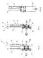
- the device 1 for preparing a stretch of adhesive tape firstly comprises two substantially identical, parallel and superimposed chains 2.
- Each chain 2 forms a plane loop comprising a forward strand 3 and a return strand 4 substantially rectilinear and parallel, and two half-circle portions respectively winding around a drive wheel 5 and a free idling wheel 6 of respective axes 7, 8 substantially parallel.
- the driving wheel 5 is driven by a motor 9, in the direction indicated by the arrow in FIG. 1.
- the terms "upstream” and "downstream” are defined with respect to the direction of movement of the chain 2.
- the motor 9 is for example an electric motor of any type (DC, asynchronous, brushless, etc.). Management of the acceleration and deceleration curves, stop accuracy and nominal speeds is performed via frequency converters or axis cards depending on the selected motor technology.
- the two wheels 5, 6 are placed on a support 10 itself fixed to a base 11 by feet 12.
- the chains 2 are located in vertical planes, but this provision is not limiting.
- a coil 13 of adhesive tape 14 rotatably mounted about the axis 15 of a support 16 fixed to the base 11.
- the axis 15 is substantially parallel to the planes of the chains 2 and orthogonal to the strands go 3 and 4: thus, the adhesive tape 14 will be unwound in a plane substantially parallel to the planes of the chains 2 and in a substantially parallel path to the forward strand 3.
- the adhesive tape 14 may be neutral or have marks ("spotted adhesive"). It may be intended to form a prepared handle, to make a lot, etc. Its width and the length at which the section will be cut may vary depending on the application concerned.
- Each gripper 17 comprises two substantially parallel rods 19, 20 mounted in two separate links of each of the chains 2.
- the rods 19, 20 are here oriented parallel to the axes 7, 8 of the wheels 5, 6 and inserted into the adjacent links of a chain. same chain 2, as shown in Figure 2.
- Each clamp 17 has first and second legs 21, 22 connected by the rods 19, 20, and between which the adhesive tape 14 is intended to be held to be towed.
- the branches 21, 22 extend substantially perpendicular to the rods 19, 20, therefore parallel to the planes of the chains 2, outwardly of the chains 2, and are arranged opposite one another.
- the first branch 21 is intended to be in contact with the adhesive side 23 of the adhesive tape 14. It is fixed with respect to the chains 2, that is to say with respect to the rods 19, 20.
- the first branch 21 comprises at least a roller 24 rotatably mounted about the main axis 25 of said branch 21, orthogonal to the rods 19, 20. It may be a knurled brass roller or freewheels, in particular according to the adhesiveness of the adhesive tape 14 .
- the second branch 22 is intended to be in contact with the smooth side 26 of the adhesive tape 14. It is slidably mounted along the rods 19, 20 relative to the first branch 21.
- One or more springs 27 are arranged between the two branches 21 , 22 and bias the second branch 22 towards its position remote from the first branch 21, that is to say in the open position of the clamp 17.
- the second branch 22 is substantially parallelepipedic and comprises, opposite the first branch 21, an element 28 of flexible material (for example foam or polyurethane).
- the second branch 22 is equipped with rollers 29 with axes substantially parallel to the main axis 25 of the first branch 21.
- the third rod 30 acts as a holding tie, and ensures the parallelism of the two chains 2.
- the device 1 also comprises a system making it possible to cause closure of the clamp 17 and to allow it to be opened, this at given points of the chain 2.
- This system comprises on the one hand a fixed cam (not represented) arranged next to the forward strand 3 from a so-called gripping zone 31, and secondly a movable cam 32 extending in extension of the fixed cam facing the forward strand 3, at least up to a zone known as the release zone 33
- the movable cam 32 driven by a pneumatic actuator, can be moved between an advanced position (by default), in which it is located substantially in the same plane as the fixed cam, and a retracted position.
- the cams are intended to cooperate with the rollers 29 of the gripper 17 during the displacement thereof on the forward strand 3.
- the device 1 comprises a cutting system 34 for cutting the towed adhesive tape 14 to form a separate section of the coil 13.
- the cutting system 34 is located near the forward strand 3, on the traction path of the adhesive tape 14, immediately downstream and as close as possible to the gripping zone 31.
- the cutting system 34 comprises on the one hand a cutting block 35 disposed on the smooth side 26 of the towed adhesive tape 14, and having a transverse knife 36.
- On either side of the knife 36 are disposed support elements, respectively upstream 37 and downstream 38, to ensure the adhesive tape 14 at the time of cutting, as will be seen later.
- the downstream support element 38 may be equipped with a flexible material element (for example foam or polyurethane).
- a pneumatic actuator 39 controls the cutting block 35 to bring it closer to or away from the adhesive tape 14, the cutting block 35 being by default in the retracted position, that is to say away from the adhesive tape 14.
- the cutting system 34 further comprises a counter-cutting block 40 disposed on the adhesive side 23 of the towed adhesive tape 14, and comprising an upstream front finger 41 and a downstream finger 42, spaced from each other and located opposite the support elements 37, 38 of the cutting block 35.
- the counter-cutting block 40 serves to hold the adhesive tape 14 in tension at the time of cutting, on either side of the knife 36 , using the sticky power of the adhesive tape 14.
- the upstream finger 41 is substantially parallelepipedic, while the downstream finger 42 comprises at least one roller 43 rotatably mounted about the main axis of said downstream finger 42, arranged transversely. It can be a knurled brass roller or freewheels.
- a pneumatic actuator 44 drives the countercut block 40 to bring it closer to or away from the adhesive tape 14, the counter-cutting system 40 being by default in the retracted position, that is to say away from the adhesive tape 14 , position in it releases the space required for the passage of the clamp 17, between the cutting block 35 and the counter-cutting block 40.
- the detection modes do not work at the same time, one of them being chosen beforehand at the level of the control system.
- the section of cut tape 14 is held at its end pulled by the clamp 17 located in the release zone 33, and at its other end by the downstream finger 42.
- the adhesive tape 14 unwinding the coil 13, it is maintained at its upstream end by the upstream finger 41.
- the upstream finger 41 being parallelepipedic, it allows a bonding of the adhesive tape 14 on a larger surface than a cylindrical finger, and therefore a better hold.
- the adhesive tape 14 is always held on the reel side pending the arrival of a new clip 17.
- the device 1 can be placed in any position in space, the gravity not risking moving the adhesive tape.
- the opening of the clamp 17 is then controlled by moving the movable cam 32 to its retracted position.
- the adhesive tape 14 remains held at its towed end, by gluing on the first branch 21.
- the section of adhesive tape 14 thus prepared is then transferred to a use station (not shown) in a direction substantially orthogonal to the plane of the towed adhesive tape. During this movement, the adhesive tape 14 is easily detached from the clamp 17 and the downstream finger 42 by causing the rotation of the roller or rollers 24, 43 towards each other. It should be noted that, on the side of the towed end, the adhesive tape 14 is very well held on the first branch 21 of the clamp 17, because it has been well applied to the roller or rollers 24 by crushing the element The gripper 17 must therefore be open to allow the adhesive tape 14 to detach.
- the adhesive tape 14 is only slightly stuck on the downstream finger 42 (generally on a generatrix), and it is therefore not necessary to move the counter-cut block 35 to its retracted position to allow the release of the adhesive tape 14.
- the transfer can for example be performed by a jack system 46, disposed on the smooth side 26 of the adhesive tape 14 (see Figures 5 and 13).
- the traction of the adhesive tape 14 is independent of the movement of the product or products to be equipped with said ribbon, which makes it possible to perform a better controlled bonding, while the products are stopped.
- the chains 2 are then moved again, the clamps 17 thus moving simultaneously to bring the clamp 17 which was waiting on the return strand 4 to the gripping zone 31, while the clamp 17 which has just pulled the adhesive tape 14 being discharged on the return strand 4.
- the stop of the clamp 17 in the gripping zone 31 is controlled by a detection cell.
- the clamp 17 closes in this movement, in contact with the fixed cam, just before the cutting system 34.
- the longitudinal distance between the counter-cutting block 40 and the input of the fixed cam is fixed.
- the adhesive tape 14 coming from the coil 13 is now engaged in the clip 17.
- the device 1 is then in the initial situation described above, and the traction / cutting cycle / movement of the clamps can be repeated.
- the average time of a cycle can be of the order of 0.65 seconds.
- the return of the gripper coming from towing the adhesive tape is operated in masked time, while the other gripper in turn tows the adhesive tape.
- the forward strand 3 materializes the trajectory of the adhesive tape and the possible lengths of traction. This length can be easily parameterized by freezing the positioning of the gripping zone 31 and by providing a plurality of successive moving cams 32 in extension of the fixed cam. According to the active moving cam, the release zone 33 is thus positioned.
- the motorized drum 47 materializes a physical cut between the bobbin winding lever 49 (animated oscillations) and the device 1. It ensures the traction of the adhesive tape from the spool 13 and assists in feeding the adhesive tape to the gripper 17 when it was put into action.
- the motorized drum 47 cash therefore the largest tensile force related to the unwinding of the adhesive tape from the coil 13 (about twice the force measured between the drum and the clamp).
- the primary traction is provided by the drum, the unwinding is performed at the unwinder (by rotation of the spool 13). Between the device 1 and the drum, the primary traction is provided by the gripper 17, unwinding and secondary traction being provided by the motorized drum 47.
- the traction of the adhesive tape 14 by the movement of the clamp 17 on the chains 2 causes the muffle 48 to oscillate at the output of the motorized drum 47 and disengages the detection cell.
- the non-detection of the muffle 48 then triggers the rotation of the motorized drum 47.
- the pulling of the adhesive tape by the drum then oscillates the unwinding lever 49 and disengages the detection cell.
- the non-detection of the unwinding lever 49 then triggers the release of the electromagnetic brake of the unwinder, thus allowing the spool 13 to rotate and the adhesive tape 14 to unfold.
- the traction of the adhesive tape is thus managed by cascading the various actuators. Stopping the unwinding of the coil 13 is obtained not the inverse reaction of each actuator, triggered from the stop of the clamp 17 at the end of the stroke on the forward strand 3, that is to say in the zone of release 33.
Applications Claiming Priority (1)
| Application Number | Priority Date | Filing Date | Title |
|---|---|---|---|
| FR0600230A FR2895984B1 (fr) | 2006-01-11 | 2006-01-11 | Dispositif et procede de preparation d'un troncon de ruban adhesif de longueur souhaitee a partir d'une bobine |
Publications (1)
| Publication Number | Publication Date |
|---|---|
| EP1808393A1 true EP1808393A1 (de) | 2007-07-18 |
Family
ID=37026159
Family Applications (1)
| Application Number | Title | Priority Date | Filing Date |
|---|---|---|---|
| EP20060356147 Withdrawn EP1808393A1 (de) | 2006-01-11 | 2006-12-19 | Vorrichtung und Verfahren zur Vorbereitung eines eine gewünschte Länge aufweisenden Klebebandabschnittes aus einer Spule |
Country Status (3)
| Country | Link |
|---|---|
| US (1) | US20070157777A1 (de) |
| EP (1) | EP1808393A1 (de) |
| FR (1) | FR2895984B1 (de) |
Cited By (1)
| Publication number | Priority date | Publication date | Assignee | Title |
|---|---|---|---|---|
| CN108313799A (zh) * | 2017-12-19 | 2018-07-24 | 芜湖市夏氏世家家具有限公司 | 一种床面包裹装置的输送装置 |
Families Citing this family (3)
| Publication number | Priority date | Publication date | Assignee | Title |
|---|---|---|---|---|
| US8789568B2 (en) | 2010-08-06 | 2014-07-29 | First Solar, Inc. | Tape detection system |
| CN105731143B (zh) * | 2016-03-24 | 2018-06-15 | 宁波敏实汽车零部件技术研发有限公司 | 一种供膜装置 |
| CN112959390B (zh) * | 2021-01-29 | 2022-10-25 | 广东利元亨智能装备股份有限公司 | 柔性物料切割方法、装置、电子设备及计算机存储介质 |
Citations (3)
| Publication number | Priority date | Publication date | Assignee | Title |
|---|---|---|---|---|
| JPS57145756A (en) * | 1981-02-27 | 1982-09-08 | Nippon Steel Metal Prod Co Ltd | Apparatus for withdrawing sheet material |
| US5445053A (en) * | 1994-03-24 | 1995-08-29 | Mima Incorporated | Sheet cutting and placing apparatus, related method, and related package |
| FR2818242A1 (fr) * | 2000-12-14 | 2002-06-21 | Cefma | Installation de fardelage avec pose integree de bande de dechirage |
Family Cites Families (2)
| Publication number | Priority date | Publication date | Assignee | Title |
|---|---|---|---|---|
| US3701299A (en) * | 1971-03-02 | 1972-10-31 | Stumpf Guenter | Apparatus for forming stacks of cloth webs which are cut to length |
| DE2932698C2 (de) * | 1979-08-11 | 1981-03-19 | G. Siempelkamp Gmbh & Co, 4150 Krefeld | Vorrichtung zum Zusammenlegen von Trägermatten und Metallfolienbahnabschnitten im Zuge der Herstellung von Laminatplatten |
-
2006
- 2006-01-11 FR FR0600230A patent/FR2895984B1/fr not_active Expired - Fee Related
- 2006-12-19 EP EP20060356147 patent/EP1808393A1/de not_active Withdrawn
- 2006-12-28 US US11/646,562 patent/US20070157777A1/en not_active Abandoned
Patent Citations (3)
| Publication number | Priority date | Publication date | Assignee | Title |
|---|---|---|---|---|
| JPS57145756A (en) * | 1981-02-27 | 1982-09-08 | Nippon Steel Metal Prod Co Ltd | Apparatus for withdrawing sheet material |
| US5445053A (en) * | 1994-03-24 | 1995-08-29 | Mima Incorporated | Sheet cutting and placing apparatus, related method, and related package |
| FR2818242A1 (fr) * | 2000-12-14 | 2002-06-21 | Cefma | Installation de fardelage avec pose integree de bande de dechirage |
Non-Patent Citations (1)
| Title |
|---|
| PATENT ABSTRACTS OF JAPAN vol. 006, no. 249 (M - 177) 8 December 1982 (1982-12-08) * |
Cited By (1)
| Publication number | Priority date | Publication date | Assignee | Title |
|---|---|---|---|---|
| CN108313799A (zh) * | 2017-12-19 | 2018-07-24 | 芜湖市夏氏世家家具有限公司 | 一种床面包裹装置的输送装置 |
Also Published As
| Publication number | Publication date |
|---|---|
| FR2895984B1 (fr) | 2008-04-11 |
| FR2895984A1 (fr) | 2007-07-13 |
| US20070157777A1 (en) | 2007-07-12 |
Similar Documents
| Publication | Publication Date | Title |
|---|---|---|
| EP0270419B1 (de) | Handgesteuerte Bandumwicklungsvorrichtung von Stücken, wie namentlich Kabelbäumen | |
| FR2612879A1 (fr) | Appareil d'alimentation en un materiau sous forme de film | |
| FR2617800A1 (fr) | Appareil chargeur de bande pour une machine a emballer | |
| EP1808393A1 (de) | Vorrichtung und Verfahren zur Vorbereitung eines eine gewünschte Länge aufweisenden Klebebandabschnittes aus einer Spule | |
| EP3156356B1 (de) | Zuführung für verpackvorgänge mit schrumpffolie | |
| EP1577219A1 (de) | Vorrichtung zum Anbringen eines Tragegriffs | |
| WO2006053909A1 (fr) | Machine automatique pour la formation d'un noeud a l'aide d'une ficelle en extremite d'une gaine tubulaire en vue de l'obturer par constriction sous l'effet du serrage du noeud | |
| FR2510535A1 (fr) | Distributeur-applicateur de ruban d'assemblage | |
| FR2484979A1 (fr) | Procede et appareil d'assemblage de matiere en feuille, notamment pour alimenter en continu des imprimantes rapides | |
| EP2112106B1 (de) | Verfahren und Vorrichtung zum Stoßschneiden und -verkleben für Rundschälmaschine | |
| EP0921074B1 (de) | Verfahren und Vorrichtung zum Zusammenfügen von ausgerichteten Gegenständen mittels Klebebändern | |
| FR2823190A1 (fr) | Procede pour recharger une fardeleuse a l'aide d'un film plastique, et fardeleuse mettant en oeuvre le procede | |
| FR2586663A1 (fr) | Dispositif pour alimenter et couper une bande d'etiquettes | |
| EP0304465A1 (de) | Vorrichtung zum verknoten eines flexiblen bandes | |
| EP1251094B1 (de) | Bewegungsvorrichtung für ein Klebeband | |
| FR2552408A1 (fr) | Dispositif de fixation de troncons de ruban sur des morceaux de tissu | |
| FR2772000A1 (fr) | Procede et dispositif pour reunir en lots des paquets en file continue au moyen de troncons de bandes adhesives | |
| FR2678238A1 (fr) | Machine pour la pose de poignees sur des colis. | |
| EP2374719B1 (de) | Anlage zum Aufbringen von Klebesegmenten auf durchlaufende Pakete | |
| EP1328440A1 (de) | Vorrichtung zum bündeln von gegenständen, insbesonderes stabförmige, mittels einem klebestreifen | |
| FR2557491A1 (fr) | Machine pour la coupe et la pose de troncons de ruban souple | |
| FR2518977A1 (fr) | Dispositif pour plier en forme de z des segments de feuille continue tubulaire ou non tubulaire | |
| FR2880329A1 (fr) | Procede et dispositif de raccordement de deux gaines tubulaires aplaties dans une machine de pose de manchons sur des objets en defilement | |
| BE815807R (fr) | Dispositif destine a la fixation de l'extremite libre d'un rouleau de materiau audit rouleau | |
| FR91784E (de) |
Legal Events
| Date | Code | Title | Description |
|---|---|---|---|
| PUAI | Public reference made under article 153(3) epc to a published international application that has entered the european phase |
Free format text: ORIGINAL CODE: 0009012 |
|
| AK | Designated contracting states |
Kind code of ref document: A1 Designated state(s): AT BE BG CH CY CZ DE DK EE ES FI FR GB GR HU IE IS IT LI LT LU LV MC NL PL PT RO SE SI SK TR |
|
| AX | Request for extension of the european patent |
Extension state: AL BA HR MK YU |
|
| 17P | Request for examination filed |
Effective date: 20071214 |
|
| AKX | Designation fees paid |
Designated state(s): DE ES FR IT PT TR |
|
| RAP1 | Party data changed (applicant data changed or rights of an application transferred) |
Owner name: CEFMA TECHNOLOGY |
|
| STAA | Information on the status of an ep patent application or granted ep patent |
Free format text: STATUS: THE APPLICATION IS DEEMED TO BE WITHDRAWN |
|
| 18D | Application deemed to be withdrawn |
Effective date: 20120703 |