EP1804484A1 - Vorrichtung, Verfahren und System zur Bildverarbeitung und Informationsaufzeichnungsmedium - Google Patents
Vorrichtung, Verfahren und System zur Bildverarbeitung und Informationsaufzeichnungsmedium Download PDFInfo
- Publication number
- EP1804484A1 EP1804484A1 EP06256612A EP06256612A EP1804484A1 EP 1804484 A1 EP1804484 A1 EP 1804484A1 EP 06256612 A EP06256612 A EP 06256612A EP 06256612 A EP06256612 A EP 06256612A EP 1804484 A1 EP1804484 A1 EP 1804484A1
- Authority
- EP
- European Patent Office
- Prior art keywords
- information
- image
- additional information
- image processing
- additional
- Prior art date
- Legal status (The legal status is an assumption and is not a legal conclusion. Google has not performed a legal analysis and makes no representation as to the accuracy of the status listed.)
- Withdrawn
Links
- 238000003672 processing method Methods 0.000 title claims description 20
- 238000000605 extraction Methods 0.000 claims abstract description 45
- 238000000034 method Methods 0.000 claims description 68
- 230000000873 masking effect Effects 0.000 claims description 13
- 238000004590 computer program Methods 0.000 claims description 2
- 230000000694 effects Effects 0.000 claims 2
- 230000005540 biological transmission Effects 0.000 description 110
- 230000008569 process Effects 0.000 description 37
- 230000004044 response Effects 0.000 description 17
- 238000010586 diagram Methods 0.000 description 16
- 239000000284 extract Substances 0.000 description 16
- 238000000926 separation method Methods 0.000 description 7
- 238000001514 detection method Methods 0.000 description 4
- 230000010365 information processing Effects 0.000 description 4
- 238000002955 isolation Methods 0.000 description 4
- 230000002093 peripheral effect Effects 0.000 description 4
- 238000012986 modification Methods 0.000 description 3
- 230000004048 modification Effects 0.000 description 3
- 239000000470 constituent Substances 0.000 description 2
- 238000006243 chemical reaction Methods 0.000 description 1
- 239000003086 colorant Substances 0.000 description 1
- 230000006870 function Effects 0.000 description 1
- 230000000717 retained effect Effects 0.000 description 1
Images


Classifications
-
- H—ELECTRICITY
- H04—ELECTRIC COMMUNICATION TECHNIQUE
- H04N—PICTORIAL COMMUNICATION, e.g. TELEVISION
- H04N1/00—Scanning, transmission or reproduction of documents or the like, e.g. facsimile transmission; Details thereof
- H04N1/32—Circuits or arrangements for control or supervision between transmitter and receiver or between image input and image output device, e.g. between a still-image camera and its memory or between a still-image camera and a printer device
- H04N1/32101—Display, printing, storage or transmission of additional information, e.g. ID code, date and time or title
-
- H—ELECTRICITY
- H04—ELECTRIC COMMUNICATION TECHNIQUE
- H04N—PICTORIAL COMMUNICATION, e.g. TELEVISION
- H04N1/00—Scanning, transmission or reproduction of documents or the like, e.g. facsimile transmission; Details thereof
- H04N1/00127—Connection or combination of a still picture apparatus with another apparatus, e.g. for storage, processing or transmission of still picture signals or of information associated with a still picture
- H04N1/00204—Connection or combination of a still picture apparatus with another apparatus, e.g. for storage, processing or transmission of still picture signals or of information associated with a still picture with a digital computer or a digital computer system, e.g. an internet server
- H04N1/00244—Connection or combination of a still picture apparatus with another apparatus, e.g. for storage, processing or transmission of still picture signals or of information associated with a still picture with a digital computer or a digital computer system, e.g. an internet server with a server, e.g. an internet server
-
- H—ELECTRICITY
- H04—ELECTRIC COMMUNICATION TECHNIQUE
- H04N—PICTORIAL COMMUNICATION, e.g. TELEVISION
- H04N1/00—Scanning, transmission or reproduction of documents or the like, e.g. facsimile transmission; Details thereof
- H04N1/0035—User-machine interface; Control console
- H04N1/00352—Input means
- H04N1/00355—Mark-sheet input
- H04N1/00358—Type of the scanned marks
-
- H—ELECTRICITY
- H04—ELECTRIC COMMUNICATION TECHNIQUE
- H04N—PICTORIAL COMMUNICATION, e.g. TELEVISION
- H04N1/00—Scanning, transmission or reproduction of documents or the like, e.g. facsimile transmission; Details thereof
- H04N1/0035—User-machine interface; Control console
- H04N1/00352—Input means
- H04N1/00355—Mark-sheet input
- H04N1/00368—Location of the scanned marks
- H04N1/00374—Location of the scanned marks on the same page as at least a part of the image
-
- H—ELECTRICITY
- H04—ELECTRIC COMMUNICATION TECHNIQUE
- H04N—PICTORIAL COMMUNICATION, e.g. TELEVISION
- H04N1/00—Scanning, transmission or reproduction of documents or the like, e.g. facsimile transmission; Details thereof
- H04N1/32—Circuits or arrangements for control or supervision between transmitter and receiver or between image input and image output device, e.g. between a still-image camera and its memory or between a still-image camera and a printer device
- H04N1/32101—Display, printing, storage or transmission of additional information, e.g. ID code, date and time or title
- H04N1/32144—Display, printing, storage or transmission of additional information, e.g. ID code, date and time or title embedded in the image data, i.e. enclosed or integrated in the image, e.g. watermark, super-imposed logo or stamp
-
- H—ELECTRICITY
- H04—ELECTRIC COMMUNICATION TECHNIQUE
- H04N—PICTORIAL COMMUNICATION, e.g. TELEVISION
- H04N2201/00—Indexing scheme relating to scanning, transmission or reproduction of documents or the like, and to details thereof
- H04N2201/0008—Connection or combination of a still picture apparatus with another apparatus
- H04N2201/0034—Details of the connection, e.g. connector, interface
- H04N2201/0037—Topological details of the connection
- H04N2201/0039—Connection via a network
-
- H—ELECTRICITY
- H04—ELECTRIC COMMUNICATION TECHNIQUE
- H04N—PICTORIAL COMMUNICATION, e.g. TELEVISION
- H04N2201/00—Indexing scheme relating to scanning, transmission or reproduction of documents or the like, and to details thereof
- H04N2201/0077—Types of the still picture apparatus
- H04N2201/0094—Multifunctional device, i.e. a device capable of all of reading, reproducing, copying, facsimile transception, file transception
-
- H—ELECTRICITY
- H04—ELECTRIC COMMUNICATION TECHNIQUE
- H04N—PICTORIAL COMMUNICATION, e.g. TELEVISION
- H04N2201/00—Indexing scheme relating to scanning, transmission or reproduction of documents or the like, and to details thereof
- H04N2201/32—Circuits or arrangements for control or supervision between transmitter and receiver or between image input and image output device, e.g. between a still-image camera and its memory or between a still-image camera and a printer device
- H04N2201/3201—Display, printing, storage or transmission of additional information, e.g. ID code, date and time or title
- H04N2201/3225—Display, printing, storage or transmission of additional information, e.g. ID code, date and time or title of data relating to an image, a page or a document
- H04N2201/3242—Display, printing, storage or transmission of additional information, e.g. ID code, date and time or title of data relating to an image, a page or a document of processing required or performed, e.g. for reproduction or before recording
-
- H—ELECTRICITY
- H04—ELECTRIC COMMUNICATION TECHNIQUE
- H04N—PICTORIAL COMMUNICATION, e.g. TELEVISION
- H04N2201/00—Indexing scheme relating to scanning, transmission or reproduction of documents or the like, and to details thereof
- H04N2201/32—Circuits or arrangements for control or supervision between transmitter and receiver or between image input and image output device, e.g. between a still-image camera and its memory or between a still-image camera and a printer device
- H04N2201/3201—Display, printing, storage or transmission of additional information, e.g. ID code, date and time or title
- H04N2201/3225—Display, printing, storage or transmission of additional information, e.g. ID code, date and time or title of data relating to an image, a page or a document
- H04N2201/3249—Display, printing, storage or transmission of additional information, e.g. ID code, date and time or title of data relating to an image, a page or a document data relating to a linked page or object, e.g. hyperlink
-
- H—ELECTRICITY
- H04—ELECTRIC COMMUNICATION TECHNIQUE
- H04N—PICTORIAL COMMUNICATION, e.g. TELEVISION
- H04N2201/00—Indexing scheme relating to scanning, transmission or reproduction of documents or the like, and to details thereof
- H04N2201/32—Circuits or arrangements for control or supervision between transmitter and receiver or between image input and image output device, e.g. between a still-image camera and its memory or between a still-image camera and a printer device
- H04N2201/3201—Display, printing, storage or transmission of additional information, e.g. ID code, date and time or title
- H04N2201/3269—Display, printing, storage or transmission of additional information, e.g. ID code, date and time or title of machine readable codes or marks, e.g. bar codes or glyphs
- H04N2201/327—Display, printing, storage or transmission of additional information, e.g. ID code, date and time or title of machine readable codes or marks, e.g. bar codes or glyphs which are undetectable to the naked eye, e.g. embedded codes
-
- H—ELECTRICITY
- H04—ELECTRIC COMMUNICATION TECHNIQUE
- H04N—PICTORIAL COMMUNICATION, e.g. TELEVISION
- H04N2201/00—Indexing scheme relating to scanning, transmission or reproduction of documents or the like, and to details thereof
- H04N2201/32—Circuits or arrangements for control or supervision between transmitter and receiver or between image input and image output device, e.g. between a still-image camera and its memory or between a still-image camera and a printer device
- H04N2201/3201—Display, printing, storage or transmission of additional information, e.g. ID code, date and time or title
- H04N2201/3271—Printing or stamping
Definitions
- the present invention relates to an image processing device, an image processing method, an image processing system, and an information recording medium, particularly, to an image processing device, an image processing method, an image processing system, and an information recording medium which performs image processing based on additional information extracted from an image.
- reference 1 Japanese Laid-Open Patent Application No. 11-119597 discloses a copier in which code information added at a certain location in an object image read by a reader is identified, and copy conditions corresponding to the code information are read out from a storage unit where plural copy conditions are stored, and the read-out copy conditions are set as the copy conditions when copying the above object image.
- Japanese Laid-Open Patent Application No. 2004-343564 discloses a facsimile machine which includes a two-dimensional bar code printing unit for recording, in a header of a document, various kinds of information input at the time of transmission, such as transmission destination, polling, broadcasting, number of documents, and a scanner for reading the document with two-dimensional bar code printed thereon.
- the code added in an image is either a preset bar code or a two-dimensional code, and the amount of information able to be carried by these kinds of codes is limited.
- information may be added to an object image by embedding the information into a dot pattern with some known methods, and this dot pattern may be added to the object image. With this technique, quite a large amount of information can be added to the object image.
- information is added to an image by specific methods, and other methods for adding information are not considered.
- the devices carry out a certain number of processes specified in advance, such as copying or facsimile transmission, and the conditions under which the devices carry out the processing are designated.
- the techniques disclosed in reference 1 and reference 2 do not consider multiple processing and setting of multiple processing conditions, which are performed in a MPF (Multi Functional Peripheral) supporting multiple processes, or a PC (personal computer).
- MPF Multi Functional Peripheral
- PC personal computer
- An embodiment of the present invention may solve one or more problems of the related art.
- a preferred embodiment of the present invention may provide an image processing device supporting multiple processes and multiple information addition methods, which is able to select one of plural processes and specify conditions of the selected process when acquiring, from image additional information, specific operations and conditions of the selected process, or additional information, and is more user-friendly and is of high versatility.
- an image processing device comprising:
- an image processing method comprising:
- a computer program product for use in an image processing device, comprising:
- additional information means information additionally embedded in the image information.
- the additionally embedded information can be converted into specified codes or patterns readable by a reading device, and it may be a pattern not visually perceivable by human eyes.
- the additional information may be a certain pattern formed by two-dimensional codes, such as, a bar code or a QR code, dots or a dot combination, or characters having modulated edge shapes, or modulated background colors.
- the method of adding the additional information is not limited to the above examples, but may have various modifications depending on devices or operators.
- the image information extracted from an manuscript image corresponds to information expressed on the manuscript image, for example, documents or drawings created by using applications, such as, "WORD” (a registered trademark), or "POWER POINT” (a registered trademark), and may include any kind of information except for the above mentioned additional information.
- WORD a registered trademark
- POWER POINT a registered trademark
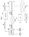
- FIG. 1 is a block diagram illustrating a configuration of an image processing system according to a first embodiment of the present invention.
- the image processing system shown in FIG. 1 includes an information adding device 1000, an image processing device 2000, a reading device 2100, which is connected to the image processing device 2000, an MFP (multi functional peripheral) 501, and a storage device 502.
- an information adding device 1000 an image processing device 2000
- a reading device 2100 which is connected to the image processing device 2000
- an MFP (multi functional peripheral) 501 an MFP (multi functional peripheral) 501
- the information adding device 1000 and the image processing device 2000 are connected through a network 70a, the image processing device 2000 is connected to the reading device 2100, and is connected to the MFP 501 and the storage device 502 through a network 70b.
- the information adding device 1000 acquires image information 1 and additional information 2, and prints a manuscript document 900, which is obtained by adding the additional information 2 into the image information 1, and outputs manuscript image data 910a, which is also obtained by adding the additional information 2 into the image information 1.
- each of the manuscript document 900 and the manuscript image data 910a includes the image information 1 and the additional information 2.
- the image processing device 2000 receives the manuscript image data 910a through the network 70a; the reading device 2100, for example, a scanner, reads the manuscript document 900 and obtains manuscript image data 910b; the manuscript image data 910b is input to the image processing device 2000. After receiving the manuscript image data 910a and 910b, the image processing device 2000 carries out appropriate processing.
- the image processing device 2000 may receive the manuscript image data 910a and 910b from a storage medium, such as a floppy disk (not illustrated) or a SD card (registered trademark) (not illustrated).
- a storage medium such as a floppy disk (not illustrated) or a SD card (registered trademark) (not illustrated).
- the network 70a and the network 70b may be the Internet or an intranet.
- the network 70a and the network 70b are shown as different networks in FIG. 1, but the network 70a and the network 70b may be the same network.
- the image processing device 2000 extracts the image information 1 and the additional information 2 from the manuscript image data 910a and 910b, and performs processing on the additional information 2.
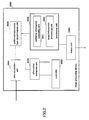
- FIG. 2 is a block diagram illustrating a configuration of the image processing device 2000 according to the present embodiment.
- the image processing device 2000 is formed from a versatile computer, or a printer or an MFP installed with application.
- the image processing device 2000 includes a data acquisition unit 2010, an additional information type determination unit 2020, an information extraction unit 2030, a processing unit 2040, a controller 2050, and an output unit 2060.
- the data acquisition unit 2010 acquires the manuscript image data 910a and 910b, which include the image information 1 and the additional information 2.
- the data acquisition unit 2010 may be integrated with the reading device 2100, or may be used as an interface (below, abbreviated as "I/F" where necessary) for inputting image data, or may be a device for reading manuscript image data stored in a storage device (not illustrated) of the reading device 2100.
- the additional information type determination unit 2020 determines the type and attribute of the additional information when the additional information is readable, and outputs the determination results to the information extraction unit 2030 and the processing unit 2040.
- the additional information may be a bar code, a two-dimensional code, such as, a QR code, a dot pattern, modulation of the shape of a character edge, or conversion of frequency in a high frequency region of the character edge.
- the mode of the additional information is not limited to the above examples.
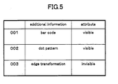
- the attribute of the additional information may be information indicating whether the additional information is visually perceivable by human eyes. For example, if usually presence of the additional information does not bother a user, and the additional information is visually perceivable only when the user pays close attention to it, this additional information is regarded to be not visually perceivable.
- the bar code, the two-dimensional code, such as, the QR code, and the dot pattern are treated as modes readable by a reading device and visually perceivable by human eyes, and modulation of the shape of the character edge, or information embedding in terms of a frequency region are treated to be modes readable by a reading device but not visually perceivable by human eyes.
- the information extraction unit 2030 extracts the additional information 2 based on the determination results from the additional information type determination unit 2020.
- the processing unit 2040 performs processing on the image information 1 corresponding to the type and attribute of the additional information. Therefore, it is possible to improve accuracy of extraction of the image information 1 and the additional information 2, and increase speed of image processing.
- the processing unit 2040 includes an additional information separation part 2041, and an image information processing part 2042.
- the additional information separation part 2041 separates the image information 1 and the additional information 2 in the manuscript image data in response to the determination results from the additional information type determination unit 2020, that is, the type and attribute of the additional information.
- the manuscript image data correspond to original image data which include the manuscript image data 910a, the manuscript image data 910b, and other image data, with the image information 1 and the additional information 2 embedded.
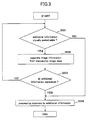
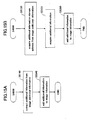
- FIG. 3 is a flowchart illustrating operations of the processing unit 2040 according to the present embodiment.
- step S301 the additional information separation part 2041 determines whether the additional information 2 is visually perceivable by human eyes. For example, the additional information separation part 2041 may made this determination based on the determination results from the additional information type determination unit 2020. If the additional information 2 is visually perceivable by human eyes, the routine proceeds to step S302, otherwise, the routine proceeds to step S304.
- step S302 the additional information separation part 2041 separates the image information 1 and the additional information 2 from the manuscript image data, and extracts the image information 1. Since this step is not executed if the additional information 2 is not visually perceivable by human eyes, as determined in step S301, the processing speed can be increased.
- step S302 If the step S302 is omitted, that is, if the image information 1 and the additional information 2 from the manuscript image data are not separated, the subsequent processing would be performed on the manuscript image data including the additional information 2 but not on the image information 1 only, consequently, various processes are executed on both of the additional information 2 and the image information 1, which additional information 2 is not necessary to an non-specialist user. Therefore, by executing step S302, it is possible to provide a user-friendly image processing device. The operations in step S302 are described in detail below.
- step S303 it is determined whether the additional information separation part 2041 completely separated and removed the additional information 2 in the manuscript image data, and obtained the image information 1 without the additional information 2.
- step S304 If the additional information separation part 2041 obtained the image information 1 without the additional information 2, the routine proceeds to step S304, otherwise, if the image information 1 still includes the additional information 2, the routine returns to step S301.
- step S304 the image information processing part 2042 performs processing on the image information 1 in response to the additional information 2 extracted by the information extraction unit 2030.
- the image information processing part 2042 performs the processing on the manuscript image data in response to the additional information 2 extracted by the information extraction unit 2030.
- the controller 2050 controls the processing unit 2040 to perform processing in accordance with the additional information 2 extracted by the information extraction unit 2030. Therefore, the image information 1 is processed in response to the additional information 2. In other words, the controller 2050 and the image information processing part 2042 implements processing, on the image information 1, defined by the additional information 2.
- the output unit 2060 outputs the image information 1 based on the processing defined by the additional information 2.
- the constituent elements of the image processing device 2000 may be implemented by either hardware (such as electric circuits), or software.
- the CPU of a computer reads out and executes relevant programs to perform operations shown in FIG. 4A and FIG. 4B.
- These programs may be stored beforehand in a not-illustrated storage device, such as a ROM (Read Only Memory), or a hard disk. Alternatively, these programs may be downloaded through a network.
- the data in a storage device such as a CD-ROM, and a SD card (registered trademark), may be read out and stored in the storage device of the image processing device 2000.
- FIG. 4A and FIG. 4B are flowcharts illustrating operations of the image processing device 2000 according to the present embodiment.
- FIG. 4A illustrates operations of extracting the additional information 2 after acquiring the type of the additional information 2 of the manuscript image data
- FIG. 4B illustrates operations of acquiring the type of the additional information 2 after the additional information 2 is extracted by a known method.
- step S401 the data acquisition unit 2010 obtains the manuscript image data, and expands the manuscript image data in a memory of the image processing device 2000.
- step S402 the additional information type determination unit 2020 determines whether the manuscript image data obtained in step 401 include the additional information 2. If the manuscript image data include the additional information 2, the routine proceeds to step S403, otherwise, the routine ends.
- the additional information type determination unit 2020 determines the type and attribute of the additional information. For example, a display may be provided to show a screen prompting the user to input the type of the additional information, and data input by the user may be used as the type of the additional information.
- a display may be provided to show a screen prompting the user to input the type of the additional information, and data input by the user may be used as the type of the additional information.
- FIG. 5 is a table illustrating an association table between the additional information 2 and the attribute of the additional information 2.
- the association table as shown in FIG. 5 is retained in a RAM, and the additional information type determination unit 2020 may refer to table in the RAM to determine the attribute of the additional information.
- step S404 the information extraction unit 2030 extracts the additional information 2 from the input manuscript image data.
- the additional information 2 is extracted based on the type of the additional information 2. It should be noted that the method of extracting the additional information 2 is well-known, and explanation of it is omitted.
- step S405 it is determined whether the information extraction unit 2030 extracted all of the additional information 2 in the input manuscript image data. If all of the additional information 2 is extracted, the routine proceeds to step S406, if there is still some additional information un-extracted, the routine returns to step S403. It should be noted that if the number of the pieces of the additional information 2 in the input manuscript image data is predetermined, step S405 can be omitted.
- step S406 the processing unit 2040 extracts the image information 1 from the manuscript image data.
- step S407 the processing unit 2040 performs processing on the extracted image information 1 corresponding to the additional information 2.
- step S401 to step S407 the image information 1 in the manuscript image data is processed in response to the additional information 2 extracted from the manuscript image data.
- step S503 and step 504 are different from step S403 and step 404. Below, only these two steps are explained.
- step S503 the information extraction unit 2030 attempts to extract the additional information 2 by all available means.
- step S504 the additional information type determination unit 2020 determines the type and attribute of the extracted additional information 2 based on the determination results of the additional information obtained in step S503.
- processing in the additional information type determination unit 2020 may be omitted.
- the image information 1 in the manuscript image data is processed in response to the preset additional information 2.
- the additional information 2 is a bar code, or a two-dimensional code, such as a QR code
- template matching is performed for the input manuscript image data by using a template of a bar code or a two-dimensional code, which template is stored in a storage device, such as a RAM of the image processing device 2000, thereby, obtaining similarity.
- a storage device such as a RAM of the image processing device 2000
- this region is identified to be a bar code, or a two-dimensional code, like a QR code.
- the pixel value of the region identified to be a bar code are transformed into the pixel value of the background region of the manuscript image data, thereby the image of the additional information 2 is removed from the manuscript image data, and the image information 1 is obtained from the manuscript image data.
- the pixel value of the target region be transformed into the value of white pixels.
- a background color extraction means may be provided to extract the pixel value of the background of the manuscript image data, and the pixel value of the target region can be transformed into the extracted background pixel value, thereby the image of the additional information 2, like a bar code, is removed from the manuscript image data, and the image information 1 is obtained from the manuscript image data.
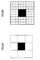
- FIG. 6A and FIG. 6B are diagrams illustrating a method of removing a dot pattern additional information including isolated pixels.
- an isolated pixel is detected from the input manuscript image data.
- an isolated pixel is extracted by determining whether eight pixels adjacent to a target pixel have the same pixel value.
- FIG. 6A it is illustrated that one pixel is used for isolation detection (in other words, in unit of one pixel), and in FIG. 6B, it is illustrated that nine pixels are used for isolation detection (in other words, in unit of nine pixels), however, the present embodiment is not limited to this.
- a number of pixels stored in a RAM or other storage device can be used for isolation detection.
- these pixels having the preset values can be used for isolation detection.
- a connected pixel component can be extracted from the manuscript image data, and when the area or the diameter of the extracted connected pixel component is less than a preset threshold value, the connected pixel component is regarded as the image of the additional information 2, which is formed by a specified pattern expressed by dots or a combination of dots.
- the pixel value of the extracted isolated pixel is transformed into the pixel value of the background region of the manuscript image data, thereby the image of the additional information 2, which is formed by a specified pattern expressed by dots or a combination of dots, is removed from the manuscript image data, and the image information 1 is obtained from the manuscript image data.
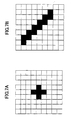
- FIG. 7A and FIG. 7B are diagrams illustrating the method of removing the dot pattern additional information including a dot combination.
- a pattern expressed by a dot combination is not a square, as shown in FIG. 6A and FIG. 6B.
- the following processes can be executed.
- a dot combination pattern stored in a storage device like a RAM, is read out, and it is determined whether a pattern equal or similar to the dot combination pattern read out from the RAM exists in the input manuscript image data. If a pattern the same or similar to the dot combination pattern read out from the RAM exists in the input manuscript image data, the pixel value of the existing pattern in the manuscript image data is transformed into the pixel value of the background region of the manuscript image data, thereby the image of the additional information 2, which is formed from a dot combination pattern, is removed from the manuscript image data, and the image information 1 is obtained from the manuscript image data.
- a background color extraction means may be provided to carry out the above processing.
- a connected pixel component can be extracted from the manuscript image data, and when the area or the diameter of the extracted connected pixel component is less than a preset threshold value, the connected pixel component is regarded as the image of the additional information 2, which is formed by a specified pattern expressed by dots or a combination of dots.
- the pixel value of the extracted isolated pixel is transformed into the pixel value of the background region of the manuscript image data, thereby the image of the additional information 2, which is formed by a specified pattern expressed by dots or a combination of dots, is removed from the manuscript image data, and the image information 1 is obtained from the manuscript image data.
- the above processing can be made using these pixels having the preset values.
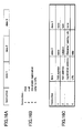
- FIG. 8A through FIG. 8C are data tables illustrating examples of a data structure of the additional information 2.
- FIG. 8A is a table illustrating an example in which the additional information 2 includes a series of variables of a given byte-length.
- the first variable represents "instruction”
- the following variables represent information necessary when executing the instruction.
- FIG. 8B is a table illustrating that the "instruction" variable is expressed by a binary or ASCII variable.
- the "instruction" variable equals "1".
- FIG. 8C is a table illustrating the meaning of the variables following the variable "instruction”.
- the "instruction” variable equals "1"
- the corresponding facsimile number of the recipient is assigned to the "data 1" variable.
- the "instruction” variable equals "5"
- the corresponding region information is assigned to the "data 1" variable
- the data of the masking method is assigned to the "data 2" variable.
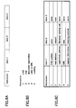
- FIG. 9 is a data tables illustrating examples of the region information assigned to the "data 1" and the masking method assigned to the "data 2" variable.
- each region ID is associated with a quantity "start point - end point (region information)", and a quantity “processing method”.
- the quantity "start point - end point (region information)” indicates coordinates of a region having the corresponding region ID.
- all of the regions are defined to be rectangle, and, for example, the coordinates of the left-bottom vertex and the right-top vertex are assigned to the quantity "start point - end point (region information)", thereby, defining the target region.
- the quantity "processing method” is information for specifying the masking method, such as filling or using of desired patterns. In the table in FIG. 9, shading or filling is specified for each region.
- the image processing device 2000 may determine the specific instruction based on the additional information 2 extracted by the information extraction unit 2030.
- the processing in response to this additional information 2 is identified to be transmitting the image information 1 by facsimile, and in response to this information, the image information 1 is transmitted by facsimile.
- the additional information 2 is merely a character string including "@”
- the character string including "@” can be identified as an email address, and the processing in response to this additional information 2 is identified to be sending the image information 1, by email, to an address specified by the character string including "@”; in response to this information, a mail transmission processing is carried out.
- the mail transmission processing may be any processing for transmitting a mail, for example, send the image information 1 by email, or display a mail-editing screen showing a text with the image information 1 being inserted, or register the image information 1 as an attachment of an email, or a combination of the above processes.
- the additional information 2 includes both a character string including "@”, and another character string
- the character string including "@” can be identified as an email address, and the other character string can be identified as a title of an email.
- the additional information 2 is a string of alphabetic characters including the symbols "/”, or " ⁇ "
- the alphabetic character string can be identified as an address of a location for registering the image information 1, accordingly, the image information 1 is stored at this address.
- each additional information 2 may correspond to plural processing.
- the processing in response to this additional information 2 may include both of transmitting the image information 1 by facsimile and masking.
- the processing in response to this additional information 2 may include both of transmitting the image information 1 by facsimile and transmitting an email.
- FIG. 10 is a block diagram illustrating a configuration of an image processing system according to a second embodiment of the present invention.
- an information embedding device 100 outputs recording information 90
- an image processing device 200 reads the recording information 90 to carry out processing.
- the information embedding device 100 and the image processing device 200 are connected by a network 70 and a local bus 80, but the information embedding device 100 and the image processing device 200 may be connected by either the network 70 or the local bus 80, or the connection between the information embedding device 100 and the image processing device 200 may be omitted.
- the information embedding device 100 and the image processing device 200 may be integrated to serve as an information embedding and image processing device.
- the information embedding device 100 acquires image data of an image 1 (the same as the image information 1 in the first embodiment) and additional information 2, and embeds the additional information 2, or coded data of the additional information 2 into the image data of the image 1 to generate the recording information 90.
- the recording information 90 includes image information 91, which is the image data of the image 1, and image additional information 92, which is the additional information 2, or the coded data of the additional information 2.
- the information embedding device 100 corresponds to the information adding device 1000
- the image processing device 200 corresponds to the image processing device 2000
- the recording information 90 corresponds to the manuscript image data 910a and the manuscript document 900
- the image reading unit 210 corresponds to the data acquisition unit 2010
- the image additional information acquisition unit 230 corresponds to the information extraction unit 2030
- the processing unit 240 corresponds to the processing unit 2040.
- the additional information 2 can be embedded by the following methods. For example, a bar code or a QR code may be produced from the additional information 2, and the bar code or the QR code may be embedded. Alternatively, data of the additional information 2 may be encoded and made invisible and embedded. As for the methods of making the additional information 2 invisible, the additional information 2 may be embedded into a dot pattern, and the dot pattern may be added as background of the image 1. Alternatively, the additional information 2 may be embedded into the image 1 as a digital watermark.
- the additional information 2 invisible, which is the image additional information 92 included in the generated recording information 90, it is possible to prevent the additional information 2 from being viewed by others when the additional information 2 is used in processing in the image processing device 200, and when the recording information 90 is read into the image processing device 200.
- the image processing device 200 reads the recording information 90 and executes certain processes in response to the recording information 90.
- the image processing device 200 is connected to a facsimile machine 40, a network 50, and a storage device 60.
- the recording information 90 may be input to the image processing device 200 when an image printed on a piece of paper or other media is read by the image processing device 200; alternatively, the recording information 90 may be input to the image processing device 200 from the information embedding device 100 through the network 70 or the local bus 80.
- the image processing device 200 extracts the image information 91 and the image additional information 92 from the recording information 90, and executes certain processes in response to the image additional information 92.
- FIG. 11 is a block diagram illustrating a configuration of the image processing device 200 according to the present embodiment.
- the image processing device 200 which is connected to the facsimile machine 40 and other devices, reads the recording information 90 and outputs certain signals to the facsimile machine 40 and other devices.
- the image processing device 200 is connected to the facsimile machine 40, the network 50, and the storage device 60 through a facsimile I/F 49, a network I/F 59, and a storage device I/F 69, respectively.
- the image processing device 200 includes a processing unit 240, an image reading unit 210, an image additional information acquisition unit 230, and an image information acquisition unit 220.
- the processing unit 240 selects one of plural processes to be executed by the image processing device 200 and executes the process.
- the processing unit 240 includes a multiple process execution unit 250 and a process determination unit 290.
- the multiple process execution unit 250 serves as a main processing section of plural processes to be executed by the image processing device 200, and includes a transmission information generation unit 260, a storage information generation unit 270, and an additional information acquisition unit 280.
- the transmission information generation unit 260 generates transmission information used for transmitting the image information 91, and includes an image transmission information extraction part 261, an address acquisition part 262, an image transmission information acquisition part 263, and a transmission document generation part 264.
- the transmission information generated by the transmission information generation unit 260 is in correspondence to a transmission device designated by the image additional information 92, and can be used in any kind of transmission device, such as a transmission device, a facsimile transmission device, and others.
- the transmission information may include a transmission address to which the image information 91 is to be transmitted, a title of the image information 91 to be transmitted, or an address of the transmission side.
- the image transmission information extraction part 261 extracts the transmission information from the image additional information 92 when a designation of transmitting an image and the transmission information are included in the image additional information 92.
- the address acquisition part 262 acquires a transmission information address, which indicates the position for storing the transmission information, when a designation of transmitting an image and the transmission information address are included in the image additional information 92.
- the image transmission information acquisition part 263 accesses the transmission information address given by the address acquisition part 262 to obtain the transmission information.
- the transmission information address may be a path name or a file name in a storage device (not-illustrated) of the image processing device 200, or a path name or a file name in the storage device 60 connected to the image processing device 200, or a URI (Uniform Resource Identifier) on the network 50 connected to the image processing device 200.
- the transmission document generation part 264 creates a document to be transmitted based on the transmission information when the image transmission information extraction part 261 or the image transmission information acquisition part 263 obtains the transmission information. For example, when the transmission device specified in the image additional information 92 is a facsimile machine, the transmission document generation part 264 creates a header for facsimile transmission. When the transmission device specified in the image additional information 92 is a mailer, the transmission document generation part 264 creates a mail header. Then the transmission document generation part 264 adds the header or mail header to the image information 91 to complete the document to be transmitted.
- the document created by the transmission document generation part 264 is transmitted by means specified in the image additional information 92 via the facsimile I/F 49 or the network I/F 59.
- the storage information generation unit 270 which stores the image information 91 in a designated position, includes an image storage information extraction part 271, an address acquisition part 272, and an image storage information acquisition part 273.
- the storage information generated by the storage information generation unit 270 is an address for storing the image information, and may be a path name, and/or a server name, a file name assigned to the image information 91, or the name of the manager of files of the image information 91.
- the storage information may also be the address itself for storing the image information 91, and a URI.
- the image storage information extraction part 271 extracts the storage information from the image additional information 92 when a designation of storing an image and the storage information are included in the image additional information 92.
- the address acquisition part 272 acquires, from the image additional information 92, a storage information address, which indicates a position for storing the storage information, when the designation of storing an image and the storage information address are included in the image additional information 92.
- the image storage information acquisition part 273 accesses the storage information address given by the address acquisition part 272 to obtain the storage information.
- the storage information address may be a path name or a file name in a storage device (not-illustrated) of the image processing device 200, a path name or a file name in the storage device 60 connected to the image processing device 200, or a URI (Uniform Resource Identifier) on the network 50 connected to the image processing device 200.
- the transmission document created by the storage information generation unit 270 is stored at an address specified in the image additional information 92 via the network I/F 59 or the storage device I/F 69.
- the additional information acquisition unit 280 acquires the additional information, which is information specified by the image additional information 92, and generates an image by combining the additional information and the image information 91.
- the additional information acquisition unit 280 includes an additional information extraction part 281, an additional information position acquisition part 282, an additional information acquisition part 283, and an information adding part 284.
- the additional information obtained by the additional information acquisition unit 280 may be a text, an image, or an URI on a network retaining the text or the image.
- the additional information extraction part 281 extracts the additional information from the image additional information 92 when a designation of acquiring the additional information and the additional information are included in the image additional information 92.
- the additional information position acquisition part 282 acquires an additional information address, which indicates a position for storing the additional information, when the designation of acquiring the additional information and the additional information address are included in the image additional information 92.
- the additional information acquisition part 283 accesses the additional information address given by the additional information position acquisition part 282 to obtain the additional information.
- the additional information address may be a path name or a file name in a storage device (not-illustrated) of the image processing device 200, or a path name or a file name in the storage device 60 connected to the image processing device 200, or a URI (Uniform Resource Identifier) on the network 50 connected to the image processing device 200.
- the information adding part 284 combines the image information 91 and the additional information given by the additional information extraction part 281 or the additional information position acquisition part 282 into one image.
- the image created by the information adding part 284 is displayed, or printed, or transmitted by means specified in the image additional information 92.
- the process determination unit 290 determines which processor of plural processors of the multiple process execution unit 250 is to be operated.
- the image additional information acquisition unit 230 is for acquiring the image additional information 92 from the image read by the image reading unit 210, and includes an embedded pattern extraction part 231.
- the image additional information acquisition unit 230 acquires text by OCR processing, acquires information by reading a bar code or a QR code, or acquires information by extracting digital watermark embedded in the image information 91.
- the embedded pattern extraction part 231 acquires information by extracting information embedded in an image by using a dot pattern.
- the information can be embedded in the image by forming the dot pattern according a predetermined rule.
- the image reading unit 210 reads an image carrying the input recording information 90.
- the image information acquisition unit 220 acquires image information 91 corresponding to the image obtained by the image reading unit 210.
- the image information acquisition unit 220 may perform the OCR processing on the image read by the image obtained by the image reading unit 210, and obtain the resulting text data.
- the facsimile I/F 49, the network I/F 59, and the storage device I/F 69 are respective interfaces between the facsimile machine 40, the network 50, the storage device 60 and the image processing device 200.
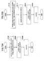
- FIG. 12, FIG. 13, FIG. 14, and FIG. 15 are flowcharts illustrating operations of the image processing device 200 according to the present embodiment.
- FIG. 12 is a flowchart illustrating operations of the image processing device 200 for reading the recording information 90 and carrying out specified processes according to the present embodiment.
- step S1000 the image reading unit 210 reads an image carrying the input recording information 90.
- step S2000 the image information acquisition unit 220 acquires the image information 91 corresponding to the image obtained by the image reading unit 210.
- step S3000 the image additional information acquisition unit 230 extracts the image additional information 92 from the image read by the image reading unit 210.
- the image additional information 92 includes letters or symbols, a bar code, a QR code, a dot pattern, or other visible marks added in the input recording information 90, these visible marks can be removed from the image additional information 92.
- step S4000 the process determination unit 290, based on the image additional information 92, selects and determines the process to be executed in the multiple process execution unit 250.
- step S5000 the multiple process execution unit 250 performs processing based on output of the process determination unit 290 and the image additional information 92.
- FIG. 13A and FIG. 13B are flowcharts illustrating operations of the transmission information generation unit 260 for generating a document to be transmitted based on the image additional information 92.
- FIG. 13A is a flowchart illustrating operations of the image processing device 200 when the transmission information is included in the image additional information 92
- FIG. 13B is a flowchart illustrating operations of the image processing device 200 when the address for storing the transmission information is included in the image additional information 92.
- step S5100 the image transmission information extraction part 261 extracts the transmission information from the image additional information 92.
- step S5200 from the extracted transmission information and the image information 91, the transmission document generation part 264 creates a document corresponding to the transmission device specified in the image additional information 92, such as a facsimile machine or a mailer.
- the transmission device may be specified from an input device (not illustrated).
- step S5300 the document created by the transmission document generation part 264 is transmitted to a target transmission address specified in the transmission information via the facsimile I/F 49 or the network I/F 59.
- step S5110 from the image additional information 92, the address acquisition part 262 extracts a transmission information address, which indicates the position for storing the transmission information.
- step S5111 the image transmission information acquisition part 263 accesses the transmission information address given by the address acquisition part 262 to obtain the transmission information including the transmission information address.
- step S5210 from the transmission information obtained in step S5211 and the image information 91, the transmission document generation part 264 creates a document corresponding to the transmission device, which is specified in the image additional information 92 or the transmission information.
- the transmission device may be specified from an input device (not illustrated).
- step S5310 the document created by the transmission document generation part 264 is transmitted to a target transmission address specified in the transmission information via the facsimile I/F 49 or the network I/F 59.
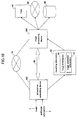
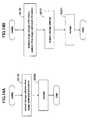
- FIG. 14A and FIG. 14B are flowcharts illustrating operations of the storage information generation unit 270 for storing the image information 91 at a given position based on the image additional information 92.
- FIG. 14A is a flowchart illustrating operations of the storage information generation unit 270 when the storage information is included in the image additional information 92
- FIG. 14B is a flowchart illustrating operations of the storage information generation unit 270 when the address for storing the storage information is included in the image additional information 92.
- step S5120 the image storage information extraction part 271 extracts the storage information from the image additional information 92.
- step S5320 based on the storage information extracted in step S5120, the image information 91 is stored at a given position in the storage device 60 connected to the image processing device 200 via the storage device I/F 69. Note that instead of the storage device 60, the image information 91 may be stored at a given position in a not-illustrated storage device existing on the network 50 connected to the image processing device 200 via the network I/F 59.
- step S5130 from the image additional information 92, the address acquisition part 272 extracts a storage information address, which indicates the position for storing the storage information.
- step S5131 the image storage information acquisition part 273 accesses the transmission information address obtained in step 5130 to obtain the storage information.
- step S5321 based on the storage information extracted in step S5131, the image information 91 is stored at a given position in the storage device 60 connected to the image processing device 200 via the storage device I/F 69. Note that instead of the storage device 60, the image information 91 may also be stored at a given position in a not-illustrated storage device existing on the network 50 connected to the image processing device 200 via the network I/F 59.
- FIG. 15A and FIG. 15B are flowcharts illustrating operations of the additional information acquisition unit 280 for acquiring the additional information based on the image additional information 92.
- FIG. 15A is a flowchart illustrating operations of the additional information acquisition unit 280 when the additional information is included in the image additional information 92
- FIG. 15B is a flowchart illustrating operations of the additional information acquisition unit 280 when the address for storing the additional information is included in the image additional information 92.
- step S5140 the additional information extraction part 281 extracts the additional information from the image additional information 92.
- step S5340 the information adding part 284 adds the additional information obtained in step S5140 to the image information 91 to generate an image.
- step S5150 the additional information position acquisition part 282 extracts an additional information address, which indicates the position for storing the additional information.
- step S5151 the additional information acquisition part 283 accesses the additional information address obtained in step S5150 to obtain the additional information.
- step S5350 the information adding part 284 adds the additional information obtained in step S5151 to the image information 91 to generate an image.
- FIG. 16A through FIG. 16C are data tables illustrating examples of a data structure of the image additional information 92.
- FIG. 16A is a table illustrating an example in which the image additional information 92 includes a series of variables of a given byte-length.
- the first variable represents "instruction”
- the following variables represent information necessary when executing the instruction.
- FIG. 16B is a table illustrating that the "instruction" variable is expressed by a binary or ASCII variable.
- the "instruction" variable equals "1".
- FIG. 16C is a table illustrating the meaning of the variables following the variable "instruction”.
- the "instruction" variable equals "1"
- the corresponding facsimile number of the recipient is assigned to the "data 1" variable.
- FIG. 17 is a diagram illustrating the image additional information 92 described in a descriptive language.
- a character string 921 represents a mail address for transmitting an e-mail message.
- the specific operation to be performed by the image processing device 200 is explicitly stored in the image additional information 92; but the present invention is not limited to this.
- image transmission information can be generated for mail transmission with this character string as the target address of e-mail transmission.
- image storage information can be generated for storing the image information 91 with this character string as the address for storing the image information 91.
- FIG. 18 is a block diagram illustrating a computer for executing the image processing method of the present embodiment.
- a main processor 3 of the computer is connected to the facsimile machine 40, the network 50, and the storage device 60 through a facsimile I/F 49, a network I/F 59, and a storage device I/F 69, respectively.
- the main processor 3 of the computer executes the image processing method of the present embodiment, and includes a CPU 4, a ROM 5, and a RAM 6.
- the CPU 4 reads out and executes programs stored in the ROM 5, thereby realizing the image processing method of the present embodiment.
- the CPU 4 also controls the RAM 6 and other peripheral devices.
- ROM 5 is the recording medium in which the program of the present invention is stored.
- RAM 6 is a temporary memory used when CPU 4 executes programs.
- the recording medium of the present embodiment is not limited to a ROM, but can be a hard disk, a CD-ROM, a DVD, and any other recording medium that is readable by a computer.
Landscapes
- Engineering & Computer Science (AREA)
- Multimedia (AREA)
- Signal Processing (AREA)
- Computer Vision & Pattern Recognition (AREA)
- Computing Systems (AREA)
- General Engineering & Computer Science (AREA)
- Editing Of Facsimile Originals (AREA)
- Image Processing (AREA)
- Control Or Security For Electrophotography (AREA)
- Facsimiles In General (AREA)
Applications Claiming Priority (2)
| Application Number | Priority Date | Filing Date | Title |
|---|---|---|---|
| JP2005380492 | 2005-12-28 | ||
| JP2006348446A JP4903034B2 (ja) | 2005-12-28 | 2006-12-25 | 画像処理装置、画像処理方法及びコンピュータプログラム |
Publications (1)
| Publication Number | Publication Date |
|---|---|
| EP1804484A1 true EP1804484A1 (de) | 2007-07-04 |
Family
ID=37976597
Family Applications (1)
| Application Number | Title | Priority Date | Filing Date |
|---|---|---|---|
| EP06256612A Withdrawn EP1804484A1 (de) | 2005-12-28 | 2006-12-28 | Vorrichtung, Verfahren und System zur Bildverarbeitung und Informationsaufzeichnungsmedium |
Country Status (3)
| Country | Link |
|---|---|
| US (1) | US20070153303A1 (de) |
| EP (1) | EP1804484A1 (de) |
| JP (1) | JP4903034B2 (de) |
Families Citing this family (16)
| Publication number | Priority date | Publication date | Assignee | Title |
|---|---|---|---|---|
| JP4828448B2 (ja) * | 2007-02-16 | 2011-11-30 | 株式会社リコー | 画像処理装置、画像処理方法及び画像処理プログラム |
| JP2008225000A (ja) * | 2007-03-12 | 2008-09-25 | Ricoh Co Ltd | 画像処理装置、画像処理方法、プログラム及び記録媒体 |
| JP4870599B2 (ja) * | 2007-03-16 | 2012-02-08 | 株式会社リコー | 画像処理システム、画像処理装置、画像処理方法及び画像処理プログラム |
| JP2008236200A (ja) * | 2007-03-19 | 2008-10-02 | Ricoh Co Ltd | 画像処理装置、画像処理方法、およびプログラム |
| US8325970B2 (en) * | 2007-03-19 | 2012-12-04 | Ricoh Company, Limited | Apparatus, method, and computer product for image processing |
| EP1973330B1 (de) * | 2007-03-19 | 2013-08-28 | Ricoh Company, Ltd. | Bildverarbeitungsvorrichtung und Bildverarbeitungsverfahren |
| JP4983610B2 (ja) * | 2008-01-10 | 2012-07-25 | 村田機械株式会社 | 画像処理装置 |
| JP4748169B2 (ja) * | 2008-02-01 | 2011-08-17 | 村田機械株式会社 | 画像形成装置 |
| JP4973540B2 (ja) * | 2008-02-21 | 2012-07-11 | 富士ゼロックス株式会社 | 画像処理装置及び画像処理プログラム |
| JP4974963B2 (ja) * | 2008-05-14 | 2012-07-11 | キヤノン株式会社 | 画像形成装置及びドットパターン較正方法ならびにプログラム |
| JP2010134653A (ja) * | 2008-12-03 | 2010-06-17 | Ricoh Co Ltd | 配布物印刷方法、配布物印刷装置及び配布物印刷プログラム |
| JP5231507B2 (ja) * | 2010-10-21 | 2013-07-10 | Necアクセステクニカ株式会社 | 画像情報提供システムおよび画像情報提供方法 |
| US8763904B2 (en) * | 2011-04-27 | 2014-07-01 | Intellectual Ventures Fund 83 Llc | Visibly forming an image and optical code |
| US8511575B2 (en) * | 2011-04-27 | 2013-08-20 | Intellectual Ventures Fund 83 Llc | Digital image file including optical code |
| US8903120B1 (en) * | 2011-12-21 | 2014-12-02 | Symantec Corporation | System and method for providing an image having an embedded matrix code |
| US9552691B2 (en) * | 2013-05-20 | 2017-01-24 | Bally Gaming, Inc. | Automatically generated display code for wagering game machine configuration |
Citations (8)
| Publication number | Priority date | Publication date | Assignee | Title |
|---|---|---|---|---|
| JPH11119597A (ja) * | 1997-10-20 | 1999-04-30 | Ricoh Co Ltd | 複写装置及びファクシミリ装置 |
| EP1001605A2 (de) | 1998-11-13 | 2000-05-17 | Xerox Corporation | Dokumentverarbeitung |
| EP1107570A2 (de) | 1999-12-02 | 2001-06-13 | Lucent Technologies Inc. | Automatische Ubertragung einer eingebetteter Fax/E-mailadresse |
| US6577409B1 (en) | 1999-02-19 | 2003-06-10 | Hewlett-Packard Development Company, L.P. | Method and apparatus for controlling a scanning device |
| JP2004343564A (ja) * | 2003-05-16 | 2004-12-02 | Ricoh Co Ltd | ファクシミリ装置 |
| US20050071738A1 (en) * | 2003-09-30 | 2005-03-31 | Park David J. | Scan document identification-send scanning using a template so that users can handwrite the destination and identification information |
| JP2005085246A (ja) * | 2003-09-04 | 2005-03-31 | Masatoshi Ouchi | リンク情報印刷・読取、およびリンク先情報記録・参照方法と装置 |
| WO2005086469A1 (en) * | 2004-03-04 | 2005-09-15 | Visioneer, Inc. | Document routing method and software therefor |
Family Cites Families (8)
| Publication number | Priority date | Publication date | Assignee | Title |
|---|---|---|---|---|
| JPH0775393B2 (ja) * | 1990-08-23 | 1995-08-09 | 富士ゼロックス株式会社 | 編集機能付き複写機 |
| US5465167A (en) * | 1992-03-20 | 1995-11-07 | Xerox Corporation | Using an image from a form in automatic creation of a form or sheet |
| US5959290A (en) * | 1998-01-08 | 1999-09-28 | Xerox Corporation | Image input device and method for providing scanning artifact detection |
| JP3754849B2 (ja) * | 1998-10-30 | 2006-03-15 | キヤノン株式会社 | データ通信装置及び制御方法及び記憶媒体及び画像印刷システム |
| JP4100856B2 (ja) * | 2000-05-16 | 2008-06-11 | キヤノン株式会社 | 画像形成装置 |
| JP3596604B2 (ja) * | 2000-12-07 | 2004-12-02 | 日本電気株式会社 | 出力装置コントローラ |
| JP4566474B2 (ja) * | 2001-07-30 | 2010-10-20 | パナソニック株式会社 | 画像処理装置および画像処理方法 |
| JP2003266863A (ja) * | 2002-03-19 | 2003-09-25 | Casio Electronics Co Ltd | 印刷システム及び印刷装置 |
-
2006
- 2006-12-25 JP JP2006348446A patent/JP4903034B2/ja not_active Expired - Fee Related
- 2006-12-27 US US11/645,499 patent/US20070153303A1/en not_active Abandoned
- 2006-12-28 EP EP06256612A patent/EP1804484A1/de not_active Withdrawn
Patent Citations (8)
| Publication number | Priority date | Publication date | Assignee | Title |
|---|---|---|---|---|
| JPH11119597A (ja) * | 1997-10-20 | 1999-04-30 | Ricoh Co Ltd | 複写装置及びファクシミリ装置 |
| EP1001605A2 (de) | 1998-11-13 | 2000-05-17 | Xerox Corporation | Dokumentverarbeitung |
| US6577409B1 (en) | 1999-02-19 | 2003-06-10 | Hewlett-Packard Development Company, L.P. | Method and apparatus for controlling a scanning device |
| EP1107570A2 (de) | 1999-12-02 | 2001-06-13 | Lucent Technologies Inc. | Automatische Ubertragung einer eingebetteter Fax/E-mailadresse |
| JP2004343564A (ja) * | 2003-05-16 | 2004-12-02 | Ricoh Co Ltd | ファクシミリ装置 |
| JP2005085246A (ja) * | 2003-09-04 | 2005-03-31 | Masatoshi Ouchi | リンク情報印刷・読取、およびリンク先情報記録・参照方法と装置 |
| US20050071738A1 (en) * | 2003-09-30 | 2005-03-31 | Park David J. | Scan document identification-send scanning using a template so that users can handwrite the destination and identification information |
| WO2005086469A1 (en) * | 2004-03-04 | 2005-09-15 | Visioneer, Inc. | Document routing method and software therefor |
Also Published As
| Publication number | Publication date |
|---|---|
| JP4903034B2 (ja) | 2012-03-21 |
| JP2007202132A (ja) | 2007-08-09 |
| US20070153303A1 (en) | 2007-07-05 |
Similar Documents
| Publication | Publication Date | Title |
|---|---|---|
| US8590775B2 (en) | Image processing apparatus, image processing method, and computer readable storage medium | |
| US7860266B2 (en) | Image processing system and image processing method | |
| EP2264995B1 (de) | Bildverarbeitungsvorrichtung, Bildverarbeitungsverfahren und Computerprogramm | |
| US8203748B2 (en) | Image processing apparatus, control method therefor, and program | |
| EP1804484A1 (de) | Vorrichtung, Verfahren und System zur Bildverarbeitung und Informationsaufzeichnungsmedium | |
| JP5195519B2 (ja) | 文書管理装置、文書処理システム、文書管理方法 | |
| JP5511450B2 (ja) | 画像処理装置、画像処理方法及びプログラム | |
| US20070279672A1 (en) | Image processing apparatus and image processing method | |
| US20090037463A1 (en) | Image processing apparatus, control method thereof, and storage medium that stores program thereof | |
| JP2009165088A (ja) | 画像処理装置 | |
| JP2011119871A (ja) | 画像管理装置、および画像管理方法 | |
| JP4933415B2 (ja) | 画像処理装置、方法、並びにプログラム | |
| EP1973324A1 (de) | Vorrichtung, Verfahren und Computerprogramm zur Bildverarbeitung | |
| CN101277358B (zh) | 用于图像处理的装置和方法 | |
| JP6397183B2 (ja) | 画像処理装置及び方法とプログラム | |
| JP4673200B2 (ja) | 印刷処理システムおよび印刷処理方法 | |
| JP2008229912A (ja) | 画像形成装置、及び画像形成方法 | |
| JP2012039236A (ja) | 画像処理装置、画像処理方法、及び、画像処理プログラム | |
| KR100601676B1 (ko) | 편집기능을 갖는 문서 스캔 방법 및 장치 및 그를 이용한복합기 | |
| JP2007148486A (ja) | 文書閲覧支援方法および文書閲覧支援システム並びに文書処理装置およびプログラム | |
| JP2008193234A (ja) | 画像処理装置、画像処理装置の制御方法、および画像処理装置の制御プログラム | |
| JP3899852B2 (ja) | 画像読取装置、画像処理方法、画像処理プログラム、およびコンピュータ読み取り可能な記録媒体 | |
| JP5979950B2 (ja) | 画像処理装置及びその制御方法、並びにプログラム | |
| JP2010109653A (ja) | 画像読取装置、画像形成装置、画像読取方法および画像読取プログラム | |
| JP6279025B2 (ja) | 画像処理装置、画像処理装置の制御方法、及びプログラム |
Legal Events
| Date | Code | Title | Description |
|---|---|---|---|
| PUAI | Public reference made under article 153(3) epc to a published international application that has entered the european phase |
Free format text: ORIGINAL CODE: 0009012 |
|
| 17P | Request for examination filed |
Effective date: 20070120 |
|
| AK | Designated contracting states |
Kind code of ref document: A1 Designated state(s): AT BE BG CH CY CZ DE DK EE ES FI FR GB GR HU IE IS IT LI LT LU LV MC NL PL PT RO SE SI SK TR |
|
| AX | Request for extension of the european patent |
Extension state: AL BA HR MK YU |
|
| AKX | Designation fees paid |
Designated state(s): DE ES FR GB IT NL |
|
| 17Q | First examination report despatched |
Effective date: 20101006 |
|
| STAA | Information on the status of an ep patent application or granted ep patent |
Free format text: STATUS: THE APPLICATION IS DEEMED TO BE WITHDRAWN |
|
| 18D | Application deemed to be withdrawn |
Effective date: 20150701 |